From Colonizing the Moon in Britannica Yearbook of Science and the Future (1972)
Halfway to Anywhere
Lifting your rocket from Terra's surface into circular orbit takes an unreasonably large amount of delta V. As a matter of fact, if your missions use Hohmann trajectories, the lift-off portion will take about the same delta V as does the Hohmann from Terra to the destination planet. As Heinlein put it:
Mr. Heinlein and I were discussing the perils of template stories: interconnected stories that together present a future history. As readers may have suspected, many future histories begin with stories that weren't necessarily intended to fit together when they were written. Robert Heinlein's box came with "The Man Who Sold the Moon." He wanted the first flight to the Moon to use a direct Earth-to-Moon craft, not one assembled in orbit; but the story had to follow "Blowups Happen" in the future history.
Unfortunately, in "Blowups Happen" a capability for orbiting large payloads had been developed. "Aha," I said. "I see your problem. If you can get a ship into orbit, you're halfway to the Moon."
"No," Bob said. "If you can get your ship into orbit, you're halfway to anywhere."
How much delta V does it take to go from Low Terra Orbit to Mars orbit? About 5.6 kilometers per second.
How much delta V does it take to go from the surface of Terra to Low Terra Orbit? 7.6 Freaking kilometers per second, that's what! In other words it takes more delta V to travel the pathetic 360 kilometers up to Low Terra Orbit as it does to travel the 228,000,000 kilometers to Mars!
From Low Terra Orbit, where can you travel to with 7.6 km/s? Oh, only to the Planet Saturn, 1,433,000,000 kilometers towards the edge of the entire solar system.
Rob Davidoff suggests that in a rocketpunk future, people will no longer use the expression "worth its weight in gold." Instead they will say "worth its weight in upmass", referring to the outrageous cost of shipping any payload from Terra's surface into Low Terra Orbit.
But the delta V cost breakdown is interesting. Getting into orbit takes just a little bit of delta V. It is making sure you stay in space that takes a freaking lot of delta V.
A little sounding rocket can easily rise from 50 to 1,500 kilometers above Terra's surface, where outer space starts about 150 kilometers up. Then the propellant runs out, and the poor little rocket finds itself unsupported hundreds of kilometers up. So it plummets to its doom.
How do you support the sad little rocket? If it uses propellant it will eventually run out, sooner more than later. You can't build rocket legs that are hundreds of kilometers long. You can't use a helicopter blade because there is no air.
But what you can do is put the rocket in an "orbit". An orbit is a clever way to constantly fall but never hit the ground. The trouble is that entering an orbit takes a freaking lot of delta V, about 8 kilometers per second around Terra.
Of course, once you have torchships you can stop all this child's play with wimpy Hohmann transfers and start doing some big muscular Brachistochrone trajectories. Brachistochrones typically require delta Vs that are hundreds of times more than the equivalent Hohmann. So any ship that can handle a Brachistochrone is not going to even notice the delta V cost for lift-off.
But even with torchships, the real bottle-neck restricting developing space resources remains the cost to boost payloads into Earth orbit.
The traveling-public gripes at the lack of direct Earth-to-Moon service, but it takes three types of rocket ships and two space-station changes to make a fiddling quarter-million-mile jump for a good reason: Money.
The Commerce Commission has set the charges for the present three-stage lift from here to the Moon at thirty dollars a pound. Would direct service be cheaper? A ship designed to blast off from Earth, make an airless landing on the Moon, return and make an atmosphere landing, would be so cluttered up with heavy special equipment used only once in the trip that it could not show a profit at a thousand dollars a pound! Imagine combining a ferry boat, a subway train, and an express elevator. So Trans-Lunar uses rockets braced for catapulting, and winged for landing on return to Earth to make the terrific lift from Earth to our satellite station Supra-New York. The long middle lap, from there to where Space Terminal circles the Moon, calls for comfort-but no landing gear. The Flying Dutchman and the Philip Nolan never land; they were even assembled in space, and they resemble winged rockets like the Skysprite and the Firefly as little as a Pullman train resembles a parachute.
The Moonbat and the Gremlin are good only for the jump from
Space Terminal down to Luna . . . no wings, cocoon-like acceleration-and-crash hammocks, fractional controls on their enormous jets.
From SPACE JOCKEY by Robert Heinlein (1949)
FUNDAMENTAL COST OF PUTTING STUFF IN ORBIT
What is the minimum energy of orbit, and how does that compare to the energy in a chemical rocket’s propellant?
Accessing a 150km LEO orbit requires first the energy to get to 150km. That’s roughly (in Energy/mass, or J/kg, aka m^2/s^2, the unit I’ll mostly use here): 150km*9.8m/s^2.
Orbital velocity at 150 km altitude is just v=sqrt(mu/a), where the distance from the center of the Earth a = r_Earth + 150km. Mu is the “standard gravitational parameter” of Earth, or ~3.986*10^14 m^3/s^2.
(BTW, I’ll write numbers like 3.986*10^14 in a more compact notation: 3.986E14.)
But we can minus the speed from the rotation of the Earth: v= sqrt(3.986E14m^3/s^2/(r_Earth+150km)) – 2*pi*r_Earth/day
Now we need to make this in terms of energy in order to add that potential energy from being 150km high:
E_specific (energy/mass) = .5*(sqrt(3.986E14m^3/s^2/(r_Earth+150km)) – 2*pi*r_Earth/day) + 150km*9.8m/s^2
Which is roughly: 28,480,000 m^2/s^2 or 28.5MJ/kg. That’s 7.9kWh/kg or just under $1 per kg to LEO at typical 10-12 cents per kWh.
And in terms of delta-v, it’s: v = sqrt(2*E) = 7550m/s or so.
That’s zero aero or gravity drag, launching due East on the equator. Imagine a 150km tall tower with a 100% efficient electromagnetic launch mechanism on the top, including the energy required to lift stuff up that tower and assuming no energy loss from the sled, no mass for the encapsulating of the payload, and 100% efficiency for electromagnetic launch. None of these are realistic assumptions.
Let’s compare with chemical launch. Assume a hypothetical stoichiometric methane/oxygen rocket engine operating at 3.7km/s exhaust velocity. This is very aggressive (especially at sea level), would probably melt the engine due to operating stoichiometrically, but it may actually be possible.
A stoich methane/oxygen mix, with methane having 55.5MJ/kg specific energy and the mix having 11.1MJ/kg, would have a theoretical exhaust velocity, if you totally convert chemical energy to jet energy, of 4.712km/s, so 3.7km/s isn’t physically impossible in the least (would be feasible in vacuum, but would require incredibly high pressures at sea level).
Anyway, let’s assume a mass ratio of, say, 25 for each stage. Let’s assume a 100 ton payload. The first stage weighs 120 tons dry (25 times that wet), and the next stage 10 tons dry (etc). That gets us 9km/s delta-v, which we’ll say is good enough, launching on the equator due East to 150km altitude.
We assume the dry mass magically can be recovered at no mass penalty (I will address this in another post…).
Mass of the propellant is: 120*24 + 10*24 = 3120 tons. Or 31.2 kg of propellant per kg to orbit. At 11.1MJ/kg, that’s 346MJ/kg of chemical energy in the form of methane. Natural gas is about $0.30 per therm in bulk. A therm is about 105MJ. So the cost of chemical energy to put stuff in orbit via chemical rocket like I described is actually ALSO $1/kg, and with arguably more realistic (though also aggressive) assumptions.
Moral of the story: It’s not, and never ever has been, about the cost of energy to get to orbit. Such arguments are flawed.
In the movie Interstellar, our hero Cooper is stuck on Terra. Which is a planet with 100% Earth Gravity, by definition.
NASA transports Cooper up to a starship using a monstrously huge rocket.
But in a breath-taking breach of self-consistency, Cooper later lifts off of a planet with 130% Earth Gravity with an itty-bitty teeny-tiny space ship. So why didn't NASA use a similar ship to get Cooper up to the starship in the first place?
Polar orbits pass over both the north and south poles, with an inclination close to 90 degrees with respect to the equator. But the important point is a satellite in polar orbit will eventually pass over every single spot on Terra. Heinlein calls these "ball of yarn" orbits, since the path of the satellite resembles wrapping a strand of yarn around a yarn ball. This is why such orbits are used for Earth-mapping, Earth-observation, some weather satellites … and reconnaissance satellites aka "spy" satellites.
For communication satellites, space stations, resupply missions, space exploration, and pretty much everything else, you launch into equatorial orbits.
LAUNCH CORRIDOR
When deciding where to put a launch site, you have to plan around the Launch Corridor. This is the path the rocket will take when launching which will [1] allow the rocket to reach the desired orbit and [2] if the rocket engines fail, the rocket (or the remaining flaming rocket debris) will only fall on uninhabited areas as long as it stays inside the launch corridor. The standard practice is to arrange launch corridors to be over the ocean. Failing that, you need land areas where a rain of flaming rocket bits is unlikely to result in lawsuits or negative publicity. And of course ones that do not violate another nation's sovereign airspace.
During launch, the range safety officer will be watching the rocket like a hawk. If the rocket shows signs of failing to reach orbit, the officer will make a note to dispatch a rescue/cleanup team. If the rocket shows signs of leaving the launch corridor, the officer will hit the panic buttons. Unmanned rockets will shutdown their engines and vent their propellant. Manned rockets will have the on-board pilot take action, but if they are ineffective the range safety officer might have to shoot the rocket out of the sky.
Obviously polar launch corridors have to be along the north-south axis.
The United States uses Vandenberg AFB Space Launch Complex 6 (SLC-6 aka "Slick Six") to launch into polar orbits. Rockets launch due south so the launch corridor is thousands of miles of uninhabited Pacific ocean. The alternative is to launch due north, but that puts the launch corridor right across California, the long way.
EQUATOR BOOST
Equitorial launches have a second consideration besides the launch corridor.
When you are dealing with feeble launch vehicles using chemical propulsion you need to use every trick you can find. They have grotesque mass ratios which really cut into the payload mass. The most important trick is one to reduce the delta V the rocket needs to achieve orbit.
Since Terra is spinning on its axis, when the rocket is sitting on the ground it is actually already moving. At least it is moving relative to the desired orbit, which is the important thing. If you are standing in New York City; you, the ground, the skyscrapers, the taxi cabs, and everything else is moving at 356 meters per second. The only reason everything seems stationary is because everything is moving together. Now remember that on Terra everything is moving due east because that is the direction Terra is spinning on its axis.
The technical term is the tangential velocity of Terra's surface. It is equal to
tangentialVelocity = tangential velocity at planet surface (m/s) (Terra = 465 m/s) π = pi = 3.14159… planetRadius = radius of the planet (meters) (Terra = 6,371,000) siderialRotation = siderial rotation period (seconds) (Terra = 86,164 seconds, which is actually 23 hours, 56 minutes, 4 seconds) cos(x) = cosine of x (do not make the mistake of giving your spreadsheet or calculator "x" in degrees when it is expecting radians or something)
Example
What is the tangential velocity at planet surface for New York, Terra?
I gave you the entire equation in case you wanted to do the calculations for an extraterrestrial planet. If you are just trying to place launch sites on Terra, the equation is:
tangentialVelocity = 465 * cos(latitude)
The point is that the delta V the launch vehicle needs to achieve orbit is reduced by the tangential velocity of the launch site. Bottom line is the closer you can put the launch site to the equator, the better.
For Terra, the pure orbit delta V is about 9,700 m/s (would be 7,800 m/s except for air-drag, gravity-drag, and vertical acceleration). But when launching from New York the delta V is only 9,700 - 356 = 9,344 m/s. And launching from the equator it is 9,700 - 465 = 9,235 m/s. That kind of delta V reduction can buy you lots of extra payload.
Keep in mind that since Terra is spinning due east, the rocket has to launch in an easterly direction in order to take advantage of the bonus. By the same token, if the stupid rocket launches west, the bonus turns into a liability. Launching westward on Terra's equator means the rocket needs an additional 465 m/s to reach orbit.
The important point is that on Terra the equatorial launch corridor is going to point due east.
The better science fiction novels put Terran equatorial launch sites as close to the equator as possible, and where an eastward launch corridor passes over lots of ocean (i.e., on the east coast, near the equator).
The North Maluku province of Indonesia has parts right on the equator. It has pretty much the entire Pacific Ocean to use as a launch corridor, except only scattered tiny islands in the launch corridor. Possible launch site.
There is a part of the coast of Brazil that is right on the equator. It has pretty much the entire Atlantic Ocean to use as a launch corridor. Possible launch site.
Parts of the Galápagos Islands are right on the equator. Unfortunately it only has 906 km of Pacific Ocean launch corridor before flaming rocket bits start raining down on Ecuador. Possible launch site.
In ARTEMIS by Andy Weir the launch site is in Kenya, with parts right on the equator. It has pretty much the entire Indian Ocean to use as a launch corridor. However, the part closest to the equator that does not include Somalia in the launch corridor is located at 1.7° S latitude.
In ISLANDS IN SPACE by Arthur C. Clarke the launch site is at New Guinea, with point closest to equator at about 2.6° S latitude. It has pretty much the entire Pacific Ocean to use as a launch corridor, except for the Solomon Islands.
The real world Guiana Space Centre in French Guiana is at about 5° N latitude. It has pretty much the entire Atlantic Ocean to use as a launch corridor.
Palmyra Atoll is at about 5° N latitude. It has pretty much the entire Pacific Ocean to use as a launch corridor. And it is a US unorganized incorporated territory. Drawbacks include it is pretty much on the opposite side of Terra from the continental US so that logistics is a nightmare, and the highest point is (currently) only 10 meters above sea level.
The US Virgin Islands are at about 17.7° N latitude. It has pretty much the entire Atlantic Ocean to use as a launch corridor. Possible launch site.
In High Justice by Jerry Pournelle the launch site is at Cabo San Lucas, Mexico. It is at an unhelpful 22.8° N latitude. And it only has 390 kilometers of launch corridor.
The real world Kennedy Space Center Launch Complex 39 is at an ugly 28.5° N latitude. But the United States does not get that much closer to the equator. It has pretty much the entire Atlantic Ocean to use as a launch corridor.
The real world Baikonur Cosmodrome is at an almost utterly worthless 45.6° N latitude. What's worse it it has to launch at a 51.6° inclination, since China takes a very dim view of being in the launch corridor. Sadly Baikonur is probably located at the best out of Russia's poor selection of launch sites.
REJECTED LAUNCH SITES
(ed note: Once again, rocket expert Michel Van points out some mistakes I've made. )
After reading Surface to Orbit Boost/Launch Sites, I have some remarks on them and why they not taken
This site was used by British for their Military Rocket include Blue Streak => Europa 1 rocket. But the site has issues. One: you can only launch into Polar orbit (like Cabo San Lucas), otherwise the rocket stages fall on metropolitan areas on east coast. Two: transporting the rocket from manufactures (Britain, France and Germany) to Woomera was expensive.
Because of political issues, the shipment went over South Africa instead through the Suez cannel (blocked temporarily due to wars). This was one of reason why Black Arrow was cancelled (high shipment cost)
The site lies outmost north of continent, ideal to launch to Equator
But there is no infrastructure what so ever, needed to support a Launch complex. Such as a deep water harbor. There is also an issue with frequent cyclones.
It was proposed to dismantle the Blue Streak launch complex in Woomera and rebuild in Darwin, but ELDO had a better idea.
Roscosmo and private investor look into the option to launch from Darwin but again there was nothing there except high investment costs.
In end Roscosmo signed a very good deal with ESA (see below)
All three islands were proposed as launch sites.
But operations at those sites would be a nightmare, due to distance to rocket manufacture and lack of logistic at site.
In addition, Johnson Atoll is subject to frequent cyclones and occasional nuclear fallout from near by nuclear testing.
The good point for the New Guinea site is it is very close to the equator.
The bad points are it is also very distant from the rocket manufactures and there is no infrastruction. In addition, the launch site has to be build right in the middle of a jungle.
15 proposed replacement sites were examined, but only one made the cut.
ROUSSILLON (south France) REJECTED: too north of the equator, launch corridor only along the Mediterranean sea
SEYCHELLESREJECTED: unable to build an aircraft landing strip of 3000 meter length.
TRINIDADREJECTED: Polar launch not possible. Also the nation was politically unstable in 1960.
TUAMOTUS ATOLLREJECTED: 20,000km from France, no infrastructure, no water, frequent cyclones and difficult to defend
NUKU-HIVA ATOLLREJECTED: unable to build landing strip of 3000 meter length.
LA DÉSIRADEREJECTED: Too small, no infrastructure and frequent cyclones
MARIE-GALANTEREJECTED: Polar launch not possible, too small, no infrastructure and frequent cyclones
DJIBOUTI REJECTED: too political unstable, no way to defend site. Today it is a hellhole of civil war. Turkey wants to install a launch pad for their home made launcher.
MOGADISHUREJECTED: too politically unstable, no way to defend site
Today it is an even darker hellhole than Djibouti and yes the Turks are also looking there for a launch site.
DARWINREJECTED: no infrastructure and frequent cyclones
SRI LANKAREJECTED: too political unstable, no way to defend the site
TÔLANAROREJECTED: too far south of the equator, no infrastructure
NOUADHIBOUREJECTED: too politically unstable, no way to defend site
BELÉMREJECTED: too politically unstable, no way to defend site
confirmed by military putsch that follow
CAYENNEREJECTED:Was the Best site for CNES and Military but missing a harbor and infrastructure.
CNES director General Aubinière made inspection of Guiana in 1963 and found perfect site in Guiana: KOUROUACCEPTED
Ideal with deep water harbor, airport and infrastructure; plus a French legion camp in place.
It is very near equator and can also perform polar launches.
So in march 1964 president General De Gaule visit Guiana and announce the construction of the Launch Center
ELDO (today ESA) was also looking for a Europa 2 launch site in 1968.
After looking at similar list (including Kenya) they decided to use the existing Guiana Space Center.
The French had already built an operational Center there with all infrastructure the ESA needed.
That is the reason why the Russians build a Soyuz launch pad at Guiana, all you need is already there. (And for moment, this is the only launch site for ROSCOSMO to reach the Chinese Space Station in orbit !).
Other proposals
in 1960 Britain realised that Blue Streak will never be an IRBM
and proposed rockets as base of Launcher for space Program under Commonwealth of Nation.
The members reaction was lukewarm (except Australia and Canada).
One idea was to build launch site on Mt. Kenya !
With an altitude of 5199 meters high you mostly above the dense atmosphere,
and could use better vacuum adapt rocket engine.
same even better for Equator with 6272 meter high Chimborazo.
Today both sites are considered for Space Elevators anchors
From by ()
New Guinea
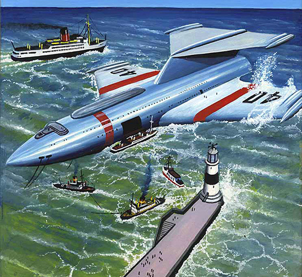
artwork by Alex Schomburg
The New Guinea mountains, just south of the Equator and rising in places more than three miles above sea level, must once have been about the wildest and most inaccessible spots on Earth. Although the helicopter had made them as easy to reach as anywhere else, it was not until the twenty-first century that they became important as the world's main springboard to space.
There are three good reasons for this. First of all, the fact that they are so near the Equator means that, because of the Earth's spin, they're moving from west to east at a thousand miles an hour. That's quite a useful start for a ship on its way out to space. Their height means that all the denser layers of the atmosphere are below them, so that air resistance is reduced and the rockets can work more efficiently. And — perhaps most important of all — there's ten thousand miles of open Pacific stretching away from them to the east (so if a rocket crashes there is no danger of it obliterating a town). You can't launch spaceships from inhabited areas: apart from the danger if anything goes wrong, the unbelievable noise of an ascending ship would deafen everyone for miles around.
Port Goddard is on a great plateau, levelled by atomic blasting, almost two and a half miles up. There is no way to reach it by land — everything comes in by air. It is the meeting place for ships of the atmosphere and ships of space.
When I first saw it from our approaching jet, it looked a tiny white rectangle among the mountains. Great valleys packed with tropical forests stretched as far as one could see. In some of those valleys, I was told, there are still savage tribes that no one has ever contacted. I wonder what they think of the monsters that fly above their heads and fill the sky with their roaring… (they are probably all deaf by now, I guess New Guinea is not classified as an "inhabited area")
Now one would have expected that the International Space Station (ISS) would be in a 28.5° inclined orbit, which is the orbit you get when launching due East of Kennedy Space Center (latitude 28.5° N).
But it isn't, the ISS is instead in a 51.6° inclined orbit. Why? So that Russian cargo rockets from Baikonur Cosmodrome can reach it. Launching into a different inclination than the space port's latitude costs rocket propellant and reduces payload.
Changing the ISS planned inclination to 51.6° was in retrospect a very good decision. When NASA stupidly cancelled the Space Shuttle program before the replacement vehicle was online, they assured everybody that the replacement would be flying by 2014 at the latest. This would make a small three-year gap in NASA's ISS transport ability. Unfortunately and predictably when 2014 arrived NASA has not even started work on deciding which of the many proposals will be used, much less bending metal and cranking out functional rockets. This leaves NASA at the mercy of the Russians for access to the ISS, but without the Russians there would be no access at all and the station would have long ago burnt up in reentry like Skylab. But I digress.
Clever readers will say but wait! Baikonur Cosmodrome is at latitude 45.6°, should not that be the inclination?. In a perfect world, yes, but there is a problem. When a spacecraft is launched from Kennedy Space Center the lower stages fall into the Atlantic Ocean. And if something goes really wrong, the entire spacecraft can abort and ditch into the ocean as well. If Baikonur Cosmodrome did the same thing, large spent lower stage boosters and/or huge flaming aborting Russian spacecraft would crash into Mainland China, and the political situation would rapidly deteriorate. To avoid that unhappy state of affairs, Russian spacecraft launched from Baikonur go at a 51.6° inclination, so falling rocket bits will miss China.
The Russians already have an annoying problem with the lack of warm-water ports for seagoing vessels. They really dislike having much the same problem with respect to space launches. Therefore they are in negotiations for launch privileges at the ESA'sGuiana Space Centre, which is optimally located quite near the Equator and to the West of the Atlantic Ocean.
BRAZIL SPACEPORT
At 5.16 degrees north latitude, Kourou in French Guiana is about as close as you can get to lying directly on the Earth's equator — an almost ideal spot from which to launch a spaceship.
Emphasis on "almost."
To hear Brazil tell it, you see, there's actually an even better place to put a spaceport than Kourou: Namely, the Brazilian city of Alcantara. Located in the state of Maranhao, at 2.40 degrees south latitude, Alcantara is less than half as far away from the equator as Kourou, and Brazil would really like to convince space companies that this makes Alcantara more than twice as attractive a place from which to launch their rockets. (Additionally, like Kourou, Alcantara is conveniently located next to a large body of water to the east, into which falling rocket parts can safely splash down).
Last year, Brazil made much this same argument to a group of representatives from U.S. space launch companies. Ranging from large to small in size, with names including Boeing and Lockheed Martin and even tiny rocket launcher Vector, American space launch companies made the trek to Brazil.
In an article last week describing Brazil's pitch to the space establishment, Reuters reports that Brazil is offering Alcantara as a budget-priced alternative to launching from Kourou (a favorite launch site of Airbus subsidiary Arianespace). According to the Brazilians, launching from Alcantara can save North American space launch companies as much as "one third" on their fuel costs. This is because such launches get a bigger speed boost from the Earth's rotation, which is fastest at the equator and slows progressively as one moves north or south from it.
Still, it's not entirely clear what launch site Brazil picked as its "control" when making cost comparisons — perhaps the Kodiak Launch Complex in Alaska, from which Vector, for example, plans to make its first orbital launch later this year. In contrast, relative to launches from better-known, more active spaceports such as Cape Canaveral, Vector CEO Jim Cantrell estimates that launching from Alcantara could yield fuel savings closer to 10% to 15%.
Location, location, location
Will 33% savings — or 15%, or 10% — be enough to convince space companies to shift their business south from Florida to Brazil? Maybe not, if that were the only advantage. But as Cantrell told me in a phone conversation over the weekend, there are other advantages to launching close to the equator on top of simple fuel savings.
Because of quirks in the ballistics of missile launch, Cantrell explains, there are certain orbits that simply cannot be achieved with ease when launching from high latitudes but can be easily achieved when launching from near the equator. Over the course of the next five years, the U.S.-based Space Enterprise Council estimates we could see as many as 600 small rocket launches take place. The more satellites go up, the more satellites can be expected to slot into orbits easier-reached from equatorial launching points. This could help Alcantara capture as much as 25% of the market, says the Council.
Caveats and provisos
In order for U.S. space companies like Boeing, Lockheed, and Vector to take advantage of Alcantara's offerings, however, a couple of obstacles must be overcome. First and foremost, a technology safeguards agreement (TSA) must be signed, whereby the United States State Department certifies Brazil's ability to protect U.S. "launching and operating technologies."
Brazil is hoping to finalize such an agreement this year, permitting development of an Alcantara spaceport to move forward, and chances of that look good. After all, the U.S. already approved such a TSA once before, in 2000 — but Brazil's own Senate refused to ratify it. Presumably, if the political will is now present in Brazil to move forward, inking a new deal shouldn't be difficult.
Another issue is cost — not the cost of rocket fuel this time, but of diesel fuel. Alcantara is, after all, more than 3,200 miles distant from Cape Canaveral, which is a long lateral detour to ask companies to make just to lift their sats a few hundred miles above the Earth's surface! Brazil's distance would add significantly to shipping costs for any rockets (and satellites) that U.S. companies want to build in the U.S. and ship to Brazil for launch.
Granted, such factors don't prevent Airbus from using French Guiana as its preferred launch site, but it's still a factor to consider when gauging Brazil's chances of success. Cantrell estimates that shipping one of its small Vector-R rockets from the U.S. to Brazil might cost anywhere from $200,000 to $300,000 — a significant percentage of the company's estimated $1.5 million cost to put a small satellite in orbit.
Even if Alcantara turns out to be economically inadvisable for U.S. space launch companies, however, there's always the possibility that Brazil will try to use it as a springboard to launch its own space industry. As Reuters notes, Brazil is already working to develop a small rocket of its own, and intends to fly it out of Alcantara when ready — perhaps as early as next year.
If and when that happens, expect the market for space launch to become even more crowded.
(ed note: the ASPEN spacecraft being launched is a single-stage-to-orbit (SSTO) booster that uses turbojets and ramjets for the initial climb. The nuclear engines do not activate and become radioactive until an altitude of 30 kilometers is reached.)
Today, many would say the deepest
fear would be an SSTO crashing and
scattering radioactivity to the environment, a nuclear Challenger accident,
raising strident opposition by the public and other governments. Perhaps
this is the reason why nuclear SSTOs
have been ignored. But I see, instead,
the deepest concern to be premature
enthusiasm and strong competition by
foreign governments and their peoples
for them. This seems ironically absurd,
but it is not.
The SSTO’s most important need would be for launch and
emergency landing facilities as isolated as possible to mitigate harm to the
public from contingencies during take-offs and landings; yet they would need
long launch and landing corridors. The
use of launch and landing corridors
over the continental United States
would be unsuitable for early generation SSTOs; the Challenger accident
scattering debris over Texas and
Louisiana would remain a vivid
reminder. So new facilities would be
needed, but where? Islands in the
Pacific would get attention, as they are
quite isolated and if located in proximity to the equator allow the SSTO to
take advantage of the Earth’s rotation
to improve the payload fraction carried
to LEO. Their isolation, however,
would make them unattractive, as their
logistical costs would be high; but
most important, their political voices
would be weak.
Others would clamor
to host the launch and landing facility,
and would drown them out.
Of those voices, I think the loudest
would be from the governments of
Columbia, Ecuador, and Peru, in the
northwest portion of South America.
Each has isolated, sparsely populated
mountainous areas or plateaus several
miles high near the equator, yet logistically they are central in the Western
Hemisphere. Takeoffs from there
Would take advantage of the equatorial
boost, but the flight path itself could
occur over water or the Amazon jungle
basin with ramjet/turbojets, with the
nuclear engines firing as the SSTO
flies over the Atlantic Ocean. Then the
flight path would continue over the
sparsely inhabited countries of equatorial Africa, the dense jungles on the
Westem side and upland plateaus on
the east.
I suspect many countries
would vie to host an emergency-landing site and perhaps more than one
might be desirable. After Africa, the
flight path would be nearly all over the
Indian and Pacific Oceans, With emergency-landing sites on different islands
as appropriate. And the Wide Pacific
would allow a long glide path for the
return to base in Columbia, Ecuador,
or Peru. Essentially, this Would create a
launch and landing corridor Within a
band 10° north and south latitude of
the equator, most of which is over
sparsely inhabited regions or over
water.
WORLD MAP
The northwest part of South America has unique advantages for an SSTO spaceport. The sparsely
inhabited regions are about two miles high and close to the equator, both of which have advantages for
the launch. However, the area’s principal advantage lies in the launch and landing corridor that can be
created, about 10 degrees in latitude on either side of the equator. So the flight path to LEO would be
over sparsely populated areas or over water while the return from LEO would be over the wide Pacific
Ocean, whose many islands could serve as emergency landing strips.
click for larger image
From THE NUCLEAR ROCKET by James Dewar with Robert Bussard (2006)
Resuable Boosters
BEER-KEG ERA
Addressing a 1966 technical conference, NASA official
Harold Hornby said that today’s Saturn rockets and
other expendable space boosters represent a “beer-can
era” of launch vehicles. That is, the rockets are used
once and then thrown away.
Urging the development of reusable rockets, he
said the 1970s could highlight a “beer-stein” approach
that would permit some recovery and reuse of costly
space boosters and some additional capacity.
In the 1980s, said Hornby, space launch vehicles will
be entirely reusable and have vastly greater capabilities.
That, he said, will be rocketry’s “beer-keg era.”
(ed note: alas, the beer-stein era did not arrive in 1970, it had to wait until 1980 with the advent of NASA's space shuttle. Which was canceled, resulting in a hiatus until the arrival of SpaceX's Falcon 9)
From A FUNNY THING HAPPENED ON THE WAY TO THE MOON compiled by Bob Ward (1969)
18-wheelers, trains, cargo aircraft, and cargo ships would all be several orders of magnitude more expensive if the vehicles could only be used once then thrown away. You cannot amortize the cost much on a single trip. But that used to be industry standard in the space booster business. The rocket hauls the satellite into orbit, lets it go, then the rocket falls back to Terra and burns up in reentry.
NASA tried to create a reusable system with its Space Shuttle, but it miserably failed to meet its promised cost and utility goals, as well as design, cost, management, and safety issues. Blasted thing was actually more expensive than a throwaway rocket: $18,000 per kilogram delivered to LEO, while the expendable Proton could do it for $5,000 per kilogram.
So all the rocket companies laughed and laughed when Elon Musk founded SpaceX and announced he was developing a partially reusable booster rocket. The companies sat on their expansive derrières and patiently watched as SpaceX struggled through the lengthy development process, secure in the knowledge that Elon was going to fail.
Well, they ain't laughing now. Indeed the rocket companies are panicking. SpaceX reusable launch system is a going concern, the cost per kilogram of payload is way below any technology the other companies have, and now they are about 15 years worth of development time behind SpaceX. A SpaceX Falcon-9 can be refurbished for reuse for about 10% of the cost of building an entire new rocket. There is a penalty of a 30% reduction in payload mass when a Falcon-9 is flown in re-use mode. But according to SpaceX, they break even with the second flight of a Falcon-9, and save money from the third flight on. The customers even prefer to have their payloads boosted on re-used rockets, because the rockets have been flight tested so to speak.
Along the same lines as reusable boosters are the ground-based facilities that can fling things into orbit as long as the electricity keeps running. Economically they are equivalent to reusable boosters. They include such things as Lofstrom loops and laser launchers.
PARTIAL VS FULL REUSABILITY
This is a topic suggested by Doug Plata. What impact will partial reusability have on efforts to settle and exploit space?
Reusable Booster stages
SpaceX is working on a reusable booster stage. This has potentially enormous savings.
Why is reusing a booster such a big deal? Some might think getting above the atmosphere is a minor challenge compared to achieving orbital velocity. Lets take a look at hows and whys of vertical ascent.
The flight path angle is the angle between horizontal and the velocity vector.
If earth were an airless world, horizontal launches would be optimal. In other words the flight path angle would be zero.
But earth has an atmosphere. To avoid a long trip through the atmosphere a flight angle closer to vertical is called for.
Taking off from the earth at 8 km/s, a nearly vertical flight path angle vs horizontal take off.
Low earth orbit velocity is about 8 km/s. If a spacecraft achieved this velocity at earth's surface with a zero flight path angle, nearly a quarter of it's orbit (about 10,000 kilometers) would be through earth's atmosphere.
Most meteorites burn up in the mesosphere about 70 km up. Air density at this altitude is less than a thousandth of sea level. Orbital velocity at sea level would subject the rocket to extreme temperatures.
Dynamic pressure is another quantity to consider. Dynamic pressure is often denoted with the letter q. The maximum dynamic pressure a spacecraft endure is referred to as max-Q. The max-Q of the space shuttle was about 33 kilo-pascals. A severe hurricane has a dynamic pressure of 3 kilo-pascals.
8 km/s at sea level would give a dynamic pressure of about 40,000 kilo-pascals.
Before making the major horizontal burn to achieve orbital velocity, we must get above the dense lower atmosphere. The shortest path through the atmosphere is a vertical ascent.
But a vertical ascent incurs gravity loss.
Earth's surface gravity is 9.8 meters/sec^2. Each 102 seconds spent in vertical ascent costs 1 km/s delta V. Gravity loss is a major expense associated with ascent.
To minimize ascent time, a high thrust to weight ratio (T/W) ratio is desirable. The more oomph a booster stage has, the less time gravity loss is incurred.
A booster stage with more rocket engines will have a higher thrust to weight ratio. The Falcon 9 booster has 9 Merlin engines as compared to the second stage which has only 1.
Since a booster has 9 engines and the upper stage 1, would reuse mean 90% savings?
The upper stage also needs avionics, a power source, propellent tanks etc.. So I'd be surprised if the upper state is 10% of the expense. My guess would be more like 1/6. Still a 5/6 savings would be substantial.
But even a 5/6 savings wouldn't be realized by re-use. Still unknown are refurbishment costs. Also unknown is how many times a booster can be re-used.
I give better than even odds SpaceX's reusable booster will cut launch costs by 50%.
Reusable Upper Stage
After the booster stage has lifted the spacecraft above the atmosphere, the upper stage provides the horizontal burn to achieve orbital velocity. This take about 8 km/s.
Tsiolkovsky's rocket equation and an 8 km/s delta V budget mandate the upper stage is about 90% propellent and 10% dry mass. The smaller dry mass fraction means more tenuous structure and less thermal protection. It is hard to see how an upper stage could endure the extreme conditions of an 8 km/s re-entry into earth's atmosphere.
I would bet against SpaceX achieving a reusable upper stage (Mr. David won his bet. In 2018 Elon Musk announced that they were abanoning development for a Falcon-9 reusable upper stage. However that is still planned for the SpaceX Starship).
Reusable Capsule
A capsule doesn't need a huge delta V budget. Just enough to lower it's perigee so it passes through the upper atmosphere. With a delta V budget less than 1 km/s, a capsule can have robust structure as well as a substantial heat shield.
I give SpaceX better than even odds at achieving a reusable Dragon capsule.
What does re-use do to economies of scale?
An item can be much cheaper if many units are mass produced on an assembly line. With mass production, design and development is amortized to a marginal expense.
If the average rocket engine is re-used 10 times, we would need at least a ten fold market increase to maintain economies of scale.
Could re-use lower prices enough to boost the market ten fold or more? I am not sure this would happen. What's the market for launch vehicles? Communication sats, surveillance and weather sats, occasionally ferrying passengers to the I.S.S. It's not clear cutting launch costs by half or even two-thirds would explode this market.
Economies of Scale with Re-use
The are possible new markets such as space tourism or mining. I don't expect those markets to take off so as a launch costs millions.
But what if the entire package was re-usable? The upper stage as well as booster and capsule? Reducing the cost by another order of magnitude opens many new markets: orbital hotels, lunar and asteroid mining, bases on the moon and Mars, etc..
But for upper stage re-use we would need propellent sources other than from the bottom of earth's gravity well. We would need orbital infra-structure: ferries between the various orbits and regions in our earth moon neighborhood: LEO, GEO, EML1, EML2 and DRO.
Establishing this mining and transportation infra-structure could provide the initial market. Once infra-structure is established, development of space would proceed like a snow ball rolling down a hill.
In my opinion partial re-use isn't sufficient to get the ball rolling. But it's an important step toward achieving full re-use. What happens after full re-use? If we can cut expenses down to the point where propellent is the dominant cost, I'd expect the market to explode at an exponential rate.
Hiller’s concept for a giant helicopter that could ferry Saturn V first stages and catch them in midair.
Hiller Aircraft was a helicopter company based in Palo Alto, California, that thrived in the middle of last century, but was denied a U.S. Army helicopter contract as a result of shady—probably illegal—actions taken by Howard Hughes. Hughes’ OH-6A Cayuse—better known as “the Loach”—became the Army’s standard light scout helicopter of the Vietnam War, and although Hughes lost substantial money on the Army deal, the Loach’s descendants proved highly successful. Hiller’s proposal, the OH-5A, lost the Army contract and never succeeded as a commercial helicopter. Hiller was absorbed into Fairchild and eventually the company faded away. Today very few of its products remain flying, and its primary legacy is a small but history-packed museum off Route 101 in Palo Alto.
But back in 1965 the company made a proposal so bold that it bordered on insane: a giant helicopter with a rotor diameter bigger than the length of a football field, capable not only of transporting a Saturn V S-1C first stage, but of actually catching it in midair as it fell on a parachute. Strike that: it did not border on insane, it was insane. But those were heady days in the mid-1960s, a time when NASA was getting nearly five percent of the federal budget—many times more than today—and when the agency was doling out study contracts for everything from nuclear rockets to ion engines to 100-man space stations. The United States was kicking the Soviets’ asses in space. There was nothing America couldn’t do. According to Ken Spence, an aviation research and development engineer, Stan Hiller, who created and owned the company, had a wealth of creative passions and ideas. What Hiller really wanted was “a helicopter in every garage.” But why should a small helicopter company that had never gained a major contract, or built a helicopter capable of carrying more than six people, think small?
Of course, they never built their monster helicopter. They never even got money to study it. Their proposal, even if it had not been totally crazy, came at exactly the time that NASA’s budget was cresting its peak and about to head down, both because the agency had made its initial capital investments, like the launch pad facility at Cape Canaveral, and because Lyndon Johnson needed the money for other things and his budget chief recognized (correctly) that there was a lot of fat in the NASA budget. All that is left of Hiller’s proposal is a formerly working model in the company’s museum and the original unsolicited proposal submitted to NASA. Ken Spence built that model.
A model of Hiller’s “Rotary Wing System for Booster Recovery.”
Hiller did not call the idea a “helicopter,” at least not on the title page. Instead the company referred to it as a “Rotary Wing System for Booster Recovery.” In their proposal, Hiller noted that there were many concepts for Saturn first stage recovery, but that these all had drawbacks, including complexity, performance penalties, landing shock damage and/or seawater contamination. Hiller’s helicopter “would recover the booster in its own element”—i.e. in air. The helicopter could also be used as a crane or aerial transport for booster segments.
It would be gigantic. The rotor diameter would be over 120 meters (400 feet). Its empty weight would be over 200,000 kilograms (450,000 pounds), with a useful load of nearly 250,000 kilograms (550,000 pounds), for a gross weight of a whopping 453,000 kilograms (1,000,000 pounds).
According to the proposal, the helicopter would depart from the missile launching area or another suitable base with internal and external fuel tanks and head for the booster reentry area. The plan was for the helicopter to be capable of loitering in the recovery area for up to six hours, flying at an altitude of 4,500–6,000 meters (15,000–20,000 feet).
Upon sighting the booster, the helicopter would head for it and intercept it at approximately 3,000 meters (10,000 feet). The S-1C’s parachute system would be descending along a glide path with more forward than downward velocity. The helicopter would align with the glide path and approach from behind and above, descending to match trajectories with the booster. It would snag the pickup chute with a grappling hook suspended from the helicopter’s center of gravity and gradually assume the weight of the booster. The parachutes would be deflated and the booster suspended about 215 meters (700 feet) below the helicopter.
The concept of operations for catching a Saturn V first stage with a giant helicopter.
The helicopter would then reel in the booster, rotating it to a horizontal position and snugging it up underneath the helicopter—and then returning it to the launch area or some other destination on land. Of course, the S-1C stage would fall over 650 kilometers (350 nautical miles) from the launch site. How feasible was it for the world’s largest helicopter, carrying the world’s largest rocket, to fly this distance back home? What about wind? Although Hiller’s proposal did not say so, a far better solution would have been for the helicopter to set the stage down on a ship near the recovery area. Of course, it would have to be a big ship, like an aircraft carrier, or a barge. But nothing would be small with this concept.
The giant helicopter would utilize a concept that Hiller had worked on for years and tried unsuccessfully to sell to the Army: the rotor-tip-powered lifting system. For the large helicopter this involved putting a jet engine, or more likely two jet engines, on the tip of each of the three rotors—six jet engines in all, plus a seventh in the rear fuselage to power the tail rotor. The rotors would not have to turn very fast by helicopter standards, only about once per second. But even that would result in the advancing rotor tip approaching the speed of sound. Not only would it be big, it would be noisy.
For comparison purposes, here are the masses of a few sample payloads. This is to give you a mental image of the capabilities of the following booster systems. It will also be useful if the cargo space could accommodate standard cargo cannister sizes.
The Black Horse is a proposed design for a single
stage to orbit, reusable launch
vehicle. The primary investigator for the Black Horse was Mitchell
Burnside Clapp. Although originally concieved as a military vehicle
developed for the United States Air
Force, political realities make it unlikely that the USAF will
ever actually build the vehicle.
The key idea behind the Black Horse is that it can be aerially
`refueled' from a tanker such as the USAF
KC-135. This has caused some people to describe it as
`stage-and-a-half' rather than a true SSTO vehicle. It will take off
and land horizontally from a runway, and will be piloted by human
pilots. Two demonstration vehicles were planned as stepping stones to
the Black Horse, called the Black Foal and the Black Colt. The Foal
would demonstrate aspects of the technology and provide proof of
concept. The Colt would fly to half orbital velocity and utilize an
off-the-shelf `kick-stage' to put satellites in orbit.
I'm not a Rocket Scientist, I'm a computer engineer.
Essentially everything I know about aerospace engineering is freshman
physics, or self taught. I have a lot of interest in access to space,
because I want to go there someday. The Black Horse is
possibly the most important research being done anywhere on
Earth. While I realize that this statement is somewhat
hyperbolic, if we don't get off the Earth eventually, we are doomed.
As far as I'm concerned, the sooner we get off the better. Only by
climbing out of the cradle can we assure our growth and survival as a
race.
So why is the Black Horse important? The reason is money. Right
now, going to space is expensive; really mondo expensive. It doesn't
have to be that way! The celebrated Space Shuttle is built with 1950s
and 1960s technology, and we learned a lot since then about how to do
things "the easy way". If you or I want to get into space someday, we
can only hope that cheaper methods come along. The Black Horse is
that way. Ballpark calculations of payload launch costs for the
vehicle are less than $500/lb to low Earth orbit, possibly much
less. It's hard to calculate the cost-per-pound for the Space
Shuttle, but it's closer to $10,000/lb.
Why is the BH a good idea?
Operational costs will be kept low The real reason that current launch systems are expensive is not
the fuel or the hardware; it is the cost of operations. Flying a
shuttle or a Titan or an Atlas takes big organizations to account for
each heat tile (on the shuttle), or carefully integrate payloads `on
the pad', or to set up the rocket for launch. The Black Horse doesn't
have a special configuration for launch and was designed from the
start to have operational requirements like any other plane in the Air
Force inventory. All current space vehicles are `expendable' or
`salvagable'; the Black Horse will be truly `reusable'. The HTHL
design also means that it won't require the expensive ferrying that
the shuttle does. Sheila Widnall, the Secretary of the Air Force, has
said that making space launch routine and affordable is one of the
primary issues of space based warfare, which is why we need a launch
system which is afforable and routine to operate.
Refueling is a great enabling technology & well understood too! Aerial refueling has been the single most enabling technology
for military aircraft ever, with the possible exception of the jet
engine. Essentially all western military aircraft are capable of
aerial refueling, because it enables them to do missions which would
otherwise be impossible. Why should launch vehichles be any
exception? Plus, aerial refuelling is very well understood and
operationally routine.
Efficiency of each stage for two different tasks There are several different tasks that a reusable launch system
has to perform which require different capabilities. First, it needs
to get itself and the tremendous weight of it's fuel off the ground.
Second, it needs put it's payload in orbit, and third, it needs to get
back down safely. The Black Horse takes advantage of the fact that
these tasks are different.
KC-135 is optimized to lift 160,000 lbs off the ground Any craft that can heft 160,000 pounds of fuel up off the ground
is, by necessity, a huge beast; with monstrous landing gear to support
its weight on the ground and huge jet engines to get it going.
Fortunately, we already have airframes that are designed for this
specific task that work well, like the KC-135 and KC-10.
BH is optimized to put 1,000 - 5,000 lbs in LEO An orbital insertion vehicle needs rockets, not jets, so it can
keep going when the atmosphere gets too thin. It needs to be able to
fly hypersonic. It needs to be lightweight, because it's lifting all
its mass out of a deep well. Also, it needs some way to slow down
when it re-enters - such as wings for atmospheric braking. The Black
Horse has all these features.
It's SSTO & TSTO; best of both worlds! There's a lot of disagreement about whether Single Stage
technology is a good idea or not, because there is a big benefit from
not carrying anything to orbit which you don't need once you get
there. Of the MIT Aero/Astro faculty, I'm told that only a small few
think a SSTO vehicle will work at all. But lots of other people think
that it can be done, such as NASA, McDonnell Douglas, and Lockheed.
The Black Horse is great because it is the best of both worlds. It's
a single stage to orbit craft, and gets the huge operational benefit
of a SSTO, but it doesn't carry everything with it,
thus having the prime advantage of staging.
Operational Flexibility means high mission rates Here's a quote from the 18 September 1995 Aviation Week and
Space Technology, p. 21:
Working on all that [a list of technical issues] with a fully
reuseable SSTO in mind will necessarily produce advances that
would be applicable to a two-stage or partially reuseable vehicle,
proponents contend.
But the difference in single- and multi-stage systems'
operational flexibility could be profound. One Defense Dept. expert on
trans-atmospheric vehicles said the Pentagon would easily have
hundreds, perhaps thousands, of missions annually for a cheap
SSTO. Asked how many times a year the military might want to fly a
TSTO, or two-stage vehicle, he said, 'Maybe 15'.
What this means is that any vehicle which has a high degree of
operational flexibility can and will be used for all sorts of things.
It means that there's more to SSTO than satellite launch. For
example, despite their design mission, fighter jets are used for many
types of missions: air superiority, fast attack, reconnsaisance,
sentry, training, escort, propaganda, and many others. These roles
are possible because fighter jets are robust and versatile. The Black
Horse will make a huge leap in versatility by adding trans-atmospheric
and orbital flight capability, without sacrificing ease of mission
planning.
Why will it actually happen?
Useful to the USAF, and makes use of USAF assets. Flexibility is the key to air power, and air power is the key to
victory. A Black Horse would have tremendous military application
because it would allow US Space Command to put as many satellites in
orbit as they want and, more importantly, whenever they want. Another
part of Space Command's mission is the negation of enemy space assets,
which can only be done easily with a flexible launch vehicle like the
Black Horse. Furthermore, it would put American forces anywhere on
Earth within an hour of takeoff. Talk about rapid response! The military is the only organization which really has experience
with aerial refueling, and they are the only people who have the
capability to do it. Thus, since they can maintain control of it, it
encourages them to build it. Plus, it uses existing assets, which means
that we get more for our dollar.
Off the shelf hardware == quick build & fly cycle As the DC-X program and Clementine have shown, it's much easier
to get something working if it doesn't depend on completely new
technology which you need to develop. The only really new
technology in the Black Horse is the in-flight transfer of oxidant
instead of fuel, (which may be harder than it sounds) and possibly the
engine design, depending on propellant selected. For some proposed
propellants, existing engines will suffice. The airframe follows a
fairly traditional fighter design methodology. There are no huge
breakthroughs except for combining all the lessons we have already
learned into a single vehicle.
Needs to be space-worthy, not man-rated Some people have noted that it is mind bogglingly hard to get a
space craft `man-rated', and that the difficulty in doing this will
crush any RLV design which puts humans on board. The idea of
man-rating a rocket is really from the era of ICBM style launch
vehicles which are only used one time, and are therefore hard to prove
reliable. Aircraft aren't subjected to this same process; they are
instead shown `airworthy', and a vehicle like the Black Horse would
fall into that testing methodology, which is much less costly than
man-rating a rocket. Each new rocket launched from Vandenburg AFB, is
a brand new piece of hardware, and it takes a lot of tests to make
sure it's not going to blow up. A fully reusable vehicle only
requires that level of scrutiny the first few times it flies. After
it flies successfuly a few times, it becomes proven, predictable, and
reliable.
Mitch Burnside Clapp is a really motivated and motivational guy. There are do-ers and nay-sayers in the world. Mitch is a do-er.
Having met him and heard some of his accomplishments, I believe that if
anyone can get a RLV to work affordably, Mitch can.
Why will it work?
Refueling is a win. I already talked about how refueling is a good idea above, so I
won't go into it again in too much detail. The key idea is in
extending capability, and reducing dV to orbit. Drag and gravity
losses can make a big difference to a rocket.
Wings are a win Wings are proven technology. They are well understood. Some
people think we should abandon them for space-vehicles, but the
discussion is somewhat off topic, so I will forego it here.
In conclusion, I'll say that going to space is a dream that I
share with many people. It is not an easy dream to achieve, nor is it
one for the short-sighted. I decided that I wanted to go to space
when I was four years old. When I was fourteen, I realized that it
was hopeless. When I was twenty, I heard about the Black Horse, and
decided that if you're willing to work, there's never any good reason
to lose hope.
In 1994, Neil Armstrong came to MIT and gave a guest talk in the
largest lecture hall at the Institute. It wasn't advertised, but when
I got there, it was standing room only. At the end, someone asked him
this question:
I was born in 1974. What are the odds that man will set
foot on the moon in my lifetime?
To which Armstrong replied:
When I was your age, I would have said that the odds of
man going to the moon in my lifetime were zero.
But we did, so don't
lose hope, because anything can happen.
Since the dawn of the space age, building a vehicle that can fly
to orbit using only a single stage has been the holy grail of
astronautics. The problem is that single stage to orbit flight is
really hard to do because the velocity change necessary to achieve
orbit ("Delta-v," 31,000 ft/sec, typically), including losses due to
aerodynamic drag, gravity, back pressure on the engines, steering, and
so forth, imposes vehicle-full to vehicle-empty mass ratios that are
difficult to achieve with current structural technology. The usual
approach is to seek more energetic propellants with high specific
impulse ("Isp" the number of seconds a pound of fuel can be made to
deliver a pound of thrust) values. Alternatively, people have tried
airbreathing approaches, which are also an attempt to achieve large
Isp. The first approach, ultra-high Isp rocket engines, tends to
involve propellants that are not very dense and are difficult to
handle, such as liquid hydrogen. The second way, using hypersonic
airbreathing jets, imposes surpassingly difficult design and
operations problems such as those that have afflicted the National
Aerospace Plane program.
Three major configurations have been proposed for single stage
rocket vehicles: vertical take takeoff/horizontal landing (VTO/HL),
such as the SSTO/R vehicle proposed by the NASA Access to Space Study;
vertical takeoff/vertical landing (VTO/VL), such as the McDonnell
Douglas Delta Clipper; and horizontal takeoff/horizontal landing
(HTO/HL), such as the Boeing Reusable Aerospace Vehicle (RASV) or
British HOTOL designs. Between the first two of these, there is no
obvious distinction in terms of empty weight. Credible design studies
appear to give similar weight estimates for similar vehicles.
Horizontal takeoff and landing vehicles, however, tend to be much
heavier for a given payload because of the unique requirements imposed
by runway takeoff, with wing loads at rotation and the weight of
landing gear being of particular concern. Because of these inert mass
hits, horizontal takeoff and landing vehicle designs generally tend
not to be pure single stage to orbit, but rely instead on sled launch
or auxiliary boosters to reduce gross weight.
Our purpose is this article is to discuss another approach for
operating spaceplanes off conventional runaways with conventional
facilities: Using in-flight propellant transfer to reduce the takeoff
gross weight of a rocket-powered aircraft, and hence its size, weight,
and cost. This is not an attempt to solve the single stage to orbit
problem by means of increasing Isp, but by decreasing Delta-v. It turns out
that if you begin the mission to space from tanker altitude and
airspeed, the amount of propellant that must be expended overcoming
drag and gravity losses is greatly reduced, the vehicle tankage, wings
and landing gear all become smaller, and everything becomes a whole
lot easier.
The Aerial Propellant Transfer Spaceplane
Figure 1: Aerial propellant transfer (APT) spaceplane flight
plan. Because the aircraft takes off light, the mass of wings and
landing gear is greatly reduced.
The general concept of the operation of an aerial propellant
transfer (APT) spaceplane is shown in Fig. 1. The spaceplane, carrying
only a fraction of its required propellant, takes off a runway in a
conventional manner using either rocket power or a set of
air-breathing engines and climbs to rendezvous with a tanker,
typically at an altitude between 20,000 and 40,000 ft., depending on
the spaceplane design. The tanker transfers the remainder of the
required propellant and departs, after which the spaceplane fires its
main rocket engines at full throttle and accelerates to low Earth
orbit. Upon reaching orbit, the payload is released, possibly to be
propelled to higher orbit by its own propulsion system, while the
spaceplane re-enters the atmosphere, glides to the vicinity of an
airport, and then lands in either an unpowered or rocket or jet
powered mode.
There are many variants possible to this basic plan, including
selection of propellants, propulsion systems, and refueling scheme.
For example, the possibility of a spaceplane using the leverage
offered by employing very high specific impulse air-breathing
propulsion above the tanker's maximum velocity of Mach 0.85 to cut the
rocket's required Delta-v to orbit, needs to be considered and
traded against the large inert mass penalties and System complexity
associated with such jet engines. Use of smaller jet engines for
takeoff, loiter, self-ferry and landing offer many operational
advantages, but decrease performance.
In the case of refueling scheme, in principle both fuel and
oxidizer could be transferred from the tanker to the spaceplane.
However, for the propellant combinations of interest, between 72% and
88% of the vehicle's propellant is oxidizer, and therefore the lion's
share of the benefit of aerial propellant transfer can be achieved by
transferring oxidizer alone, with all fuel loaded on the ground. As
such a scheme offers significant gains in simplicity and moderates the
amount that the aircraft weight multiplies during refueling at a small
cost in system performance, it was the method of choice for all
systems included in this article.
Comparison with Alternative SSTO Concepts
It is useful to compare the general characteristics of the APT
spaceplane to the three SSTO types that have been considered in the
past. These are the Vertical Takeoff/Vertical Lander (VTO/VL), the
Vertical Takeoff/Horizontal Lander (VTO/HL), and the Horizontal
Takeoff/Horizontal Lander (HTO/HL). A summary of all four options is
given in Table 1.
Table 1. Comparison of SSTO Options
VTO/VL
VTO/HL
HTO/HL
APT
Airframe
Minimal
Small
Large
Small
Landing Gear
Small
Small
Large
Small
Engines
Large
Large
Medium
Small
Expans Varies
1 bar
1 bar
1 bar
0.2 bar
New Infrastruct.
Much
Much
Little
Little
Payload
Medium
Small
None
Medium
P/L Integration
Hard
Hard
Easy
Easy
Pad Site Flex
Low
Low
High
High
Inclination Flex
Low
Low
High
High
Abort Capability
Low
Low
High
High
Self Ferry
Maybe
No
Yes
Yes
Crossrange
Low
Medium
Medium
High
Evolve w/ Jets?
No
No
Yes
Yes
Launch Vehicle?
Yes
Yes
No
Yes
Military A/C?
No
No
Yes
Yes
Passenger A/C?
No
No
Yes
Yes
Overall, the Aerial Propellant Transfer (APT) Vehicle Rates the
Highest.
The airframe of the VTO/VL is clearly the lightest, but the VTO/HL
is not far behind, and because it takes off and lands light, the
airframe of the APT spaceplane will be comparable to that of the
VTO/HL. The large airframe required by the HTO/HL to take off at
runway speeds with a full load of propellant severely penalizes this
option by SSTO application.
In the case of landing gear, the VTO/HL and APT pull about even with
the VTO/VL, but once again the HTO/HL system is severely penalized
due to the excessive weight its gear must support.
In the case of engines, the APT spaceplane is a clear winner. This
is because as a horizontal takeoff System, it only needs a system T/W
(thrust/weight) ratio of about 0.8, while the vertical takeoff VTO/VL
and VTO/HL needs T/W ratios closer to 1.5, effectively doubling their
engine mass requirement relative to the APT spaceplane. The HTO/HL
will also need larger engines than the APT because it is carrying
inert mass penalties in its airframe and landing gear, and because its
required Delta-v to reach orbit is greater. Furthermore, the VTO/VL,
VTO/HL, and HTO/HL rocket engines all must be designed to expand their
exhaust gasses to a sea level environmental pressure, while the APT
spaceplane rocket engine need only face a maximum back pressure of the
air at tanker altitude, which can be as little as 0.2 bar. This makes
it much easier to achieve optimal rocket engine performance on the APT
spaceplane system.
The vertical takeoff options require a lot of expensive new
infrastructure in the way of launch pads, while the HTO/HL and APT
spaceplane, which use existing airports, require little or none.
The vertical takeoff systems' payload integration is much
more complex, and pad site flexibility, payload orbit
inclination flexibility, and abort capability are much
more limited than either the HTO/HL or APT options. The vertical
takeoff systems require specialized pads, the HTO/HL and APT systems
can take off and land at conventional airports anywhere in the world,
and can ferry themselves around the world for payload
integration, launch operation, or vehicle servicing, as required. The
winged options have much greater cross-range capability upon
reentry than the VTO/VL, with the APT spaceplane having the most,
since compared to the VTO/HL or HTO/HL it has the fewest conflicting
requirements with the demands to optimize the airframe and trajectory
for effficient hypersonic flight. If hypersonic air-breathing
propulsion systems should become available, the HTO/ HL and APT can
evolve to take advantage of them, while the vertical takeoff
systems cannot.
As a launch vehicle the VTO/VL and APT have the highest
payload capability, the VTO/HL less, and the HTO/HL none. On the other
hand, the APT and the HTO/HL have the potential of functioning as a
revolutionary military or civil aircraft while the
vertical takeoff systems cannot. Thus, of the four options considered,
only the APT has the potential of functioning effectively both as a
launch vehicle and as a revolutionary ultra-high speed aircraft,
and can therefore be rated as having the highest potential overall.
Alternative Propellants
We've looked at four candidate propellant combinations for use in
an APT vehicle; LH2/LOX, CH4/O2, RP/O2, and JP-5/H2O2. All of these are
non-toxic and non-polluting.
LH2/LOX offers the highest specific impulse (450 s) of any realistic
chemical propellant option. It also offers a relatively high oxidizer/
fuel mass ratio (6:1) which is advantageous in an APT spaceplane
system, and several off the shelf engines are available. The primary
disadvantage of LH2/LOX is the very low density of hydrogen, which
creates the need for large volume tanks which are difficult to
incorporate into a reasonable airframe design, and which also creates
tankage mass penalties that counter much of the benefit of LH2/LOX's high
Isp. An additional disadvantage is the necessity to handle the very
cryogenic hydrogen, which stores at 20 K, and is not available to
support vehicle operations in many parts of the world.
CH4/O2 offers the second highest Isp (385 s), with the benefit of
a great increase in propellant density over LH2/LOX (CH4 is seven times
as dense as hydrogen), allowing tankage sizes and masses to be brought
under control. The O2/CH4 mixture ratio of 3.5:1 is not too bad, and
while both CH4 and O2 are moderately cryogenic, they both store at the
same temperature (around 90 K) so that compact tankage arrangements
are possible. Liquid methane, while not a staple at today's airports,
is available in most places around the world. In fact, CH4/O2 is by
far the cheapest rocket propellant combination there is, so that if
APT spaceplane operations were to expand to the point where fuel costs
were an important factor, this would be a real plus. A significant
disadvantage of CH4/O2 is that no flight-rated engine is currently
available; development of one based on Pratt and Whitney RL-10 engine
technology would probably take three years and cost on the order of
$30 million.1
RP/02 (RP is rocket engine grade kerosene) offers a specific
impulse of 355 s (using Russian NK-31 engines), and a rather dense
propellant combination, only one of whose members is
cryogenic. Existing engines achieve their highest specific impulses at
mixture ratios of about 2.6:1, which is on the low side from the APT
point of view, but the fact that such engines are available
off-the-shelf could make RP/02 the propellant choice for a near-term
APT system.
JP-5/H2O2 only offers an Isp of about 330 s, but it is by far the
densest of the four propellant combinations considered (H2O2 is 1.43
times as dense as water), and burns with a mixture ratio of 7.3:1,
very satisfactory from the APT point of view. JP-5 (ordinary jet fuel)
is cheap and available at airports everywhere; H2O2 is ten times as
expensive as LOX but still a lot cheaper than N204, and is available
in many parts of the world. The big advantage of the JP-5/H2O2
propellant combination is that it is entirely noncryogenic, so that
the required tanker modifications needed to support APT operations
will be much less involved than for the other propellant combinations
considered. A significant disadvantage of the JP-5/H2O2 combination is
that no high-performance engine utilizing it is currently
available. Modifying a Russian NK-31 might produce a rocket engine
with an Isp of 330 s and a T/W of 60 at a program cost of about $25
million 2. Developing a clean sheet engine to
improve the T/W above 60 could cost significantly more.
We conducted a trade study to examine the performance of these
four propellant combinations across a range of APT options and
compared them against a VTO/HL baseline. The VTO/HL assumed in
our study has no jet engines and must perform a 31.1 kft/s Delta-v to
reach orbit from a launch pad. The VTO/HL has a pad liftoff T/W of
1.5. The three APT spaceplane options included:
The "Mach 0.8" option, in which small turbofans are employed to
bring the APT fully loaded with fuel (but no oxidizer) up to
rendezvous with the tanker. As the APT is loaded with oxidizer during
refueling, the increased thrust required to maintain flight is
provided by placing a towing load on the refueling boom. After
separation the rocket engines are lit and provide the full 27.9 kft/s
required to bring the APT spaceplane to orbit from the tanker's Mach
0.8, 20,000 ft level flight condition. The Mach 0.8 APT has a T/W of
1.0 at rocket ignition.
The "Mach 3.0" option, in which larger jet engines are employed
that not only can maintain the APT on the tanker until fully fueled
but also accelerate the APT spaceplane up to Mach 3.0, prior to
ignition of the rocket engines. This reduces the required rocket
Delta-v to orbit to 24.0 kft/s. The Mach 3.0 APT spaceplane has a T/W
of 0.8 at rocket engine ignition.
The "Mach 5.5" option in which subsonic combustion ramjets are
employed to bring the APT up to Mach 5.5 prior to rocket ignition.
This reduces the required rocket Delta-v to orbit to 20.7 kft/s. The
Mach 5.5 APT has a T/W of 0.6 at rocket engine ignition.
We assumed that the subsonic L/D (Lift/drag) for APT vehicles was
equal to 10, supersonic L/D was set equal to 3. Rocket engines were
assumed to have a T/W of 60, jet engines a T/W of 8. Tanks were
assumed to have a mass fraction of 4% of the propellant they contain
if the propellant was water density; this fraction scaling inversely
with the 2/3 power of propellant density.
The results of the analysis are shown in figs. 2, 3, 4, and
5. Fig. 2 shows the ratio of "payload" to vehicle wet mass for the
options considered. "Payload" here is defined as that portion of the
vehicle dry mass not consumed by tanks, wings, landing gear, rocket or
jet engines. You can see that under the VTO/HL mode, only the high-
performing LH2/LOX and CH4/02 propellants can deliver any payload at all
to orbit. On the other hand, if the APT mode is employed, all of the
propellants analyzed can be used to achieve SSTO operation.
Figure 2: Ratio of payload to wet mass pf rocketplanes. It
can be seen that for any propellant chosen all of the APT options
outperform a VTO/HL.
The ratios of payload to wet mass in Fig. 2 appear to indicate
large advantages for the higher performing propellants, however a more
relevant basis of comparison is the ratio of payload to day mass, and
this is shown in Fig. 3. Here you can see that CH4/O2 offers equal
performance to the operationailly much more cumbersome LH2/LOX, and that
both of these propellants more than double their payload when used in
APT mode compared to their VTO/HL utilization. You can also see that
RP/O2 and JP-5/H2O2 offer about equal performance, with JP-5/ H2O2
holding a slight edge for the Mach 0.8 (more or less pure rocketplane)
incarnation. Interestingly, the data also shows that using
airbreathing propulsion to go to Mach 3 offers little benefit over
lighting the rocket engine in the subsonic. However if the
airbreathers can be used to drive the APT up to Mach 5.5 (the upper
limit of subsonic combustion ramjet operation), they more than pay for
their mass penalty with reduced rocket Delta-v, and the payload gains
start to become impressive. Since the lower performing RP/O2 and JP-5/
H2O2 propellants are hurt more by having to deal with a large Delta-v,
they benefit more by airbreathing augmentation; in the Mach 5.5 APT
their payload delivery comes close to matching the CH4/O2 and LH2/LOX
options.
Figure 3: Ratio of payload to dry mass of rocketplanes. An APT
spaceplane using JP-5/H2O2, firing its rocket engines from Mach 0.8
outperforms a LH2/LOX VTO/HL taking off from the ground.
Dry mass allocations for the Mach 0.8 and Mach 5.5 APT systems are
shown in Figs. 4 and 5. Both tankage and rocket engine masses drop
sharply as we go from the Mach 0.8 to the Mach 5.5 versions, and
while jet engine mass greatly increases there is still a net gain in
payload. Interestingly, the tankage mass of the JP-5/H2O2 system is
slightly less than the LH2/LOX system; it's carrying much more
propellant but the propellant is much denser, resulting in rough
equality. It should be noted, however, that no mass penalty was
assumed in this analysis for insulating the hard cryogenic hydrogen,
nor was any vehicle L/D penalty assumed for the non-optimal
airframe shape that hydrogen use may require. If these effects are
taken into account, hydrogen's performance evaluation could turn out
to be much less favorable.
Figure 4:Dry mass allocations of Mach 0.8 takeoff rocketplanes.
Tankage mass dominates the system.
Figure 5: Dry mass allocations of Mach 5.5 takeoff rocketplanes.
Payload delivery of all four propellant options are comparable.
Therefore, to summarize, what we've shown is that the APT mode
offers large improvements in payload delivery over the VTO/HL mode, so
much so that an APT using low-performing non-cryogenic JP-5/H2O2
actually outperforms a VTO/HL using cryogenic LH2/LOX (fig. 3). Within
the APT family, the CH4/O2 system offers the highest performance, but
if operational considerations such as the desire to avoid cryogens
entirely or the need to employ off-the shelf engines in a near-term
vehicle are taken into account, then JP-5/H2O2 or RP/02 both offer
attractive options with real near-term capability.
The "Black-Horse" Study
During the winter of 1993-94, the U.S. Air Force's Phillips
Laboratory conducted a contracted six-week study 3
with WJ Schafer Associates and Conceptual Research Corporation which
developed the APT concept further. Since the emphasis was on
maximizing the use of existing components and keeping the design
simple, existing tankers, landing gear, and conventional technology
were used as much as possible. For reasons which cannot be explained
here, the rocketplane design was named "Black Horse."
The ground rules for the study were:
Horizontal takeoff like an aircraft
Two engines firing at takeoff
Propellant transfer at 40,000 - 43,000 ft
Hydrogen peroxide and jet fuel propellants
Power-off landing
LEO mission
Throttling during propellant transfer
Maximize use of existing facilities and support equipment
Conservative design assumptions
Tanker Aircraft Selection
The first problem addressed in the study was how to do in-flight
refueling of rocket propellants. In-flight refueling of jet aircraft
is commonplace in the US Air Force and Navy today. Two systems are
used: the Navy's probe and drogue system and the Air Force's boom
refueling system. The probe and drogue system requires the pilot of
the receiver aircraft to do all the work, and transfers about 250
gallons per minute. The boom system requires some cooperation between
the boom operator and the receiver aircraft pilot, and can transfer
1,200 gallons per minute. The boom refueling system was selected for
this design because of its high rate of propellant transfer. Two types
of tankers use the boom system today: the KC-10 and KC-135. Of these,
the KC-135 is smaller, less expensive, and more readily available. Of
particular interest is the KC-135Q and KC-135T. These aircraft have an
isolated fuel system, from which the tanker's own engines cannot
draw. This will allow dedicated rocket propellant tankers to op erate
with only minor impact on the tanker's own systems. To avoid a costly
development program, and the need to completely re- engineer the
transfer system, it was decided that the propellant carried by the
tanker serving Black Horse should be noncryogenic and non-toxic.
Propellant Selection
There are only a few non-cryogenic oxidizers available: red fuming
nitric acid, nitrogen tetroxide, and hydrogen peroxide are the obvious
choices. Of these, only hydrogen peroxide is non-toxic. It has other
advantages as well. It is very dense (1.432 g/cc in 98%
concentration). It has a vapor pressure about one-ninth that of
water. It is relatively inexpensive because it is an ordinary
industrial chemical rather than a dedicated rocket propellant.
Because it is a good coolant, ordinary JP-5 rather than expensive RP-1
can be used as the fuel. Although some special precautions must be
taken to prevent it from decomposing in the presence of impurities, it
is a stable molecule, and once those precautions have been taken it
essentially handles like water. Detailed analysis of a hydrogen
peroxide/jet fuel engine indicates the performance figures shown in
Table 2 for a engine running with a mass mixture ratio of 7.30:1
(oxidizer fuel). The two columns in Table 2 are for the two versions
of the engine. (Black Horse carries seven engines: two for take-off
and five for climb.) The "takeoff" version is operable at sea level
and permits the aircraft to take off, rendezvous with the tanker, and
transfer propellant. The "climb" version is only operable at tanker
altitude or above, and is optimized for the climb to space.
Table 2: JP-5/H2O2 Engine Performance
Climb Engine
Takeoff Engine
units
Chamber pressure
3000
3000
psia
Exit plane pressure
1.0
5.7
psia
Expansion ratio
240
70
-
Ideal Isp (shifting equilibrium)
354
340
sec
Losses due to geometry
2.4
2.4
sec
Chemical Inefficiency Losses
1.8
1.0
sec
Viscous drag
7.8
6.6
sec
Energy release efficiency
6.7
7.3
sec
Delivered Isp (in vacuum)
335
323
sec
Thrust
19930
19210
lb
Weight
310
280
lb
The advantages of the Black Horse aerial propellant transfer
concept are threefold. First, the propellants are at a very high
density — 1.32 g/cc of propellant at the mixture ratio given. This
leads to a smaller vehicle and the capability of transferring up to
155,000 pounds of hydrogen peroxide from the tanker to the
receiver. Second, they are non-cryogenic, so that the modifications to
the KC-135Q or KC-135T model tanker will be minimal. Finally, the
mixture ratio is unusually high. At a mixture ratio of 7.30 to 1, 88%
of the benefits of aerial propellant transfer is available if one
propellant only is transferred. This helps with keeping the operation
simple and removes some safety concerns with simultaneous propellant
transfer.
Mission Profile
The Black Horse mission profile begins with a takeoff from a
conventional runway using the two takeoff rocket engines for thrust.
The aircraft is loaded with all the fuel it needs for the climb from
the tanker to orbit. It also has fuel and oxidizer aboard sufficient
for 15 minutes of atmospheric flight. The total weight of the vehicle
at takeoff is about 50,000 pounds, but by the time it achieves tanker
rendezvous at 43,000 feet and 0.85 Mach number its weight has dropped
to about 38,000 pounds. When the aircraft meets the tanker it takes on
about 147,000 pounds of hydrogen peroxide. It then disconnects from
the tanker and climbs to space. As it inserts into orbit, its weight
has dropped to about 16,500 pounds. After performing its orbital
mission, the aircraft reenters and then glides to a normal landing at
a runway. A drawing of the Black Horse vehicle is shown in Fig. 6.
Figure 6: Black Horse, a single stage to orbit vehicle using aerial propellant
transfer. With a wing span of 39.5 ft and a length of 57.5 ft, the aircraft is
comparable in size to a F-16 fighter. (Drawing by Dan Raymer) click for larger image
Weights
The weight buildup of a rocketplane vehicle will determine whether
it is possible to enclose the required volume of propellant in an
aircraft that weighs little enough to permit that propellant to launch
it into space. Table 3 indicates the assumptions for each of the major
weight components and the total weight of the Black Horse system. The
basic assumptions made for the vehicle were to apply conventional
structurait technology by forming the blended wing/ body of the
aircraft from ordinary aluminum alloy. The thermal protection system
technology deemed suitable for this application is carbon/silica
carbide for the nose cap, DuraTABI for broad areas on the lower
surface, and a lightweight blanket insulation for the upper
surface. The crew cabin accommodations are austere, as in the U2
reconnaissance aircraft.
Design Considerations
Unlike most spaceplane designs, Black Horse needs to have a
particularly high subsonic lift to drag ratio. This is necessary for
two reasons. First, the requirement to fly in the atmosphere on the
rocket engine impels the designer to minimize thrust required, so that
the rocket propellant load at takeoff remains small. Second, the
vehicle's gross weight changes by a factor of about 4.5 during
propellant transfer. The maneuver will be very difficult for the
pilot to fly if the aircraft does not have a good cruise lift-to-drag
ratio. To accomplish these objectives, the Black Horse aircraft
features a highly blended design to maximize volume. The doubledelta
platform was adopted to provide minimal change of the aerodynamic
center over a broad speed range, and also to provide a large strake to
hold fuel and oxidizer so that the center of gravity does not move as
the propellant is consumed.
Table 3. Black Horse Weight Breakdown (pounds)
Structures Group
6,686
Wing
1,572
Vertical tail
739
Fuselage
2,924
Main landing gear
916
Nose landing gear
243
Engine mounts
292
Propulsion Group
3,091
Engines
2,120
Fuel system
971
Equipment Group
1,181
Flight controls
372
Instruments
142
Avionics
567
Furnishings
100
Mission-specific Group
4,000
Reaction controls
400
Life support
800
TPS
2,800
TOTAL EMPTY WEIGHT
14,958
Load Group
33,494
Payload
1,000
Crew
440
Propellant
32,054
TAKEOFF GROSS WEIGHT
48,452
Tanker rendezvous weight
37,380
Oxidizer transfer
146,870
GROSS LIGHT-OFF WEIGHT
184,250
The overall wing area is 780 square feet. The wing loading is
sufficiently low that no liift devices such as flaps or slats should
be needed for takeoff or landing, especially with the enormous thrust
available from the rocket engine The low wing loading also helps a lot
in moderating the thermal environment during reentry.
The "Black Colt" Study
Another study of a somewhat different APT concept was done at
Martin Marietta during January through May 1994, this one of a
near-term suborbital X-Plane that could serve as a demonstration
vehicle for the APT concept. Because the vehicle was about half the
size of Black Horse, it was decided to call it "Black Colt." A drawing
of this vehicle is shown in Fig. 7.
Figure 7: Black Colt flies on a suborbital trajectory to Mach 12 and
80 nautical mile altitude. The payload is then delivered to orbit by a
Star 48V solid rocket, after which orbit circulation is done by the
satellite's thrusters.
The spirit of Black Colt was to design something that can be buiit
and flown today. Thus, an existing NK-31 RP/O2 rocket engine was
chosen for primary propulsion, with two Garrett F 125 turbofans used
for takeoff, loiter during aerial propellant transfer, and landing
propulsion. Also, rather than push for the very high performance
required to achieve true SSTO operation, it was decided to settle for
only flying Black Colt to haif orbital velocity, with the 1000 lb
payload then being delivered to orbit by means of a Star 48V upper
stage. By adopting this strategy, it was found feasible to design a
reusable satellite delivery system with a wet mass fraction of 0.78
which represents a large relaxation in requirements relative to the
0.92 needed for Black Horse. Since the expended Star 48V only costs
$1.4 miillion and allows Black Colt to deliver a larger payload than a
$12 million Pegasus, the trade was considered quite favorable. The
Mach 12 reentry required of Black Colt is also much less demanding on
the technology of reusable thermal protection systems than the Mach 25
reentry of any true SSTO.
The NK-31 burns oxygen and kerosene at a mixture ratio of
2.61. Thus about 19,000 lbs of kerosene are required to burn with the
oxygen. The remaining 2,000 lbs are used for climb to the tanker and
for 30 minutes of subsonic powered flight after reentry. When fully
fueled with kerosene and carrying no LOX or payload, the vehicle has a
fuel mass fraction of 0.53, with a subsonic L/D of 9, this gives it a
subsonic seif-ferry cruise range of about 3,300 nautical miles.
While the Black Colt's F125 engines have a sea level static thrust of
10,000 lbs each, thrust falls off to 6,300 lbs each at 20,000 ft and
Mach 0.8. Since the vehicle has a subsonic L/D of about 9, implying a
total thrust requirement of 10,500 lb when fully loaded, this limits
the refueling altitude to about 23,000 ft if the refueling is to be
done under jet engine power alone.
Rather than modify the fuel tanks of a KC-135 to carry LOX, it was
felt that the simplest way to enable aerial LOX transfer would be to
carry a dedicated LOX tank within the fuselage of any suitable large
subsonic aircraft. Tank trucks of the Liquid Air company currently
carry tanks with 70,000 lb LOX capacity, greater than that required
for Black Colt. Such tanks have boiloff rates of less than 0.25% per
day, and with a diameter of less than 8 ft, could be installed within
many candidate aircraft. This leaves a cryogenic refueling boom as the
primary refueling related development item. While transferring LOX at
altitude has been raised by some as a safety concern, in many respects
such transfer is safer than handling LOX on the ground, as any LOX
spills will be instantly dissipated to the environment and there is no
water around to freeze things up.
A cost estimate was done on the Black Colt program. Current
estimates indicate that such a vehicle could be up and flying within
three years of program start for a total cost of less than $100
million.
Flight Test
Unlike most space vehicles, it will be possible to test the aircraft
proposed here in a conventional flight test environment. No special
range requirements beyond what is conventionally available at, for
example, Edwards AFB should be required. Because there are aviators
aboard the vehicle, no destruct package is needed. Aside from
storage areas for the new propellant, it should not prove necessary
to construct any new facilities for any phase of this program.
The flight test program could begin in a conventional build-up
fashion, starting with taxi and ground tests, first flight,
performance, and flying qualities testing. This phase of the program
would emphasize handling qualities while connected to the tanker boom,
because the oxidizer transfer could as much as quadruple the weight of
the aircraft when it takes place. Once the flight control system has
been qualified, transfer of steadily increasing amounts of oxidizer
would support envelope expansion and flight to increased altitudes and
airspeeds. Exoatmospheric flight and reentry could be investigated,
and the operational envelope of the thermal protection system could be
determined. The capability of the system to perform long distance
ballistic transfers (in the case of Black Horse, to anywhere on Earth
within one hour) could be demonstrated. Loading the aircraft with fuel
and oxidizer, up to the maximum takeoff weight, could also permit
exoatmospheric flight without propellant transfer. The ballistic ferry
range of the Black Horse aircraft under these conditions is about
3,200 nautical miles, allowing for some aerodynamic range extension at
the end of the trajectory.
Table 4: Black Colt Weight Breakdown (pounds)
Turbojets (2 F125's installed, 10klbf each)
3,458
Rocket Engine (1 NK-31, 90 klbf)
1,540
Structure
3,200
Wings
2,490
Propellant Tanks
500
Landing Gear
1,621
Thermal Protection
1,760
Pressurization system
50
RCS
150
Avionics
450
Contingency (20%)
3,043
TOTAL DRY WEIGHT
18,263
Kerosene
21,000
Oxygen
50,000
Star 48V
4,840
Payload
1,000
TOTAL GROSS WEIGHT
95,103
An orbital flight attempt would follow the envelope expansion phase.
Investigation of on-orbit flying qualities could proceed at this point,
as well as an experimental determination of reentry cross range. One
sub-phase of the orbital flight test program of particular interest would be on
orbit propellant transfer. If the aircraft were completely refueled in
low-Earth orbit, it would have enough Delta-v to visit anywhere in
cislunar space, such as geostationary orbits, or to perform multiple
plane changes and visit many different points on a single mission.
Reentry from increased altitudes and entry speeds could be tested,
yielding an assessment of the capabiitity of a high temperature
reentry capability in realistic conditions.
Military and Civilian Applications
Beyond their application as SSTO payload delivery systems, there
are many potential uses for Black Horse/ Black Colt type APT
spaceplanes. With performance requirements considerably less than that
needed for SSTO flight, such vehicles could fly from any point on
Earth to any other point in less than an hour, with most of the flight
being exoatmospheric. In the NASA arena, such APT vehicles flying
routinely in a suborbital mode could be used as hypersonic test
vehicles, medium duration (15 minutes per flight) zero gravity labs,
ionospheric/thermospheric sounding vehicles, and even short duration
astronomy platforms. Within the military sphere, APT vehicles could
be used for a number of interesting applications, many of which are
enhanced by the ability of an APT to bounce out of the atmosphere after
an initial reentry. This would allow it to drop in over a designated
area from space at hypersonic (Mach 10-20) velocities, release a
payload, and then pop out of the atmosphere and get away to space
(Fig. 8). Within the civil sector, such vehicles could be used for
fast passenger transport, fast package delivery, prestige business
travel, space barnstorming rides, and as a vacuum or zero gravity
industrial research platform.
Figure 8: Atmospheric bounce capability of an enhanced Black Colt
("Black Yearling") aerial propellant transfer spaceplane. The vehicle
in question is propelled by two NK-31 rocket engines and two F404
turbofans. It has a dry mass of 22,000 lbs and carries 120,000 lbs of
propellant.
Figure 9: Ballistic and glide range capability of suborbital rocket planes.
It should be noted that most of the range of suborbital vehicles
is provided by aerodynamic lift after reentry, not by the ballistic
hop itself (Fig. 9). This is the fundamental reason why for all
applications involving surface-to-surface distance capability, winged
vehicles such as the APT offer much greater performance potential than
strictly ballistic vehicles of the VTO/VL type. It can also be seen
(Fig. 10) that the mass ratios required for such vehicles to achieve
substantially global range for surface to surface travel on Earth are
much less than those required for SSTO flight, which means that the
payloads delivered can be much greater. It may be objected that while
a CH4/02 APT might only require a mass ratio of four to travel from New
York to Tokyo, which is clearly achievable in the engineering sense, a
subsonic airliner can perform the same feat with a mass ratio of two,
and thus despite its (much) faster flight time, the APT spaceplane
would fail economically. This argument neglects the fact that almost
80% of the propellant of the CH4/02 spaceplane is LOX, which sells for
$0.05/lb, compared to $0.20/lb for jet fuel. When the difference in
the per pound price of propellant is taken into account, the
spaceplane's fuel economy is quite competitive.
Figure 10: Mass ratio for suborbital rocketplanes utilizing various
propellants.
A Speculative Idea
Beyond their baseline mode of operation, certain speculative
operabonal modes exist that could signiticantly enhance the
capability of APT vehicles in the future.
Consider the case where we have two Black Horse type vehicles,
each using JP-5/H2O2 with an Isp of 335 s. The vehicles have a dry
weight of 15,000 lb and a propellant load of 180,000 lb, which
assuming a required Delta-v to orbit of 27 kft/s, allows them to
deliver 1,000 lb to LEO. Now, let's say that we fly the two of them
off together, accelerating them jointly not to orbit, but rather to a
suborbital trajectory with a velocity of 18.5 kft/ s. The two space
planes are now outside the atmosphere, in free fall (i.e. zero gravity)
in the immediate vicinity of each other. Let's say we now bring the
two together and extend a refueling boom, allowing the 20,000 lb of
residual propellant from one to be transferred to the other. The two
then separate, the empty vehicle to return to Earth, the enriched
vehicle to ascend to orbit with a payload of 12,000 lbs. Without any new
hardware, the orbital delivery capability of the system can be
increased by a factor of 12.
Such a non-material enhancement by teamwork would allow even an
APT spaceplane that was designed for suborbital flight to achieve
orbit. Or put another way, let's say that it turned out after the
construction was done that the actual Black Horse dry weight came
in not at 15,000 lb, but at 24,000 lb, a 60% mass growth over the
estimate. The vehicle would now only be capable of suborbital flight
to 23 kft/s. However, if two such vehicles were flown, performed a
suborbital propellant transfer at 15.5 kft/s, the enriched vehicle
would be able to make orbit with a 1000 lb payload. Since the
propellants being transferred are non cryogenic, such a suborbital
zero-g propellant transfer could be done using bladders. If the APT in
question used LOX for its oxidizer, the transfer would require a weak
gravity field, which could be created by both vehicles firing their
RCS systems continually during the transfer.
The plan certainly sounds incredible, and to be frank, we don't
expect such maneuvers to be done anytime soon, but it's not
impossible. On a suborbital trajectory with a velocity of 16 kft/s
and a 120 nautical mile apogee, the vehicles in question will be out
of Earth's atmosphere for about six minutes. The actual propellant
transfer can be done in less than two minutes. With sufficient
training, good pilots could eventually do the job.
The idea of refueling an airplane in flight must have seemed
bizarre to anyone witnessing the Wright brothers first flights. By the
1920s it had been demonstrated, and today it is done routinely. Doing
it on the way to space, and in space itself are just the next steps up
the ladder.
Conclusion
What we've shown is that using inflight propellant transfer to
reduce the Delta-v needed to fly to space makes it possible for a
fighter sized aircraft to achieve orbit. Furthermore, such an aerial
propellant transfer spaceplane outperforms alternative vertical and
horizontal takeoff SSTO concepts, and offers a much greater range of
potential alternative suborbital applications as well. If such a
flight mode is used, a completely noncryogenic SSTO employing nontoxic
rocket propulsion based on H2O2 and JP-5 is feasible, and even higher
performing systems can be built using soft cryogenic CH4/O2
propulsion. Perhaps most importantly, the development of an aerial
propellant transfer X-plane spaceplane could be done quickly and
cheaply and would permit a variety of revolutionary military and civil
capabilities to be demonstrated. Why most importantly? The answer is
this:
If the real space age is ever going to be opened up, we will need
to have a market for rocket vehicle technology that supports the
manufacture of spacecraft components not in lots of ones or twos, but
in hundreds or thousands or tens of thousands. If travel to orbit is
ever to be as cheap as air travel, we will need a worldwide
infrastructure that supports not hundreds of flights per year, but
hundreds of flights per day. The only market that can support that
kind of development is global long-distance surface to surface
passenger travel - like it or not, a lot more people want to go to
Tahiti than want to go to orbit. If you want to serve that market,
you want to use winged rocketplanes, not vertical takeoff vehicles,
because trillions of dollars worth of infrastructure is available all
over the world - in the form of existing airports and surrounding
facilities - to support their operation. Now it won't happen all at
once, and for the same reason that military and then postal aircraft
preceded passenger aircraft, military and fast package delivery
rocketplanes will precede passenger rocketplanes. But once it does
happen, once thousands of rocketplanes are crisscrossing the globe
daily, serving business and vacation travelers from New York to
Sydney, it won't be to hard to set some of them aside to establish
passenger lines to orbit. In fact it won't be too hard to specially
outfit a few to be refueled on orbit for expeditions to the Moon or
Mars.
That's why Black Horse is an airplane worth fighting for.
Acknowledgments
The authors wish to acknowledge the important work done by Dan
Raymer and the W. J. Schafer team of William Nurick, Frank Kirby, Ed
Nielsen, Robert O'Leary, Rett Benedict, and Ray Waish in developing
the Black Horse design concept. We also wish to acknowledge the
contributions in helping to analyze the Black Colt performed by the
Martin Marietta team of Sid Early, Jim Greenwood, Grady Romine,
Robert Humphries, Greg Velasquez, Lars Onsager, Elizabeth Sholes,
Ann Palen, and Jeff Schnackel. Useful comments and suggestions on
Black Colt from Burt Rutan, of Scaled Composites and Lt. Col. Steve
Brandt and Lt. Col. Doug Beason of the U.S. Air Force Academy are
also gratefully acknowledged. The drawings shown in figs. 1 and 7
were done by Robert Murray, of Martin Marietta. The drawing of
Black Horse shown in fig. 6 was done by Dan Raymer.
References
R. Parsley, Pratt and Whitney, Private communication, Sept. 1993.
T. Fanchiullo, Aerojet, Private Communication, Feb. 1994.
M. Clapp, W. Nurick, F. Kirby, E. Nielsen, R. O'Leary, R. Benedict, R.
Walsh, and D. Raymer, "Aerial Propellant Transfer to Augment the
Performance of Spaceplanes," Phillips Lab Report, Feb. 1994.
The DH-1 is a fictional two stage to orbit re-useable rocket described in the book
The Rocket Company(ISBN 1-56347-696-7). There are some sample chapters here. I recommend this book.
While the design is fictional, it would actually work. The authors have patented it. The small payload means the rocket is intended more for "space access" instead of heavy lift to orbit. The business model for the developers was more to sell the rockets (at an attractive price of $250 million) rather than selling cargo boost services.
In 1966 when winged space shuttle designs were being studied, the Douglas Aircraft Company was doing a cost-benefit analysis. They were comparing reusable space shuttle costs to throwaway two-stage ballistic boosters. Somewhere along the line they took a look at whether it was possible to make a reusable single stage ballistic booster. The SASSTO was the result. The payload was not much, but it was enough for a Gemini space capsule. A Gemini would transform the SASSTO into a space taxi or even a space fighter, capable of satellite inspection missions. Without the Gemini it could deliver supplies and propellant to space stations and spacecraft in LEO.
Bono pointed out how inoperative satellites could become space hazards (although the concept of the Kessler Syndrome would not be created until 1978). A SASSTO could deal with such satellites in LEO (Bono called this Saturn Application Retrieval and Rescue Apparatus or SARRA). Even better, such satellites could be grabbed and brought back to Terra for refurbishment and re-launch. This would be much cheaper than building an entire new satellite from scratch, which would interest satellite corporations. Only satellites in LEO though, communication satellites in geostationary orbit would be out of reach.
The interesting part was on the base. Conventional spacecraft trying to do an aerobraking landing need a large convex heat shield on the base (for example the Apollo command module.). Unfortunately a reusable spacecraft has a large concave exhaust nozzle on the bottom, exactly the opposite of what you want. Tinsley's artist conception for the "Mars Snooper" had petals that would close over the exhaust nozzle sticking out of the heat shield, but that was impractical.
Douglas' solution was to use an aerospike engine with the spike truncated (which they confusingly call a "plug nozzle", contrary to modern terminology). The truncated part became the heat shield, the untruncated part around the edge was the aerospike engine.
Saturn Application Single-Stage-to-Orbit (SASSTO) combined launch vehicle and spacecraft. Only 19 meters tall, a single plug-nozzle engine would serve both at launch and for soft-landing back on Terra after an orbital mission. The craft — seen here with a Gemini two-man capsule — would be recovered intact and could be used repeatedly. It would be particularly appropriate for ferry missions into Terra-orbit including the emergency rescue of astronauts.
1. Optional faring around two-man Gemini capsule
2. Gemini adapter section
3. Transition support structure
4. Orbit injection/retro- and attitude control propellant tanks (6)
5. Toroidal liquid-oxygen tank
6. Annular combustion chamber
7. Truncated plug nozzle and re-entry heat shield
8. Attitude-control system (4)
9. Retractable landing legs (4)
10. Spherical liquid hydrogen propellant tank
Alternative designs of combustion chambers for re-usable launch vehicles employing regeneratively cooled, truncated plug nozzles, both for ascent propulsion and as a heat shield during re-entry from orbit.
1. Igniter fuel valve
2. Hot gas igniter
3. Igniter LOX valve
4. LOX inlet
5. LOX turbopump
6. LOX turbine hot gas throttle valve
7. Main LOX valve
8. Regeneratively cooled plug-nozzle wall
9. Accumulation plenum for turbine discharge gas
10. Peripheral slots around plug-nozzle base (size exaggerated for clarity), with exhaust arrangement similar to segmented toroidal combustion chamber
11. Main fuel valve
12. Fuel bypass valve
13. Fuel turbine hot gas throttle valve
14. Fuel turbopump
15. Fuel inlet
16. Trailing shock wave
17. Plug-nozzle base
18. Annular throat
19. Annular combustion chamber (size exaggerated for clarity)
20. Primary-flow exhaust gases acting on nozzle, producing thrust
21. Secondary flow acting on base, producing thrust; gas flows through slots, forming aerodynamic 'spike' extension to plug nozzle
22. Subsonic recirculation flow
ASTRO is an acronym for Advance Spacecraft Truck/Trainer/Transport Reusable Orbiter
This was a Vertical-Takeoff/Horizontal-Landing(VTHL)Two-Stage-To-Orbit(TSTO) spacecraft for transporting space station crews and cargo. One of the study requirements was that off-the-shelf technology was to be used: meaning M-1, J-2, and RL-10 rocket engines (though the M-1 was never actually built because the Nova was never actually built). The RL-10, J-2, and M-1 engines had thrust levels of 67,000 N, 890,000 N, and 6,700,000 N, respectively (as mentioned by Douglas, some of the engines had higher thrust when actually built).
In its surface-to-orbit cargo transport role it was a two-stage vehicle. Conventional rocket are stacked nose-to-tail (on top of each other like a totem pole) for staging, winged STO rockets are usually stacked ventral-to-dorsal (piggyback fashion). ASTRO was unusual in that it was stacked.
ASTRO
Douglas figured it would be easier to make a recoverable and reusable design if they aimed for a smaller spacecraft with lower payload but capable of frequent flight schedules. Larger spacecraft with higher payloads with infrequent flight schedules are more difficult to design to be reusable, actually more difficult to design regardless of re-usability.
Both the orbiter and the booster were lifting bodies(since putting wings on a craft that can aerobrake from orbit and perform hypersonic flight is a bit of a challenge). Wings/lifting body allowed the spacecraft to be reusable, i.e., landing on a landing field instead of ditching in the ocean. Both landed on skids with steerable nose gear.
Orbiter had a pilot and co-pilot. Booster just had a pilot. The crew compartment of each are abortable, jettisoning from the spacecraft in case of a catastrophic malfunction. For missions with only pilots on-board, only the cockpit is jettisoned and the cargo compartment is not (and may not even be pressurized). For missions with more crew, some will ride in the cargo compartment. In that case both the cockpit and the cargo compartment is jettisoned and both are pressurized.
When boosting cargo both the booster and orbiter were VTHL. The orbiter alone was capable of horizontal take off and landing (HTHL), allowing it to be used as a sub-orbital trainer to educate space pilots. This solved the problem of how do you train ASTRO pilots before it is operational. They would quickly build the orbiter section and use it to train the pilots while the booster section was developed. In addition, the orbiter alone was a useful suborbital craft with a range of 8,000 kilometers and a cargo capacity of ten people or 2,100 kilograms of cargo.
In Phase II the booster prototype was made by taking the orbiter, adding a second J-2 engine, redesigning the cabin so it only holds one pilot with zero cargo, and altering the nose so that the orbiter tail bumper can perch on it. Douglas figured this early version could put one tonne and two crew into orbit.
In Phase III (final phase) the booster was beefed up, making it larger than the orbiter, and adding a freaking M-1 between the two J-2s. As previously mentioned, the M-1 was a monster rocket intended for NASA's Nova. It made the F-1 engines on the Saturn-V's first stage look like a child's bottle rocket. The Phase III could put nine tonnes and two crew into orbit. The cargo compartment has a volume of 14.9 cubic meters. If that is not enough volume (the cargo bulked-out before it grossed-out), some cargo can be carried on the skin in detachable pods. Meaning if your cargo has a mass of nine tonnes but a volume bigger than 14.9 m3 you will be forced to put some of the cargo metaphorically on the roof rack. In space slang, your cargo has "bulked-out" before it "grossed-out".
The maximum 9 tonnes of payload is only if the ASTRO is launched from the equator with a launch azimuth of 90° (due east). The maximum payload decreases as the launch site is displaced from these conditions.
But to hedge their bets, Douglas also wanted the ASTRO to be useful for any mission the military had for a space plane: defense bombardment, reconnaissance, satellite inspection, satellite interception (SAINT II), satellite logistic support (refuelling station-keeping thrusters, swapping out spy satellite camera film, etc.), recoverable space laboratory, astronaut training, maintenance, rescue, and supply.
For reconnaissance missions the payload is cameras and film. For satellite surveillance missions the payload is inspection, kill, and capture equipment. For repair, cargo transfer, and general service missions the payload is maintenance equipment including modular spares, tether reels, space pods, and the cargo. With some missions maintenance personnel are part of the cargo.
click for larger image
The ASTRO stack took off from a mobile launcher-erector. This was to eliminate the need for a large Cape Canaveral type launching gantry, and the need to use huge cranes to piggyback the orbiter on top of a cargo aircraft to fly the damn thing back to the launch site. NASA actually did use the piggyback method with the Space Shuttle, transporting the Shuttle from its landing site to the launch site on the back of a modified 747.
Orbiter click for larger image
Orbiter
Top: cargo is space station crew
Bottom: cargo is space station supplies
Orbiter stacked on Booster click for larger image
Stage Separation click for larger image
The mobile launcher erects the stack so that it points skyward (or you will not go to space today). The booster blasts off and carries the orbiter and itself to an altitude of 82 kilometers. There stage separation occurs, and the orbiter continues upward to a 555 km orbit. The poor booster pilot has to glide the corpulent booster to a dead-stick landing 830 freaking kilometers from the launch site. Get it right the first time because you can't turn around to make a second attempt.
click for larger image
The proposed ASTRO system would have a fleet of 12 boosters and 24 orbiters with a turnaround time between missions of less than 18 days. This would allow about 240 flight per year. The planned service life was 100 flights for each orbiter and 200 flights for each booster. The engines were rated for 50 firing before needing a major overhaul. The orbiter and booster airframes were rated for up to 300 flights.
Douglas never thought of something like the amazing Canadarm2. All their concept art had astronauts going on EVAs to service satellites click for larger image
Stage two jettison. The stage then deploys the drag skirts. This is a steel-mesh circular drag brake stored on the outer fuselage. Originally it was located in the center among the engines, but the design needed all the engines it could squeeze in (52)
The drag skirts slows the fall, and landing rockets cushion the blow
After delivering the payload to orbit, the third stage aerobrakes to red heat, then uses the wings to land on the landing strip
SpaceX Starship Ferry
If one looks at a large orbit-to-orbit transport ship to be the "freighter" for colonization efforts at Mars, then there must be some way to ferry-up cargo into Earth orbit to load this ship. And, there must be some way to ferry-down cargo from this ship in Mars orbit, to the surface. This is the analog to the way ocean-going ships were loaded and unloaded, for centuries here on Earth.
Ferry at Earth
Consider: the Spacex "Starship" is first and foremost a large-payload transport from Earth's surface to low Earth orbit. It uses a recoverable booster to deliver payload to orbit in 100+ ton lots, without any refueling. One flight, one 100+ ton payload delivery. I am not aware of how much it can transport down from Earth orbit, but for colonization, that is not so relevant (later on with interplanetary trade it is).
If one believes the published numbers for "Starship", this is an impressive ferry vehicle. It could easily transport a payload to a colonization vessel in Earth orbit in those 100+ metric ton lots. So I think we have that end covered. 1 flight for a 100 ton colony ship payload, 10 flights for a 1000 ton colony ship payload, etc. Cost per ton delivered will be whatever it turns out to be for actual "Starship" operation. We won't know what that really is until it has been tested and begins regular flights.
Ferry at Mars
Now, what about at Mars? What might "Starship" do for us, to unload that orbiting colony ship and bring its payload to the surface? I took a look at that with data for low Mars orbit (3.55 km/s), a small landing burn allowance (Mach 1-ish 0.33 km/s), factors on the delta-vees, and a generous rendezvous allowance on-orbit at Mars (1 km/s). The factors were 1.02 for gravity and drag to reach orbit, 1.5 on the min landing allowance, and 1.0 on the rendezvous allowance.
For the ship, I used the published figure for ship inert mass 85 metric tons (about which I have serious doubts until I see it actually fly at that inert weight), and a "typical" but conservative figure for vacuum Raptor engine performance of 350 sec Isp. It holds up to 1100 metric tons of propellant that must be produced on Mars from local materials, and in quantities and rates to support the flight rates. All that is assumed for this investigation.
I did the mass-ratio-effective dV thing to estimate performance vs payload and propellant load, done as the same large payload masses transferred both ways (both up, and down). Those results were surprisingly good:
payload (m.ton)
propellant load (m.ton)
100
650
200
990
234
1100
This result is driven by the low inert mass reported so far for the "Starship" design. If you believe that really will be achieved, then it looks like a "Starship" stationed on Mars, and locally refuelled there, can serve very well as a reusable ferry for colonization ships sent to low Mars orbit. That covers the Mars ferry needs for an orbit-to-orbit colonization ship.
Rough-Field Considerations on Mars
Now, the vast bulk of Mars's surface resembles fine, loose sand. Here on Earth, safe bearing load pressures for fine, loose sand (based on many decades civil engineering experience) is 0.1 to 0.2 MPa. Period. You must use the lower figure to design things in the absence of real soil test data from your actual site. So you must use the 0.1 MPa figure.
I looked at various ignition masses of "Starship" that are more-or-less appropriate to the Mars orbital ferry role, calculated their weights at Mars 0.384 gee, and divided by the soil bearing strength figure, to find the total tail fin landing pad areas that are required to support rough-field takeoff operations. They fall in the 45-55 square meter range. That's just the nature of rough-field operations on Mars, and it will have to be dealt with in the "Starship" design. They currently have a single handful of square meters, at best. Spacex will have to address this issue, sooner or later.
Heat Shield Considerations
The final thing to worry about is the "Starship" heat shield. I presume there will be PICA-X ablative on the windward surfaces, nosetip, and leading edges. Entry from Mars orbit is about half the speed from Earth orbit, so the heat shield will likely fly 3 or 4 times (maybe more!) before being used-up. There will have to some way to refurbish this on Mars (in the cold and the near-vacuum) using materials brought from Earth. Spacex will have to eventually address this issue as well, if they ever use the "Starship" for this purpose.
Topple-Over Stability
That still begs the question of landing stability, since the vehicle is tall and narrow, and the gear is tripod, not quadruped. Landing fields will have to be very level, very flat, and very free of big boulders. Period! Spacex will have to face up to that issue eventually, regardless of what purpose their "Starship" gets used for, on Mars.
Concluding Remarks
That's the problem with me being a real engineer. I tend to worry about the damndest real-world things. How very inconvenient!
All that being said, it looks to me like "Starship" would make a very good ferry to load and unload orbit-to-orbit transports, at both ends of the Earth-Mars journey. That means we are NOT barking up the wrong tree in looking at design approaches for orbit-to-orbit colonization transports.
Figure 1 is an image of the spreadsheet worksheet I used to figure these numbers. Inputs are highlighted yellow.
Figure 2 is a plot of the significant results for payload carried and propellant required. Figure 3 is a plot of the results for sized landing pad areas.
Figure 1 -- Spreadsheet Image click for larger image
Figure 2 -- Payload and Propellant Results
Figure 3 -- Landing Pad Areas for Rough-Field Takeoff
In contrast, Robert W. Bussard
developed the first realistic SSTO concept in 1961, the ASPEN, a plane that
would take off horizontally with turbojet/ramjet engines; upon reaching
100,000-feet its nuclear engines would
fire boosting it into LEO. Then it
would return to base and fly again. He
revised ASPEN in 1971, as he realized
reducing the core’s diameter caused a
sharp reduction in shielding requirements. This is another way of saying
increasing power density and specific
impulse could decrease a reactor’s core
dimensions, and this in turn could
reduce the size and weight of the
shielding needed for the crew and payload. Here he also introduced the concept of the disposable core to mitigate the
problems in servicing the plane when it
returns. Just remove the old core and
the plane becomes like a jetliner that
crews can'fly or service normally. To
return to LEO, just insert a fresh core.
He had various ASPENs that would
weigh 500,000-pounds and carry from
30,000 to 80,000-pounds to LEO,
depending on their configuration. In
other words, payload fractions up to 16
percent.
To my knowledge, no one has conducted nuclear SSTO studies since
1971 (actually there was one in 2001 entitled ASPEN Revisited: The Challenge of Nuclear Propulsion for ETO. It found serious flaws in the original ASPEN study). Fourth-generation heavy lift
engines might power an SSTO, and
since turbojet and ramjet engines have
advanced in power, and many lighter
weight materials are available for aerospace uses than at that time, it is conceivable an SSTO might be lighter than
500,000-pounds yet carry more payload than in Bussard’s studies. On the
other hand, a nuclear SSTO might
require more powerful engines at
ll00- or 1200-seconds, with power
densities around 4000 MW in a 35-inch core. Or solid cores might never
be powerful enough because of the
radiation protection requirements for
personnel and payload.
To illustrate this, I’ll compare
heavy lifter-buses with SSTOs. Upon
reaching LEO, the bus would be
detached from the LH2 tank/stage and
then the engine from the tank/stage. It
might remain in its cocoon and be
housed in the “full service gas station”
before its return to Earth. Sometime
later, the people would return to Earth
separately via the bus. These operations would mitigate but not eliminate
the need for radiation protection. In
contrast, an SSTO might house its personnel and payload for longer in Space
and have a piloted return with them to
Earth. Here, starting about 100,000 feet, radiation would be air-scattered
back into the SSTO and on landing, it
would require moveable shielding to
allow personnel to disembark and
robots to remove the engines.
Obviously, for this flight sequence,
radiation protection is more important
than for buses. There would be exposures, but amount is the question, and
that involves determining the all-critical design standard. One of zero exposure might make a solid core SSTO too
heavy and unable to fly, but to even
think that is absurd since Space is
intensely radioactive and people flying
there would be exposed. In Space, one
cannot make radiation exposures Zero
just as one cannot make exposures Zero
on Earth. It’s impossible. Another
option might be to adopt the nuclear
industry standard of 5-rem per year,
but this might still result in an SSTO
too heavy to fly. Still another option
might be to use the total dose a person
might receive from a working career in
Space and from that deduce a level
appropriate for each SSTO exposure.
This would be a variation of the
National Council on Radiation Protection’s recommendation of a career
whole body dose of 100- and 150-rem
for 25-year old female and male astronauts, respectively. This approach
might lead to appropriate criteria for
designing and operating SSTOs.
However, radiation protection is
more complex than just adding
weighty shielding, and may involve
clever design to place personnel and
payload as far from the engines as possible, and the development of a
crew/payload compartment that would
separate from the SSTO when it reaches LEO. Then it Would fly separately to
the space station. So here We’re using
time to minimize exposure, and the
maximum would be 10 to 15-minutes.
This leaves the SSTO in orbit for a
month or so, during which time the
reactor’s radioactivity decays to more
manageable levels. It might involve the
use of lightweight radiation-absorbing
materials to block or deflect as much
as possible before it reaches the personnel and payload, and the adoption
of expedited flight operations to make
the transition from 100,000-feet to the
ground and the disembarkation as swift
as possible, thereby limiting the exposure time. Or the core might be
removed in the “full service gas station,” placed in a cocoon and sent to
Earth, with ASPEN returning then
with its passengers to any airport.
Also, today’s designers would have
room for innovations since each heavy
lift, 3000 MW engine would Weigh
15,000-pounds, not the 40,000-pounders Bussard used in his studies.
And as SSTOs are studied, different
flight profiles would be developed that
limit exposures. Still, as noted, even
more powerful solid cores might be
required or a solid core SSTO might be
impossible. Only engines with specific
impulses starting at l500-seconds
might make it feasible.
From THE NUCLEAR ROCKET by James Dewar with Robert Bussard (2006)
SERV stands for Single-stage Earth-orbital Reusable Vehicle. This was a Chrysler study produced when NASA asked for proposals for a Space Shuttle. However, NASA made it clear that it was mostly interested in winged Shuttles. Chrysler was the only one who bothered with a non-winged proposal, and NASA returned the favor by not giving the SERV any serious consideration at all.
The SERV was shaped like an Apollo Command module magnified to a seven times larger scale. Just like the SSASTO it surrounded the aerobraking heat shield on its butt with an annular aerospike engine. Unlike the SSASTO the SERV's heat shield had hatches for the landing gear and turbofan lift engines. The aerospike engines had hatch covers, but they did not penetrate the heat shield.
The ballistic aerospike flight could aim for a landing site within a 15 kilometer diameter circle, but that was not good enough for NASA's specifications. That's whe the turbofan lift engines were added to the design. This allowed it to get within 75 meters of its aim point. The ability to use the atmosphere for oxidizer made the difference.
For uncrewed missions the SERV would carry a cylindrical payload module with a tiny nose cone on the top, and deliver it to orbit. For crewed missions the SERV would also carry on top a Manned Upper-stage Reusable Payload (MURP) spaceplane, capable of an aerobraking re-entry.
As interest in the SERV wained, Chrysler desperately invented new modules for it to carry. There was a tiny modifed Apollo Command module so the cargo version could also carry crew, a long aerodynamic spike that would lower the drag and increase the payload, and a plan to use the SERV as a sub-orbital airliner capable of carrying passengers from Heathrow to Sydney in three hours instead of twenty-two. Oh, and a solid-core nuclear upper stage suitable for a Mars mission or transporting outrageous payloads to Luna.
The MURP was based on the Northrop HL-10. It had a spray-on silicon ablative skin which was peeled off and refreshed after every mission. There were two MURP designs: the the D-10 and the D-34. Since the cylindrical cargo pod is a more efficient use of space, the D-10 has a lower mass than the D-34.
MURPs
D-10
D-34
Internal cargo
5 m3
85 m3
Cargo Pod
80 m3
n/a
Mass
11,640 kg
16,150 kg
Crew
2
Passengers
10
Video Clip "Chrysler’s Space Shuttle Proposal: the SSTO SERV and MURP" click to play video
CHRYSLER SERV
SERV, short for Single-stage Earth-orbital Reusable Vehicle, was a proposed space launch system designed by Chrysler's Space Division for the Space Shuttle project. SERV was so radically different from the two-stage spaceplanes than almost every other competitor entered into the Shuttle development process that it was never seriously considered for the shuttle program.
SERV was to be a single-stage to orbit spacecraft that would take off from the existing Saturn V complexes and land vertically at Kennedy for re-use. SERV looked like a greatly expanded Apollo capsule, with an empty central core able to carry 125,000 lb (57,000 kg) of cargo. SERV could be launched unmanned for cargo missions, ejecting a cargo capsule and returning to Earth. For manned missions, a separate spaceplane, MURP (Manned Upper-stage Reusable Payload), could be carried atop the vehicle.
Description
Vehicle design
SERV consisted of a large conical body with a rounded base that Chrysler referred to as a "modified Apollo design". The resemblance is due to the fact that both vehicles used blunt body re-entry profiles, which lessen heating load during re-entry by creating a very large shock wave in front of a rounded surface. Tilting the vehicle in relation to the direction of motion changes the pattern of the shock waves, producing lift that can be used to maneuver the spacecraft - in the case of SERV, up to about 100 NM on either side of its ballistic path. To aid lift generation, SERV was "stepped", with the lower portion of the cone angled in at about 30 degrees, and the upper portion closer to 45 degrees. SERV was 96 feet (29 m) across at the widest point, and 83 feet (25 m) tall. Gross lift off weight was just over 6,000,000 lb (2,700,000 kg), about the same as the Saturn V's 6,200,000 lb (2,800,000 kg) but more than the Shuttle's 4,500,000 lb (2,000,000 kg).
The majority of the SERV airframe consisted of steel composite honeycomb. The base was covered with screw-on ablative heat shield panels, which allowed for easy replacement between missions. The upper portions of the airframe, which received dramatically lower heating loads, were covered with metal shingles covering a quartz insulation below. Four landing legs extended from the bottom, their "foot" forming their portion of heat shield surface when retracted.
A twelve module LH2/LOX aerospike engine was arranged around the rim of the base, covered by movable metal shields. During the ascent the shields would move out from the body to adjust for decreasing air pressure, forming a large altitude compensating nozzle. The module was fed from a set of four cross-linked turbopumps that were designed to run at up to 120% of their nominal power, allowing orbital insertion even if one pump failed immediately after takeoff. The engine as a whole would provide 7,454,000 lbf (25.8 MN) of thrust, about the same as the S-IC, the first stage of the Saturn V.
Also arranged around the base were forty 20,000 lbf (89 kN) jet engines, which were fired just prior to touchdown in order to slow the descent. Movable doors above the engines opened for feed air. Two RL-10's provided de-orbit thrust, so the main engine did not have to be restarted in space. Even on-orbit maneuvering, which was not extensive for the SERV (see below), was provided by small LOX/LH2 engines instead of thrusters using different fuels.
A series of conical tanks around the outside rim of the craft, just above the engines, stored the LOX. LH2 was stored in much larger tanks closer to the center of the craft. Much smaller spherical tanks, located in the gaps below the rounded end of the LOX tanks, held the JP-4 used to feed the jet engines. Orbital maneuvering and de-orbit engines were clustered around the top of the spacecraft, fed by their own tanks interspersed between the LH2. This arrangement of tanks left a large open space in the middle of the craft, 15 by 60 feet (18 m), which served as the cargo hold.
Operational modes
Two basic spacecraft configurations and mission profiles were envisioned. "Mode A" missions flew SERV to a high-altitude parking orbit at 260 nmi (480 km) inclined at 55 degrees, just below the space station's orbit at 270 nmi (500 km). "Mode B" missions flew to a 110 nmi (200 km) low Earth orbit (LEO) inclined at 28.5 degrees, a due-east launch from the Kennedy Space Center. In either case the SERV was paired with a long cargo container in its bay, and optionally combined with a manned spacecraft on top.
The original proposals used a lifting body spaceplane known as MURP to support manned missions. The MURP was based on the HL-10 design already under study by North American Rockwell as part of their STS efforts. MURP was fitted on top of a cargo container and fairing, which was 114 feet (35 m) long overall. In the second version of the study, Chrysler also added an option that replaced MURP with a "personnel module", based on the Apollo CSM, which was 74 feet (23 m) long when combined with the same cargo container. The original, "SERV-MURP", was 137 ft (42 m) when combined with SERV, while the new configuration, "SERV-PM", was 101 ft (31 m) tall. Both systems included an all-aspect abort of the manned portion throughout the entire ascent.
After considering all four combinations of mode and module, two basic mission profiles were selected as the most efficient. With SERV-PM the high-earth orbit would be used and the PM would maneuver only a short distance to reach the station. With SERV-MURP, the low Earth orbit would be used and the MURP would maneuver the rest of the way on its own. In either case, the SERV could return to Earth immediately and let the PM or MURP land on their own, or more commonly, wait in the parking orbit for a cargo module from an earlier mission to rendezvous with it for return to Earth. Weight and balance considerations limited the return payload.
Both configurations delivered 25,000 lb (11,000 kg) of cargo to the space station, although in the PM configuration the overall thrown weights were much lower. If the PM configuration was used with a fairing instead of the capsule, SERV could deliver 112,000 lb (51,000 kg) to LEO, or as much as 125,000 lb (57,000 kg) with an "Extended Nosecone". The Extended Nosecone was a long spike with a high fineness ratio that lowered atmospheric drag by creating shock waves that cleared the vehicle body during ascent.
In addition, Chrysler also outlined ways to support 33 ft (10 m) wide loads on the front of SERV. This was the diameter of the S-IC and S-II, the lower stages of the Saturn V. NASA had proposed a wide variety of payloads for the Apollo Applications Program that were based on this diameter that were intended to be launched on the Saturn INT-21. Chrysler demonstrated that they could also be launched on SERV, if weight considerations taken into account. However, these plans were based on the earlier SERV designs with the larger 23 ft (7.0 m) cargo bay. When NASA's loads were adapted to fit to the smaller 15 ft (4.6 m) bay common to all the STS proposals, this option was dropped.
SERV was not expected to remain on orbit for extended periods of time, with the longest missions outlined in the report at just under 48 hours. Typically it would return after a small number of orbits brought its ground track close enough to Kennedy, and abort-once-around missions were contemplated. The vehicle was designed to return to a location within four miles (6 km) of the touchdown point using re-entry maneuvering, the rest would be made up during the jet-powered descent.
Construction and operations
Re-using much of the existing infrastructure lowered overall program costs; total costs were estimated as $3.565 billion, with each SERV costing $350 million in FY1971 dollars, and being rated for 100 flights over a 10-year service life. This was far less expensive than the two-stage flyback proposals entered by most companies, which had peak development costs on the order of $10 billion.
Star-Raker is from a 1970's Rockwell International study, one of the many proposals on how to boost into orbit the outrageous payload requirements of a multi-kilometer solar power satellite (SPS). They were figuring on about 37,000 meric tons per SPS, and they wanted a constellation of 60 of them. For the project they estimated boosting 74,000 metric tons per year (2 SPS/year).
Star-Raker was a single-stage-to orbit airbreathing horizontal takeoff and landing craft (HTO-SSTO). The gross mass would be about 2,268 metric tons, the payload mass was about 91 metric tons, and it was claimed it would have a boost turnaround time of about a day and be really really cheap. Keeping in mind that at the time Rockwell was also claiming that the Space Shuttle would have a two-week turnaround and be really really cheap, which turned out to be somewhere between irrationally optimistic and an assurance from a used-car dealer. It was to be capable of delivering its payload into a 550 kilometer equatorial orbit.
To manage the proposed schedule of boosting the payload for two SPS per year would need about 815 flight per year, or 2.2 flights per day. This assumes a fleet of more than one Star-Raker.
Horizontal takeoff and landing, and single-stage were design choices due to the need for rapid turnaround. Having to fish stages out of the ocean, haul them to the launch site, refurbish, and re-stack them would make it impossible to have a single-day turnaround. To save mass the take-off wheels would be jettisoned at the end of the runway and recovered. For landing lighter internal landing gear is used, since by then the craft will be lighter by many metric tons of absent payload and burnt fuel.
It has a "wet-wing" design, that is, the wing is the fuel tank. The body of the craft is reserved for the payload. It was to be capable of taking off and landing on a 2,500 meter runway.
It is an air-breather using atmosphere for oxidizer up to the point where the air is too thin at thirty kilometers altitude (ten supersonic-turbofan/airturbo-exchanger/ramjet engines with a combined thrust of 6.2×10⁷ newtons thrust). For the last portion of the boost it switches over to rocket engines (three rockets with 1.4×10⁷ newtons thrust each). The jet engine air inlets will be closed by retractable ramps while the craft is under rocket flight and during ballistic re-entry. From zero to 1,800 m/s it will be using airbreathing propulsion, from 1,800 to 2,200 m/s it will use both airbreathing and rocket propulsion, and from 2,200 m/s to orbit it will use only rocket propulsion.
It would also be capable of making trips as a conventional cargo aircraft. For instance, from the launch site to a site where the payload had been assembled, and back to the launch site. It saves on having to ship the payload to the launch site, but I question the wisdom of risking an expensive HTO-SSTO craft when a less expensive and more expendable cargo plane would suffice. The entire nose (including crew compartment) swings open to expose the cargo hatch (which must be scary for the crew when the playload is released into orbit). This allows it to be loaded from a conventional cargo platform. Cargo floor is designed similar to a C5-A military transport aircraft.
There was another design tailored for delivering payload into polar orbits, which would reduce the payload mass. Polar orbits are expensive in terms of delta V, but are necessary for Department of Defense spy satellites.
Note how crew compartment swivels to expose cargo bay door. Only the lighter internal landing gear is shown, not the jettisonable takeoff gear.
Note how crew compartment swivels to expose cargo bay door. Note jettisonable takeoff gear, these are jettisoned at the end of the take-off runway and recovered by parachute. Line B-B is the hinge line for the cargo bay door/crew compartment. Section D-D is the main landing gear section.
Pan Am Space Clipper
fictional surface-to-orbit reusable shuttle featured in the movie 2001 A Space Odyssey (1968).
This is bitterly ironic, since Pan American World Airways went bankrupt in 1991, before many of our younger readers were born. For that matter, the movie was suppose to take place in the far-flung future year of 2001, Clavius moon base and all.
And what's with the name "ORION III SPACEPLANE"??!? There are too many freaking spacecraft with the name Orion.
Actually as it turns out, the Pan Am clipper was called "Orion" because originally it was going to be an honest-to-Pournelle surface launched nuclear pulse vehicle. I read that while Arthur C. Clarke was working on the movie, he was contacted by some scientists who were still angry that Project Orion had be canceled in 1964 (they were only teeny-tiny A-Bombs, honest!). They asked Clarke if an Orion drive spacecraft could be used in the movie, to promote the concept.
So the Orion III was actually going to be a real Orion. Sadly Stanley Kubrick thought that sending Dr. Floyd into orbit on a series of nuclear detonations was hard to take seriously, so the Space Clipper was downgraded to a conventional liquid hydrogen - LOX rocket. The Discovery was considered for an Orion Drive as well, but that too was vetoed.
Orion III
artwork by Robert McCall
No matter how many times you left Earth, Dr. Heywood Floyd told himself, the excitement never really palled. He had been to Mars once, to the Moon three times, and to the various space stations more often than he could remember. Yet as the moment of takeoff approached, he was conscious of a rising tension, a feeling of wonder and awe — yes; and of nervousness — which put him on the same level as any Earthlubber about to receive his first baptism of space.
The jet that had rushed him here from Washington, after that midnight briefing with the President, was now dropping down toward one of the most familiar, yet most exciting, landscapes in all the world. There lay the first two generations of the Space Age, spanning twenty miles of the Florida coast to the south, outlined by winking red warning lights, were the giant gantries of the Saturns and Neptunes, that had set men on the path to the planets, and had now passed into history. Near the horizon, a gleaming silver tower bathed in floodlights, stood the last of the Saturn V's, for almost twenty years a national monument and place of pilgrimage. Not far away, looming against the sky like a man-made mountain, was the incredible bulk of the Vehicle Assembly Building, still the largest single structure on Earth.
But these things now belonged to the past, and he was flying toward the future. As they banked, Dr. Floyd could see below him a maze of buildings, then a great airstrip, then a broad, dead-straight scar across the fiat Florida landscape — the multiple rails of a giant launch-lug track. At its end, surrounded by vehicles and gantries, a spaceplane lay gleaming in a pool of light, being prepared for its leap to the stars. In a sudden failure of perspective, brought on by his swift changes of speed and height, it seemed to Floyd that he was looking down on a small silver moth, caught in the beam of a flashlight.
Then the tiny, scurrying figures on the ground brought home to him the real size of the spacecraft; it must have been two hundred feet across the narrow V of its wings.
And that enormous vehicle, Floyd told himself with some incredulity — yet also with some pride — is waiting for me. As far as he knew, it was the first time that an entire mission had been set up to take a single man to the Moon.
Though, it was two o'clock in the morning, a group of reporters and cameramen intercepted him on his way to the floodlit Orion III spacecraft. He knew several of them by sight, for as Chairman of the National Council of Astronautics, the news conference was part of his way of life. This was neither the time nor the place for one, and he had nothing to say; but it was important not to offend the gentlemen of the communications media.
The trim stewardess greeted him as he entered the cabin. "Good morning, Dr. Floyd. I'm Miss Simmons — I'd like to welcome you aboard on behalf of Captain Tynes and our copilot, First Officer Ballard."
"Thank you," said Floyd with a smile, wondering why stewardesses always had to sound like robot tour guides.
"Takeoff's in five minutes," she said, gesturing into the empty twenty-passenger cabin. "You can take any seat you want, but Captain Tynes recommends the forward window seat on the left, if you want to watch the docking operations."
"I'll do that," he answered, moving toward the preferred seat. The stewardess fussed over him awhile and then moved to her cubicle at the rear of the cabin.
Floyd settled down in his seat, adjusted the safety harness around waist and shoulders, and strapped his briefcase to the adjacent seat. A moment later, the loudspeaker came on with a soft popping noise. "Good morning," said Miss Simmons' voice. "This is Special Flight 3, Kennedy to Space Station One."
She was determined, it seemed, to go through the full routine for her solitary passenger, and Floyd could not resist a smile as she continued inexorably.
"Our transit time will be fifty-five minutes. Maximum acceleration will be two-gee, and we will be weightless for thirty minutes. Please do not leave your seat until the safety sign is lit."
Floyd looked over his shoulder and called, "Thank you." He caught a glimpse of a slightly embarrassed but charming smile.
He leaned back into his seat and relaxed. This trip, he calculated, would cost the taxpayers slightly over a million dollars. If it was not justified, he would be out of his job; but he could always go back to the university and to his interrupted studies of planetary formation.
"Auto-countdown procedures all Go," the captain's voice said over the speaker with the soothing singsong used in RT chat. "Lift-off in one minute."
As always, it seemed more like an hour. Floyd became acutely aware of the gigantic forces coiled up around him, waiting to be released. In the fuel tanks of the two spacecraft, and in the power storage system of the launching track, was pent up the energy of a nuclear bomb. And it would all be used to take him a mere two hundred miles from Earth(about the altitude of the International Space Station).
There was none of the old-fashioned FIVE-FOUR-THREE-TWO-ONE-ZERO business, so tough on the human nervous system.
"Launching in fifteen seconds. You will be more comfortable if you start breathing deeply."
That was good psychology, and good physiology.
Floyd felt himself well charged with oxygen, and ready to tackle anything, when the launching track began to sling its thousand-ton payload out over the Atlantic.
It was hard to tell when they lifted from the track and became airborne, but when the roar of the rockets suddenly doubled its fury, and Floyd found himself sinking deeper and deeper into the cushions of his seat, he knew that the first-stage engines had taken over. He wished he could look out of the window, but it was an effort even to turn his head, Yet there was no discomfort; indeed, the pressure of acceleration and the overwhelming thunder of the motors produced an extraordinary euphoria. His ears ringing, the blood pounding in his veins, Floyd felt more alive than he had for years. He was young again, he wanted to sing aloud — which was certainly safe, for no one could possibly hear him.
He had almost lost sense of time when the pressure and the noise abruptly slackened, and the cabin speaker announced: "Preparing to separate from lower stage. Here we go."
There was a slight jolt; and suddenly Floyd recalled a quotation of Leonardo da Vinci's which he had once seen displayed in a NASA office:
The Great Bird will take its flight on the back of the great bird, bringing glory to the nest where it was born.
Well, the Great Bird was flying now, beyond all the dreams of da Vinci, and its exhausted companion was winging back to earth. In a ten-thousand-mile arc, the empty lower stage would glide down into the atmosphere, trading speed for distance as it homed on Kennedy. In a few hours, serviced and refueled, it would be ready again to lift another companion toward the shining silence with it could never reach.
Now, thought Floyd, we are on our own, more than halfway to orbit. When the acceleration came on again, as the upper stage rockets fired, the thrust was much more gentle: indeed, he felt no more than normal gravity. But it would have been impossible to walk, since "Up" was straight toward the front of the cabin. If he had been foolish enough to leave his seat, he would have crashed at once against the rear wall.
This effect was a little disconcerting, for it seemed that the ship was standing on its tail. To Floyd, who was at the very front of the cabin, all the seats appeared to be fixed on a wall topping vertically beneath him. He was doing his best to ignore this uncomfortable illusion when dawn exploded outside the ship (in other words, the Orion III second stage is a belly lander).
In seconds, they shot through veils of crimson and pink and gold and blue into the piercing white of day.
Though the windows were heavily tinted to reduce the glare, the probing beams of sunlight that now slowly swept across the cabin left Floyd half-blinded for several minutes. He was in space, yet there was no question of being able to see the stars.
He shielded his eyes with his hands and tried to peer through the window beside him. Out there the swept-back wing of the ship was blazing like white-hot metal in the reflected sunlight; there was utter darkness all around it, and that darkness must be full of stars — but it was impossible to see them.
Weight was slowly ebbing; the rockets were being throttled back as the ship eased itself into orbit. The thunder of the engines dropped to a muted roar, then a gentle hiss, then died into silence. If it had not been for the restraining straps, Floyd would have floated out of his seat; his stomach felt as if it was going to do so anyway. He hoped that the pills he had been given half an hour and ten thousand miles ago would perform as per specifications. He had been spacesick just once in his career, and that was much too often.
The pilot's voice was firm and confident as it came over the cabin speaker. "Please observe all Zero-gee regulations. We will be docking at Space Station One in forty-five minutes."
Half an hour later the pilot announced: "We make contact in ten minutes. Please check your seat harness."
Floyd obeyed, and put away his papers. It was asking for trouble to read during the celestial juggling act which took place during the last 300 miles; best to close one's eyes and relax while the spacecraft was nudged back and forth with brief bursts of rocket power.
A few minutes later he caught his first glimpse of Space Station One, only a few miles away. The sunlight glinted and sparkled from the polished metal surfaces of the slowly revolving, three-hundred-yard-diameter disk. Not far away, drifting in the same orbit, was a sweptback Titov-V spaceplane, and close to that an almost spherical Aries-1B, the workhorse of space, with the four stubby legs of its lunar-landing shock absorbers jutting from one side.
The Orion III spacecraft was descending from a higher orbit, which brought the Earth into spectacular view behind the Station. From his altitude of 200 miles, Floyd could see much of Africa and the Atlantic Ocean. There was considerable cloud cover, but he could still detect the blue-green outlines of the Gold Coast.
The central axis of the Space Station, with its docking arms extended, was now slowly swimming toward them. Unlike the structure from which it sprang, it was not rotating — or, rather, it was running in reverse at a rate which exactly countered the Station's own spin. Thus a visiting spacecraft could be coupled to it, for the transfer of personnel or cargo, without being whirled disastrously around.
With the softest of thuds, ship and Station made contact. There were metallic, scratching noises from outside, then the brief hissing of air as pressures equalized.
Credit: NASA/Robert McCall, painting for “2001” promotional poster
The Orion III space plane is one of the most iconic vehicles in sci-fi movie epic "2001: A Space Odyssey." In this photo essay, we'll look at the Orion III and its history, including awesome images of an incredibly accurate, fan-made model. HERE: A publicity poster for "2001" shows Orion III launching from Space Station 5 (a scene that does not appear in the film). At its premiere in 1968, the film "2001: A Space Odyssey" presented to the public a vision of future space travel as routine and comfortable as airplane travel of the day. Daily shuttles flew to orbital space stations, and from there, large carriers took passengers up to a base on the moon. The Orion III space plane represented the first leg of these voyages. In the reality of 1968, an Apollo crew had yet to walk on the moon, and the reusable space shuttle was a distant dream.
Credit: E. Sanger and J. Bredt/"A Rocket Drive for Long-Range Bombers," 1944
Concept sketch of the German Silverbird suborbital bomber from World War II. Austrian-German engineer Eugen Sänger's concept of a plane that could travel around the world was developed for the Nazi war effort. The plane, called "Silverbird," would have been propelled by a rocket sled, taking off from a 2-mile-long (3.2 kilometers) inclined ramp. Silverbird would pass above the United States to drop its bomb, and then skip around the world to a landing site in Japan. Silverbird was never built, but after the war, German rocket scientists captured by the United States and the Soviet Union went on to influence the space programs of those countries.
Credit: Artwork by Karl Tate. Source: Adam K. Johnson/“The Lost Science of 2001,” Christopher Frayling/“The 2001 Files”
Sketch of Orion's ascent to orbit. The fully reusable Orion III developed for "2001" was meant to be rail-launched from an inclined ramp at the (fictional) Kennedy Space Port in Florida. The space plane would be boosted by the attached Orion I carrier aircraft. Once at altitude, the booster plane would separate and fly back to Kennedy Space Port for a runway landing and preparation for its next launch.
Credit: Still from "2001"
A frame from the film showing our first glimpse of Orion in "2001." Orion could carry up to 30 passengers, but space agency official Heywood Floyd travels alone on a chartered Pan American flight, due to the urgency of his trip to the moon to view a newly discovered alien artifact that predates mankind.
With no computer-generated imagery available in the 1960s, the exterior of Orion seen in the film is always a physical model about 44 inches (111 centimeters) long. The model had no lights or interior. The scene visible in the windows of the passenger cabin was composited in optically. In most of the handful of shots in which Orion appears, the space plane is a still photo rephotographed on an animation stand. Only when the Orion is shown matching its rotation to the space station is the model filmed in motion.
Credit: Still from "2001." Source: Arthur C. Clarke/"2001: A Space Odyssey."
"2001" still frame showing the interior passenger cabin of Orion. After engine shutdown, Orion is in a weightless condition. To move around, the flight attendant wears Velcro-covered slippers. Pilots and passengers remain strapped into their seats for the 55-minute flight. Orion's destination, Space Station 5, is in low Earth orbit. The space plane cannot travel deeper into space, to, for example, one of the bases on the moon. For that leg of the trip, another spacecraft must be used, the Aries 1B lunar shuttle.
Credit: Still from "2001"
A frame from the film shows the pilot's view as Orion approaches the 1,000-foot-diameter (305 meters) double wheel of Space Station 5. To dock, Orion's pilots must align the long axis of the space plane with the rotation axis of the space station and spin up Orion to the required rotation rate. The station appears motionless from Orion's cockpit windows. Space Station 5's exterior is a model about 8 feet (2.4 m) across.
Credit: Karl Tate
This is a 44-inch-long copy of the Orion miniature used for filming "2001." Steve Dymszo built the replica from a resin kit by Scott Alexander. The master pattern was designed by Adam K. Johnson, author of the book "2001: The Lost Science" (Griffin Media, 2012). Graphics design by Karl Tate. The Orion spacecraft seen in the film was designed by Harry Lange. The length of the "real" Orion space plane is taken to be 175 feet (53 m), so this miniature is around 1:48 scale.
Credit: Karl Tate. Source: Adam K. Johnson/"2001: The Lost Science"
Featured in this view of the Orion replica are the mouths of the twin main rocket engines, powered by liquid hydrogen and liquid oxygen. Secondary and tertiary rocket engine nozzles also point toward the tail of the ship. Just aft of the large "Pan Am" logo is a ring of emergency explosive bolts and retrorocket jets, which would be fired to separate the tail section should something go wrong with the main engines.
Rectangular outlets are visible on the top surface of the wings, presumably for atmospheric flight. The raised fins along the rear edge of the wings are "wing fences" that control airflow when Orion travels faster than Mach 1 (the speed of sound).
Credit: Karl Tate. Source: Adam K. Johnson/"2001: The Lost Science"
The openings in the front surface of the wings are intakes, presumably for atmospheric flight. At the very front of the wing roots are landing lights, represented in this model by tiny glass beads. The clear canopy covering the lights is actually a part from a P-51 Mustang airplane plastic model kit.
The model features a lit interior cockpit with one pilot figure. The flat surface forward of the cockpit is a sliding heat-shield cover that protects the windows — a feature inspired by the XB-70 Valkyrie supersonic nuclear bomber. The oval opening at the very front of Orion's nose houses a forward-looking infrared (FLIR) tracking system used when docking with Space Station 5.
Credit: Karl Tate. Source: Adam K. Johnson/"2001: The Lost Science"
The underside of the Orion replica. At the wing tips are clear parts representing the anti-collision strobe lights. The ridged trapezoid-shaped plate between the wings is a hypersonic airflow correction plate. Forward and rear landing-gear doors are also visible. The underside of Orion features a titanium heat shield for heat dissipation when returning through Earth's atmosphere.
Credit: NASA/Grumman
Space shuttle concept, 1970. An Orion-like configuration with a piloted "flyback" booster stage was briefly considered for NASA's space shuttle in the early 1970s. Ultimately, a configuration with an external fuel tank and strap-on solid rocket boosters was chosen instead.
Credit: Reaction Engines Ltd.
Space: 2025. The British rocket-powered Skylon space plane would ascend from a runway on air-breathing rocket boosters. When the air becomes too thin, Skylon switches to onboard tanks of liquid oxygen. The craft could carry 30 passengers to a space station in Earth orbit, fulfilling the dream of routine access to space depicted in "2001."
Bono also created a passenger carrying variant named Pegasus, and a military troop carrier called Ithacus. When the concept lost support at NASA, Philip Bono designed a more modest concept, adding an aerospike engine to a Saturn V to create the SASSTO concept.
The vehicle is staged in the sense that it jettisons external hydrogen fuel tanks during the ascent phase. The tanks have parachutes to increase the chance they can be reused.
After delivering its payload, the vehicle would typically spend 24 hours in orbit before the ground track passes close enough to the landing site. It lands using parachutes and rockets, with the final touchdown burn delivered by four engines running at 25% thrust for twelve seconds. The vehicle turnaround time would be about 76 days.
1. Payload 0.8 to 1.0 million pounds to orbit
2. Roll-control nozzle pairs
3. Vent lines for liquid hydrogen tanks (8)
4. Propellant utilization probes (8)
5. Booster centre body
6. Fuel tank support fittings (16)
7. guidance and electronic package
8. Attitude-control propellant tanks
9. Spherical oxidizer tank
10. Anti-slosh baffles
11. Fuel feed lines (18)
12. Quick-disconnect fittings (8)
13. Propellant turbopumps (18)
14. Peripherally arranged combustion chambers (36)
15. Oxidizer feed lines (18)
16. Liquid hydrogen tank for entry cooling
17. Turbine discharge lines (18)
18. Turbine discharge port
19. Oxidizer-tank-pressurization helium bottles (4)
20. Propellant tank for retro-thrust
21. Isentropic-expansion plug nozzle
22. Retractable landing legs (4)
23. Regeneration-cooling tubes
24. Liquid Oxygen Tank sump
25. Solid motors for thrust augmentation (4)
26. Liquid hydrogen manifold
27. Fuel manifold valve for liquid hydrogen tanks (8)
28. Attitude-control propellant tanks (4)
29. Centrebody recovery components
30. Cylindrical liquid hydrogen fuel tanks (8)
31. Tank recovery thermal protection (4)
Rombus launch pad with water-filled acoustic limiter. After engine ignition water surface assumes parabolic contour.
LH2 tanks jettison, four at 130 seconds from launch, two more at 196 seconds, and two at 300 seconds. After leaving a massive payload in Earth-orbit, vehicle centrebody is recovered by combined used of parachutes and plug-nozzle retro-thrust.
Douglas ROMBUS by William Black click for larger image
Sea Dragon was designed by Robert Truax in 1962 to be a low-cost heavy lift launch vehicle. A "big dumb booster", emphasis on "big". To reduce costs for launch pads and gantries, the vehicle was to be launched from the ocean. It would be towed out to the watery launch site, and the ballast tank in the first stage exhaust nozzle would be flooded. This would drag the tail down and the nose up, orienting the rocket into launch position.
At 150 m long and 23 m in diameter, Sea Dragon would have been the largest rocket ever built. To lower the cost of the rocket itself, it was designed to be build of inexpensive materials, specifically 8 mm steel sheeting.
The contruction techniques would be quite different than modern-day rockets. The latter are horribly damaged if they are touched by sea water, especially rocket engines. This is why SpaceX goes to the trouble of landing their reusable rockets on robot barges instead of letting them splash down in the ocean.
The design ground rules mandated a minimum payload of 450 metric tons delivered to a 600 kilometer orbit. For the reusable version of the vehicle, a 10 year useful life for the system was assumed.
The Sea Dragon project was shut down by NASA in the mid-1960's due to budget cuts.
Video Clip "The Biggest Rocket ever Designed? - The Sea Dragon" click to play video
Note that both have an Apollo comand/service module at the top click for larger image
click for larger image
For this design, apparently the payload is 550 metric tons of liquid hydrogen click for larger image
Note ballast support arms holding ballast assembly over base of main rocket engine click for larger image
Manufacturing operations
Stages assembled
Ballast assembled
Ballast in place
Stage 1 fuel tanks are filled with RP-1 (kerosene) but cryogenic tanks are left empty for now.
Rocket floats horizontally on ocean surface as it is towed to launch site. Nuclear powered aircraft carrier supplies power to electrolysis unit.
Cryogenic liquid oxygen and stage 2 liquid hydrogen tanks are filled. These will probably be generated on site from seawater by electrolysis, perhaps powered by a nuclear-powered aircraft carrier.
Ballast assembly over exhaust nozzle is flooded to rotate rocket into upright position. Vertical service craft are used to access any part of the hull above water for vehicle check-out and crew loading. Service craft are removed before lift-off and tug backs off to a safe distance.
At main engine ignition, ballast supports detach from rocket and ballast sinks away. Rocket climbs into orbit. Ballast inflates flotation gear so it does not sink to the bottom of the sea. Recovery vehicle grabs ballast recovery buoy to retrieve ballast assembly.
click for larger image
Nuclear Thermal Turbo
Payload mass delivered to LEO
Cost per payload kilogram
13 metric tons
$13,000 (with zero re-use)
Nuclear Thermal Turbo Rocket
Wet Mass
72,600 kg
Propellant Mass
35,700 kg
Inert Mass
36,900 kg
Structural Mass
7,260 kg
TSP Mass
7,260 kg
Payload Mass
13,000
Payload Fraction
19%
Dry Fraction
50.9%
Average Isp
1,662 sec
NTR and shield
7,080 kg
Air breathing
2,270 kg
This is from The Nuclear Thermal Turbo Rocket: A Conceptual High-Performance Earth To Orbit Propulsion System by John R. Bucknell. John Bucknell was Senior Propulsion Engineer for the Raptor full-flow staged combustion methalox rocket at Spacex and is currently the Senior Propulsion Scientist for Divergent3D in Torrance, CA developing additively manufactured vehicle technologies. Slides from his talk are here.
Mr. Bucknell notes that the only practical method of dramatically bringing down the cost of boosting payloads into low Earth orbit (LEO) is to lower investment and realize a large return on that investment. The implication is you want a low dry mass Single Stage to Orbit Resuable Launch Vehicle with a high payload mass fraction. This is challenging.
Nuclear thermal rockets (NTR) have the highest specific impulse and thrust of available rockets. But the thrust-to-weight (T/W) ratio is poor since the blasted thing needs heavy radiations shielding. This really cuts into the payload fraction.
NERVA had a T/W of 5:1, particle bed had T/W of 15:1, and Miniature Reactor Engine (MITEE) managed 23:1. Unfortunately chemical LOX/RP-1 engines can achieve 150:1 easy.
Air-breathing propulsion has much higher specific impulse than NTR. But air-breathing propulsion don't work if there isn't any air. Long before LEO is reached the air pressure will drop below the level required for the air-breathing engine. Air breathers can only operate for the first 25% of the ascent, after that you need a rocket.
Therefore Mr. Bucknell's concept is to have a hybrid engine that can start in air-breathing hypersonic turbine mode and switch to NTR mode when the air runs out. This is called Nuclear Thermal Turbo Rocket (NTTR).
Video Clip "Starship Congress 2015: John Bucknell, Nuclear Thermal Turbo Rocket" click to play video
click for larger image
Liquid hydrogen flows from propellant tank into reactor. Hydrogen is heated and escapes to spin axis of fan rotor. The hot hydrogen passes through arms of fan rotor, and escapes from the trailing edge of thrust fan blades.
click for larger image
click for larger image
click for larger image
From Mach 0 to 8 the engine is in air-breathing subsonic ramjet mode. Combustion is subsonic. The nuclear rocket hot-hydrogen thrust is used to spin the fan rotor, driving the turbines. The hydrogen escapes via the trailing edge of the thrust fan blades. The turbine thrust fan blade vary their pitch and the variable nozzle throat geometry adapt to the changing atmospheric conditions. The turbine compresses the atmosphere from the inlet cone and the hydrogen from the thrust fan blades into the combustor, where they are burned for ramjet thrust.
click for larger image
From Mach 8 to 14 the engine is in air-breathing scramjet mode. Combustion is supersonic. The thrust fan blades lock into the neutral position aligned with the vehicle axis (depitches). The variable inlet cone expands, as does the PYBB variable nozzle.
click for larger image
From Mach 15 on up, the engine is in nuclear thermal rocket mode. The variable inlet cone contracts shut. The only thrust is rocket thrust from hot hydrogen escaping the trailing edge of the thrust fan blades.
Updated Version
Late breaking news, Mr. Bucknell has an updated paper out: The Turbo Rocket - A high performance air-breathing rocket propulsion system with nuclear and chemical variants.
Among other things the payload mass fraction calculations have been updated. The payload fraction has risen from 19% to 44.8%, for the 11 meter core version with a thrust of 1,150,000 Newtons and a mission average specific impulse of 1,695 seconds. The paper presents a sample lunar mission for comparison purposes.
The paper also discusses a totally non-nuclear version, citing the lack of available nuclear thermal propulsion hardware. Because that version has sigificantly poorer performance, and because this is the ATOMIC rocket website, I'm going to ignore it.
As the spacecraft shifts from rocket fan to ramjet to scramjet to rocket mode, the specific impulse drastically varies click for larger image
Obviously the huge mass-ratio augmentation come when the spacecraft is using Terra's atmosphere for propellant. Any propellant you do not have to carry along is a valubable bonus. Note how the augmentation drops like a lead balloon when the spacecraft switchs to pure rocket mode. That's when it has to use on-board propellant. click for larger image
Improvements to the Turbo Rocket Concept
The aspects of the design that have been improved from the first paper are:
Trajectory Optimization
Scaling Sensitivity
Increasing reuse through improving aerobraking performance
Extending Airbreathing Operation
Trajectory Optimization
click for larger image
The first paper had plain vanilla unoptimized trajectory called Turbo Rocket Reference Trajectory MkI. This paper has the new and improved Trajectory II, which maintains inlet conditions for best air-breathing performance up to Mach 14. It also minimized airframe drag in pure rocket mode from Mach 15 to 25.
Scaling Sensitivity
First two columns are for Trajectory MkI, second two are Trajectory MkII.
In each column pair, the first is for diameter 3.66m, the second is 5m
The first paper had a wet-mass (GLOW or gross lift-off weight) 74,400 kg (160 klb) spacecraft with a core diameter of 3.66 meters, since with Trajectory MkI increasing the core to 5 meters reduces the payload fraction from 25.6% to 19.9%. Not good. The reduction is due to aerodynamic drag.
However, with the new and improved Trajectory MkII, increasing the core to 5 meters actually increases the payload fraction from 30.6% to 32.4%. So it is a win-win.
Fourth column is the 5m diameter, 74,400 kg (160 klb) spacecraft from above.
Now for a 445,500 kg (982 klb) GLOW spacecraft, the optimal core diameter is 11 meters. Payload fraction is 44.8%, which is fantastic! Table above includes some SpaceX boosters for comparison. SpaceX is nowhere near as good, but by the same token Elon Musk is not allowed to use nuclear rockets.
The NTTR was analyzed assuming a nuclear rocket designed around the Miniature Reactor Engine (MITEE) using highly enriched uranium (HEU, 98% Uranium 235). Actually I'm not sure that is accurate. 20%-85% U235 is highly enriched uranium. 85%-100% U235 is Weapons-Grade Uranium.
Which explains the report seriously looking into several other nuclear engines which use low enriched uranium (LEU or < 20% U235). Report says The availability of these reactors allows development with conventional nuclear fuel and doesn’t require the oversight required for highly enriched fuel. Translation: those reactors use the relatively cheap off-the-shelf commercial nuclear fuel, and you do not need an army of on-site killer SWAT teams to prevent terrorists from ripping off some HEU and making their very own terrorist nuclear bombs.
Sample Lunar Mission
Mf is Final Mass klb is Thousands of Pounds. 1 klb = 454 kilograms kf/s is Thousands of feet per second. 1 kf/s = 305 m/s
A NTTR launch from Terra into LEO consumes about 42% of the GLOW, with 44% remaining for payload. Which obviously means a second NTTR could boost a complete propellant refueling load for the first ship (refuel load needs 42% GLOW of second NTTR, and it can boost 44%. 2% to spare). That would give the first ship enough delta V to go to Luna, land a large payload (68,000 kg) on the lunar surface, then lift-off and travel back to LEO (with 18,300 kg payload).
Table above has the details about the mission.
GCNR Liberty Ship
Information sheet with art by master artist William Black
Payload mass delivered to LEO
Cost per payload kilogram
1,000 metric tons
??
Anthony Tate has an interesting solution to the heavy lift problem. In his essay, he says that if we can grow up and stop panicking when we hear the N-word a reusableclosed-cycle gas-core nuclear thermal rocket can boost huge amounts of payload into orbit. He calls it a "Liberty Ship." His design has a cluster of seven nuclear engines, with 1,200,000 pounds of thrust (5,340,000 newtons) each, from a thermal output of approximately 80 gigawatts. Exhaust velocity of 30,000 meters per second, which is a specific impulse of about 3060 seconds. Thrust to weight ratio of 10. Engine with safety systems, fuel storage, etc. masses 120,000 pounds or 60 short tons (54 metric tons ).
Using a Saturn V rocket as a template, the Liberty Ship has a wet mass of six million pounds (2,700,000 kilograms). Mr. Tate designs a delta V of 15 km/s, so it can has powered descent. It can take off and land. This implies a propellant mass of 2,400,000 pounds (1,100,000 kilograms). Using liquid hydrogen as propellant, this will make the propellant volume 15,200 cubic meters, since hydrogen is inconveniently non-dense. Say 20 meters in diameter and 55 meters long. It will be plump compared to a Saturn V.
Design height of 105 meters: 15 meters to the engines, 55 meters for the hydrogen tank, 5 meters for shielding and crew space, and a modular cargo area which is 30 meters high and 20 meters in diameter (enough cargo space for a good sized office building).
A Saturn V has a dry mass of 414,000 pounds (188,000 kilograms).
The Liberty Ship has seven engines at 120,000 pounds each, for a total of 840,000 pounds. Mr. Tate splurges and gives it a structural mass of 760,000 pounds, so it has plenty of surplus strength and redundancy. Add 2,400,000 pounds for reaction mass, and the Liberty Ship has a non-payload wet mass of 4,000,000 pounds.
Since it is scaled as a Saturn V, it is intended to have a total mass of 6,000,000 pounds. Subtract the 4,000,000 pound non-payload wet mass, and we discover that this brute can boost into low earth orbit a payload of Two Million Pounds. Great galloping galaxies! That's about 1000 metric tons, or eight times the boost of the Saturn V.
The Space Shuttle can only boost about 25 metric tons into LEO. The Liberty Ship could carry three International Space Stations into orbit in one trip.
Having said all this, it is important to keep in mind that a closed-cycle gas-core nuclear thermal rocket is a hideously difficult engineering feat, and we are nowhere near possessing the abilty to make one. An open-cycle gas-core rocket is much easier, but there is no way
it would be allowed as a surface to orbit vehicle. Spray charges of fissioning radioactive plutonium death out the exhaust nozzle at fifty kilometers per second? That's not a lift off rocket, that's a weapon of mass destruction. However, see the Nexus.
There is an interesting analysis of the Liberty Ship on Next Big Future.
This is from some fragmentary circa 1964 documents uncovered by The Unwanted Blog.
A Convair concept for an all-chemical Nexus SSTO launch vehicle with a second stage using open-cycle gas-core nuclear thermal rockets. Presumably the designers thought that the chemical stage would loft the second stage high enough so that the twin plumes of incandescent radioactive death would be diluted into plausible deniabilty.
CGI 3D rendering of the Nexus engines created by William Black
CGI 3D rendering of the Nexus engines created by William Black
Video Clip "Convair Nexus Reusable SSTO Rocket: Proposed Saturn V Replacement" click to play video
Super Nexus
Payload mass delivered to LEO
Cost per payload kilogram
4,600 metric tons
??
This is from some fragmentary circa 1964 documents uncovered by The Unwanted Blog.
This monster is the Uprated GCNR Nexus grown to three times the size. The document says that it can deliver 453 metric tons not to LEO, but to Lunar orbit. Doing some calculations on the back of an envelope with my slide rule, I estimate that it can loft 4,600 metric tons into LEO. And also with a proportional increase in radioactive exhaust.
A bit over 122 meters tall with the second stage having a diameter of 37 meters. Total wet mass of 10,900 metric tons. Second (nuclear) stage wet mass 5,900 metric tons for the Lunar orbit configuration. Dry second stage at Lunar orbit has a mass of 450 metric tons. The LEO configuration will be different.
The chemical stage has a total delta V capacity of 2.4 km/s. The gas core engines have a specific impulse rating of 2,220 seconds. The gas core stage in Lunar orbit configuration has a total delta V capacity of 21.8 km/s.
Aldebaran
Payload mass delivered to LEO
Cost per payload kilogram
27,000 metric tons
??
This extreme heavy lift vehicle appears in Beyond Tomorrow by Dandridge Cole of "Macrolife" fame (Amherst Press 1965). The best place to watch lift-off is from an adjacent continent. That engine looks like it could accidentally vaporize Florida. They better work on the cargo handling system, though. Loading it crate by crate by helicopter is too much like eating a bowl of rice with tweezers one grain at a time.
Mr. Cole assumes that the economies of scale would dictate such a huge rocket to keep up with the orbital boost demands of the far-flung futurstic year 1990. The wet mass would be 50,000 tons. If the propulsion system had a specific impulse of 3,000 seconds, it would have a propellant fraction of 0.7 and a payload mass of 60 million pounds (27,000 metric tons). Or it could soft-land a smaller payload mass of 20,000 metric tons on Luna. If the propulsion system was weaker, say a specific impulse of 1,500 seconds, it would have a propellant fraction of 0.5 and a payload of 20 million pounds (9,000 metric tons). That propellant fraction doesn't make sense to me, I'll have to do the math.
The design is winged, for controlled aerodynamic Earth landing (now that would be a sight to see). Water take off
and landing because there isn't a runway in the world that could survive that monster.
Artwork by Roy Kerswill.
click for larger image
Artwork by Roy Kerswill.
click for larger image
Orion
Type
Payload mass delivered to LEO
Cost per payload kilogram
Planetary
3,000 metric tons
??
Super
8,000,000 metric tons
??
Orion ground launch, with lottsa radioactive fallout. By Rhys Taylor.
Launch with SRB first stage and no fallout. By Rhys Taylor.
First stage separation. By Rhys Taylor.
Switching to nuclear. By Rhys Taylor.
Animation by Rhys Taylor.
Thermonuclear Orion
Thermonuclear Orion
Payload to LEO
Cost per kilogram
1,000 metric tons
??
Performance
Engine Type
Clean Fusion Orion
Engine Thrust
3,000,000 N
Propellant Mass Flow
10 kg/sec
Num Engines
x10
Total Thrust
30,000,000 N
Total Propellant Mass Flow
1,000 kg/sec
Exhaust Velocity
30,000 m/s
Specific Impulse
3,060 secs
Payload to Orbit (non-resuable)
ΔV
8,000 m/s
Mass Ratio
1.3
Payload to Orbit (resuable)
ΔV
8,000 m/s
Mass Ratio
1.65
Inert Mass
600,000 kg
Payload
1,000,000 kg
Dry Mass
1,600,000 kg
Propellant Mass
1,100,000 kg
Wet Mass
2,700,000 kg
This is a species of Orion drive, including the useful ability to boost absurdly huge masses of payload into orbit. But with the attractive difference of not using dirty fission explosives for propulsion. It uses fusion explosions, triggered by convergent shock waves from chemical high explosives. Meaning there is zero radioactive fallout and arguably no problems from the Nuclear Test Ban Treaty. Yes, there will be some neutron radiation but you can't have everything.
The performance is very similar to the gas-core nuclear rocket Liberty Ship. But without the Liberty Ship's huge load of highly enriched uranium fuel, aka flying nuclear disaster waiting to happen. The Thermonuclear Orion's fuel would be non-radioactive deuterium and/or tritium. Both ships have approximately the same thrust (about 30,000,000 Newtons), approximately the same exhaust velocity (about 30,000 m/s, Isp around 3,060 secs), and approximately the same propellant mass flow (about 1,000 kg/sec).
Since they have the same exhaust velocity, both could manage the delta V for orbit (8,000 m/s) with a reasonable mass ratio of 1.3, or the delta V for orbit plus a powered landing (15,000 m/s) with a still reasonable mass ratio of 1.65. Which among other things means you don't have to deal with the design and maintenance nightmare called multi-staging, unlike pretty much all chemical rockets.
The amount of payload that can be carried depends upon design assumptions. As an example: the Liberty Ship was scaled to have the same mass as a Saturn V, but instead of the Saturn's top-notch payload of 118 metric tons, the Liberty Ship could boost a jaw-dropping 1,000 metric tons! Eight and a half times as much payload in one trip. And be resuable to boot. The Thermonuclear Orion's payload would be similar. Meaning a single launch could boost into orbit threeInternational Space Stations and have enough spare payload capacity to squeeze in one Mir.
However, unlike the Liberty Ship, the Thermonuclear Orion will have severe design problems when it comes to landing the blasted thing. You see, when an Orion propulsion charge explodes in normal operation, the ship moves away from the explosion. Sadly, when landing, the ship will move into the nuclear explosion. For a conventional Orion using nuclear fission charges this would be suicide. The Thermonuke Orion might be able to get away with landing, since the fusion detonations are more like micro-explosions inside a mass of liquid hydrogen propellant.
THERMONUCLEAR OPERATION SPACE LIFT
Abstract
The “Project Orion” small fission bomb propulsion concept proposed the one-stage
launching of large payloads into low earth orbit, but it was abandoned because of the radioactive
fallout into the earth atmosphere. The idea is here revived by the replacement of the small fission
bombs with pure deuterium-tritium fusion bombs, and the pusher plate of the Project Orion with
a large magnetic mirror. The ignition of the thermonuclear fusion reaction is done by the
transient formation of keV super-explosives under the high pressure of a convergent shock wave
launched into liquid hydrogen propellant by a conventional high explosive.
1. Introduction
A principal obstacle standing in the way of a large scale access to space is the small
energy per unit mass which is released in chemical reactions, requiring multistage rockets. An
early study by von Braun estimated that in an “Operation Space Lift” a few hundred rocket
launches would be needed to bring into low earth orbit the parts to assemble two Mars space
ships in space. Von Braun had assumed that the trip to Mars would be done by chemical
rockets, but it would still require a very large number of launches into low earth orbit if the trip
to Mars would be done by some nuclear electric propulsion system instead.
Because of the million times larger energy in nuclear reactions, this game changing
potential was early on realized. But to fully utilize this potential requires going to much higher
temperatures than the combustion temperatures of chemical reactions. It appeared that the only
way to overcome this problem is a pulsed nuclear combustion, where the rocket motor is exposed
only for a very short time, but where the waste-heat is released in the exhaust as in chemical
rockets. This led directly to the idea to propel a spacecraft by a chain of small nuclear explosions.
Since up until now no thermonuclear fusion explosion has been ignited without a fission bomb
trigger, such a bomb propulsion concept must involve a fission reaction as for fusion boosted
fission bombs. But as Dyson has pointed out, a fission reaction is subject to the tyranny of the
critical mass, which means that small fission explosions with a small yield would be extravagant.
For fusion explosions there is no tyranny of a critical mass, and in principle they could be made
very small, but they are difficult to ignite. Attempts by Lawrence Livermore National Laboratory
to ignite a small deuterium-tritium fusion explosion with a 2MJ laser have failed, but that does
not mean that alternative non-fission ignition concepts would not work.
2. Ignition by a convergent shock wave
For rocket propulsion the ignition of a thermonuclear micro-explosion by a convergent
shock wave would be of great interest if the ignition temperature can be reached in the center of
this wave. There the medium through which the convergent shock wave is propagating would
become a propellant heated up to high temperatures by the thermonuclear micro-explosion in its
center. Therefore, let us analyze this proposal. According to Guderley the temperature T in a
convergent shock wave propagating in hydrogen rises as
where R is its initial radius. To reach the ignition temperature T ~ 108 K at a radius of r ~ 1 cm
would, at an initial temperature of T0 ~ 104 K, supplied by a chemical high explosive, require that
R ~ 10 m, which is unrealistically large.
The idea to ignite a thermonuclear micro-explosions by a convergent shock wave driven
with high explosives was proposed by the author in a fusion workshop at the Max Planck
Institute for Physics in Goettingen, October 23-24, 1956, organized by the fusion pioneer C.F.
von Weizsäcker.
While an imploding spherical shell is subject to the Rayleigh-Tayler instability, a
spherical convergent shock wave is stable. This has been demonstrated in the 15 Megaton 1952
“Mike” test, where a sphere of liquid deuterium was ignited by a plutonium (or uranium) bomb,
with the X-rays from the exploding fission bomb launching a Guderley convergent shock wave
into the deuterium. Apart from this demonstrated stability of the Guderley convergent shock
wave solution, its stability has also been confirmed in an extensive analytical study by Häfele.
Guderley’s convergent shock wave solution also predicts a rise in the pressure by
With high explosives producing pressures up to 1 Mb = 1012 dyn/cm2 and setting R = 102 cm,
a pressure of 100 Mb = 1014 dyn/cm2 would be reached at the radius r ~ 1cm. Under these high
pressures super-explosives can be formed on very short time scales, facilitating the ignition of a
thermonuclear micro-explosion by a convergent shock wave.
3. Super-explosives
Under normal pressure the distance of separation between two atoms in condensed matter
is typically of the order 10-8 cm, with the distance between molecules formed by the chemical
binding of atoms of the same order of magnitude. As illustrated in a schematic way in Fig. 1, the
electrons of the outer electron shells of two atoms undergoing a chemical binding form a
“bridge” between the reacting atoms. The formation of the bridge is accompanied in a lowering
of the electric potential well for the outer shell electrons of the two reacting atoms, with the
electrons feeling the attractive force of both atomic nuclei. Because of the lowering of the
potential well, the electrons undergo under the emission of eV photons a transition into lower
energy molecular orbits.
Fig. 1 In an ordinary explosive the
outer shell electrons of the
reacting atoms form “eV”
molecules accompanied by the
release of heat through the eV
photons. In a super-explosive
the outer shell electrons “melt”
into a common outer shell while
inner electron shells form
“keV” molecules accompanied
by the release of X-ray keV
photons.
Going still to higher pressures, a situation can arise as shown in Fig. 2, with the building
of electron bridges between shells inside shells. There the explosive power would be even larger.
Now consider the situation where the condensed state of many closely spaced atoms is put under
high pressure, making the distance of separation between the atoms much smaller, whereby the
electrons from the outer shells coalesce into one shell surrounding both nuclei, with electrons
from inner shells forming a bridge. Because there the change in the potential energy is much
larger, the change in the electron energy levels is also much larger, and can be of the order of
keV. There then a very powerful explosive is formed, releasing its energy in a burst of keV Xrays.
This powerful explosive is likely to be very unstable, but it can be produced by the sudden
application of a high pressure in just the moment when it is needed. Because an intense burst of
X-rays is needed for the ignition of a thermonuclear micro-explosion, the conjectured effect, if it
exists, has the potential to reduce the cost of the ignition of thermonuclear micro-explosions by orders of magnitude.
Fig. 2 With increasing pressure electron-bridges
are formed between shells
melting into common shells.
The energy of an electron in the groundstate of a nucleus with the charge Ze is
With the inclusion of all the Z electrons surrounding the nucleus of charge Ze, the energy
is
with the outer electrons less strongly bound to the nucleus.
Now, assume that two nuclei are so strongly pushed together that they act like one
nucleus with the charge 2Ze, onto the 2Z electrons surrounding the 2Ze charge. In this case, the
energy for the innermost electron is
or if the outer electrons are taken into account,
For the difference one obtains
Using the example Z = 10, which is a neon nucleus, one obtains δE ≈ 15 keV. Of course,
it would require a very high pressure to push two neon atoms that close to each other, but this
example makes it plausible that smaller pressures exerted on heavier nuclei with many more
electrons may result in a substantial lowering of the potential well for their electrons. For an
equation of state of the form p / p0 = (n/n0)γ , and a pressure of 100 Mb = 1014 dyn/cm2, we
may set γ = 3 and p0 = 1011 dyn/cm2, where p0 is the Fermi pressure of a solid at the atomic
number density n0, with n being the atomic number density at the elevated pressure p > p0. With
d = n-1/3, where d is the lattice constant, one has
For p = 1014 dyn/cm2, d / d0 ~ 1/2. Such a lowering of the inneratomic distance is sufficient for
the formation of molecular states.
Calculations done by Muller, Rafelski and Greiner show that for molecular states
35Br-35Br, 53I-79Au, and 92U-92U, a twofold lowering of the distance of separation leads to a
lowering of the electron orbit energy eigenvalues by ~ 0.35, 1.4 keV, respectively. At a pressure
of 100 Mb = 1014 dyn/cm2 where d / d0 ≅ 1/2, the result of these calculations can be
summarized by (δE in keV)
replacing Eq. 7, where Z is here the sum of the nuclear charge for both components of the
molecule formed under the high pressure.
The effect the pressure has on the change in these quasi-molecular configurations is
illustrated in Fig. 3, showing a p – d (pressure-lattice distance) diagram. This diagram illustrates
how the molecular state is reached during the compression along the adiabat a at the distance d =
dc where the pressure attains the critical value p = pc. In passing over this pressure the electrons
fall into the potential well of the two-center molecule, releasing their potential energy as a burst
of X-rays. Following its decompression, the molecule disintegrates along the lower adiabat b.
Fig. 3 p – d, pressure-inneratomic distance diagram for the upper atomic and lower molecular adiabat.
The natural life time of an excited atomic (or molecular) state, emitting radiation of the
frequency v is given by
For keV photons one finds that v ≅ 2.4×10¹⁷s-1, and thus τs ≅ 6.8×10⁻¹⁴s.
By comparison, the shortest time for the high pressure rising at the front of a shock wave
propagating with the velocity v through a solid with the lattice constant d, is of the order
Assuming that v ≅ 106 cm/s, a typical value for the shock velocity in condensed matter
under high pressure, and that d ≅ 10-8 cm, one finds that τc ≅ 10-14s. In reality the life time for
an excited state is much shorter than τs, and of the order of the collision time, which here is the
order of τc.
The time for the electrons to form their excited state in the molecular shell is of the order
1/ωp ∼ 10-16s, where ωp is the solid-state plasma frequency. The release of the X-rays in the
shock front is likely to accelerate the shock velocity, exceeding the velocity profile of the
Guderley solution for convergent shock waves.
A problem for the use of these contemplated super-explosives to ignite thermonuclear
reactions is the absorption of the X-ray in dense matter. It is determined by the opacity
where wi are the relative fractions of the elements of charge Zi and atomic number Ai in the
radiating plasma, with g the Gaunt and t the guillotine factor.
The path length of the X-ray is then given by
This clearly means that in material with a large Z value, the path length is much smaller than for
hydrogen where Z = 1. This suggests placing the super-explosive in a matrix of particles, thin
wires, or sheets embedded in solid hydrogen. If the thickness of the particles, thin wires, or
sheets is smaller than the path length in it for the X-ray, the X-ray can heat up the hydrogen to
high temperatures, if the thickness of the surrounding hydrogen is large enough for the X-ray to
be absorbed in the hydrogen. The hydrogen is thereby transformed into a high temperature
plasma, which can increase the strength of the shock wave generating the X-ray releasing
pressure pulse.
If the change in pressure is large, whereby the pressure in the upper adiabat is large
compared to the pressure in the lower adiabat, the X-ray energy flux is given by the photon
diffusion equation
where w is the work done per unit volume to compress the material, and w = p/(γ-1). For γ = 3,
one has w = p / 2, whereby (14) becomes
Assuming that the pressure e-folds over the same length as the photon mean free path, one has
For the example p = 100 Mb = 1014 dyn/cm2 one finds that φ ~ 5×10²³erg/cm2s = 5×10¹⁶ W/cm2,
large enough to ignite a thermonuclear micro-explosion, and at a pressure of 100 Mb also large
enough to satisfy for r ≤1 cm the ρr > 1 g/cm2 condition for propagating burn.
If the conjectured super-explosive consists of just one element, as is the case for the 35Br-35Br reaction, or the 92U-92U reaction, no special preparation for the super-explosive is needed.
But as the example of Al-FeO thermite reaction shows, reactions with different atoms can release
a much larger amount of energy compared to other chemical reactions. For the super-explosives
this means as stated above that they have to be prepared as homogeneous mixtures of nanoparticle
powders, bringing the reacting atoms as close together as possible.
4. The mini-fusion bomb configuration
As shown in Fig. 4, the deuterium-tritium (DT) fusion explosive positioned in the center
is surrounded by a cm-size spherical shell made up of a super-explosive, surrounded by a metersize
sphere of liquid hydrogen. The surface of the hydrogen sphere is covered with many high
explosive lenses, preferably of a high explosive made up of a boron compound, to increase the
absorption of the neutrons making up 80% of the energy released in the DT fusion reaction. Each
explosive has an igniter, and to produce a spherical convergent shock wave in the hydrogen the
ignition must happen simultaneously, which can be done by just one laser beam, split up in as
many beamlets as there are ignitors.
Fig. 4 Pure fusion bomb assembly. HEL high explosive lens. IG ignitor. H liquid hydrogen. SE super-explosive. DT deuterium-tritium. (Not to scale)
5. The propulsion unit
The propulsion unit is very similar to the one in a previous publication, where the fusion bomb assembly is placed in the focus of a 10 meter-size large metallic reflector, positioned around the focus of a magnetic mirror. The expanding fire ball compressing the magnetic field will there generate surface currents in the metallic reflector, making a magnetized plasma layer protecting the reflector from the hot plasma. The meter-size hydrogen sphere of the mini-fusion bomb is transformed into a fireball with a temperature of ~ 105 K, or somewhat higher, with an exhaust velocity of ~ 30 km/s (Fig. 5). Cooling the metallic reflector can be done with liquid hydrogen becoming part of the exhaust, as in chemical liquid fuel rocket technology. This is unlikely to amount to more than 10% of the liquid hydrogen heated by the neutrons of the fusion explosion.
Fig. 5 Propulsion unit: B magnetic field. F fireball. V exhaust jet, HC hydrogen coolant, D disperse medium
A meter-size ball of liquid hydrogen heated to 105 K, has a thermal energy of 1018 erg, equivalent to 25 tons of TNT. At this temperature the pressure is ~1011 dyn/cm2. If the fireball expands from an initial radius of R0 ~1 m to R1 ~10 m, the pressure goes down to 109 dyn/cm2 ~103 atm, which is about 2 orders of magnitude smaller, and less than the tensile strength of steel.
At this pressure, the magnetic field strength at the surface of the steel will be of the order 105
Gauss. The energy released by the eddy currents in the reflector can hardly be more than 10% of
the energy released in the fusion explosion. The mass of a meter-size ball of liquid hydrogen is
of the order 0.1 tons, such that 0.01 tons of liquid hydrogen would be available for the cooling of
the reflector.
The pressure of ~109 dyn/cm2 acting on the metallic mirror is transmitted to the space-lift
to produce thrust. Because the thickness of the parabolic mirror is small in comparison to its
radius, this would lead to a large circumferential hoop stress on the mirror, larger by a factor
equal to the ratio of radius of the mirror to its thickness. This requires that the mirror be
supported by external forces. These forces could be realized making the mirror’s thickness
comparable to its radius, which for a mirror made from steel would make it very heavy.
Adopting an idea by P. Schmidt and B. Pfau, who had shown that the wall thickness
of cylindrical and spherical pressure vessels can be greatly reduced by surrounding them with a
thick compact layer of a disperse medium composed of high tensile strength micro-particles. As
shown in Fig. 5, to utilize this effect, the metallic mirror is placed inside a box filled with a
compactified disperse medium, such as SiC (carborundum) or AlO3.
If the disperse medium consists of mono-crystal particles (“whiskers”), it has a
compressive strength of the order ~1011 dyn/cm2. Because of the friction between the particles of
the disperse medium, a shear stress is set up in the medium which makes possible the radial
reduction of the stress in a spherical configuration.
Setting ρ as the friction angle between the particles of the disperse medium, one has for
the maximum shear stress
Where σn is the normal component of the stress tensor. If plotted in a Mohr stress diagram as
shown in Fig. 6, the maximum possible shear stress cannot exceed the line τ < σn tan ρ.
Fig. 6 Mohr stress diagram for a disperse medium subject to frictional forces
The maximum shear stress
which in the Mohr stress diagram is given by
and hence
The friction angle ρ can be visualized by the slope of an imaginary “sandhill” made from
particles of the disperse medium. For a “real” sandhill seen in nature, we estimate that ρ = 45°.
Inserting this value into (19) one finds that σmin / σmax ≈ 0.1.
The pressure distribution in the disperse medium surrounding the metallic reflector is
determined by the static equilibrium equation, which in Cartesian coordinates is given by
and in curvilinear coordinates by
where the colon stands for the covariant derivative. For (21) one can also write
with the line element squared ( ds2 = gikdxidxk ) defining the metric tensor and g = det gik . The
Γlik are the Christoffel symbols of the 2nd kind. For simplicity we may approximate the metallic
reflector by a spherical shell. Then, introducing in the dispersive medium spherical coordinates
r, θ ,φ , where the metric tensor is determined by the line element
one has Γ111 = 0, Γ212 = Γ313 = 1 / r and √g = r2 sin θ, and therefore from (22)
where σr and σθ are the components of the stress tensor in the radial and transverse direction.
Because σr = σmax and σmin ≈ 0.1σr one has
hence
where r0 is the radius of the reflector with r1 > r0. Assuming, for example, that r1 ≈ 3r0,
approximately shown in Fig. 5, one finds that σr(1) = 0.14σr(0). For σr(0) = p0 = 109 dyn/cm2,
one has σr(1) = p1 = 1.4×10⁸ dyn/cm2 = 140 atm.
As in the Orion concept, this pressure is
transmitted through shock absorbers to the spacecraft.
Because more than one propulsion unit is needed, a cluster of propulsion units are put
together forming a disk as shown in Fig. 7. There, the pressure in the radial horizontal direction
is computed in cylindrical coordinates r, φ . With ds2 = dr2 + r2dφ2, and ∂ / ∂φ = 0, one finds that Γ111 = 0, Γ212 = 1/r and √g = r. From (22) one finds that here
or with σφ ≈ 0.1σr that
and hence
where r2 > r1 is the radius of the disc.
For r2 ≈ 3r1, as shown in Fig. 7, one has σr(2) ≈ 0.37σr(1). For σr(1) ≈ 1.4×10⁸ dyn/cm2, one
has σr(2) ≈ 5.2×10⁷ dyn/cm2 = p2.
Fig. 7 Radial cross section through assembly of propulsion units
Under these conditions the static equilibrium condition for a disc of radius r2 and
thickness t is given by
where t is the thickness of the hoop put around the disc at its radius r2, and σ∥ the hoop stress.
From (30) one obtains for the hoop stress
or
Assuming that the material of the hoop has a tensile strength of about σ∥ = 1010 dyn/cm2, then
with a disc radius
r2 ≈ 10 m = 104 cm, and for p2 = 5×10⁷ dyn/cm2, one obtains t ≈ 50cm.
Therefore, a hoop with such a thickness would hold the disc together.
6. Thermonuclear “Operation Space Lift”
A thermonuclear space lift can follow the same line as it was suggested for Orion-type
operation space lift, but without the radioactive fallout in the earth atmosphere. With a hydrogen
plasma jet velocity of 30 km/s, it is possible to reach the orbital speed of 8 km/s in just one
fusion rocket stage, instead of several hundred multi-stage chemical rockets, to assemble in
space one Mars rocket, for example. At an exhaust velocity of 30 km/s = 3×106 cm/s, and the
explosion of 1 ton hydrogen per second, the thrust would be T = Vdm / dt = 3×106 cm/s × 106 g/s = 3×10¹² dyn = 3000 tons (30,000,000 Newtons).
To stabilize the spacecraft against tilting, at least 3 propulsion units would be needed.
With one propulsion unit expelling 0.1 tons of hydrogen at 30 km/s, this would require a cluster
made up of 10 units, sufficiently large to stabilize the craft.
The launching of very large payloads in one piece into a low earth orbit has the distinct
advantage that a large part of the work can be done on the earth, rather than in space. The
proposed thermonuclear space lift would for this reason permit to launch the bulk of a large
spacecraft directly into orbit.
Conclusion
The feasibility of the proposed concept would be of great significance for the future of
space flight. It does not require a large number of chemical rockets to bring the parts of a Mars
craft, for example, into low-earth orbit. And it would not require the Mars craft to be assembled
there, which would need to be done by a large number of people in the weightless vacuum of
space.
The critical limitation for the exploration and development of space stems from the fact
that existing propulsion technology has not achieved cost effective payload delivery to low
earth orbit, let alone deep space. This is largely due to the low exhaust velocity provided by
chemical combustion compared to that required for spacecraft orbit and planetary travel.
The large increase in velocity can be obtained by ionizing and heating ambient air, or an onboard
propellant in space The large increase in specific energy required for such a system
can only come from a nuclear fuel, and it is proposed here that it be provided by the direct
coupling of energy from a fusion based reciprocating engine to the propellant stream. This
heating is a natural byproduct from incorporating the propellant into a plasma liner that is
used to magnetically compress a magnetized target plasmoid via an oscillating compression
coil. The reciprocating nature of the system also provides for an efficient, direct method for
extracting the electrical power needed for target plasmoid formation and heating. An
experiment is currently underway to produce the target plasmoid at the conditions required.
2D MHD calculations based on plasma liner compression of this plasmoid were carried out.
A description of the operation of the fusion engine and the results from 2D MHD
calculations of the fusion cycle are presented.
I. Introduction
In the NTR a cooling fluid or propellant is passed through a core of material that has been heated by fission. This
makes the NTR effectively a heated gas rocket. Since the NTR is a heat transfer rocket, the propellant can be
selected to maximize performance of the propulsion system. With the present limitations of materials, NTR gas
temperatures cannot exceed chemical propulsion gas temperatures but the use of a low molecular mass propellant
provides for an exhaust velocity much greater than that of chemical rockets. The importance of a higher Isp is made
evident by the NTR. The use of hydrogen provides for an increase in Isp from ~ 300 s for a high Isp chemical rocket
to 900 s for an NTR based on the particle bed reactor (PBR).
With Δv for a typical orbit velocity with losses (~ 9 km/sec) this would reduce the propellant mass Mprop by an
order of magnitude for a given spacecraft mass Msc. Unfortunately the spacecraft mass (payload, structure, avionics,
tankage etc.) increases due to the increase in tank mass required for the low mass density propellant (H2). The
specific gravity of liquid hydrogen is around 0.07, compared to 0.95 for an O2-H2 chemical engine.
Ultimately nuclear fission propulsion concepts have too many disadvantages when compared to chemical rockets
for the Earth to Orbit (ETO) mission. While NTRs have significantly improved Isp over chemical rocket engines, chemical rocket
engine thrust-to-weight ratios greatly exceed the NTR values, and NTR concepts do not have sufficient engine
thrust-to-weight ratios to compete. The relatively low power density and specific power of NTR concepts is due to
the mass required for efficient turbulent convective heat transfer in addition to propellant tankage.
Fusion nuclear, at least in the form that the world has pursued with virtually all its resources – the tokamak, is
wholly inappropriate for the ETO mission. The primary reason is that the singular objective of fusion effort to date
is the generation of electric power in the form of ~ 1 GWe power stations. The threshold size of a steady state fusion
reactor to achieve the required power for ignition, while maintaining safe, protective shielding is quite large. This
has driven the scale, capital costs and time for developing fusion power to levels that are well beyond what would
appropriate for propulsion.
The straight forward application of a reactor based fusion-electric system creates a colossal mass problem for
space application. A detailed analysis for the most compact tokamak concept – the spherical torus, spacecraft masses
of 4000 MT were projected. The maximum launch mass would need to be less than 200 MT if current chemical
rockets are used.
A practical path to fusion propulsion can only be achieved by creating fusion conditions in a different regime at
much smaller scale (r ~ a few cm). For small scale fusion systems, such as the reciprocating fusion cycle based on
the magnetic compression of plasmoids considered here, the possibility of a near term application to propulsion
becomes feasible.
The fusion concept to be employed in the fusion engine to be described takes advantage of the very compact,
high energy density regime of fusion employing a compact toroidal plasmoid commonly referred to as a Field
Reversed Configuration (FRC). The reciprocating pulsed fusion of the FRC has several attractive features for space
propulsion applications. This particular system can be made electrically very efficient, which allows for operation at
the lower fusion gain appropriate for space. The ability to compress and expand the FRC plasmoid after fusion burn
provides for a mechanism to extract electrical power for the driver by direct conversion from flux
compression/expansion. For the ETO application of fusion power, the FRC plasmoid compression is achieved via a
magnetically driven plasma liner (see Fig. 1). The exhausting of the liner plasma through a magnetic nozzle provides
for efficient conversion of the fusion particle energy (4He ion at 3.5 MeV) into directed propulsive power at high
thrust. A description of what is entailed in this process will now be covered in more detail.
II. Reciprocating Fusion Engine
A basic requirement for any propulsion system to be employed for the ETO mission is the achievement of a
thrust to weight ratio greater than unity for take-off. If one is restricted to employing a low Isp propellant for thrust,
the problem becomes one of fuel mass as this will then dominate the lift-off mass. The big payoff for the
ability to achieve a higher Isp comes in the form of a much higher payload to lift-off mass ratio. The problem in the
past for non chemical based propulsion has been to keep the engine mass low, otherwise the advantage of lower liftoff
mass quickly disappears. For a fusion based system, this problem becomes even more difficult. The complication
of the requirements for achieving and sustaining a fusion plasma must be solved as well as an efficient mechanism
for converting the fusion energy into directed propulsive energy flow. The exhausting of the fusion plasma itself
would not be a suitable propellant for launch due to the mismatch in Isp. A 10 keV fusion ion would have a directed
velocity of vd ~ 106 m/s. This is far more than that desired for ETO (vd ~ 104). The consequence is a much reduced
thrust for a given engine mass. With a fusion electric system, while the production of the plasma propellant could be
made efficient, a very large mass would be required for the reactor conversion of the thermal energy of the fusion
products into electric energy.
What is proposed here is a system that can provide for the direct conversion of the fusion energy into the
propellant flow at the desired range of thrust and Isp, as well as provide a direct method for the production of the
electric power needed for the formation and sustainment of the fusion plasma. The fusion engine part of the thruster
is illustrated in Fig. 1. The plasmoid to be “combusted” is introduced via an axial guide magnetic field indicated by
coil 1. The proper initial field, density, and temperature for the plasmoid is determined by the requirements for
fusion gain as well as the range of compression that can be achieved. Both factors will be discussed in the next
sections. It is believed that the compression ratio (initial plasma radius/final plasma radius) that can be achieved by
the magnetic “piston” can be a large as 10 making the initial plasma requirements no greater than what can be
accomplished currently in the laboratory. The piston is comprised of the flowing plasma sheath driven by an
oscillating axial magnetic field produced by coil 3. This coil is part of an oscillating LC circuit formed by the coil
inductance and a set of capacitors. The oscillation in the coil current produces an axial magnetic field that drives the
plasma liner by inducing a large azimuthal image current in the plasma. The resultant JΘxBz radial body force drives
the liner in and out. The magnitude of the field between the plasma liner and plasmoid can be much larger than the
field experienced by the coil due to the large inertia of the plasma liner. In this way the high densities and
temperature required for fusion can be achieved
during the compression stroke.
The liner oscillation is damped primarily by
ohmic dissipation in the plasma liner itself. The
oscillation can be made to be self-sustaining or
even increase in amplitude if the energy (pressure)
created by the fusion reaction is sufficient to
overcome these resistive losses during the
compression cycle. This dissipation in the liner is
of course precisely what is desired as the liner is
also the propellant. It was found that the resistive
damping is not large with only a small fraction of
the total oscillatory energy thermalized per cycle.
This means that plasmoid energy gain from fusion
required to drive and maintain the oscillation need
not be much greater than unity. Since only about a
quarter of the fusion energy in the D-T reaction is
in the form of plasma energy (the fusion alpha), the
gain from fusion, Qfus ≥ 4. The goal would be to
have a larger Qfus (~ 6) to be able to extract
electrical energy directly from the fusion driven
oscillator. This extraction would most likely be
through a transformer coupling to the coil - capacitor circuit. The electrical energy is required for the formation and
maintenance of the fusion plasmoid and other magnet and fueling systems.
The analogy can and has been made that the operation of the fusion engine is similar to that of an internal
combustion engine. The analogy extends further in that the fusion burn (combustion) should occur at the end of the
compression stroke to drive the oscillation efficiently and obtain the maximum work from the burn. This occurs
naturally in the fusion engine driven by the reciprocating plasma liner (RPL). After injection into the burn chamber,
the initial plasmoid ion temperature is in the range of 1 keV. After compression, the ion temperature climbs to 8-14
keV. After burn the temperature drops due to adiabatic expansion of the FRC plasmoid. Since the fusion yield scales
as the plasma density squared, the density modulation from the RPL would vary the fusion output by an order of
magnitude or more. Even more significant is the rapid change in the fusion cross-section as the ion temperature
changes. The variation in fusion cross-section is plotted in Fig. 2, and it can be seen that the effect of compression
and heating over this temperature range will act very much like the rapid ignition in a combustion engine.
The air intake inlet (coil 2 in Fig. 1) provides for new plasma for the RPL as plasma is lost out the magnetic
nozzle. The RPL density is very high (~ 1025 m-3) so that the incoming air is instantly ionized as it enters. A high
inlet pressure is maintained as in a ramjet by the high mach flow. The fusion engine is in effect a supercharged
engine. A large mass flow however is not required (2-10 kg/sec). Large thrust can be generated by the high exit
velocity (10-20 km/sec) after heating. The magnetic field is diverted into the coaxial inlet gap to entrain the new
plasma on to the axial magnetic field of the compression/burn region. The dwell time of the plasma in the RPL
determines the total heating. Even for sonic flow through the region, the plasma would experience several cycles of
heating before exiting. In the MHD calculations it was possible to follow the RPL for a few oscillations, and there is
a marked increase in liner energy and mass flow with each cycle. It should be possible to vary the Isp and thrust by
the modulating the flow rate through the compression region This can be accomplished by varying the magnetic
nozzle field strength (coil 4) or the inlet mass flow.
There are some significant departures in combustion engine analogy being made there. For one, the fusion fuel is
not spent after a single burn cycle. The time of compression is short (a few microseconds) compared to the FRC
plasmoid lifetime (several milliseconds). The fusion burn at the peak of the compression cycle can thus occur many
times before the plasmoid is mostly
spent and a new plasmoid needs to be
injected and merged into the burn
chamber. It is the liner plasma that
flows continuously out the nozzle end
to be lost with every compression
cycle.
The magnetic insulation of the
engine is also unique to the RPL
fusion engine (RPLFE). The plasma
liner is hot with respect to the engine
wall (several eV). There is a very
significant magnetic field however
between the RPL and the wall to
insulate the wall (several Tesla). The
rapid flow of the plasma along the
magnetic field through the chamber
assures that cross field radial diffusion
of the liner plasma is negligible.
Similarly, the hot FRC plasmoid is
insulated from the relatively cold RPL
by a strong magnetic field barrier as
well. The axial magnetic field
insulation is maintained throughout the
entire engine – from intake to nozzle
exit. This magnetic insulation is what
allows for such a high power density.
IV. Discussion and Conclusion
After two cycles the plasma liner produced an axial momentum flow of roughly 40 kN and a mass flow of nearly
4 kg/sec. This implies a mean flow velocity of roughly 104 m/s which satisfies the target Isp even without a nozzle.
It is clear that both thrust and Isp will continue to increase from continued liner oscillations, so that it is interesting
to compare the performance of the RPLFE based on the steady flow estimation made above to that of two
historically significant chemical rocket engines (see Table I). While the RPLFE may not be as powerful as the larger
chemical rocket engines, it doesn’t need to be as there should be essentially no significant propellant mass penalty at
launch. In fact, due to the capability of operation at high Isp, it makes little difference whether the ambient air is
used for the liner mass or an on-board propellant. For the space-like leg of the launch, a switch to an on-board
propellant will be necessary in any case. There is a wide range of propellant options. A good choice would be
lithium as it is easily stored as a solid and easily ionized.
Table I
Launch Vehicle
#Thrust (kN)
Isp (s)
Specific Power (kW/kg)
Payload to Launch Mass Ratio
#Payload Mass To LEO (MT)
Saturn V 1st stage 2nd stage
6,800
310
25
0.039
24
1,000
425
Atlas II 1st stage 2nd stage
386
316
22
0.032
1.2
73
449
RPLFE
250
2500
> 500*
0.77**
17
# per engine *based on estimated engine mass (see text) **assuming negligible propellant mass
There is certainly the possibility for increased jet power for the RPLFE, as there has yet been no analysis of
scaling the engine to larger size or power. The desire here was to stay within the range of target FRC plasmoid
parameters that can currently be achieved. Given the limited amount of experimentation with pulsed magnetized
plasmoids, there is quite likely room here for further gains in output if needed.
In the table the mass for the RPLFE was very crudely estimated as follows. The main source of mass comes from
the requirements for the on-board energy storage for both the fusion engine start-up and FRC plasmoid formation.
The capacitor energy storage in the LC oscillating drive coil is 250 kJ. There would be a similar amount in the FRC
formation system. Assume an additional factor of two for other electrical systems and a safety margin for a total
stored energy capacity of 1 MJ. Modern high voltage pulsed energy storage capacitors store up to 0.4 kJ/kg for a
mass of 2.5 MT. Even though the magnets and coils are small, the ancillary cooling and shielding systems may not
be. A reasonable assumption would be another 2.5 MT of mass for the rest of the engine for a total of 5 MT.
There are several other factors that must be considered in determining the suitability of the RPLFE for ETO.
Principle among them must be a discussion of the shielding requirements. The idea here is to basically allow the
fusion neutrons to escape. There will be absorption in the liner and magnets, and the effect of these neutrons needs
to be understood. There can be significant standoff (up to 20 meters) for the FRC plasmoid formation system, but
there will need to be shielding introduced to protect the crew and sensitive electrical equipment.
There are other fusion cycles with much better performance in terms of fusion product energetics. D-D fusion
has two pathways for the fusion reaction that are roughly equal in probability. One results in two charged particles
(H and T), and the other with a charged particle (3He) and a neutron. More than three quarters of the fusion energy
would thus be available for conversion, and the neutron production would be reduced by half. The fuel would also
be much more readily available, and easier to handle. The D-D fusion cross section is lower, and increases at a
higher temperature so that a larger system and stronger liner compression would be needed. At even higher ion
temperatures (~ 70 keV) it becomes possible to use the D-3He fusion cycle where all of the fusion products (4He and
H) are charged particles. This fusion system would however not be completely aneutronic due to the much smaller
but significant D-D fusion reaction rate at this temperature. As ideal a fusion cycle as this would be, there is a
considerable problem in the availability of the 3He isotope. There are only trace amounts on the Earth since the only
source is the solar wind which is deflected by the earth’s magnetosphere. The moon however is believed to contain
significant quantities embedded in the regolith (Nope). If the RPLFE proves out to be a viable propulsion vehicle, going to
the moon to get fuel should be no problem.
This was invented by Keith Lofstrom in 1981. Details about the mechanism of a Lofstrom loop can be found here and here, don't miss the paper here.
In science fiction, Lofstrom loops are featured in Heechee Rendezvous by Frederik Pohl, The Last Theorem by Arthur C. Clarke and Frederik Pohl, and Starquake by Robert Forward.
Video Clip "Upward Bound: Launch Loops"
by Isaac Arthur click to play video
The rotor is an iron tube (acually a torus) 5 cm in diameter which moves inside the stationary vacuum sheath at about 14 kilometers per second.
The payload creates a magnetic field, generating eddy currents in the rotor. This levitates the payload above the vacuum sheath and accelerates the payload at 30 m/s2 (3 gees).
LAUNCH LOOP
A launch loop or Lofstrom loop is a proposed system for launching objects into space orbit using a moving cable-like system situated inside a sheath attached to the Earth at two ends and suspended above the atmosphere in the middle. The design concept was published by Keith Lofstrom and describes an active structuremaglevcable transport system that would be around 2,000 km (1,240 mi) long and maintained at an altitude of up to 80 km (50 mi). A launch loop would be held up at this altitude by the momentum of a belt that circulates around the structure. This circulation, in effect, transfers the weight of the structure onto a pair of magnetic bearings, one at each end, which support it.
Launch loops are intended to achieve non-rocket spacelaunch of vehicles weighing 5 metric tons by electromagnetically accelerating them so that they are projected into Earth orbit or even beyond. This would be achieved by the flat part of the cable which forms an acceleration track above the atmosphere.
In 1982, Paul Birch published a series of papers in Journal of the British Interplanetary Society which described orbital rings and described a form which he called Partial Orbital Ring System (PORS). The launch loop idea was worked on in more detail around 1983–1985 by Lofstrom. It is a fleshed-out version of PORS specifically arranged to form a mag-lev acceleration track suitable for launching humans into space; but whereas the orbital ring used superconducting magnetic levitation, launch loops use electromagnetic suspension (EMS).
Description
A launch loop is proposed to be a structure 2,000 km long and 80 km high. The loop runs along at 80 km above the earth for 2000 km then descends to earth before looping back on itself rising back to 80 km above the earth to follow the reverse path then looping back to the starting point. The loop would be in the form of a tube, known as the sheath. Floating within the sheath is another continuous tube, known as the rotor which is a sort of belt or chain. The rotor is an iron tube approximately 5 cm (2 inches) in diameter, moving around the loop at 14 km/s (31,000 miles per hour).
Although the overall loop is very long, at around 4,000 km circumference, the rotor itself would be thin, around 5 cm diameter and the sheath is not much bigger.
Ability to stay aloft
When at rest, the loop is at ground level. The rotor is then accelerated up to speed. As the rotor speed increases, it curves to form an arc. The structure is held up by the force from the rotor, which attempts to follow a parabolic trajectory. The ground anchors force it to go parallel to the earth upon reaching the height of 80 kilometers. Once raised, the structure requires continuous power to overcome the energy dissipated. Additional energy would be needed to power any vehicles that are launched.
Launching payloads
To launch, vehicles are raised up on an 'elevator' cable that hangs down from the West station loading dock at 80 km, and placed on the track. The payload applies a magnetic field which generates eddy currents in the fast-moving rotor. This both lifts the payload away from the cable, as well as pulls the payload along with 3g (30 m/s²) acceleration. The payload then rides the rotor until it reaches the required orbital velocity, and leaves the track.
If a stable or circular orbit is needed, once the payload reaches the highest part of its trajectory then an on-board rocket engine ("kick motor") or other means is needed to circularize the trajectory to the appropriate Earth orbit.
The eddy current technique is compact, lightweight and powerful, but inefficient. With each launch the rotor temperature increases by 80 kelvins due to power dissipation. If launches are spaced too close together, the rotor temperature can approach 770 °C (1043 K), at which point the iron rotor loses its ferromagnetic properties and rotor containment is lost.
Capacity and capabilities
Closed orbits with a perigee of 80 km quite quickly decay and re-enter, but in addition to such orbits, a launch loop by itself would also be capable of directly injecting payloads into escape orbits, gravity assist trajectories past the Moon, and other non closed orbits such as close to the Trojan points.
To access circular orbits using a launch loop a relatively small 'kick motor' would need to be launched with the payload which would fire at apogee and would circularise the orbit. For GEO insertion this would need to provide a delta-v of about 1.6 km/s, for LEO to circularise at 500 km would require a delta-v of just 120 m/s. Conventional rockets require delta-vs of roughly 10 and 14 km/s to reach LEO and GEO respectively.
Launch loops in Lofstrom's design are placed close to the equator and can only directly access equatorial orbits. However other orbital planes might be reached via high altitude plane changes, lunar perturbations or aerodynamic techniques.
Launch rate capacity of a launch loop is ultimately limited by the temperature and cooling rate of the rotor to 80 per hour, but that would require a 17 GW power station; a more modest 500 MW power station is sufficient for 35 launches per day.
Economics
For a launch loop to be economically viable it would require customers with sufficiently large payload launch requirements.
Lofstrom estimates that an initial loop costing roughly $10 billion with a one-year payback could launch 40,000 metric tons per year, and cut launch costs to $300/kg. For $30 billion, with a larger power generation capacity, the loop would be capable of launching 6 million metric tons per year, and given a five-year payback period, the costs for accessing space with a launch loop could be as low as $3/kg.
Comparisons
Advantages of launch loops
Compared to space elevators, no new high-tensile strength materials have to be developed, since the structure resists Earth's gravity by supporting its own weight with the kinetic energy of the moving loop, and not by tensile strength.
Lofstrom's launch loops are expected to launch at high rates (many launches per hour, independent of weather), and are not inherently polluting. Rockets create pollution such as nitrates in their exhausts due to high exhaust temperature, and can create greenhouse gases depending on propellant choices. Launch loops as a form of electric propulsion can be clean, and can be run on geothermal, nuclear, wind, solar or any other power source, even intermittent ones, as the system has huge built-in power storage capacity.
Unlike space elevators which would have to travel through the Van Allen belts over several days, launch loop passengers can be launched to low earth orbit, which is below the belts, or through them in a few hours. This would be a similar situation to that faced by the Apollo astronauts, who had radiation doses 200 times lower than the space elevator would give.
Unlike space elevators which are subjected to the risks of space debris and meteorites along their whole length, launch loops are to be situated at an altitude where orbits are unstable due to air drag. Since debris does not persist, it only has one chance to impact the structure. Whereas the collapse period of space elevators is expected to be of the order of years, damage or collapse of loops in this way is expected to be rare. In addition, launch loops themselves are not a significant source of space debris, even in an accident. All debris generated has a perigee that intersects the atmosphere or is at escape velocity.
Launch loops are intended for human transportation, to give a safe 3g acceleration which the vast majority of people would be capable of tolerating well, and would be a much faster way of reaching space than space elevators.
Launch loops would be quiet in operation, and would not cause any sound pollution, unlike rockets.
A running loop would have an extremely large amount of energy in its linear momentum. While the magnetic suspension system would be highly redundant, with failures of small sections having essentially no effect, if a major failure did occur the energy in the loop (1.5×10¹⁵joules or 1.5 petajoules) would be approaching the same total energy release as a nuclear bomb explosion (350 kilotons of TNT equivalent), although not emitting nuclear radiation.
While this is a large amount of energy, it is unlikely that this would destroy very much of the structure due to its very large size, and because most of the energy would be deliberately dumped at preselected places when the failure is detected. Steps might need to be taken to lower the cable down from 80 km altitude with minimal damage, such as parachutes.
Therefore, for safety and astrodynamic reasons, launch loops are intended to be installed over an ocean near the equator, well away from habitation.
The published design of a launch loop requires electronic control of the magnetic levitation to minimise power dissipation and to stabilise the otherwise under-damped cable.
The two main points of instability are the turnaround sections and the cable.
The turnaround sections are potentially unstable, since movement of the rotor away from the magnets gives reduced magnetic attraction, whereas movements closer gives increased attraction. In either case, instability occurs. This problem is routinely solved with existing servo control systems that vary the strength of the magnets. Although servo reliability is a potential issue, at the high speed of the rotor, very many consecutive sections would need to fail for the rotor containment to be lost.
The cable sections also share this potential issue, although the forces are much lower. However, an additional instability is present in that the cable/sheath/rotor may undergo meandering modes (similar to a Lariat chain) that grow in amplitude without limit. Lofstrom believes that this instability also can be controlled in real time by servo mechanisms, although this has never been attempted.
Competing and similar designs
In works by Alexander Bolonkin it is suggested that Lofstrom's project has many non-solved problems and that it is very far from a current technology. For example, the Lofstrom project has expansion joints between 1.5 meter iron plates. Their speeds (under gravitation, friction) can be different and Bolonkin claims that they could wedge in the tube; and the force and friction in the ground 28 km diameter turnaround sections are gigantic. In 2008, Bolonkin proposed a simple rotated close-loop cable to launch the space apparatus in a way suitable for current technology.
Another project, the space cable, is a smaller design by John Knapman that is intended for launch assist for conventional rockets and suborbital tourism. The space cable design uses discrete bolts rather than a continuous rotor, as with the launch loop architecture. John Knapman has also mathematically shown that the meander instability can be tamed.
The skyhook is another launch system concept. Skyhook could be either rotating or non-rotating. The non-rotating skyhook hangs from a low Earth orbit down to just above the Earth's atmosphere (skyhook cable is not attached to Earth). The rotating skyhook changes this design to decrease the speed of the lower end; the entire cable rotates around its center of gravity. The advantage of this is an even greater velocity reduction for the launch vehicle flying to the bottom end of the rotating skyhook which makes for an even larger payload and a lower launch cost. The two disadvantages of this are: the greatly reduced time available for the arriving launch vehicle to hook up at the lower end of the rotating skyhook (approximately 3 to 5 seconds), and the lack of choice regarding the destination orbit.
The elevator ride from the ground has
taken almost an hour, and the ride to
NBC-1, a geosynchronous transmission
satellite serving the eastern seaboard,
will take another four. That isn’t nearly
as long as the airplane trip from New
York, but at least the plane had windows, and you weren’t strapped in and
“plumbed.” The small cabin that you
share with five other passengers has no
portholes; you have just a video screen
built into the seat in front of you. This
is your first trip, so you are tuned into
the outside camera system. The screen
shows the “Can”‘ you are in, the cradle
carrying it, and the slender cables disappearing into the black sky above and
the ocean below. The woman strapped
into the seat beside you is reading technical reports on her screen, which is
configured as a terminal. The man in
front is playing a video game. They are
apparently experienced space travelers.
There is a queasy feeling in your
stomach as the Can slows its ascent; you
are nearing west station, now less than
three kilometers above you. West station is the terminus of the 12O-kilometer-high elevator system, and the start
of the 2000-kilometer-long acceleration
track that will hurl you into space. As
you get closer, you begin to make out
details: the light, open structure of west
station, its long support pillar, and the
small observation cabin on top, bristling
with radar and communication antennas. The cradle rack above you holds
two other Cans similar to yours, streamlined and covered with heat shields. The
rack also holds eight box-like cargo containers, probably from the container
ship you saw this morning on your way
in.
If the carriers above you are standard
five-metric-ton vehicles , your Can should
be lowered over the ribbon and launched
in about 30 minutes. This is happening
to the top vehicle now. The crane has
lifted it out of its cradle and is lowering
it over the track, carefully positioning
it sothe magnets in the channel on its
belly are on top of the high-speed ribbon. The container starts moving towards the east, picks up speed rapidly,
and vanishes into the rising sun.
Getting Out of the Hole
Moving from the Earth’s surface to
useful orbits requires momentum and
energy. By Newton’s laws, the momentum must be removed from something else, whether it is rocket exhaust,
a beam of light, the atmosphere, or the
Earth itself. Energy can be applied in
several ways, but the amount of energy
that must be turned into payload energy
is constant. If the energy is applied less
efficiently, more is needed to begin
with. This change of momentum and
energy can be expressed as a change in
velocity, or delta v.
Vehicles are launched to higher orbits
in elliptical transfer orbits. At the bottom of the ellipse—at the point closest
to the Earth—the vehicle is moving
faster than circular orbital velocity at
that altitude. A very high delta v is necessary to put the vehicle into this faster
orbit. At the top of the transfer orbit
(apogee), the height of the vehicle’s
circular orbit destination, the vehicle is
moving slower than circular orbital velocity. Velocity has been lost as the vehicle traveled up out of the gravity well.
More delta v must be added to make the
orbit circular, but this velocity change
is small compared to the delta v needed
at launch.
The velocity change at launch time
is the largest and most expensive. From
the Earth’s equator to the Moon, the
delta v at the start of the transfer orbit
is 10.6 kilometers per second. The
transfer orbit to geosynchronous altitudes requires 9.95 kilometers per second of delta v.
An Earth launch system should accelerate a vehicle to transfer orbit velocity without crushing acceleration or
dropping it back to the ground. A low
acceleration requires a long acceleration
path. Accelerating a vehicle to 10.6 kilometers per second at 3 g’s requires an
acceleration path 1900 kilometers long,
almost5 percent of the Earth’s circumference.
The energy is proportional to the mass
and the velocity squared; for a one-kilogram mass, a delta v of 10.6 kilometers
per second requires the addition of 56
million joules. This looks smaller if
measured electrically; 3.6 million joules
equals one kilowatt-hour (1000 watts for
one hour, and a watt is one joule per
second), and one kilowatt-hour costs
about 4 cents in the Northwest. That
comes to about 60 cents’ worth of electricity, and that’s Why electrically powered launch systems are starting to get
a lot of attention.
Present rocket launch systems cost
much more than this, because of their
enormous complexity and the vast
amounts of fuel they consume. Most of
the thrust a rocket generates lifts the
fuel, tanks, and engines it will need later
in the flight. A fully loaded space shuttle
orbiter weighs 100 metric tons (a metric
ton is 2205 pounds, a little more than
an English short ton). The assemblage
of tanks and solid boosters that lifts from
Kennedy Space Center weighs over
20()0 metric tons, most of which is fuel.
The orbiter, surely one of the most marvelous machines ever built, is nevertheless an incredibly expensive vehicle.
Optimistic estimates suggest more than
two months between each shuttle re-use,
a slow way to pay back a multibillion-dollar investment. The maximum payload is 30 metric tons to low Earth orbit,
or 5 metric tons to geosynchronous orbit, a tiny fraction of the launch weight.
A shuttle launch costs more than 30
million dollars, and this doesn’t include
the purchase of the shuttle itself, or the
expensive shuttle ground support systems left over from the Apollo program.
A greatly expanded space program based
on rockets may prove much too costly.
The idea of a fixed structure on Earth
or in space, electromagnetically driven
and capable of handling many vehicles
per hour, is not a new one. The skyhook
was suggested by Yuri Artsutanov in
1960, and independently by Isaacs et al
in 1966. The skyhook is a long cable
reaching up from the Earth’s surface far
into space, its downward weight balanced by centrifugal force as it follows
the rotation of the Earth; Artsutanov’s
idea has been expanded on by others,
with tapered cables, rotating cables, and
other refinements intended to lower the
mass of the system or ease construction. Incredibly strong materials are
required that will not be commercially
available for many years, making these
systems impractical at present. Most
designs must be built from orbit, which
requires a large existing space launch
capability as well.
Mass drivers use moving magnetic
fields to accelerate vehicles equipped
with electrically conducting coils or
shells. In the November 1979 Analog
Roger Amold and Donald Kingsbury
suggested an orbiting mass driver for
vehicle capture, the Spaceport. The
Spaceport is an orbiting platform 500
kilometers long that captures vehicles
from the Earth or high orbit along its
length. Energy is extracted from the
velocity difference between the vehicle
and the Spaceport and stored in rotating
coils. The vehicle is accelerated to the
same speed as the Spaceport, and the
Spaceport changes velocity slightly.
The stored energy may be used to eject
vehicles from the Spaceport. The Spaceport has a mass of 50,000 metric tons
and must be assembled in orbit, while
the vehicles it handles are too small (230
kilograms, or 500 pounds) to transport
human beings or larger machines. A
Spaceport that can move people must
be much larger. While this system may
be the most economical in the long term,
it would be very expensive to ship up
with rockets.
Earth-based mass drivers’ are capable
of reaching orbital velocities, but the
Earth’s atmosphere is a major problem.
Lf vehicles are launched horizontally,
they must travel through hundreds of
kilometers of atmosphere before reaching space, and the air drag is enormous.
If launched vertically, the accelerator
must be very tall and the g forces are
much too high for people or complex
machinery. Such a system might be useful for some raw materials, but only if
people and machinery get into orbit by
some other means.
Such accelerators also must handle
enormous pulsed power. A five-metric-ton vehicle accelerating at only three g’s
and moving at eight kilometers per second requires 1.2 billion watts of power
from the segment of the accelerator immediately around it. This is the power
level of a large power generating plant,
and this power-handling capability must
be repeated many times down the accelerator. Accelerators such as this could
be very expensive.
A good Earth-based launch system
should be built from the ground up, operate in vacuum, and deliver energy and
momentum to the vehicle without expensive power-handling circuitry.
By Your Own Bootstraps
A ball tossed into the air, a stream
of water from a hose, and a planet in
its orbit are all governed by Newton’s
Laws, and follow paths that balance the
external forces on them with their own
accelerations. An orbit can be viewed
as a balance between centrifugal acceleration and gravity; if the centrifugal
force is higher than the gravitational
force, the orbiting body moves upwards. If a stream of material moves
faster than orbital velocity, it will also
move upwards, unless extra downwards
force is added. This force could be provided by stationary weight somehow
“hung” on the stream.
The centrifugal force on the stream
is proportional to the velocity squared.
A stream moving twice as fast as orbital
velocity generates a centrifugal force
four times that of gravity, and such a
stream could support the weight of a
stationary mass three times its own
mass. Altitude actually improves the
lifting action, which can be used to support long, light structures far above the
Earth’s surface.
Figure 1 — A cross section of the ribbon and track
If the moving stream is an iron strip
or ribbon, it will be attracted to a magnetic field. Consider an electromagnet
with long pole faces parallel to the direction of the moving iron ribbon, as
shown in Figure 1. The magnetic flux
travels through the coils and into one
pole. It then passes up through the gap
into the ribbon, across it, and back down
through the other gap to the other pole,
completing the magnetic circuit. The
poles are attracted to the ribbon, attempting to close the gap. The control
electronics sense the spacing and adjust
the current in the control coils to change
the field, and thus the upwards force on
the poles.
The magnets, electronics, and poles
are called the “track.” The track does
not need to move with the ribbon. If the
magnetic field between the track and
ribbon is uniform, the ribbon can move
at very high speed without friction between it and the stationary track, even
while the ribbon supports the track
against gravity. This is a form of "magnetic levitation,” which is being considered for high-speed trains, supporting
the train cars without the rolling friction
of wheels.
We will use an iron ribbon 5 centimeters wide and 2.6 millimeters thick
(about 2 inches by 0.1 inches) with a
mass of 1 kilogram per meter. If the
ribbon is moving at 12 kilometers per
second relative to the Earth’s surface,
and at an altitude of 120 kilometers
above it, the upwards centrifugal force
is capable of supporting 2.35 kilograms
of mass per meter against gravity. The
ribbon itself has a mass of 1 kilogram
per meter. The centrifugal force can thus
support the ribbon and a stationary mass
of 1.35 kilograms per meter.
If the poles are 1 centimeter wide, the
force per area on the poles will be equivalent to the weight of 70 kilograms per
square meter. This force can be generated with a small magnetic field of about
0.04 tesla (a metric unit of magnetic
field strength). For comparison, the
Earth’s magnetic field is 0.0001 teslas,
a good permanent magnet generates
about 1 tesla, and superconducting magnets can go beyond 20 teslas. This small
field is deflecting the ribbon around the
radius of the Earth. To deflect the ribbon
around a tighter radius, more force is
needed.
If a fast-moving stream is deflected
by a small angle, a force is generated
in opposition, proportional to the angle
times the mass per length times the velocity squared. To deflect the moving
ribbon described above by an angle of
l degree, a force of 260 metric tons is
needed. This deflection does not stretch
or strain the ribbon, or change its speed;
the force simply changes the stream’s
direction. In this way a very small, fast-moving ribbon can support huge loads.
A stream of matter can also carry
enormous power, equal to half the mass
per length times the velocity cubed. A
1 kilogram-per-meter ribbon moving at
12 kilometers per second carries 864
billion watts, more than three times
present U.S. electrical capacity; yet an
iron ribbon of that size can easily travel
through a 10-centimeter pipe.
A high-speed iron strip can transmit
power, support heavy loads, and suspend stationary mass at high altitudes.
These features make possible the Launch
Loop, a new kind of electromagnetic
launch system.
The Launch Loop
Figure 2 — A side view of the Launch Loop. Most cross sections are centimeters or millimeters, making the structure virtually invisible from a distance.
The Launch Loop, illustrated in Figure 2, is a very large, stationary, gossamer structure built around a 6000-kilometer-long recirculating loop of iron
ribbon moving at 12 kilometers per second. The structure is 3000 kilometers
long and 120 kilometers high. This
seems gigantic, but the mass per length
is only 5 to l0 kilograms per meter, and
most cross sections can be measured in
centimeters. The entire above-ground
weight of the Launch Loop is 35,000
metric tons, about the weight of a large
ship. It may be constructed from modest
quantities of materials that are now
corrnnercially available.
The ribbon follows a path shaped like
one side of a sawhorse, parallel to the
equator. The ribbon travels up one leg
(the west incline), across the top (the
launch path), and down the east incline.
At the bottom of the east end, it is deflected back to return along the same
path. At the west end, it is deflected
again to complete the loop. The ribbon
completes one circuit of the Loop, 6000
kilometers, in 8 minutes.
The 2000-kilometer-long launch path
in the center of the Loop accounts for
most of its length. Fortunately, it is also
the cheapest part of the system. This
section is 120 kilometers high, and runs
parallel to the equator. It is supported
by the centrifugal force generated by the
moving ribbon. The ribbon runs both
directions through this section, with the
“forward” ribbon moving from west to
east and the “return” ribbon running
east to west. A track is suspended underneath each ribbon, consisting of
magnet structures, control electronics,
position sensors, stabilizing cables, and
parachutes to protect the track if the system falls down. The return ribbon and
track run a few hundred meters below
the forward track, and the two tracks
are coupled with thin cables. The launch
path is at high altitude to minimize air
drag on the ribbon and the vehicles
launched from it.
The weight of the launch path is entirely supported by the centrifugal acceleration on the ribbon; if it were
extended at the ends, it could circle the
Earth without support. In practice, small
stabilizing forces are required to control
the system. A very small deflection of
the ribbon at west station could result
in the ribbon leaving the track at east
station.
The “east” and “west” stations are
at either end of the launch path. The
stations are built on 1200-meter-long,
curved sections of electromagnets that
deflect the ribbons about 7 degrees
downwards to provide the upwards
force needed to support the station.
Long Kevlar® cables to the ground stabilize the station and relieve horizontal
forces. The stations are equipped-with
vehicle storage racks, repair bays, communication systems, and large, fast
motors that adjust cable tensions. The
elevators on the west station haul the
vehicles up from the surface for launching. Each station weighs 2500 metric
tons, and the cables are tensioned to a
total of 1200 metric tons. West station
is illustrated in Figure 3.
Figure 3 — West station, showing a vehicle being loaded onto the track.
Before and after the stations are the
inclines, two sections sloping down to
the Earth’s surface at a 7- to 20-degree
angle. The inclines connect the launch
path to structures on the surface. The
inclines travel through the atmosphere,
so a vacuum sheath is required to protect
the ribbon from air friction. Horizontal
forces and wind stresses are relieved by
Kevlar® cables running diagonally to
the ground. The inclines have a mass
of about 5 kilograms per meter, and
curve more than the Earth’s surface,
drooping near the top.
The ribbon reaches the bottom of the
inclined section at a 20-degree angle,
and is forced to horizontal with electromagnets on a curved ramp. This ramp
changes height by 600 meters, and may
be cheaper if built in a narrow tunnel
under the surface, resulting in the “S”
shaped kink shown at the bottom of the
incline in Figure 4.
Figure 4 — The west end deflectors, motors, and the start of the west incline.
Traveling parallel
to the Earth’s surface, the ribbon passes
through a 2-kilometer-long, high-efficiency linear motor. Four of these linear
motors, two on each end of the Launch
Loop, restore energy removed by friction and vehicle launches.
Once the ribbon is horizontal, and
restored to speed by the motors, it must
be deflected 180 degrees and sent back
the other way. A force of nearly 30,000
metric tons is necessary to do this, equal
to two times the ribbon mass per length
times the velocity squared. This will be
done with the “D” magnets, a magnetic
track like that of the launch path, but
much more powerful. The ribbon is rotated so that the flat surface is pointing
sideways, and the flat surface is pulled
toward the magnets, deflecting the ribbon in the horizontal plane. The magnets deflect the ribbon in a 20-kilometer-diameter semicircle, with a force of
about 1.5 metric tons per meter and a
magnetic field of about 2 tesla. These
magnets will weigh about 200 metric
tons, andtheir windings will consume
60 megawatts. They must be firmly anchored to the ground to absorb the deflection stress. With a deflector at either
end of the Loop, the Earth itself can be
viewed as a giant structural member,
holding the ends of the Loop together.
The ribbon changes height from the
top to the bottom of the Loop; as it travels downwards, its speed increases by
100 meters per second, causing the ribbon to stretch by 0.8%. Iron will fracture with this much strain, so the ribbon
will be built in 1-meter segments, with
sliding joints between them. Although
this weakens the ribbon along its length,
the ribbon is never under tension or
compression during normal operation.
The Launch Loop should be located
along the equator for optimum launching and weather conditions. Most of the
interesting places in space are on or near
the plane of the equator and are most
easily reached from there. Violent storms
and high winds are aided by Coriolis
forces, which result from the Earth’s
rotation. These forces are minimized at
the equator, causing milder winds.
Launching Vehicles
The Launch Loop is a large stable
structure, reaching from the Earth’s surface into space. How is this device used
to launch vehicles?
There are two common fonns of magnetic levitationes one is based on the
attraction of magnets to other magnets
or ferromagnetic materials such as iron;
the other uses the repulsion between a
magnet and induced currents in a conductor.
The attractive levitation process theoretically consumes no power, but is
unstable and requires power for stabilizing electromagnets and control circuitry. This process is used in the track
support and end deflection magnets,
where large forces must be generated
with minimum power dissipation.
Vehicles are supported and driven by
repulsive levitation. Repulsive levitation uses the eddy currents induced in
a conductor by a rapidly changing magnetic field. The eddy currents generate
a reverse magnetic field, pushing the
originating magnet away. The eddy currents dissipate heat, which appears mechanically as drag between the conductor
and the generating magnet. Drag is desirable between the ribbon and the vehicle, as it provides the force to accelerate
the vehicle.
This version of the Loop is designed
to launch 5-metric-ton vehicles. Payload containers have strips of magnets
on their bottom side designed to generate a lift of up to 5 metric tons and
a drag of 15 metric tons, accelerating
them at 3 g’s. Rocket motors on the
bottom of the payload container will
provide additional delta v when the vehicle is at the top of its orbit, at apogee.
The center of mass of the payload, container, and rockets is on axis with the
ribbon, with stability provided by magnetic damping and small rocket thrusters.
Re-enterable payload containers, as
shown in Figure 5, are equipped with
a lifting shell, a heat shield, and parachutes for reentry of human cargo if the
Loop fails. Insurable, inanimate payloads will not need this protection, and
will probably burn up if they accidentally re-enter.
Figure 5 — A typical five-metric-ton passenger vehicle, with magnets, rocket motors for apogee orbit insertion, and a heat shield for accidental reentry.
The heat removal by the ribbon from
the vicinity of the vehicle determines
the maximum force the vehicle can put
on the ribbon. A drag force of 15 metric
tons results in almost 2 billion watts of
heat carried from a vehicle near rest;
this heats the ribbon from 400 to 620
degrees centigrade. Iron loses its magnetic properties above 770 degrees centigrade, its Curie temperature.
Launching a 5-metric-ton vehicle to
10 kilometers per second removes 600
billion joules of ribbon kinetic energy,
of which 350 billion joules is turned into
heat, for an energy efficiency of 41%.
The initial Loop will be driven by a 500-megawatt gas turbine power plant. Sixty
megawatts will be used for deflection
magnets, and V40 megawatts for auxiliary equipment, leaving 400 megawatts
to drive the motor. About 7.0 megawatts
will be lost to air friction and drag in
the ribbon, leaving 330 megawatts to
restore the energy used to launch vehicles. This can restore the energy used
to launch a 5-metric-ton vehicle in about
30 minutes. This is equivalent to 240
metric tons per day, or 87,000 metric
tons per year.
The energy storage capacity of the
Loop will allow it to launch at high rates
for short periods with less than full
power plant capacity. Power plants may
be brought on and off line as necessary;
the Loop can store energy for days.
More power plants can be added, and
more vehicles launched per hour, until
the Loop reaches its thermal limit. This
Loop limits at 4 billion watts (4 gigawatts), allowing the launch of 115 metric tons per hour, or l million metric
tons per year. It may be years before
even one Launch Loop is used at full
capacity.
System Startup
The system is stable once it's going,
and it can launch a lot of payload, but
how is it started up? The ribbon must
be started on the ground from a stand-still, and accelerated without stretching
it too much. The ribbon sections normally above the atmosphere are now in
it, and must be protected from air drag.
The east and west stations must be lifted
to altitude.
The Loop is started flat on the ground.
The ribbon is levitated at rest by the D
magnets, and is held underneath the inverted tracks in the launch path. The
launch path is surrounded by a temporary vacuum sheath, to be stripped off
later. When the ribbon is first started
moving, it is stretched by the pull of the
motors and compressed after leaving
them. This is a slow process, as the
ribbons cannot be pulled too hard without breaking the joints between ribbon
segments.
Once the ribbon is moving fast enough,
the electrical generators are brought up
to full power. To get the 6000-metric-ton ribbon moving at 12 kilometers per
second requires 120 gigawatt-hours of
energy. The Loop will need almost two
weeks to get up to speed if this energy
is put in at a 400-megawatt rate.
When the ribbon is finally moving at
12 kilometers per second, the stations
and the launch path may be raised from
the surface. At the start, the inclines
have zero length, and the launch path
is 500 kilometers longer than normal.
The anchoring cables on the stations pull
them toward the center, and the structure slowly rises. During this time, air
traffic must be guided over or under the
Loop; once the Loop is up, only the
ends will pose a hazard to navigation.
As the system rises, the launch path
in the center gets shorter and the inclined sections get longer. At the stations, the inclines are extended by
welding together new sheath over them,
while sheath is cut away from the launch
path. This is performed in long vacuum
chambers running the length of the stations; while the ends of the chambers
are not tightly sealed, they are long and
equipped with powerful pumps, so that
a high vacuum can be maintained where
the sheath is opened.
The Loop may have to be re-erected
a few times per year. Control failure on
too many segments of track, ultra-high
winds, meteoroid impact, vehicle magnet failures, and other problems may
cause Loop failure. Themajor portions
of the system must survive the loss of
the ribbon, the kinetic energy of the ribbon must be safely dissipated, and the
system should be quickly restorable to
service.
The moving ribbon stores 120 million
kilowatt-hours. This amount of energy
would be produced in heat by the combustion of 10,000 metric tons of oil
(modern oil tankers carry 550,000 metric tons). If the Launch Loop fails, this
energy is lost, and the ribbon should, be
dumped out in a harmless way. Releasing it at the top of the Loop will throw
it away from the Earth at escape velocity, creating a cloud of space junk in
solar orbit. From the inclined sections
of the D magnets it will be thrown into
the atmosphere or onto the ground, in
line of sight with the Loop. The Loop
should be operated in unpopulated areas.
A lost ribbon can only land near the
equator, and must be slowed to just below orbital velocity by air friction to do
so. This much air friction would harmlessly vaporize the ribbon.
System Costs
The Launch Loop can launch vehicles
very cheaply, but how much will it cost
to build one? As the first prototype of
a new kind of launch system, it could
be very expensive. Fortunately, however, most of the main components are
commercially available or are easily
mass produced, and their costs may be
calculated.
The beginning power plant will use
11 United Technologies 56-megawatt
dual FT4 gas turbine power plants, costing $77 million. Structural material
costs include $5 million for 200 metric
tons of Union Carbide Thornel® carbon
fiber and $25 million for 1000 metric
tons of DuPont Kevlar® aramid fiber.
The magnets and control systems will
use $3 million for 1500 metric tons of
copper wire and $16 million for 400
metric tons of formed Alnico 8 magnets.
The control electronics and motor drivers will cost around $60 million. These
identified costs total less than $200 million.
Unknown costs include sheath and
track manufacturing, and the upward
deflectors on the ends. If the Loop is
built on land, many square kilometers
of land must be purchased; if at sea,
floats and anchoring cables are needed.
Vacuum pumps, storage tanks, security
systems, housing, and a myriad of other
details must be included.
The first commercial Launch Loop
may cost l billion dollars (a guess), and
be used at 30% capacity with a 500-megawatt generator (26,000 metric tons
per year). If this system was paid back
in one year as a high-risk venture it
would cost $50 per gross kilogram (including 6 cents per kilowatt-hour for
turbine fuel). Later, launching 750,000
metric tons per year with 4 gigawatts
power capacity, 5-year amortization,
$9 billion capital cost, and 1.3 cents per
kilowatt-hour fuel cost, the cost per
gross kilogram is $3. At this cost, labor
and vehicle systems will probably dominate net payload cost. Total Launch
Loop system cost will probably be well
below that of Earth-to-high-orbit rocket
systems.
Conclusions
The Launch Loop described here was
designed for launching 5-metric-ton vehicles to geosynchronous, LaGrange,
and lunar destinations, but other applications are possible. Increasing ribbon
speed to l6 kilometers per second lowers near-Earth efficiency, but increases
Loop range to Mercury and Jupiter.
Loops may be constructed off Earth,
for launching from other bodies or vehicle capture in orbit. For example, the
1500-meter-per-second delta v needed
for geosynchronous orbit circularization
could be provided by a capture ribbon
120 kilometers long, accelerating vehicles at 1 g. This would make apogee
boost motors unnecessary, allowing more
net mass per vehicle. Momentum may
be restored to the capturing system with
high-efficiency ion engines, or payload
capture from higher orbits.
Loop structures may even be built in
evacuated pipes on the Earth’s surface,
and used to transmit power. A ribbon
with a mass of 1 kilogram per meter
moving at 8 kilometers per second carries 250 billion watts of power, and perhaps 20 billion watts can be added or
removed as necessary. Energy can be
put into the ribbon, transmitted 5000
kilometers, and taken back out with less
than 1% loss.
We are now building a 3.7-meter-across, racetrack-shaped, 170-meter-per-second model of the Launch Loop, and
are planning larger experiments. It may
take l5 to 20 years to scale up to a
commercial Loop.
A Business Trip, Continued
The wait is nearly over; the overhead
crane is moving over to lift your Can
off its cradle and onto the ribbon. The
ribbon is so thin, it’s hard to see, extending into the distance. You are reminded of the Loop on NBC-1, which
you are going up to help complete. With
the new orbital Loop, vehicles can be
captured from Earth without onboard
rocket engines, pulled up to the speed
necessary for geosynchronous orbit by
the Loop and the mass of the space platform itself. You will be installing the
large ion engines that launched ahead
of you, which will be used to restore
the momentum removed by arriving vehicles.
This is only a temporary measure.
Materials are being accumulated on the
Moon for a lunar base, which will use
its own surface-based Launch Loop for
shipping ore from the surface to the
smelters and foundries being built at L-5. Those materials will be launched
back down to NBC-l, and used for
building more antennas; the extra momentum of these cargos will compensate
for lost momentum from Earth shipments. When that happens, NBC will
sell their ion engines to U.S. Steel, who
is planning a mining expedition to the
asteroids. You are wondering if you will
follow them out.
There is a slight jolt as the Can is
lowered onto the ribbon and slowly released by the crane. The ribbon in front
of the Can is heated to dim incandescence; perhaps that is only your imagination, but the force starting to push
you back into your seat is not. The end
of west station passes by, and it feels
like you are on your back with someone
on top of you; strange but not painful.
In six minutes the acceleration will
end, followed by four hours of free fall.
Thousands have taken this path before
you, billions more will follow; but you
still feel, and rightly so, like a pioneer.
A Space Fountain does not have to go straight up. The projectiles from the Base Station could be sent off at an angle in a large partial orbital arc that intersects the ground some distance away. A second Base Station could then receive the stream of projectiles, turn them around and send them back to the first Base Station, completing the loop. This concept has been studied in detail by Paul Birch and Keith Lofstrom. The Keith Lofstrom design is called a Launch Loop. It has a long straight section on top that is used to launch payloads into low Earth orbit. The projectiles used in the Launch Loop are bars of iron. The ends of the bars are interleaved like tongue and groove boards into a continuous ribbon of iron moving at twelve kilometers a second.
Surrounding the two high-speed projectile streams is a non-moving hollow double-track system that shields the moving projectile stream from the atmosphere. The track contains sensors, cables, control electronics, permanent magnets, electromagnets, and parachutes in case of catastrophic system failure. The track supports itself by hanging one centimeter below the ribbon of iron using the attractive forces from permanent magnets augmented by active electromagnetic control forces to maintain the spacing. The track is also designed to support vehicles that ride on the outside of the stationary track using electromagnetic levitation, while extracting kinetic energy by coupling magnetically to the high speed iron ribbon inside the track. The ribbon of iron bars is launched from the West Turnaround Terminal by a mass driver at about a fifteen degree angle to the surface. The ribbon climbs to about 120 kilometers altitude where it is deflected by the West Deflector Station into a trajectory that follows the Earth's surface below.
The path of the iron ribbon is that of the orbit of a satellite at 120 kilometers altitude modified slightly by the weight of the track that it must support. The twelve kilometer per second "orbital speed" of the iron ribbon is much greater than the true orbital speed of eight kilometers per second at this altitude, so the ribbon has a tendency to fly outward. This net upwards force on the ribbon means it can support a weight of over a kilogram per meter of length of non-moving track while remaining parallel to the Earth's surface. This "straight" portion of the Launch Loop continues on for 2000 kilometers to the East Deflector Station, where the ribbon is deflected downward to the East Turnaround Terminal. There the ribbon of iron bars is turned around, brought up to speed with mass driver and launched on the return path.
The vehicles are hauled up on 120 kilometer long elevator cables to the West Deflector Station and placed on the acceleration track. They are launched from there to the east in order to utilize the rotation of the Earth to aid in reaching the desired terminal velocity. The vehicles slip-couple to the rapidly moving iron ribbon with magnetic fields and accelerate at three Earth gravities. Depending upon their desired final destination, the vehicles can be launched with any velocity up to Earth escape velocity of eleven kilometers per second. The Launch Loop can be used for landing by simply reversing the process, with the kinetic energy of the returning vehicle being put back into the iron ribbon instead of being dissipated as heat. The excess energy can be used to launch another vehicle or turned back into electricity by using the electromagnetic mass drivers as electromagnetic brakes. A single Launch Loop could easily launch a five ton vehicle to escape velocity every hour with an input of 200 megawatts of electrical power. At five cents per electrical kilowatt-hour, that amounts to two dollars per kilogram for launching payloads into space.
As we have described the dynamic
beanstalk, the main portions are vertical, with turnaround
points at top and bottom. However, when the main
portion is horizontal We have a launch loop.
Imagine a closed loop of evacuated tube through which
runs a continuous, rapidly moving metal ribbon. The tube
has one section that runs from west to east and is
inclined at about 20 degrees to the horizontal. This leads
to a 2,000-kilometer central section, 80 kilometers above
the Earth’s surface and also running west to east. A
descending west-to-east third section leads back to the
ground, and the fourth section is one at sea level that
goes east to west and returns to meet the tube at the
lower end of the first section.
The metal ribbon is 5 centimeters wide and only a
couple of millimeters thick, but it travels at 12 kilometers
a second. Since the orbital velocity at 80 kilometers height
is only about 8 kilometers a second, the ribbon will
experience a net outward force. This outward force
supports the whole structure: ribbon, containing tube,
and an electromagnetic launch system along the 2,000
kilometer upper portion of the loop. This upper part is
the acceleration section, from which 5-ton payloads are
launched into orbit. The whole structure requires about
a gigawatt of power to maintain it. Hanging cables from
the acceleration section balance the lateral forces produced
by the acceleration of the payloads.
Although the launch loop and the dynamic beanstalk
both employ materials moving through evacuated tubes,
they differ in important ways. In the dynamic beanstalk
the upward transfer of momentum is obtained using a
decelerating and accelerating particle stream. By contrast,
the launch loop contains a single loop of ribbon moving
at constant speed and the upper section is maintained
in position as a result of centrifugal forces.
The report properly points out that NASA's Space Shuttle did many wondeful things, but lowering costs sadly was not one of them. NASA proudly predicted that the proposed shuttle could boost payload into orbit for $260 US per kilogram. In practice the accurséd thing cost $18,000 per kilogram of payload, which was pathetic compared to the $5,000 per kilogram price of the non-resusable simple-as-dirt 1966-vintage Russian Proton booster.
Naturally researchers were motivated to find some alternative boost method that might lower the cost by a couple of orders of magnitude.
In theory electromagnetic acceleration should be far more efficient than using a disintegrating totem pole made of high exposives. However in the past applying electromagnetism to space launch took the form of guns, as in railguns and coilguns. Both of those are still not ready for prime-time, despite the military throwing lots of money at the project of turning them into weapons.
But the study author John Mankins said "What about magnetic levitation trains?" Good old MagLev. You know, the kind that was patented in 19-freaking-37 and which currently holds the speed record for rail vehicles? Technology that is actually being used in the real world in bullet trains is certainly mature technology.
The concept is called "MagLifter".
The bottom line is the MagLifter can provide the launch vehicle with a free 300 m/s of launch delta-V. Granted this is only about 3% of the total delta-V needed, but the cost savings are huge. It cuts the delta-V from the start of the launch, when the propellant cost per meter/sec is at its most expensive.
The paper has an analysis, comparing a sample single-stage to orbit rocket with the same rocket scaled down but using MagLifter. The scaled-down version saved 327 metric tons of wet mass, 24 metric tons of dry mass, and required only 4 rocket engines instead of 6.
Illustration of potential size changes in a rocket SSTO using MagLifter
Railguns and coilguns are typically short, since they have to fit on some sort of military vehicle. This means all the velocity has to be jammed into the projectile within the short length of the gun, meaning that the acceleration will be strong enough to smash an astronaut like a cockroach. It will also do nasty things to unliving cargo.
On the other hand since MagLifter is based on a railroad train, the accelerating segment can be, say, four kilometers long. This means velocity can be added at a much more leisurely pace and gentler acceleration. The advantage is that the astronauts don't die and the inert payloads do not need expensive reengineering.
Another advantage over railguns is that MagLifter does not expend lots of hardware with each launch (sabot, projectile heat shield, orbit insertion propulsion module).
The report estimates that current (1997) maglev train in the 300 miles-per-hour range costs about $10 to $20 million US per mile and $3 to $5 million US per train (payload of about 23 metric tons). Annual operations and maintenance cost around 1% of capital cost.
The MagLifter system has five major elements: Catapult, Structural Support Systems, Power Systems, Supporting Systems, and Launch Vehicles.
Catapult
The catapult has thee major elements: Maglev Guideway, Accelerator-Carrier Vehicle, and Accelerator-Carrier Staging Facility.
Maglev Guideway
This is the "rails" of the maglev railroad. It will be about 3 to 4 miles of maglev rails. 2.5 miles where the payload is accelerated, and 0.5 to 1.0 mile where the accelerator-carrier is frantically decelerated after the payload is launched. You have to be able to reuse the accelerator-carriers, those things are expensive. The acceleration segment is enclosed in a pressurized tube full of helium gas; since helium has low density, low drag forces, and a high speed of sound.
Accelerator-Carrier Vehicle
These are the "cars" that are accelerated by the railroad track. The launch vehicle is strapped to the accelerator-carrier with rapid precisely-controlled release mechanism. If the launch vehicle is extra-long, several accelerator-carriers will have to be linked like cars on a choo-choo train.
Each accelerator-carrier has cradles to give structural support to the launch vehicles during the acceleration phase. Mostly on the "rear" of the launch vehicle, so the carrier does not go shooting ahead while leaving the launch vehicle hovering in mid-air like Wile E. Coyote.
Accelerator-Carrier Staging Facility
This houses the operation control center, and the accelerator-carrier management center. This is where the launch vehicles are strapped to their carrier, and also contains the carrier servicing and maintenance facilities.
Structural Support Systems
This is the part that supports the maglev guideway. It is assumed to be mostly composed of a mountain, since building support towers two kilometers tall is a bit of a challenge. The guideway will either be on trestles set on the exterior of a mountain, inside a 'cut' made into the side of a mountain, or inside a tunnel in the mountain's interior.
It has three elements: Tunnel, Tunnel Environment Monitoring and Control Systems, and Launch / Exit systems.
Tunnel
The acceleration section of the maglev guideway is encased in a tunnel, to smooth things as the launch vehicle furiously accelerates. The deceleration section of the guideway has no encasing tunnel, but still needs trestles or something to support it.
Tunnel Environment Monitoring and Control Systems
The tunnel will be filled with a normal oxygen-nitrogen atmosphere at the start, but near the exit it will be filled with gaseous helium. This will provide a low-density low-drag medium as the launch vehicle exceeds Mach 1. The speed of sound in helium is also about 2.6 times what it is in ordinary atmosphere. This is a good thing because you do not want a sonic boominside the tube.
The tunnel will need sensors and gas injectors to ensure the gaseous environment is arranged properly and the tube is clear of foreign objects.
Launch / Exit systems
This is the system that manages the separation of acceleration-carrier and launch vehicle, and their exit from the tube gaseous environment.
Power Systems
Energy Storage
This is a bank of batteries, probably a superconducting magnetic energy storage system (SMES). It will be gradually charged up from the local power grid, and used to power the launch. It would be nice to generate the required power during the launch. But since the blasted thing sucks 10 gigawats for a whopping 20 seconds, generating the power during launch is out of the question. Unless you have an antimatter power plant up your sleeve.
Power Management and Distribution
This system has to manage the massive discharge of the SMES and direct each watt to the proper component over the 30 second launch. It better not slip up or the maglev is in for tons of high-voltage fun that will make a thunderbolt look like scuffing your shoes on the carpet.
Thermal Management
The second law of thermodynamics says there will always be waste heat. If the maglev system is 80% efficient, this means the thermal management system has to deal with 40 gigaJoules of waste heat over three miles of catapult. Otherwise the entire thing turns into three miles of molten lava.
Supporting Systems
This is mostly the stuff crammed into the accelerator-carrier staging facility.
Staging Facilites
This handles staging for the launch vehicles, the payload, and the accelerator-carrier. It also handles mating the launch vehicle (including payload) with the accelerator-carrier, and performing maintenace on the launch vehicle following each flight.
Operations Control Center
The crew here control both the staging and launch operations. MagLifter operations rely upon rapid turn-around, low-cost (submarine-style) launch operations.
Installation Facilities
This is in charge of all those behind-the-scenes details vital to the operation. This includes maintenance on the access roads servicing the entire operation and temporary housing for the launch passengers.
Launch Vehicles
The small-, moderate-, and large-scale rockets that transport the payload the rest of the way to orbit. These are winged like the Space Shuttle, so they can return to the launch site and be re-used.
Top-Level Diagram of a large-scale MagLifter system architecture
Prelude to Space
Prometheus Beta
Payload
60,000 kg (Prometheus Alpha Dry)
Wet Mass
450,000 kg
Engine
Nuclear Ramjet/ NTR
Propellant
Atomspheric gases/ Liquid Methane
Exhaust Velocity
6,700 m/s atmo/ 6,318 m/s methane
Specific Impulse
683 sec atmo/ 644 sec methane
Electromagnetic sled velocity
220 m/s (min ramjet 165 m/s)
This is from a science fiction novel by Sir Arthur C. Clarke. Keeping in mind that Clarke was the Chairman of the British Interplanetary Society from 1946 – 1947, and again from 1951 – 1953. The performance data for the nuclear stage was taken from the classic paper The Atomic Rocket by A.V. Cleaver and L.R. Shepherd, published in the Journal of the British Interplanetary Society in a series of articles September 1948–March 1949.
For five miles straight as an arrow, the gleaming metal track lay along the face of the desert. It pointed to the northwest across the dead heart of the continent and to the ocean beyond. Over this land, once the home of the aborigines, many strange shapes had risen, roaring, in the last generation. The greatest and strangest of them all lay at the head of the launching track along which it was to hurtle into the sky.
A little town had grown out of the desert in this valley between the low hills. It was a town built for one purpose—a purpose which was embodied in the fuel-storage tanks and the power station at the end of the five-mile-long track. Here had gathered scientists and engineers from all the countries of the world. And here the “Prometheus,” first of all spaceships, had been assembled in the past three years.
The Prometheus of legend had brought fire from heaven down to earth. The Prometheus of the twentieth century was to take atomic fire back into the home of the Gods, and to prove that Man, by his own exertions, had broken free at last from the chains that held him to his world for a million years.
No one seemed to know who had given the spaceship its name. It was, in actuality, not a single ship at all but really consisted of two separate machines. With notable lack of enterprise, the designers had christened the two components “Alpha” and “Beta.” Only the upper component, “Alpha,” was a pure rocket. “Beta,” to give it its full name, was a “hypersonic athodyd(an abbreviation of aero thermodynamic duct).” Most people usually called it an atomic ramjet, which was both simpler and more expressive.
It was a long way from the flying bombs of the Second World War to the two-hundred-ton “Beta,” skimming the top of the atmosphere at thousands of miles an hour. Yet both operated on the same principle—the use of forward speed to provide compression for the jet. The main difference lay in the fuel. V.1 had burned gasoline; “Beta” burned plutonium, and her range was virtually unlimited. As long as her air-scoops could collect and compress the tenuous gas of the upper atmosphere, the white-hot furnace of the atomic pile would blast it out of the jets. Only when at last the air was too thin for power or support need she inject into the pile the methane from her fuel tanks and thus become a pure rocket.
“Beta” could leave the atmosphere, but she could never escape completely from Earth. Her task was twofold. First, she had to carry up fuel tanks into the orbit round the Earth, and set them circling like tiny moons until they were needed. Not until this had been done would she lift “Alpha” into space. The smaller ship would then fuel up in free orbit from the waiting tanks, fire its motors to break away from Earth, and make the journey to the Moon.
Circling patiently, “Beta” would wait until the spaceship returned. At the end of its half-million-mile journey “Alpha” would have barely enough fuel to maneuver into a parallel orbit. The crew and their equipment would then be transferred to the waiting “Beta,” which would still carry sufficient fuel to bring them safely back to Earth.
It was an elaborate plan, but even with atomic energy it was still the only practicable way of making the lunar round-trip with a rocket weighing not less than many thousands of tons. Moreover, it had many other advantages. “Alpha” and “Beta” could each be designed to carry out their separate tasks with an efficiency which no single, all-purpose ship could hope to achieve. It was impossible to combine in one machine the ability to fly through Earth’s atmosphere and to land on the airless Moon.
When the time came to make the next voyage, “Alpha” would still be circling the Earth, to be refuelled in space and used again. No later journey would ever be quite as difficult as the first. In time there would be more efficient motors, and later still, when the lunar colony had been founded, there would be refuelling stations on the Moon. After that it would be easy, and space flight would become a commercial proposition—though this would not happen for half a century or more.
Meanwhile the “Prometheus,” alias “Alpha” and “Beta,” still lay glistening beneath the Australian sun while the technicians worked over her. The last fittings were being installed and tested: the moment of her destiny was drawing nearer. In a few weeks, if all went well, she would carry the hopes and fears of humanity into the lonely deeps beyond the sky.
Dirk examined the array of controls and switches from a respectful distance. He could guess the purpose of some from the labels they bore, but others were quite incomprehensible. The words “Manual” and “Auto” occurred over and over again. Almost as popular were “Fuel,” “Drive Temperature,” “Pressure,” and “Earth Range.” Others, such as “Emergency Cut-out,” “Air Warning,” and “Pile Jettison” had a distinctly ominous flavor. A third and still more enigmatic group provided grounds for endless speculation. “Alt. Trig. Sync.,” “Neut. Count,” and “Video Mix” were perhaps the choicest specimens in this category.
“You’d almost think, wouldn’t you,” said Matthews, “that the house was ready to take off at any moment. It’s a complete mock-up, of course, of ‘Alpha’s’ control room. I’ve seen them training on it, and it’s fascinating to watch even if you don’t quite know what it’s all about.”
“Yes, if everything goes according to plan. ‘Beta’ should have passed her final full-speed tests by then, and we’ll all be packing our trunks for Australia. By the way, have you seen those films of the first launchings?” “No.” “Remind me to let you see them—they’re most impressive.” “What’s she done so far?” “Four and a half miles a second (7.24 km/s) with full load. That’s a bit short of orbital speed (7.8 km/s plus typically 1.5–2 km/s for atmospheric drag and gravity drag), but everything was still working perfectly. It’s a pity, though, that we can’t test ‘Alpha’ before the actual flight.” “When will that be?” “It’s not fixed yet, but we know that the take-off will be when the Moon’s entering her first quarter. The ship will land in the Mare Imbrium region while it’s still early morning. The return’s scheduled for the late afternoon, so they’ll have about ten Earth-days there.” “Why the Mare Imbrium, in particular?” “Because it’s flat, very well mapped, and has some of the most interesting scenery on the Moon. Besides, spaceships have always landed there since Jules Verne’s time. I guess that you know that the name means ‘Sea of Rains.’”
Two hundred and seventy miles above the Earth, “Beta” was making her third circuit of the globe. Skirting the atmosphere like a tiny satellite, she was completing one revolution every ninety minutes (implies an altitude of 283 kilometers! I suspect that the "two hundred and seventy miles" is an error, should be "two hundred and seventy kilometers" or "one hundred eight miles"). Unless the pilot turned on her motors again, she would remain here forever, on the frontiers of space.
Yet, “Beta” was a creature of the upper atmosphere rather than the deeps of space. Like those fish which sometimes clamber on to the land, she was venturing outside her true element, and her great wings were now useless sheets of metal burning beneath the savage sun. Not until she returned to the air far beneath would they be of any service again.
Fixed upon “Beta’s” back was a streamlined torpedo that might, at first glance, have been taken for another rocket. But there were no observation ports, no motor nozzles, no signs of landing gear. The sleek metal shape was almost featureless, like a giant bomb awaiting the moment of release. It was the first of the fuel containers for “Alpha,” holding tons of liquid methane which would be pumped into the spaceship’s tanks when it was ready to make its voyage.
“Beta” seemed to be hanging motionless against the ebon sky, while the Earth itself turned beneath her. The technicians aboard the ship, checking their instruments and relaying their findings to the control stations on the planet below, were in no particular hurry. It made little difference to them whether they circled the Earth once or a dozen times. They would stay in their orbit until they were satisfied with their tests—unless, as the chief engineer had remarked, they were forced down earlier by a shortage of cigarettes.
Presently, minute puffs of gas spurted along the line of contact between “Beta” and the fuel tank upon her back. The explosive bolts connecting them had been sheared: very slowly, at the rate of a few feet a minute, the great tank began to drift away from the ship.
In the hull of “Beta” an airlock door opened and two men floated out in their unwieldy spacesuits. With short bursts of gas from tiny cylinders, they directed themselves toward the drifting fuel tank and began to inspect it carefully. One of them opened a little hatch and started to take instrument readings, while the other began a survey of the hull with a portable leak detector.
Nothing else happened for nearly an hour, apart from occasional spurts of vapor from “Beta’s” auxiliary steering jets. The pilot was turning her so that she pointed against her orbital motion, and was obviously taking his time over the maneuver. A distance of nearly a hundred feet now lay between “Beta” and the fuel tank she had carried up from Earth. It was hard to realize that during their slow separation the two bodies had almost circled the Earth.
The space-suited engineers had finished their task. Slowly they jetted back to the waiting ship and the airlock door closed again behind them. There was another long pause as the pilot waited for the exact moment to begin braking.
Quite suddenly, a stream of unbearable incandescence jetted from “Beta’s” stern. The white-hot gases seemed to form a solid bar of light. To the men in the ship, normal weight would have returned again as the motors started to thrust. Every five seconds, “Beta” was losing a hundred miles an hour of her speed (deceleration 8.94 m/s2). She was breaking her orbit, and would soon be falling back to Earth.
The intolerable flame of the atomic rocket flickered and died. Once more the little controlling jets spurted vapor: the pilot was in a hurry now as he swung the ship round on her axis again. Out in space, one orientation was as good as another—but in a few minutes the ship would be entering atmosphere and must be pointing in the direction of her motion.
It would always be a tense moment, waiting for that first contact. To the men in the ship, it came in the form of a gentle but irresistible tugging of their seatstraps. Slowly it increased, minute by minute, until presently there came the faintest whisper of sound through the insulation of the walls. They were trading altitude for speed—speed which they could only lose against air-resistance. If the rate of exchange was too great, the stubby wings would snap, the hull would turn to molten metal, and the ship would crash in meteoric ruin down through a hundred miles of sky.
The wings were biting again into the thin air streaming past them at eighteen thousand miles an hour (8,100 m/s). Although the control surfaces were still useless, the ship would soon be responding sluggishly to their commands. Even without the use of his engines, the pilot could choose a landing spot almost anywhere on Earth. He was flying a hypersonic glider whose speed had given it world-wide range.
Very slowly, the ship was settling down through the stratosphere, losing speed minute by minute. At little more than a thousand miles an hour (450 m/s), the air-scoops of the ramjets were opened and the atomic furnaces began to glow with deadly life. Streams of burning air were being blasted from the nozzles and in its wake the ship was leaving the familiar reddish-brown tinge of nitric oxides. It was riding the atmosphere again, safely under power, and could turn once more for home.
The final test was over. Almost three hundred miles above, exchanging night and day every forty minutes, the first fuel tank was spinning in its eternal orbit.
(ed note: I originally had some incorrect calculations here, because I misinterpreted the above sentence to mean that the tank was in a 40 minute orbit. Francis Drake and Michael Hutson pointed out my error. "Exchanging night and day" means 40 minutes is one-half an orbit, so the total orbit is 80 minutes. Even then, I still calculate that an object in an equatorial orbit of 80 minutes will have an altitude of 219 kilometers, or only 136 miles. Not three hundred, as stated. I suspect an error on the part of the person charged with translating the British metric system into American imperial units.)
In a few days its companions would be launched in the same path, by the same means. They would be lashed together, awaiting the moment when they would pour their contents into the empty tanks of “Alpha” and speed the spaceship on the journey to the Moon….
“We had, then, to design some kind of atomic reactor which would heat a gas stream to a very high temperature indeed—at least 4,000 degrees Centigrade. Since all known metals melt a long way below this, the problem gave us a bit of a headache! “The answer we produced is called the ‘line-focused reactor.’ It’s a long, thin, plutonium pile, and gas is pumped in at one end and becomes heated as it travels through. The final result is a central core of intensely hot gas into which we can concentrate or focus the heat from the surrounding elements. In the middle the jet temperature is over 6,000 degrees—hotter than the sun—but where it touches the walls it’s only a quarter of this.
“So far, I haven’t said what gas we’re going to use. I think you’ll realize that the lighter it is—strictly speaking, the lower its molecular weight—the faster it will be moving when it comes out of the jet. Since hydrogen is the lightest of all elements, it would be the ideal fuel, with helium a fairly good runner-up. I ought to explain, by the way, that we still use the word ‘fuel,’ even though we don’t actually burn it but simply use it as a working fluid.” (in this website, the plutonium is the "fuel", the hydrogen is the "propellant" or "reaction mass")
“That’s one thing that had me puzzled,” confessed Dirk. “The old chemical rockets carried their own oxygen tanks, and it’s a bit disconcerting to find that the present machines don’t do anything of the sort.”
Collins laughed. “We could even use helium as a ‘fuel,’” he said, “though that won’t burn at all—or indeed take part in any chemical reaction.
“Now although hydrogen’s the ideal working fluid, as I called it, it’s impossible stuff to carry round. In the liquid state it boils at a fantastically low temperature, and it’s so light that a spaceship would have to have fuel tanks the size of gasometers. So we carry it combined with carbon in the form of liquid methane—CH4—which isn’t hard to handle and has a reasonable density. In the reactor it breaks down to carbon and hydrogen. The carbon’s a bit of a nuisance, and tends to clog the works, but it can’t be helped. Every so often we get rid of it by turning off the main jet and flushing out the motor with a draft of oxygen. It makes quite a pretty firework display.
“That, then, is the principle of the spaceship’s motors. They give exhaust speeds three times that of any chemical rocket (say 13,000 m/s or an Isp of 1,350 sec), but even so still have to carry a tremendous amount of fuel. And there are all sorts of other problems I’ve not mentioned: shielding the crew from the pile radiations was the worst.
“‘Alpha,’ the upper component of the ‘Prometheus,’ weighs about three hundred tons of which two hundred and forty are fuel(mass ratio of 5.0). If it starts from an orbit around the Earth, it can just make the landing on the Moon and return with a small reserve (delta-V about 12,400 m/s, assuming about 3,200 m/s of aerobraking on the Moon-LEO leg). It has, as you know, to be carried up to that orbit by ‘Beta.’ ‘Beta’ is a very heavy, super-high-speed flying-wing, also powered by atomic jets. She starts as a ramjet, using air as ‘fuel,’ and only switches over to her methane tanks when she leaves the top of the atmosphere. As you’ll realize, not having to carry any fuel for the first stage of the journey helps things enormously.
“At take-off, the ‘Prometheus’ weighs five hundred tons, and is not only the fastest but the heaviest of all flying machines. To get it airborne, Westinghouse have built us a five-mile-long electric launching track out in the desert. It cost nearly as much as the ship itself, but of course it will be used over and over again.
“To sum up, then: we launch the two components together and they climb until the air’s too thin to operate the ramjets any more. ‘Beta’ then switches over to her fuel tanks and reaches circular velocity at a height of about three hundred miles (480 km?). ‘Alpha,’ of course, hasn’t used any fuel at all—in fact, its tanks are almost empty when ‘Beta’ carries it up.
“Once the ‘Prometheus’ has homed on the fuel containers we’ve got circling up there, the two ships separate, ‘Alpha’ couples up to the tanks with pipelines and pumps the fuel aboard. We’ve already practiced this sort of thing and know it can be done. Orbital refuelling, it’s called, and it’s really the key to the whole problem, because it lets us do the job in several stages. It would be quite impossible to build one huge spaceship that would make the journey to the Moon and back on a single load of fuel.
“Once ‘Alpha’s’ tanked up, it runs its motors until it’s built up the extra two miles a second(+3.2 km/s) to get out of its orbit and go to the Moon. It reaches the Moon after four days, stays there a week and then returns, getting back into the same orbit as before. The crew transfers to ‘Beta,’ which is still patiently circling with her very bored pilot (who won’t get any of the publicity) and is brought down to Earth again. And that’s all there is to it. What could be simpler?”
The ‘Prometheus’ is out there, lying under the floodlights. It’s strange to think that she—or rather ‘Beta’—has been up into space a dozen times or more on those fueling runs. Yet ‘Beta’ belongs to our planet, while ‘Alpha,’ which is still earthbound, will soon be up among the stars, never to touch the surface of this world again.
Even when first seen from ground level a mile away, the “Prometheus” was an impressive sight. She stood on her multiple undercarriage at the edge of the great concrete apron around the launcher, the scoops of her air-intakes gaping like hungry mouths. The smaller and lighter “Alpha” lay in its special cradle a few yards away, ready to be hoisted into position. Both machines were surrounded with cranes, tractors and various types of mobile equipment.
A rope barrier was slung round the site, and the truck halted at the opening in the cordon, beneath a large notice which read:
WARNING-RADIOACTIVE AREA!
No unauthorized persons allowed past this point.
Visitors wishing to examine the ship, contact Ext. 47 (Pub. Rel. IIa).
THIS IS FOR YOUR PROTECTION!
They were now standing beneath the slim, pointed snout of “Beta” and her great wings, sweeping away from them on either side, made her look like a moth in repose. The dark caverns of the air-scoops looked ominous and menacing, and Dirk was puzzled by the strange fluted objects which protruded from them at various places. Collins noticed his curiosity.
“Shock diffusers,” he explained. “It’s quite impossible to get one kind of air-intake to operate over the whole speed range from five hundred miles an hour at sea level to eighteen thousand miles an hour at the top of the stratosphere. Those gadgets are adjustable and can be moved in and out. Even so the whole thing’s shockingly inefficient and only the fact that we’ve unlimited power makes it possible at all. Let’s see if we can get aboard.”
Her stubby undercarriage made it easy to enter the machine through the airlock door in her side. The rear of the ship, Dirk noticed, had been carefully fenced off with great movable barriers so that no one could approach it. He commented on this to Collins.
“That part of ‘Beta,’ “said the aerodynamicist grimly, “is Strictly Out of Bounds until the year 2000 or so.”
Dirk looked at him blankly. “What do you mean?”
“Just that. Once the atomic drive’s started to operate, and the piles get radioactive, nothing can ever go near them again. They won’t be safe to touch for years.”
Even Dirk, who was certainly no engineer, began to realize the practical difficulties this must involve. “Then how the devil do you inspect the motors, or put things right when they’ve gone wrong? Don’t tell me that your designs are so perfect that there aren’t any breakdowns!”
Collins smiled. “That’s the biggest headache of atomic engineering. You’ll have a chance to see how it’s done later.”
There was surprisingly little to see aboard “Beta,” since most of the ship consisted of fuel tanks and motors, invisible and unapproachable behind their barriers of shielding. The long, thin cabin at the nose might have been the control room of any airliner, but was more elaborately appointed since the crew of pilot and maintenance engineer would be living aboard her for nearly three weeks. They would have a very boring time, and Dirk was not surprised to see that the ship’s equipment included a microfilm library and projector. It would be unfortunate, to say the least, if the two men had incompatible personalities: but no doubt the psychologists had checked this point with meticulous care.
“Alpha” was an even more compact mass of motors and fuel tanks than the bigger ship. It had, of course, no fins or aerofoils of any kind, but there were signs that many oddly-shaped devices had been retracted into the hull. Dirk asked his friend about these.
“Those will be the radio antennae, periscopes, and outriggers for the steering jets,” explained Collins. “Back at the rear you’ll see where the big shock absorbers for the lunar landing have been retracted. When ‘Alpha’s’ out in space they can all be extended and the crew can check ’em over to see if they’re working properly. They can then stay out for good, since there’s no air resistance for the rest of the voyage.”
There was radiation screening around “Alpha’s” rocket units, so it was impossible to get a complete view of the spaceship. It reminded Dirk of the fuselage of an old-fashioned airliner which had lost its wings or was yet to acquire them. In some ways “Alpha” strongly resembled a giant artillery shell, with an unexpected circlet of portholes near the nose. The cabin for the crew occupied less than a fifth of the rocket’s length. Behind it were the multitudinous machines and controls which would be needed on the half-million-mile journey.
Collins roughly indicated the different sections of the machine.
“Just behind the cabin,” he said, “we’ve put the airlock and the main controls which may have to be adjusted in flight. Then come the fuel tanks—six of them—and the refrigeration plant to keep the methane liquid. Next we have the pumps and turbines, and then the motor itself which extends halfway along the ship. There’s a great wad of shielding around it, and the whole of the cabin is in the radiation shadow so that the crew gets the maximum protection. But the rest of the ship’s ‘hot,’ though the fuel itself helps a good deal with the shielding.”
The tiny airlock was just large enough to hold two people, and Collins went ahead to reconnoiter. He warned Dirk in advance that the cabin would probably be too full to admit visitors, but a moment later he emerged again and signaled for him to enter.
“Everyone except Jimmy Richards and Digger Clinton had gone over to the workshops,” he said. “We’re in luck—there’s bags of room.”
That, Dirk soon discovered, was a remarkable exaggeration. The cabin had been designed for three people living under zero gravity, when walls and floor were freely interchangeable and its whole volume could be used for any purpose. Now that the machine was lying horizontally on Earth, conditions were decidedly cramped.
“Don’t look alarmed,” he said as Dirk watched him anxiously. “We won’t take off—there’s nothing in the fuel tanks!”
“I’m getting rather a complex about this,” Dirk confessed. “Next time I come aboard, I’d like to make sure that we’re tied down to a nice, fat anchor.”
“As some anchors go,” laughed Richards, “it needn’t be such a big one. ‘Alpha’ hasn’t much thrust—about a hundred tons. But it can keep it up for a long time!” “Only a hundred tons thrust? But she weighs three times that!”
Collins coughed delicately in the background. “It, I thought we decided,” he remarked. However, Richards seemed willing to adopt the new gender.
“Yes, but she’s in free space when she starts, and when she takes off from the Moon her effective weight will be only about thirty-five tons. So everything’s under control.”
The layout of “Alpha’s” cabin seemed to be the result of a pitched battle between science and surrealism. The design had been determined by the fact that for eight days the occupants would have no gravity at all, and would know nothing of “up” or “down”; while for a somewhat longer period, when the ship was standing on the Moon, there would be a low gravitational field along the axis of the machine. As at the moment the center-line was horizontal, Dirk had a feeling that he should really be walking on the walls or roof.
“There’s some more to see yet. Let’s go over to the launcher.” The launching track was impressive by its very simplicity. Two sets of rails began in the concrete apron—and went straight out to disappear over the horizon. It was the finest example example of perspective that Dirk had ever seen.
The catapult shuttle was a huge metal carriage with arms that would grasp the “Prometheus” until the ship had gained flying speed. It would be just too bad, Dirk thought, if they failed to release at the right time.
“Launching five hundred tons (450 metric tons) at as many m.p.h. (480 km/h) must take quite a generating plant,” he said to Collins. “Why doesn’t the ‘Prometheus’ take off under her own power?”
“Because with that initial loading she stalls at four-fifty, and the ramjets don’t operate until just above that. So we have to get up speed first. The energy for the launch comes from the main power station over there; that smaller building beside it houses a battery of flywheels which are brought up to speed just before the take-off. Then they’re coupled directly to the generators.”
“I see,” said Dirk. “You wind up the elastic, and away she goes.”
“That’s the idea,” Collins replied. “When ‘Alpha’s’ launched, ‘Beta’ isn’t overloaded any more, and can be brought in to land at a reasonable speed—less than two hundred and fifty miles an hour; which is easy to anyone who makes a hobby of flying two-hundred-ton gliders!”
“You’ve all had a chance of selecting observation sites along the launching track. There should be plenty of room for everyone in the first four kilometers. But remember—no one must go past the red barrier at five kilometers. That’s where the jets start firing, and it’s still slightly radioactive from previous launchings. When the blast opens up, it will spray fission products over a wide area. We’ll give the all-clear as soon as it’s safe for you to collect the automatic cameras you have mounted out there.
“A number of people have asked when the radiation shields are being taken away from the ships so that they can be seen properly. We’ll be doing this tomorrow afternoon and you can come and watch then. Bring binoculars or telescopes if you want to look at the jet units—you won’t be allowed closer than a hundred yards. And if anyone thinks this is a lot of nonsense, there are two people in the hospital here who sneaked up to have a good look and now wish they hadn’t.
It was a pity, he meditated, that one had to leave a stand-by crew aboard “Beta” while she circled the Earth. But it could not be avoided, since the instruments and the refrigeration plant for the fuel had to be looked after, and both machines would have to be fully maneuverable in order to make contact again. One school of thought considered that “Beta” should land and take off once more a fortnight later to meet the returning “Alpha.” There had been much argument over this, but the orbital view had finally been accepted. It would be introducing fewer additional hazards to leave “Beta” where she was, already in position just outside the atmosphere.
A roughly triangular area had been roped off, so that the “Prometheus” was at one apex and they were at the base. The nearest they could get to the machine’s driving units was about a hundred yards. Looking into those gaping nozzles, Dirk felt no particular desire to come any closer. Cameras and binoculars were being brought into action, and presently Dirk managed to get his look through the telescope. The rocket motors seemed only a few yards away, but he could see nothing except a metal pit full of darkness and mystery. Out of that nozzle would soon be coming hundreds of tons of radioactive gas at fifteen thousand miles an hour (exhaust velocity of 6,700 m/s, Isp = 683 sec). Beyond it, hidden in shadow, were the pile elements that no human being could ever again approach.
“It’s rather a queer feeling, you know,” he said to Dirk, “looking at a machine you’ve helped build yourself—and which you can never go near again without committing suicide.”
While he spoke, an extraordinary vehicle was approaching across the concrete. It was a very large truck, not unlike those which television companies use for outside broadcasts, and it was towing a machine at which Dirk could only stare in baffled amazement. As it went past, he had a confused impression of jointed levers, small electric motors, chain drives and worm-wheels, and other devices he could not identify.
The two vehicles came to a halt just inside the danger area. A door opened in the big truck, and half a dozen men clambered out. They uncoupled the trailer, and began connecting it up to three large armored cables which they unwound from drums at the front of the van.
The strange machine suddenly came to life. It rolled forward on its little balloon tires, as though testing its mobility. The jointed levers began to flex and unflex, giving a weird impression of mechanical life. A moment later it started to roll purposefully toward the “Prometheus,” the larger machine following behind it at the same speed.
Collins was grinning hugely at Dirk’s amazement and the obvious surprise of the journalists around him.
“That’s Tin Lizzie,” he said, by way of introduction. “She’s not really a true robot, as every movement she makes is controlled directly by the men in the van. It takes a crew of three to run her, and it’s one of the most highly skilled jobs in the world.”
Lizzie was now within a few yards of “Alpha’s” jets, and after some precise foot-work with her bogies she came to a gentle halt. A long, thin arm carrying several obscure pieces of machinery disappeared down that ominous tunnel.
“Remote servicing machinery,” explained Collins to his interested audience, “has always been one of the most important side-lines of atomic engineering. It was first developed on a large scale for the Manhattan Project during the War. Since then it’s become quite an industry in itself. Lizzie is just one of the more spectacular products. She could almost repair a watch—or at least an alarm clock!”
“Just how does the crew control her?” asked Dirk.
“There’s a television camera on that arm, so they can see the work just as if they were watching it directly. All movements are carried out by servo motors controlled through those cables.”
No one could see what Lizzie was now doing, and it was a long time before she slowly backed away from the rocket. She was carrying, Dirk saw, a curiously shaped bar about three feet long which she held firmly in her metal claws. The two vehicles withdrew three-quarters of the way to the barrier, and as they approached the journalists hastily retreated from that drab gray object in the robot’s claws. Collins, however, stood his ground, so Dirk decided it must be safe to remain.
There was a sudden, raucous buzzing from the engineer’s coat-pocket, and Dirk jumped a foot in the air. Collins held up his hand and the robot came to a halt about forty feet away. Its controllers, Dirk guessed, must be watching them through the television eyes.
Collins waved his arms, and the bar slowly rotated in the robot’s claws. The buzzing of the radiation alarm ceased abruptly and Dirk breathed again. “There’s usually some sort of beaming effect from an irregular object like that,” explained Collins. “We’re still in its radiation field, of course, but it’s too weak to be dangerous.”
(ed note: And there is the horrifying scene I will not go into detail here. Some nut-job deluded themselves that the launch of the moon rocket violated his beliefs somehow. He tries to sabotage the rocket. He is of course instantly spotted, and told to surrender to the guards. He panics and tries to escape.
By crawling up the radioactive rocket exhaust nozzles and hiding next to the nuclear reactor.
Tin Lizzie manages to drag him out, but by that time he has suffered a radiation dose of several hundred Grays. He dies a few minutes later.)
Brian Wang has come up with an innovative concept. He mulled over a couple of his articles from his blog The Next Big Future(specifically this one and this one) and had an idea. Remember that one of the best propulsion systems for boosting huge payloads into orbit is the Orion drive; were it not for the fallout, the EMP, and the Nuclear Test Ban Treaty.
Then Mr. Wang thought about Jules Verne's novel From The Earth To The Moon, and the giant cannon Columbiad.
You set off one solitary ten megaton nuclear device in a deep underground salt dome. Perched on top is an Orion type spacecraft. All the EMP and radiation is contained in the underground cave (as has been done with historical underground nuclear tests). And 280,000 TONS of payload sails into low Earth orbit. Not pounds. Tons.
I say "sails into orbit", but of course it is more like "slammed by thousands of gs of acceleration", so this has to be unmanned (any human beings on board would instantly be converted into wall-gazpacho). But 280,000 tons? That's about one thousand International Space Stations, an entire Space Elevator (see below), an entire Lunar colony, an orbital fuel depot that would make future NASA missions ten times cheaper, a space station the size of the one in the movie 2001 A Space Odyssey, or about one-tenth of a ecologically clean 1.5 terawatt solar power station.
I know that nuclear-phobes will have a screaming fit, but this concept deserves close consideration.
"Okay, okay, just a suggestion," Ross assured him. He was quiet for a moment, then added, "But there's one thing that bothers me..."
"What?"
"Well, if I've read it once, I've read it a thousand times, that you have to go seven miles per second to get away from the earth. Yet here we are going only 3300 miles per hour."
"We're moving, aren't we?"
"Yeah, but-"
"As a matter of fact we are going to build up a lot more speed before we start to coast. We'll make the first part of the trip much faster than the last part. But suppose we just held our present speed -- how long would it take to get to the moon?"
Ross did a little fast mental arithmetic concerning the distance of the moon from the earth, rounding the figure off to 240,000 miles. "About three days."
"What's wrong with that? Never mind," Cargraves went on. "I'm not trying to be a smart-Aleck. The misconception is one of the oldest in the book, and it keeps showing up again, every time some non-technical man decides to do a feature story on the future of space travel. It comes from mixing up shooting with rocketry. If you wanted to fire a shot at the moon, the way Jules Verne proposed, it would have to go seven miles per second when it left the gun or it would fall back. But with a rocket you could make the crossing at a slow walk if you had enough power and enough fuel to keep on driving just hard enough to keep from falling back. Of course it would raise Cain with your mass-ratio. But we're doing something of that sort right now. We've got tower to spare; I don't see why we should knock ourselves out with higher acceleration than we have to just to get there a little sooner. The moon will wait. It's waited a long time.
"Anyhow," he added, "no matter what you say and no matter how many physics textbooks are written and studied, people still keep mixing up gunnery and rocketry.
(ed. note: of course the reason the Galileo can take its good time getting up to seven miles a second is because it is a species of torchship, and thus does not have to worry as much about mass ratios.)
From Rocket Ship Galileo by Robert Heinlein (1947). Thanks to Thomas Gagnon for suggesting this.
Mass Driver
Mass Drivers are a way to use electromagnets to hurl, well, pretty much anything. But with respect to Surface To Orbit maneuvers, they can be used to accelerate spacecraft to assist their boost into orbit. They can also accelerate engine-less cannisters of cargo into orbit, if the mass driver is powerful enough.
They do have the side effect of turning a spaceport into an impromptu planetary fortress. After all, they are basically huge coil guns. This was popularized in the classic Robert Heinlein novel The Moon Is A Harsh Mistress.
The acceleration track has to be in vacuum, or air friction will do unfortunate things to the cargo cannister. Mass driver launchers on Terra have to be encased in a vacuum chamber, such a in the Bifrost Bridge. On Luna or other airless world they already have all the vacuum needed, you just have place a series of acceleration rings every few meters.
Lunar mass driver. Click for larger image
Exit end of lunar mass driver.
Video Clip "Upward Bound: Space Guns and Mass Drivers"
by Isaac Arthur click to play video
Lunatron
Lunatron. Artwork by R.A. Smith
The concept of launching cargoes and passengers off the moon using an electromagnetic track originated with Arthur C. Clarke, who first wrote about it in 1950 in the pages of the Journal of the British Interplanetary Society. The 1954 book The Exploration of the Moon, written by Clarke and illustrated by artist R.A. Smith, depicted such a device (image right). Eight years later (April 1962), Clarke published "Maelstrom II," a science fiction story based on the concept. Escher explained that he was unaware of Clarke's priority when he began his Lunatron work. After learning of it, however, he engaged in a "helpful correspondence" with the British author and spaceflight thinker.
Escher noted a limitation on the Lunatron's speed: "the centripetal acceleration resulting from the circular path imposed on the spacecraft as it is retained upon being accelerated to above circular velocity on the Moon-fixed track." As they passed lunar orbital speed (1.7 kilometers per second), trolley and payload would tend to rise away from the track. Lunar escape speed is, however, 2.4 kilometers per second, so they would need to be held down so acceleration could continue.
As the Lunatrom continued to accelerate the trolley, passengers would feel "down" shift by up to 180°, from toward the moon's center to directly away from it. Escher proposed that they "be mounted in swivel support systems to compensate for this effect." The faster the trolley moved, the more acceleration the passengers would feel in the new "down" direction. In effect, the Lunatron would become a centrifuge and the payload would become its gondola.
Escher calculated that, for a 50-to-500-kilometer-long Lunatron for launching cargoes and passengers from the moon to the Earth, acceleration would top out at a tolerable eight times the pull of Earth's gravity. However, for larger systems — such as the 870-kilometer Lunatron for throwing payloads out of the Solar System — acceleration could reach 60 Earth gravities.
The MSFC engineer proposed siting the Lunatron for launching beyond the Solar System at the center of the moon's Farside hemisphere. Launching there at local midnight would take advantage of the orbital speeds of the moon around the Earth and the Earth around the Sun, slashing the velocity the Lunatron would need to provide from 42.5 kilometers per second to just 12 kilometers per second. This would in turn limit the acceleration to which its passengers would be subjected.
Building a long Lunatron track, Escher wrote, would constitute "an almost overwhelmingly large construction job," with "extensive cuts. . .through mountains [and] fills or bridge structures. . .across low areas." He maintained that the magnitude of the construction task, combined with the large amount of electricity needed to accelerate payloads, would mean that the Lunatron would probably not become available until "well after the start of colonization of the Moon."
"On the Utility of the Moon in Space Transportation: the Lunatron Concept," William J. D. Escher, Engineering Problems of Manned Interplanetary Exploration, pp. 102-112; paper presented in Palo Alto, California, September 30-October 1, 1963.
Matter Beam points out that the system will also work with an orbiting spacecraft equipped with a powerful laser battery, sending a beam to assist a surface-to-orbit shuttle lifting off. This can come in handy if the planet does not have a ground based laser launch facility, for instance an exploration spacecraft orbiting an uninhabited planet helping one of its landing craft return to the ship. A warship could also use its laser weapon batteries to give a boost to its fighters and missiles during a space battle, but I digress.
An important thing to keep in mind is that a laser-launch site is functionally equivalent to a planetary fortress. It can hurl projectiles and use laser beams directly at any invading spacecraft.
artwork by Rick Sternbach
detail
This looks like a cross between Laser Launch and a Rocket Sled click for larger image
THE FOUR P'S
We live at the bottom of a very deep gravity well: the lowest part of the well is the surface of the Earth and its top is interplanetary space. Each kilogram of mass on the Earth's surface has an energy debt of 63 million joules that must be paid to get out of the Earth's well. That in itself isn't so bad; at standard commercial power rates 63 megajoules of electrical energy costs less than $1. But this isn't the true cost. Our gravity well has no bucket, no rope, no crank. The lifting can only be done very inefficiently with expensive, complicated, and not completely reliable chemical rockets. Using that technology it costs between $4,000 and $10,000 per kilogram to ferry payload mass to low earth orbit with the Shuttle.
But there may be another way. Laser powered launching to orbit is an emerging space technology that may eventually provide a techno-fix for the large expense of getting payloads into orbit, a way around the high cost of Shuttle payloads. Extremely powerful lasers are now on the hi-tech horizon, and their development promises to make this new technology feasible. In July of 1986 a group of experts gathered at Lawrence Livermore National Laboratory to consider the key issues of laser propulsion. They focused on three basic questions: (1) What laser launching will be possible with the big lasers now under development? (2) What groundwork of research and development is needed to prepare for launch testing when the big lasers are ready? And (3) What characteristics should be pushed for in these big lasers so that they will be more useful for such launching? This Alternate View column follows some of their discussion.
The idea of laser-powered propulsion is not new. It was first proposed by Arthur Kantrowitz in 1972, but recently it has been given a new twist. The twist, which will be discussed further below, is to eliminate engine hardware altogether from the launch vehicle and to obtain thrust instead from the laser-sustained detonation (LSD) of a thin flat layer of inert fuel that pushes explosively against the vehicle's planar rear surface. This new concept emerged from discussions at the Livermore workshop and seems to offer the long sought inexpensive highway into space, the cheap elevator for lifting payloads from our gravity well.
Until recently there seemed little prospect of developing lasers large enough to launch useful payloads from the ground. However, the DOD's Strategic Defense Initiative Office (SDIO, a.k.a. "star wars") is presently spending quite large amounts of money on the development of gigawatt-level free electron lasers for possible use in the military "defensive shield" that we read about in the newspapers. These powerful lasers, while they may never meet the SDIO goals, appear likely to provide a nearly ideal power source for laser launching. It is somehow ironic that an unplanned spinoff of the big federal investment in SDI may be a cheaper way to put bulk loads and later people into space.
How does laser power propulsion work? Let's start by contrasting it with conventional chemical-fuel propulsion. In conventional rockets the fuel serves two separate and distinct functions: (1) it burns, converting chemical energy to the kinetic energy of the high speed exhaust particles, and (2) the burned fuel supplies the reaction mass of exhaust particles ejected at the exit nozzle. The dual function of the fuel makes any chemical rocket dangerous and expensive because all that stored chemical energy in the fuel is a significant explosion hazard. Rocket design requires careful attention to this problem. The trick in the laser powered launching scheme is to separate the two functions of the fuel: let a ground-based laser supply the propulsion energy, far more energy per fuel mass than chemical burning could supply, while a safe chemically inert "fuel block" supplies the reaction mass. Kantrowitz (now on the Dartmouth University faculty) and Dr. Jordin Kare, the Livermore workshop coordinator, describe this latest laser powered launch scheme as the "4-P" launch technology. It leaves everything on the ground except "Payload, Propellant, and Photons ... Period!"
How might such a "4-P" vehicle operate? Imagine the launch vehicle as a pyramid about 200 cm high (about the size a pyramid camping tent) made of solid material with about the density of water. The top 91 cm of the pyramid (mass about 1 metric ton) is the payload. The bottom 109 cm (mass about 9.7 tons) is the expendable "fuel block" to be consumed during the launch. This vehicle would probably receive its initial velocity from a Jules-Verne-style launch cannon which accelerates at 10 g's and fires vertically. After the vehicle leaves the cannon it is tracked by the intense beam of the free electron laser, which begins detonating fuel on the backside of the vehicle to propel it into orbit. The laser, probably delivering average power of 100-1000 megawatts, provides the propulsion energy while the fuel block provides the reaction mass.
The laser must be pulsed in a carefully programmed way. A relatively low energy "metering pulse" from the laser vaporizes a thin layer of fuel from the flat rear surface of the fuel block. The gas thereby produced drifts away from the rear surface of the vehicle. Then, when the dispersing gas reaches the proper density, the laser hits again with a far more powerful pulse, converting the vaporized fuel to a very hot plasma of dissociated electrons and ionized atoms. This plasma absorbs energy rapidly and detonates explosively. The shock wave from the LSD wave provides the push. This is the pulsed LSD propulsion scheme mentioned above. It's a revolutionary concept in rocketry. There are no on-board engines, no plumbing, no pumps, no valves, no potentially explosive fuel, no nozzles, no coolants, no stage-separation explosives, no solid-fuel boosters, no O-rings, ...
In a normal rocket engine the explosion of burned fuel is roughly spherical and continuous, so that carefully cooled engine walls and nozzles must convert the omnidirectional pressure of the exploding fuel into directed thrust. But the LSD explosion comes in a pulse and has the geometry of a plane, not a sphere. The exploding gas does not have to be redirected. Half of the gas molecules will push against the surface of the fuel block, providing thrust, and the other half of the molecules will dissipate in the opposite direction. Only at the edges of the plane LSD wave is there deviation from the plane geometry of the explosion, and this has negligible effects. The LSD wave propulsion scheme is a chamber-less nozzle-less engine-less engine.
It is worth noting that the SDI people have some very severe problems to overcome is making their energetic lasers destroy missiles. It is difficult to make free electron lasers operate at the near-infrared wavelengths that SDI needs. But laser powered propulsion works quite well at more accessible far-infrared wavelengths. Another problem for SDI involves the LSD waves themselves: if the target missile has a simple vaporizable coating the laser beam's energy may be dissipated in heating the vaporized coating rather than destroying the missile. But for laser powered launching the shielding effect of the plasma is a benefit because it insures that the laser energy is absorbed by the vaporized fuel rather than the payload or the solid fuel block.
What are the problems with the scheme? The biggest one, of course, is getting that big laser to use. Free electron laser technology will be discussed a bit later. A second problem is finding a suitable fuel block material that will operate efficiently and that will not be eroded too rapidly. Ice, plastic, and lithium metal have been discussed, but more research is needed. The structural and hydrodynamic effects of the detonation waves must be understood. And of course the aerodynamics of the vehicle will have to be carefully considered. It will require attitude-control hardware, vanes or jets perhaps, to keep it oriented properly in the beam. The laser tracking to orbit will also require careful design. When the vehicle had reached some altitude and velocity, it must be turned so that the back surface of the fuel block is at an angle to the incoming laser beam. This allows the proper tangential velocity to be added to achieve a stable orbit. Notice that the thrust in the tilted configuration remains at right angles to the block surface and is quite independent of the laser beam angle. If this technology is to become widespread, the environmental effects of noise pollution from the launch site, the atmospheric effects of the laser beam (e.g., nitrous oxide generation), interference with air traffic, etc., must also be carefully studied. But at present the biggest problem is to find a funding agency that will pay for this research. Unfortunately NASA is reportedly not interested.
Let's now turn to the technology of the free electron laser (FEL). It's a spinoff, just 10 years old, of accelerator technology developed for nuclear physics basic research in the past few decades. Basically an FEL is a large electron linear accelerator that accelerates perhaps 10 amperes of electrons to nearly the speed of light, giving them energies around 100 million electron volts. At such energies an electron weighs about 200 times more than it would at rest due to relativistic mass increase. The acceleration of the electrons may either be continuous, using resonant electrical cavities powered by high frequency electrical power, or it may be pulsed with a set of microwave "transformers" that use the electron beam as the effective secondary winding. The latter acceleration scheme appears to be the more useful for LSD wave propulsion, which requires a pulsed laser beam in any case.
After acceleration the electron beam passes into a "wiggler", an intense and rapidly alternating set of static magnetic fields. The wiggler efficiently converts the energy contained in the electron beam to coherent photons and a few hundred megawatts of coherent light energy emerges from the machine. The FEL's conversion of electrical energy to light energy is remarkably efficient. Overall efficiencies of 20% or more have already been achieved with low power FEL devices. A low power FEL was first demonstrated at Stanford University a decade ago, but until the SDIO made FEL development a national priority, it progressed rather slowly. But now with SDI funds as the driving force, two national laboratories and several aerospace companies are in a development horse race. A major facility to test high power FEL devices is being constructed at White Sands Proving Grounds in New Mexico. It's curious to consider that that site, where captured V-2 rockets were tested after WWII, may eventually become our first laser spaceport.
This brings us to bottom line: the cost of putting a kilogram of mass in low earth orbit with the laser power launch scheme. It's estimated that it will cost a billion dollars or so to produce a FEL installation powerful enough for laser launching. If that cost must be amortized as part of the launch cost, that cost at 10% of maximum capacity is about $180 per kilogram. At 100% utilization the cost drops to $30 per kilogram. If one uses a laser "built for other purposes" such as SDI and does not have to amortize the capital cost, the minimum cost drops to $18 per kilogram. Compared to the $4000 to $10,000 per kilogram cost of Shuttle freight, laser launching looks very attractive indeed.(keeping in mind these are 1987 dollars)
This magic feat is performed by lasers. The basic design of the system comes from A. N. Pirri and R. F. Weiss of Avco-Everett research laboratories (based on a concept from a paper by Arthur (Arky) Kantrowitz also of Avco-Everett). What they propose is an enormous ground-based laser installation consuming about 3,000 megawatts. In practice, there would probably be a number of smaller lasers feeding into mirrors, and the mirrors would then concentrate the beam onto one single (steerable) launching mirror about a meter in diameter. This ground station zaps the spacecraft; the ships themselves carry no rocket motors, but instead have a chamber underneath into which the laser beam is directed.
The spacecraft weigh about a metric ton (1000 kilograms or 2200 pounds) and are accelerated at 30 g's for about 30 seconds; that puts them in orbit. While the capsule is in the atmosphere the laser is pulsed at about 250 hertz (cycles per second when I was in school). Each pulse causes the air in the receiving chamber to expand and be expelled rapidly. The chamber refills and another pulse hits: a laser-powered ramjet. For the final kick outside the atmosphere the laser power is absorbed directly in the chamber and part of the spacecraft itself is ablated off and blown aft to function as reaction mass. Of the 1000 kg. start-weight, about 900 kg. goes into orbit.
Some 80 metric tons can be put into orbit each hour at a total cost of around 3000 megawatt-hours. Figuring electricity at 3¢ a kilowatt hour, that's $150 thousand, less than a dollar a kilogram for fuel costs. Obviously there are operating costs and the spacecraft aren't free, but the whole system is an order of magnitude more economical than anything we have now.
Conventional power plants cost something like $300 a kilowatt; a 3000 megawatt power plant would run close to a billion dollars in construction costs. However, when it isn't being used for space launches it could feed power into the national grid, so some of that is recovered as salable power. The laser installation might easily run $5 billion, and another $5 billion in research may be needed.
The point is that for an investment on the order of what we put out to go to the Moon, we could buy the research and construct the equipment for a complete operating spaceflight system, and then begin to exploit the economic possibilities of cheap spaceflight.
There are a lot of benefits to an economical system for getting into orbit. Some are commercial, things like materials that can only be made in gravity-free environments and such like. Others are not precisely commercial, but highly beneficial. For example, the power/pollution problem is enormously helped. Solar cells can collect sunlight that would have fallen onto the Earth. They convert it to electricity and send it down from orbit by microwave. That's fed into the power grid, and when it's used it becomes heat that would have arrived here anyway; the planetary heat balance isn't affected.
Interestingly enough, it's now believed that orbiting solar power plants can be economically competitive with conventional plants, provided that we get the cost of a pound in orbit down to about $20. The laser-launch system could power itself.
We don't even have to build a permanent power plant to get the laser-launcher into operation. There are a lot of old rocket motors around, and they're very efficient at producing hot ionized gasses. Hot ionized gas is the power source for electricity extracted by magneto-hydro-dynamics, or MHD. MHD is outside the scope of this article, but basically a hot gas is fed down a tube wrapped with conducting coils, and electricity comes out. MHD systems are about as efficient as turbine systems for converting fuel to electricity, and they can burn hydrogen to reduce pollution.
The rocket engines wouldn't last forever, and it takes power to make the hydrogen they'd burn—but we don't have to use the system forever. It needn't last longer than it takes to get the big station built in space and start up a solar-screen power plant.
None of this is fantasy. The numbers work. Avco has done some experiments with small-scale laser powered "rockets," and they fly. There are no requirements for fundamental breakthroughs, only a lot of development engineering, to get a full-scale working system.
(ed note: for all you young whipper-snappers, ¢ is the "cent" sign. It symbolizes the number of pennies, much like the $ symbolizes the number of dollars)
From A STEP FARTHER OUT by Jerry Pournelle (1979)
HIGH JUSTICE
artwork by Kelly Freas
The tower overlooked a valley ringed by low hills. A forest of cardones, the great sentinel cactus, marched down the sides of the hills to the leveled plain below. Rail lines and huge electric cables snaked through at either end; the plain was filled with concrete blockhouses where the power cables terminated. At the end of each blockhouse was a flat mirror a meter in diameter, and they all pointed toward the installation below them where streamlined cylinders squatted on railroad cars. The spacecraft were two meters in diameter and five times that tall, and as they waited in neat lines for their turn they reminded Aeneas of machine gun ammunition grown swollen and pregnant; but their progeny was not war.
Everyone in the tower had been politely respectful, but harried; now they had no time for visitors. Hansen Enterprises carried no dead weight. There were no explainers, not even when the owner came to watch the operations; perhaps especially when Laurie Jo Hansen was present. Aeneas and Laurie Jo were alone in a small, glass-enclosed room, while below a dozen hard-eyed young men sat at consoles.
A clock ticked off the seconds. "We have to be very precise," she told him. "The MHD engines give us half the power we need, but we have to draw the rest directly from the line. There'll be dim-outs all over Baja."
"And it costs," Aeneas said.
"Yes. Three thousand megawatts for an hour. At twenty cents a kilowatt hour."
"But you get part of the power directly." "From burning hydrogen in old rocket engines and sending it through an MHD system. Yes. But the hydrogen and oxygen have to be made. That part of the operation is less efficient than just taking the power from the line, but we have to do it. We can't take everything off the line when we launch." She looked fondly at the capsules below. "We get a lot for my six hundred thousand dollars, Aeneas. Eighty tons go into orbit in the next hour."
The first of the capsules moved over the embankment enclosing the launch area. A roar from beyond the low hills signaled the beginning of the rocket engines: giant engines, but they lay on their sides, their exhaust directed down ceramic tubes protecting copper coils that drew power directly from the hot gasses. Aeneas couldn't see the launching mirror below the capsule, but suddenly the spacecraft rose and there was a blinding green beam, a solid rod of light over a meter thick extending from the capsule to the ground. The sound rolled past: two hundred and fifty explosions each second as the laser expanded the air in the parabolic chamber below the capsule, and the air rushed out to propel it upward. The two hundred and fifty-cycle note was oddly musical, but very loud at first, then dying away. The spacecraft soon vanished, but the light stayed on for half a minute, tracking the capsule; then it vanished as well.
The mirrors at each blockhouse pivoted slightly, and a second capsule rose from another launch station. The green light tore through roiled air, and there was a humming roar that vibrated the glass of the observation room until the spacecraft was gone and there was only the silent power of the green light. In the half minute that the second capsule absorbed power, a new spacecraft had been placed on the first launch station. The mirrors pivoted again, and it rose; then another, and another.
The laser launchings had been impressive on TV; live they were unbelievable. The long lines of capsules moved toward the earth and concrete emplacements protecting the launching mirror; they reached them; and seconds later, each capsule vanished at 30 gees, shoved upward by a meter-thick column that was nothing more than light, but which looked like a great green growing plant.
"About a thousand kilograms each?" Aeneas asked. "Exactly a thousand kilos total weight," she said. "We lose fifty kilos of ablating material. The rest goes into orbit, and that's all payload. Any mass is payload. That's what we need up there, Aeneas, mass, any mass—metal, fuel, gases, tankage, even human wastes. We can convert and modify if we have something to start with."
"And you can launch eighty thousand kilos in one hour . . ."
"Yes. We lose some. Each one of those capsules has to be picked up, somehow. That costs mass. We guide some into rendezvous with Heimdall, but they have to go after most. Still it's cheaper this way—once we start launching, the power scheduling's such that it's better to go on for a full hour."
The lines of capsules had ended; now new ones were brought up. These were longer and slimmer than the others; and when they took their places over the launching mirrors, they rose more slowly. "Ten gees," she said. "Crew capsules. Ten gees for a minute and a half."
"Isn't that close to human tolerance?"
"Not really." Her voice was cold and distant. "I took it. And if I can—"
He finished the thought for her. "Hansen Enterprises employees will damn well have to. Or starve."
"I want no one who goes only for the money."
They watched the three personnel capsules rise; then the trains brought up more of the unmanned thirty-g cargo capsules, and the pregnant machine gun began again. "And this was what it was all for. Your crusade," he said.
Her smile was wistful, full of triumph and regret. "Yes. I'm not proud of all I've done, Aeneas. You've seen La Paz. Todos Santos. Cabo. Ugly, changed, not what they were when we—not what they were. But the men in Cabo don't go to the mainland looking for work while their families starve. I've done that."
"Yes. You've done that."
"But it was all only fallout, Aeneas. This is what it was for. Heimdall. The rainbow bridge to the stars! And by God it was worth it! You haven't seen the station, Aeneas. And I want you to."
He said nothing, but he looked out at the launching field. The lasers were off now. The great crippled rocket engines were silent. The power from the reactors was back on line, fed to the Baja industries, to Southern California; to the pumps even now cooling the laser installations. To the water-makers that made Baja fertile, for a while. But all that was incidental, because she hadn't lost the dream they'd shared, a dream she'd learned from him in his anger when America retreated from adventure…
(ed note: The bread-and-butter of Hansen Enterprises is valuable products manufactured in the free-fall environment of the Hansen space station i.e., MacGuffinite. They are delivered back to Terra by a reentry capsule. These have to be captured in mid-air, because once they land in the water the capsules are considered "salvage" under international law. Because the contents of each is worth about seven million US , the drop sites swarm with pirates.)
They flew high over the Pacific. There were no luxuries in this aircraft; Aeneas and Laurie Jo sat uncomfortably in bucket seats over the wing, and Miguel sat far behind them. Neither the pilot nor the air crew paid them any attention. The pilot was not pleased to have them aboard, no matter that the plane belonged to Laurie Jo Hansen.
Two armed jets flew high above them. They bore the markings of Hansen Enterprises and were registered in Mexico; and the bribes required to keep permission for a private air force were as staggering as the cost of operating them.
"Why?" Aeneas asked, pointing to the slim black delta shapes above.
"Pirates," she said. "Each capsule holds a thousand kilos of cargo." She took papers from her briefcase and handed them to him. "Computer chips, four thousand dollars a kilo. Water-maker membranes, six thousand dollars a kilo if we'd sell them. We won't until we've enough for ourselves. Concentrated vitamins, forty-five hundred dollars a kilo. And other things. Chemicals, vaccines. Some not for sale at any price."
The value of each capsule in the current drop was nearly seven million dollars($35,000,000 in 2017 dollars). Even in these inflated times that was enough money to make a man wealthy for life. And there would be no problem selling the cargo . . . .
(ed note: Aeneas MacKenzie is being boosted into orbit by laser launcher.)
Ten gravities for ninety seconds is easily within the tolerance of a healthy man; but Aeneas had no wish to prolong the experience. He was laid flat on his back in a nylon web, encased in baggy reflective coverall and under that a tight garment resembling a diver's wet suit (a skintight space suit). The neckseal and helmet were uncomfortable, and it was an effort to exhale against the higher pressures in the helmet.
He had thought waiting for the launch the most unpleasant experience he'd ever had: lying awkwardly on his back, with no control of his destiny, enclosed in steel; then the laser cut in.
He weighed far too much. His guts ached. Like the worst case of indigestion imaginable, he thought. There was no way to estimate the time. He tried counting, but it was too difficult, and he lost count somewhere. Surely he had been at eighty seconds? He started over again.
There was noise, the loud, almost musical two-hundred-fifty-cycle tone of the explosions produced as the laser heated the air in the chamber under him—how close? he wondered. That great stabbing beam that could slice through metal aimed directly at him; he squirmed against the high gravity, and the effort was torture. The noises changed. The explosion tone drifted down the scale. He was beyond the atmosphere, and the laser was boiling off material from the thrust chamber, reaching closer and closer to him—
Silence. The crushing weight was gone. He was falling endlessly, with no way to know. Was he in orbit? Or was he plunging downward to his doom? He closed his eyes to wait, and then he felt he was truly falling, with the sick sensations of a boat in motion—he opened his eyes again to orient himself in the capsule. Will they pick me up? There was no reason they shouldn't. New crewmen arrived weekly, and he was merely another. He listened for a voice, a signal, anything—
"Hullo, laddie. All right in there?"
Aeneas grabbed for the microphone and pressed the talk switch. "That was one hell of a ride." He fought for control of his voice. "I think I'm all right now."
Presently a man in white coveralls came in and waited for their attention. He didn't say anything, just stood there until they were all looking at him. He looked at the two children and shuddered.
"Anybody here can't follow instructions? I mean follow 'em to the letter?" he asked. "If so, speak up and save the company some money. Save your lives, for that matter. You can get killed doing something stupid."
There was still no response. He shrugged. "I'm Hal Winstein, and I'm supposed to tell you groundhogs how to get from here to the orbit station alive. After that you're somebody else's worry.
"You all have pressure suits and helmets that fit? You should have turned them in for inspection. Everybody do that?"
There were murmurs, but no one said anything.
"Okay. Next. Anybody seriously suffer from claustrophobia? Course not, you wouldn't be here, but I'm supposed to ask. Now here's the drill. You'll go get your suits on and get checked out. Checkout includes vacuum test to be sure your equipment works. When the techs are happy with your gear, you'll go to the loading area and climb into a capsule.
"The capsules hold two hundred kilos each. That's approximately two people and their gear. We strap you in the webbing and you'll be there a while. Eventually the capsules move to the launch area, you'll hear a warning, and off you'll go at three gravities.
"Three gees isn't all that much if you're lying flat in the webbing. It goes on for a lot longer than you think it will, so don't get worried. When it stops you'll be in orbit. No weight."
"Free fall," Kevin muttered. He wondered how he'd feel. People often got sick in space.
"That's the only tricky part," Winstein said. "You'll feel like you're falling forever. Don't panic and don't unstrap. Capsules with kids aboard will be taken into the orbiter airlock and opened there. The rest of you'll have to get to the orbiter through vacuum. There's only two important things to remember: do exactly what the crewman who comes for you says you should do, and never get completely unfastened. You'll have two safety lines. Be sure one is attached to something before you unclip the other. The crew will get you into the airlock if you cooperate. If you don't, you could get very dead. Understood?"
"I think I will walk," the family man said. The others didn't laugh.
"Don't want to scare you," Winstein said. "But you do want to take this serious. Any questions?"
There weren't many. Everyone there was a potential colonist or would work in one of the satellite factories. Laser launching was a lot cheaper than tickets on the shuttle, but the Hansen Company didn't particularly encourage passenger traffic on the laser system: they made bigger profits on freight. Finally Kevin raised his hand.
"Yeah?" Winstein said.
"Can we watch the launches? I've never seen one."
Winstein looked at his watch. "If you get through suit check fast, you can watch cargo go up for a few minutes. Then you'll have to get below and load on. Okay, through this door to the changing rooms. Find your own gear and get it on."
"What do we do with our clothes?" one man asked.
Winstein shrugged. "Carry 'em along if you don't go over the mass marked on your ticket. Or ship 'em to somebody. Or leave 'em here and we'll give 'em to local charities. Suit yourself. By the way—I don't advise anybody to fudge on total weight. You wouldn't really want us to think you mass less than you do. And we can't afford to lose the capsules." There was very little privacy in the changing room. Only a screen separated men from women. The only facilities were a long bench and table on either side of the screen.
Kevin collected his pressure suit from the Hansen Company inspector who'd checked it out. "Nice gear," the technician said as he handed it over. "David Clark makes the best, in my book."
One more datum to file away, Kevin thought. Daedalus Corporation didn't stint on equipment. They'd given him the best. He had his suit, and helmet, with radios; a programmable pocket computer, the latest model he knew of, complete with a plug-in memory-reference unit that contained, along with much other data, just about every formula and table in the big Chemical Rubber Handbook; a lightweight Fiberglas suitcase, really more like a pressure-tight portable footlocker. It was all first class and it made him feel that he was important to the company.
The pressure suit went on like a diver's wet suit, and looked like one only not so thick. It fit very closely; he had to use talcum powder to get into it. Gloves dogged onto the ends of the sleeves, and a seal set firmly around his neck. He slipped into the boots, hung the small equipment bag over his shoulder, and reported back to the technicians. They pulled and pinched, looking for loose spots. They didn't find any in Kevin's, but the next to come up was the girl he'd seen before, and after a moment they handed her a lump of what looked like clay. "Shove that under your breasts," the technician said. "Yeah, right there. Don't leave any gaps."
"But—" She was obviously embarrassed.
"Lady, you're going into vacuum," the man explained. "Your innards will be pressured to about seven pounds by the air in your helmet. Outside is nothing. Your skin won't hold that. The suit will, but you've got to be flat against the suit, otherwise you'll swell up to fill any empty spaces. It won't do a lot of good for your figure."
"Oh. Thank you," she said. She turned away and used the clay as she'd been told.
The technician looked at Kevin and shook his head. "Don't get many small-town chicks here. Okay, sport, on with your helmet. See it's dogged right. Don't like to lose passengers in the test chamber."
(ed note: His suit passes the pressure check)
The next stop was another supply counter, where he picked up his reflective coveralls and tool belt. When he put them on over his pressure suit, and slung the tool belt around his waist, Kevin felt like a spacer. He knew better. There was a lot to learn, and he wouldn't even begin learning it until he was aboard Wayfarer; but the tool kit and professional equipment was at least a start. He asked directions to the observation balcony and was shown a stairway.
The balcony was empty. It gave a view of the wide valley on the other side of the terminal building from the airfield. The upper parts of the valley sides were covered with the tall cardones cactus plants, giants twenty feet tall and more, looking like cartoons of the desert cactus. There were even vultures perched in the cactus. Below, on the valley floor, were the lasers.
At first it looked like a field of mirrors. Over a hundred lasers were scattered across the brown Baja desert sand. Each sent its output into a mirror. The mirrors were all arranged so that they reflected onto one very large mirror nearly a kilometer beyond the balcony.
A rail track ran onto a platform above the final mirror. Squat capsules, like enormously swollen artillery shells, sat on cars on the track, a long line of them waiting for launch. As he watched, one of the capsules was wheeled along the track until it stopped over the launching mirror.
The field became a blaze of blue-green light as the lasers went on. Somewhere nearby, Kevin knew, were two large nuclear power plants. They poured their entire output into the lasers below him, enough electricity to power a city, all turned into laser light. The mirrors pivoted slightly so that all their energy went to the one large mirror at the end of the field.
The capsule rose, suddenly and silently, as if pushed into the sky by a rapidly growing giant blue-green beanstalk. It vanished in seconds, but the laser beam continued to follow it, moving from vertical to an angle toward the east. Finally all the lasers went out together.
"My God," Kevin said aloud. "I'm going up like that?"
He heard a laugh behind him and turned quickly to see the girl who'd been in the altitude chamber with him. She smiled as he looked at her. "Yes, we are," she said. "Scared?"
"Damn betcha."
"Me too. I wish I'd taken the shuttle."
Another capsule was in position, and rose silently from the platform, vanishing into the clear blue sky, followed by the silent beam of intense light. If he listened carefully Kevin thought he could hear the hum of the beam. It was pulsed at something like two hundred times a second.
The laser system worked like a ram jet. Under each capsule was a bell-shaped chamber, open at the bottom. The laser energy entered the chamber and heated the air inside. The air rushed out, pushing the capsule upward. Then the beam was turned off just long enough for more air to get into the chamber, to be heated by the next pulse of the beam.
"I'm still not sure I believe it works," Kevin said. "It looks like black magic."
"Green magic," Ellen said.
There was a long pause in the launching sequence, then a trainload of capsules came out. Each capsule was accompanied by an armed guard. Four Mexican Army tanks rolled alongside the train.
"Ye gods, that must be a valuable cargo," Kevin said.
"Who's first?" the technician asked. He jerked a thumb at Kevin, then at Ellen MacMillan. "You two. Get your heads on and let's hook up air bottles. Come on, we haven't got all day. Orbits don't wait."
When they had donned helmets and air tanks the technician checked his gauges again. "Looks good," he said, and sent them through a door. Kevin hurried along, trying not to think of the ride ahead. No worse than a roller coaster, he kept telling himself.
The launching pods were waiting. They seemed much larger than the ones he'd seen being launched, but even so the capsule was too small. It looked like a bell-shaped steel coffin. Ellen was already inside, strapping herself into a nylon-webbing couch. Kevin got in and lay on the other couch.
"Hear me all right?" a voice asked.
"Yes." They both answered at once, speaking a little too loudly, a little too confidently. Kevin turned toward Ellen to see that she was looking at him. They grinned faintly at each other.
"Fine. Now you wait a while," the tech's voice said. "Then you go. There's nothing tricky about any of this. You're hooked into the capsule air supply. When you make orbit you wait until a crewman comes and opens the can. Then—and not before—you pull that big lever above you. It disconnects you from the capsule system and you'll be on your own air tanks. You got two hours of air in the capsule and another hour in your tanks. Okay, I'm closin' you in. Bon voyage."
The capsule door closed. They watched the inside wheel turn as it was dogged shut. It already seemed close and cramped in the pod. Like a big steel coffin built for two, Kevin thought. He pushed the thought aside.
"We're moving," Ellen said.
There wasn't much sense of motion, but she was right. The capsule was moving along the track. Kevin tried to visualize its progress as it went inexorably toward the launch area.
The warning tones sounded, then gravity seized them.
They were pressed hard into the seat webbing.
Three gravities isn't all that bad; a little like being on a water bed with another mattress on top of you and two people piled onto that. It was possible to breathe, but not to talk. The acceleration went on and on.
I'm really going, Kevin thought. I've left Earth, and I won't be back for a long time.
Eventually the weight diminished, then was gone entirely. There was a sensation of falling, endless falling.
"I wonder if we made it," Ellen said. Her voice was artificially calm.
"Well, this is free fall—"
"Which we would feel whether or not we have enough velocity to make orbit," Ellen said. "And we won't know for about half an hour."
That's the concept, and I think I was the first to use it in a science fiction story. Imagine my surprise, then, when at an AAAS meeting I heard Freeman Dyson of Princeton's Institute for Advanced Studies give a lecture on laser-launched systems as "highways to space."
Dyson is, of course, one of the geniuses of this culture. His Dyson spheres have been used by countless science fiction writers (Larry Niven cheerfully admits that he stole the Ringworld from Dyson). One should never be surprised by Freeman Dyson—perhaps I should rephrase that. One is always surprised by Freeman Dyson. It's just that you shouldn't be surprised to find you've been surprised, so to speak.
Dyson wants the U.S. to build a laser-launching system. It is, he says, far better than the shuttle, because it will give access to space—not merely for government and big corporations, but for a lot of people.
Dyson envisions a time when you can buy, for about the cost of a present-day house and car, a space capsule. The people collectively own the laser-launch system, and you pay a small fee to use it. Your capsule goes into orbit. Once you're in orbit you're halfway to anyplace in the solar system. Specifically, you're halfway to the L-5 points, if you want to go help build O'Neill colonies. You're halfway to the asteroid Belt if you'd like to try your hand at prospecting. You're halfway to Mars orbit if that's your desire.
America, Dyson points out, wasn't settled by big government projects. The Great Plains and California were settled by thousands of free people moving across the plains in their own wagons. There is absolutely no reason why space cannot be settled the same way. All that's required is access.
Dangerous? Of course. Many families will be killed. A lot of pioneers didn't survive the Oregon Trail, either. The Mormons' stirring song "Come Come Ye Saints" is explicit about it: the greatest rewards go to those who dare and whose way is hard.
That kind of Highway to Space would generate more true freedom than nearly anything else we could do; and if the historians who think one of the best features of America was our open frontiers, and that we've lost most of our freedom through loss of frontier—if they're right, we can in a stroke bring back a lot of what's right with the country.
Why don't we get at it?
Dyson envisions a time when individual families can buy a space capsule and, once Out There, do as they like: settle on the Moon, stay in orbit, go find an asteroid; whatever. It will be a while before we can build cheap, self-contained space capsules operable by the likes of you and me; but it may not be anywhere as long as you think.
The problem is the engines, of course; there's nothing else in the space home economy that couldn't, at teast in theory, be built for about the cost of a family home, car, and recreational vehicle. But then most land-based prefabricated homes don't have their own motive power either; they have to hire a truck for towing.
It could make quite a picture: a train of space capsules departing Earth orbit for Ceres and points outward, towed by a ship something like the one I described in "Tinker." Not quite Ward Bond in Wagon Train, but it still could make a good TV series. The capsules don't have to be totally self-sufficient, of course. It's easy enough to imagine way stations along the route, the space equivalent of filling stations in various orbits.
Dyson is fond of saying that the U.S. wasn't settled by a big government settlement program, but by individuals and families who often had little more than courage and determination when they started. Perhaps that dream of the ultimate in freedom is too visionary; but if so, it isn't because the technology won't exist.
However we build our Moonbase, it's a very short step from there to asteroid mines. Obviously the Moon is in Earth orbit: with the shallow Lunar gravity well it's no trick at all to get away from the Moon, and Earth's orbit is halfway to anywhere in the solar system. We don't know what minerals will be available on the Moon. Probably it will take a while before it gets too expensive to dig them up, but as soon as it does, the Lunatics themselves will want to go mine the asteroids.
There's probably more water ice in the Belt than there is on Luna, so for starters there will be water prospectors moving about among the asteroids. The same technology that sends water to Luna will send metals to Earth orbit.
Meanwhile, NERVA or the ion drive I described earlier will do the job. In fact, it's as simple to get refined metals from the Asteroid Belt to near-Earth orbit as it is to bring them down from the Lunar surface. It takes longer, but who cares? If I can promise GM steel at less than they're now paying, they'll be glad to sign a "futures" contract, payment on delivery.
It's going to be colorful out in the Belt, with huge mirrors boiling out chunks from mile-round rocks, big refinery ships moving from rock to rock; mining towns, boom-towns, and probably traveling entertainment vessels. Perhaps a few scenes from the wild west, or the Star Wars bar scene? "Claim jumpers! Grab your rifle—"
Thus from the first Moonbase we'll move rapidly, first to establish other Moon colonies (the Moon's a big place) and out to the Asteroid Belt. After that we'll have fundamental decisions to make.
We can either build O'Neill colonies or stay with planets and Moons. I suspect we'll do both. While one group starts constructing flying city-states at the Earth-Moon Trojan points, another will decide to make do with Mars.
This is a fairly standard laser launching setup. A high-powered laser is located at the launch pad. The spacecraft uses hydrogen propellant. Since hydrogen is regrettably transparent to most laser frequencies, it is seeded with some sort of powder to make it opaque. Otherwise the laser bolt would go sailing through the transparent hydrogen, not heating it at all, and fry the engine nozzle.
The laser energy heats the seed powder, which heats the hydrogen propellant. This is converted into high specific-impulse thrust by expanding the hydrogen through a nozzle. The report figures that the specific impulse that yields the highest payload boosted into LEO per total energy consumed lies in the range of 1,200 to 2,000 seconds.
The report figures that for a thrust-to-initial-weight ratio of 1.2 to 4.0, and with a specific impulse of 2,000 seconds, this will allow the rocket to have a whopping payload fraction of 0.20 to 0.40. This is fantastic! Most chemical rockets have payload fractions that are a miserable one-tenth of that, which implies the cost of a laser-launch vehicle per kilogram of payload could also be one-tenth of a chemical vehicle.
As with all laser-launch vehicles they require large electrical power plants to feed the hungry lasers. This will drive up the cost of the launch system, unless the power plant amortization is shared with other purposes (seawater desalinization or something valuable like that). But keep in mind that the launch vehicles are relatively low cost, each needs no expensive engine since the laser "engine" is based on the ground and can be shared by all the vehicles.
At theoretical maximums, the minimum energy required to transfer payload from Terra's surface into LEO is about 3×10⁷ joules per kilogram. At 1972 prices this comes to about $0.044 per kilogram. Naturally the laser launch system will be nowhere near this cheap, but there is plenty of room between that and the Falcon 9's $2,720/kg
The hydrogen propellant along with the seed particles are injected into the exhaust nozzle through the porous walls, and are heated by the high powered laser beam. In other systems the injection system is replaced by a large slab of solid propellant, which is ablated by the laser beam into hot gas.
This system can also be used to propel spacecraft in LEO into trajectories to various destinations, or for ballistic transcontinental passenger services.
The report just looks at the performances and the simple costs of such a system. An over-all cost effectiveness study is beyond the scope of the report (translation: there was no funding for such a study).
The high-energy laser beam is directed to the propellant injection plate located inside the nozzle. The hydrogen propellant is seeded with something like carbon or natural uranium particles to render it opaque so it can absorb laser energy (this technique was previously studied for gas-core nuclear rockets). The propellant enthalpy and specific impulse are determined by dividing the beam power by the propellant mass flow rate. The hot propellant and vaporized seed material is expanded into space. A nozzle skirt directs the expansion to provide a more efficient conversion of thermal power into thrust.
Note that the laser beam does not have to be parallel to the thrust axis. The report figures that the rocket can be canted up to 45° off the laser beam and still work. The only limit is that the beam hits the propellant injection plate.
The skirt is protected from the high-temperature propellant by an opaque boundary-layer film, composed of more of the propellant+seed mix. This is injected through the porous or slotted walls of the skirt. This will reduce the specific impulse somewhat but it certainly would be a bad thing if the skirt was incinerated. The report figures that the skirt can be protected up to about a specific impulse of 5,000 seconds or so.
It is very important to keep the high-powered laser beam directed at the propellant plate on the rocket, otherwise the engine goes dead and the rocket plummets out of the sky. One solution is to have the laser beam direction slaved to tracking information sent by the rocket. The big laser has low-powered laser guidance beams parallel to the main beam, aimed at the rocket. The rocket skirt has laser detectors that can see the guidance beams. If the guidance beams start to drift off the detectors, the rocket sends radio signals to the big laser which allow it to get back on target. If the guidance beams drift too much off target, the high-powered beam will be reduced in power so it doesn't slice the rocket into bits.
The intensity of the laser beam (kW/cm2) depends upon the desired propellant injection enthalpy and flow rate per unit area. It will probably on the order of megawatts per square centimeter. Naturally if this is beyond the capability of a single laser, there is no reason that an array of several laser cannot be used. In fact this is probably a good idea anyway, to allow redundancy and permit gracefull degradation if one laser malfunctions. Relying upon a single huge laser means if it malfunctions there is no way to prevent the rocket from doing an imitation of Icarus.
Obviously the laser frequencies will have to be ones that can penetrate Terra's atmosphere (no vacuum frequencies) and the spaceport should be located where the weather is not prone to clouds, smog, turbulance, or other atmospheric things that can attenuate the beam (and also subject to the standard spaceport location restrictions). Laser will need a line-of-sight to the rocket during boost phase.
The report figures that the thrust-producing part of the system (the part actually attached to the rocket) will be no heavier nor more complicated than a conventional rocket engine.
Analysis
The report assumes that the propellant absorbs all the laser energy. So the propellant enthalpy is
The specific impulse is related to the enthalpy by:
where they assume an overall nozzle expansion coeffcient CN ≈ 0.64 for various reason. Rearranging the equations gives:
which is plotted in Figure 2.
The laser beam power per thrust is calculated by:
and plotted in Figure 3.
The propellant mass fraction α is determined from the classic rocket equation
where
Here ΔVideal is the ideal mission velocity, e.g., 8,080 m/s for a low-orbit mission. It assumes a value of 1,070 m/s to account for atmospheric drag, and the fact the orbit will be elliptical rather than circular (because the rocket has to be visible to the ground laser during the entirety of the boost phase). The gravity drag is approximately g = 0.8 g0 which is conservative for a thrust-to-initial-weight ratios of 1.2 to 4.0.
Since tB = Ispα/k and substituting in equation (5) results in
Sove for α in terms of Isp and k gives Figure 4.
The payload mass fraction is calculated by using this propellant mass fraction and assuming a rocket structural weight fraction of 0.20. This results in:
which is plotted in Figure 5.
The laser beam energy per payload mass delivered to LEO is calculated using equations (3), (7), and (8) in the following equation:
which is plotted in Figure 6.
The electrical energy per payload mass depend upon overall beam efficiency Ee = Eb/ηb. The value of ηb includes the ground-based electric-laser conversion efficiency and the laser beam transmission efficiency. The ground-based electric energy per payload mass is shown for various efficiencies in Figure 7.
The required electrical powerplant capacity per unit mass of payload is calculated from
and plotted in Figure 8.
The dollar cost of energy per payload mass in LEO is calculated by assuming an electrical cost of $1.39×10⁻⁹ per joule ($0.005/kW-hr)The energy cost per payload mass becomes
and is plotted in Figure 9.
The dollar cost of liquid hydrogen propellant per payload mass is calculated by using a projected future (+1972) cost of $0.22 per kilogram. The propellant cost per pound of payload becomes:
Lightcraft
A Lightcraft is a type of laser launch vessel. Air enters in through vents at the waist. A laser beam is shined at the parabolic mirror on the base where it flash-heats the air there into plasma. The plasma rapidly escapes out of the base creating thrust. More air enters in through the waist vents and the cycles start again.
Since it is using atmospheric gas for propellant instead of on-board propellant, and the mass of the engine is at the spaceport instead of being on-board, most of the mass of the spacecraft will be payload. Instead of being mostly non-payload like most other booster vehicles.
This is from Beamed-Energy Propulsion (BEP) Study. The report looks at three different types of laser launch systems which are reasonably mature. This means the payloads are pretty small, forty to eighty kilograms as most (40 kg ` six cubesats). The payload mass will rise with technological advancement.
The hope was that using optical and millimeter wave lasers to power propulsion systems would give high exhaust velocity and high thrust. Plus the advantage that the power plant is on the ground instead of adding penalty mass to the boost vehicle.
LASER OPTICAL: mirrored cowl intercepts and focuses laser light from a ground-based installation to heat atmosphere or water propellant.
LASER THERMAL: propellant is circulated inside a large heat exchanger (HX). The exchanger is heated by a visible-light laser beam from a ground installation.
MILLIMETER WAVE THERMAL: same as laser thermal, except instead of a visible light laser a microwave laser is used instead.
All the designs use two ground laser installations. The first is the "boost" beaming station, it is optimized to propel the spacecraft from the launch pad to high altitude as fast as possible. The "main" beaming station located downrange is optimized to delta-V the spacecraft up to orbital velocity and orbital height.
FOM = Figures Of Merit
Non-recurring costs are for design, development, testing, and engineering.
The ground operating costs are based on 360 launches per year.
The biggest challenge is the high infrastructure costs
LASER OPTICAL
This engine operates in air-breathing laser ramjet mode from launch up to the time it reaches Mach 7 and an altitude of 35 kilometers. Then is switches to rocket mode using water propellant.
In both modes visible laser light is interceped by the mirrored base of the boost vehicle and funneled into the cowl. There the laser energy heats up either atmospheric gases or water propellant. The hot propellant exists through the bottom of the cowl, providing thrust. In ramjet mode the spacecraft forebody directs atmospheric gases into slots on the top of the cowl. The gases are compressed and injected into the laser cavity. In rocket mode the slots are closed, and water from onboard tanks is injected into the cowl.
The vehicle assembly building and the laser boost beaming station are a single building, unlike the other two concepts. This is because the laser beam has to be directed upwards into the base of the vehicle. The other two concepts direct the laser beam at the ventral side of the vehicle.
Risks and issues:
If the mirrored surface of the base and inside the cowl is damaged or degradated, the 3000 watts per square centimeter of laser energy will quickly burn through and destroy the launch vehicle. Mirror damage can come from debris impact or erosion by the propellant plasma.
If the propellant plasma comes witin a few centimeters of the mirror surface, there will be excessive heating. This is because the mirror surface is not as refective to the heat frequency from the plasma as it is to the laser beam frequency.
Laser light reflected off the mirror can possibly reach the surface of Terra, which could damage the eyesight of people on the ground watching the launch.
click for larger image
click for larger image
LASER THERMAL
A large external heat exchanger (HX) is heated by the ground-based laser installation. Liquid propellant (water and liquid hydrogen) from onboard tanks is heated inside the HX, and escapes through a conventional rocket nozzle to provide thrust.
Risks and issues:
In order to achieve the required heat transfer capabilities, the heat exchanger walls are very thin. This means the HX is very fragile. It can be broke by:
Aerodynamic loading during ascent
Thermal stress due to large temperature variations during launch
The temperature gradient across the HX during normal operation
The high internal pressure due to the superheated and expanding hydrogen propellant
L1 laser array: the boost beaming station
0: launch point
1: point where main laser array can see the launch vehicle and starts tracking
2: point where main laser array turns on
3: point where L1 array turns off, main laser array at full power
Can be located at any point on a planet's surface instead of just the equator
Can be raised to heights lower than the level of geostationary orbit
Distadvantages:
Requires large constant amounts energy
If the power is interrupted, the entire tower comes crashing down
Video Clip "Upward Bound: Space Towers"
by Isaac Arthur click to play video
SPACE FOUNTAIN
A space fountain is a proposed form of structure extending into space that, like a space elevator, can extend to geostationary orbit, but does not rely on tensile strength for support. In contrast to the space elevator design, a space fountain is a tremendously tall tower extending up from the ground. Since such a tall tower could not support its own weight using traditional materials, fast-moving pellets are projected upward from the bottom of the tower and redirected back down once they reach the top, so that the force of redirection holds the top of the tower aloft. Payloads ascend or descend by coupling with this stream of pellets or by climbing up the side of the tower. The space fountain has some advantages over a space elevator in that it does not require materials with extreme strength, can be located at any point on a planet's surface instead of just the equator, and can be raised to heights lower than the level of geostationary orbit. Its major disadvantages come about from the fact that it is an extremely-high-energy active structure. It requires constant power input to make up energy losses and remain erect. The high energy content of the kinetic component of the structure also continually threatens to cause the collapse of the tower if the containment systems fail.
History
The concept originated in a conversation on a computer net in the 1980s when scientists Marvin Minsky of MIT, John McCarthy, and Hans Moravec of Stanford, speculated about variations on the skyhook concept with Roderick Hyde and Lowell Wood, scientists at Lawrence Livermore National Laboratory. As a means of supporting the upper end of a traditional space elevator at an altitude much less than geostationary, they proposed a ring of space stations hovering 2,000 kilometers above Earth, motionless relative to the surface. These stations would not be in orbit; they would support themselves by deflecting a ring of fast-moving pellets circling Earth. The pellets would be moving at far greater speed than the orbital velocity for that altitude, so if the stations stopped deflecting them the pellets would move outward and the stations would fall inward.
Robert L. Forward joined the conversation at this point, suggesting that instead of using a pellet stream to support the top of a traditional tensional cable, a vertical pellet stream shot straight up from Earth's surface could support a station and provide a path for payloads to travel without requiring a cable at all. Problems that were initially raised with this proposal were friction of the pellet stream with The Earth's atmosphere at lower altitudes and the Coriolis forces due to the rotation of the Earth, but Roderick Hyde worked out all the engineering design details for a space fountain and showed that these issues could theoretically be overcome.
Design
The space fountain acts as a continuous coil gun with captive projectiles travelling in a closed loop.
The Hyde design for a space fountain
In the Hyde design for a space fountain a stream of projectiles is shot up through the bore of a hollow tower at around 14 km/s. As the projectiles travel upward through the tower they are slowed down by electromagnetic drag devices that extract kinetic energy from the upgoing stream and turn it into electricity. As the projectiles are braked they also transfer some of their upward momentum to the tower structure, exerting a lifting force to support some of its weight. When the projectiles reach the station at the top of the tower they are turned around by a large bending magnet. In the turnaround process they exert an upward force on the station at the top of the tower, keeping it levitated above the launch point.
As the projectiles travel back down the tower they are accelerated by coil guns that use the electrical energy extracted from the upgoing stream of projectiles. This provides the rest of the upward lifting force required to support the weight of the tower. The projectiles reach the bottom of the tower with almost the same speed that they had when they were launched, losing a small amount of energy due to inefficiencies in the electromagnetic accelerators and decelerators in the tower. This can be minimized by the use of superconductors.
When the stream of high speed projectiles reaches the bottom of the tower it is then bent through 90 degrees by a magnet at the tower's base so that it is traveling parallel to the Earth's surface, through a large circular underground tunnel similar to a particle accelerator. Electromagnetic accelerators in this tunnel bring the projectiles back up to the original launch speed, and then the stream of projectiles is bent one more time by 90 degrees to send it back up the tower again to repeat the cycle.
The downward force from the weight of the tower is transmitted solely by the stream of projectiles to the bending magnet at the tower's base, and so no materials with extraordinary compressive strength are needed to support the tower itself. The tower's base requires a foundation capable of supporting the weight of the tower, but this can be constructed with conventional materials available cheaply on the Earth's surface. Together, the stressed structure and flowing projectile stream form a rigid, stable structure that is not limited in height by the strength of materials.
The lower parts of the tower would have to be surrounded by an airtight tube to maintain a vacuum for the projectiles to travel through, reducing energy losses due to drag. After the first one hundred kilometers or so the tube would no longer be necessary and the only structure that would be needed is a minimal framework to hold communication and power lines, and the guide tracks for the elevator cars. When the projectiles return to the base of the tower they have nearly the same speed and energy as they started with, only with the opposite momentum (downward instead of upward). As a result, the input power required to support the space fountain is determined by the inefficiency in the electromagnetic motors and air drag on the projectiles.
The elevators that would take payloads up the space fountain could conceivably ride up tracks on the tower structure using electrical power supplied by the tower, treating the space fountain solely as a mechanical support. A more attractive option would be to design the tower structure so the elevator cars can interact directly with the projectile streams themselves, and not couple to the tower structure at all. In this manner the momentum needed to raise the elevator car up against the Earth's gravity would come directly from the projectile stream.
Construction
A space fountain type structure would be built incrementally from the ground up. The driver loop and the bending magnets at the base would be constructed first, then the top station with its turnaround magnets would be constructed right above it. The system could then be loaded with projectiles and turned on at low power, lifting the top station off the ground. The vacuum tube would be built as the top station rises, with the power increasing and more projectiles being added to the loop as the tower gets longer. The rate of construction is entirely controllable, and can be halted at any height. The tower would be capable of lifting payloads throughout its construction as well, including its own construction materials.
Safety measures
To provide redundancy, a space fountain could be built with more than one projectile loop and power supply. In the event of projectile loops failing, the remaining loops would be capable of supporting the structure until the others were repaired. A safety margin would be provided simply due to the extra lifting strength that would be required by the system to raise large payloads to orbit during routine operation. In an emergency, payloads in transit could be jettisoned from the tower to reduce tower loading. Valuable or crewed payloads would likely be in capsules capable of emergency reentry as a matter of course.
Even if all of the tower's power sources failed simultaneously, it would still take a long time for the tower to begin suffering. The kinetic energy stored inside the circulating loop of projectiles is vastly greater than the amount lost to inefficiencies, so it would take many hours or even days for the velocity of the projectiles to drop enough to cause problems in supporting the tower's mass. The round trip time for the projectiles alone provides some safety margin; in Hyde's concept design it takes each projectile over three hours to complete one loop, so even if the projectile stream was completely cut off (by the destruction of the top or base station, for example) there would be some time for evacuation of the remaining tower structure and regions that might be affected by significant pieces of falling debris.
Hanging a cable down from the sky using the tensile strength of materials is just one way of making a magic beanstalk. There is another way. Like Jack's magic beanstalk, this beanstalk grows from the ground up, but unlike a Tower or a Skyhook, it does not depend upon either the compressive or tensile strength of materials. I call it the Space Fountain, for it holds objects up in space in the same way that a water fountain supports a ball bobbing at the top of its vertical jet of water.
The Space Fountain concept originated in early 1980 in the etheric depths of a computer net. Some scientists who usually work in artificial intelligence, Marvin Minsky of MIT, and John McCarthy and Hans Moravec of Stanford were speculating back and forth over the net about variations on the Skyhook concept with some scientists at Lawrence Livermore National Laboratory who usually work on laser fusion, Roderick Hyde and Lowell Wood. One of the ideas was a method of supporting the upper ends of a Skyhook at altitudes that were much less than geostationary orbit altitudes. This would be done with a stream of pellets that would be shot from a space platform hovering motionless up at 2000 kilometers altitude to another platform partway around the Earth. The pellets would be deflected by that platform to the next platform until the polygonal pellet stream made its way around the Earth back to the original station. The deflection of the pellets at each station would be sufficient to support that station in the gravity field of the Earth at that altitude. Since the stations would be only 2000 kilometers from the surface of the Earth instead of 36,000 kilometers, it would be more feasible to find materials strong enough to hang Skyhooks from the stations down to the surface of the Earth. There was still some concern expressed by the computernet debaters whether a strong enough material could be found to make a cable even 2000 kilometers long.
I joined the discussion on the net at about that time and suggested that instead of a dynamic compression hexagonal pellet stream held together with Skyhooks under tension, that a pellet stream be shot straight up from the surface of the Earth to support a pellet deflector station at the upper end that would reflect the pellet stream back down to the surface again. There was initially some skepticism by the others on the net that the idea would work, because of the Earth's atmosphere at the lower altitudes and the Coriolis forces due to the rotation of the Earth. Further hard work and detailed engineering calculations by Rod Hyde showed, however, that the concept was valid. Hyde has now worked out all the engineering design details for a Space Fountain right down to the design of the transistors to switch the currents in the projectile accelerators and decelerators.
In the Hyde design for a Space Fountain, a stream of projectiles is shot up the bore of a hollow tower. As the projectiles travel along the tower they are slowed down by electromagnetic drag devices that extract energy from the upgoing stream and turn it into electricity. As the projectiles are braked, they exert a lifting force on the tower which supports the weight of the tower. When the projectiles reach the top of the tower, they are turned around by a large bending magnet. In the turnaround process they exert an upward force on the station at the top of the tower, keeping it levitated above the launch point. [See Figure 5.]
As the projectiles travel back down the tower they are accelerated by electromagnetic drivers that use the electrical energy extracted from the upgoing stream of projectiles. The push exerted by the tower drivers also acts to support the weight of the tower. The projectiles reach the bottom of the tower with almost the same velocity that they had when they were launched. The stream of high speed projectiles is then bent through 90 degrees by a bending magnet so that it is traveling horizontally to the surface in an underground tunnel. The projectile stream is then turned in a large circle by more bending magnets and energy is added by electromagnetic drivers to bring the projectiles back up to the original launch velocity. The beam of projectiles is then bent one more time by 90 degrees to send it back up the tower again to repeat the cycle. Thus, the Space Fountain acts as a continuous mass driver with captive projectiles. The various parts of the external structure are stressed by the transfer of momentum from the pellet stream. Together, the stressed structure and flowing projectile stream form a rigid, stable structure that is not limited in height by the strength of materials.
Since the projectiles are slowed down or sped up just enough to balance the gravitational force on the tower at every point, there is no requirement anywhere for ultrastrong materials. In the lower parts of the tower there will have to be an airtight pipe supported between the Deflector Stations to keep out the atmosphere so that the drag on the projectiles is negligible. But after the first one hundred kilometers the only structure that would be needed is a minimal framework to hold communication and power lines, and the guide tracks for the elevator cars.
To first order, no energy is needed to support the Space Fountain. When the projectiles return to the base of the tower, they have essentially the same speed and energy as they started with. Their momentum has been changed, but not their energy. As a result, the input power required to support the Space Fountain is determined by the inefficiency in the electromagnetic motors and air drag on the projectiles.
One of the major advantages to the Space Fountain concept is that it can be built slowly from the ground up. The driver loop and the bending magnets in the Base Station are constructed first, then the Top Station with its turnaround magnets is constructed right above it. The system is loaded with projectiles and tested out at full power with the Top Station sitting safely just above the Earth's surface. Once these major components have been thoroughly tested out, then the power is increased, and the projectile velocity rises until the Top Station starts to lift off the ground. More projectiles are added and the Top Station rises up a few hundred meters, pulling up out of the ground a section of vacuum pipe and the first Deflector Station with it. The next Deflector Station and section of pipe are assembled around the exit and entrance tubes to the driver, power is increased, and the Space Fountain rises into the air as fast as the additional sections can be attached.
A Space Fountain should be built with a good deal of redundancy in it. Instead of just one double projectile stream, there should be two, three, or six, each with a separate power supply. Each stream by itself should be able to support the basic Space Fountain structure with a small amount of safety margin. All of them working together would have sufficient power to haul heavy loads up into space while providing adequate safety margin for minor failures and other problems like heavy transverse wind loads at the surface.
Because the circulating power in the projectiles is so much greater than the driving power, and the round trip time for the projectiles is over three hours, the tower will continue to operate for many hours even if the main drive power failed, as long the control circuits were still operating (they can be powered by electricity extracted from the energy in the projectile stream).
The elevators that would take payloads up the Space Fountain could conceivably ride up tracks on the tower structure using electrical power supplied by the tower, treating the Space Fountain solely as a mechanical structure. A more attractive option would be to design the tower structure, the Deflector Stations, and the elevator cars so that the cars can interact directly with the projectile streams themselves rather than coupling to the tower structure at all. In this manner, both the momentum needed to hold the elevator car up in Earth gravity and the energy needed to raise it to a higher level will come directly from the projectile stream.
One straightforward design, which I used in my science fiction novel Starquake, had a Space Fountain with six separate pairs of projectile streams in a hexagonal pattern. Each Deflector Station was hexagonal with two triangular cutouts to let the triangularly shaped upgoing and downgoing elevators pass through. Each elevator rode on three pairs of projectile streams, dragging on the upgoing streams and pushing on the downgoing streams. Their couplers were strong enough that they could decouple from one or more projectile streams and ride on the rest. By doing this sequentially, they could pass over the stream couplers to the Deflector Stations.
What is most amazing about the design studies that Rod Hyde has done for the Space Fountain is that none of the design parameters requires the use of exotic materials. As Rod Hyde likes to point out, this is a Skyhook that we can build now. Yes, the structure is immense in mass and length compared to anything that we build now. Yes, it will take years to power it up and push it into the sky. Yes, it will take a city-worth of power to keep it running. But the payoff is enormous. The Space Fountain can carry a payload at any one time that is two percent of its total mass. If that payload moves at a reasonable speed of one kilometer per second once it gets out in vacuum, it can make the 30,000 kilometer trip up the Space Fountain in eight hours. At that rate, the amount of mass transmitted into space by just one Space Fountain is six million tons per year, just for the cost of the electrical power to run it. This is indeed a magic beanstalk that could open up space for exploration, industrialization, and finally colonization.
The dynamic beanstalk has also been called a space
fountain and an Indian rope trick. It is another elegant
use of momentum transfer.
Consider a continuous stream of objects (say, steel
bullets) launched up the center of an evacuated vertical
tube. The bullets are fired off faster than Earth’s escape
velocity, using an electromagnetic accelerator on the
ground. As the bullets ascend, they will be slowed
naturally by gravity. However, they will receive an
additional deceleration through electromagnetic coupling
with coils placed in the walls of the tube. As this
happens, the bullets transfer momentum upward to the
coils. This continues all the way up the tube.
At the top, which may be at any altitude, the bullets
are slowed and brought to a halt by electromagnetic
coupling. Then they are reversed in direction and allowed
to drop down another parallel evacuated tube. As they
fall they are accelerated downward by coils surrounding
the tube. This again results in an upward transfer of
momentum from bullets to coils.
At the bottom the bullets are slowed, caught, given
a large upward velocity, and placed hack in the original
tube to be fired up again. We thus have a continuous
stream of bullets, ascending and descending in a closed
loop.
If we arrange the initial velocity and the bullets’ rate
of slowing correctly, the upward force at any height can
be made to match the total downward gravitational force
of tube, coils, and anything else we attach to them. The
whole structure will stand in dynamic equilibrium, and
we have no need for any super-strong materials.
The dynamic beanstalk can be made to any length,
although there are advantages to extending it to geo-
synchronous height. Payloads raised to that point can
be left in orbit without requiring any additional boost.
However, a prototype could stretch upward just a few
hundred kilometers, or even a few hundred meters. Seen
from the outside there is no indication as to what is
holding up the structure, hence the “Indian rope trick”
label.
Note, however, that the word “dynamic” must be in
the description, since this type of beanstalk calls for a
continuous stream of bullets, with no time out for repair
or maintenance. This is in contrast to our static or
rotating beanstalks, which can stand on their own without
the need for continuously operating drive elements.
The big limitations are: it must be sited exactly on the equator, and it is absurdly vulnerable to sabotage.
You can read all about the complicated equations required to calculate the annual payload lifting capacity of a space elevator here. A baseline Edwards-Westling 20 metric ton space elevator powered by a bank of solar panels could boost about 272 metric tons a year. If powered by a large nuclear reactor it could boost about 2,720,000 metric tons a year.
Video Clip "Upward Bound: Space Elevators"
by Isaac Arthur click to play video
THE BEANSTALK
8.21 The beanstalk. Suppose we have a space station in geostationary orbit, i.e. an equatorial orbit with period exactly 24 hours. A satellite in such an orbit hovers always over the same point on the Earth's equator. Such orbits are already occupied by communications satellites and some weather satellites.
Now suppose a strong loop of cable runs all the way down to the surface of Earth from the space station. The cable must be long as well as strong, since geostationary orbit is more than 35,000 kilometers above the surface. We defer the question as to how we install such a thing. (A geostationary satellite has a period of 24 hours, and hovers above a fixed point on the equator. A geosynchronous satellite simply has a period of 24 hours, but can be inclined to the equator and reach to any latitude.)
Attach a massive object (say, a new communications satellite) to the cable down on the surface. Operate an electric motor, winding the cable with the attached payload up to the station. We will have to do work to accomplish this, lifting the payload against the downward gravitational pull of the Earth. We do not, however, have to lift the cable, since the weight of the descending portion of the loop will exactly balance the weight of the ascending portion.
Also, suppose that we arrange things so that, at the same time as we raise the payload up from the surface, we lower an equal mass (say, an old, worn-out communications satellite) back down to the surface of the Earth. We will have to restrain that mass, to stop it from falling. We can use the force produced by the downward pull to drive a generator, which in turn provides the power to raise the payload. The only net energy needed is to overcome losses due to friction, and to allow for the imperfect efficiency of our motors and generators that convert electrical energy to gravitational energy and back.
The device we describe has been given various names. Arthur Clarke, in The Fountains of Paradise (Clarke, 1979), termed it a space elevator. I, in The Web Between the Worlds (Sheffield, 1979), called it a beanstalk. Other names include skyhook, heavenly funicular, anchored satellite, and orbital tower.
The basic idea is very simple. There are, however, some interesting "engineering details."
First, a cable can't simply run down from a position at geosynchronous height. Its own mass, acted on by gravity, would pull it down to Earth. Thus there must be a compensating mass out beyond geosynchronous orbit. That's easy enough; it can be another length of cable, or if we prefer it a massive ballast weight such as a captured asteroid.
Second, if we string a cable from geostationary orbit to Earth it makes no sense for it to be of uniform cross section. The cable needs to support only the length of itself that lies below it at any height. Thus the cable should be thickest at geosynchronous height, and taper to thinner cross sections all the way down to the ground.
What shape should the tapering cable be? In practice, any useful cable will have to be strong enough to stand the added weight of the payload and the lift system, but let us first determine the shape of a cable that supports no more than its own weight. This is a problem in static forces, with the solution (skip the next half page if you are allergic to equations):
A(r)=A(R)·exp (K·f(r/R)·d/TR)
In this equation, A(r) is the area of the cable at distance r from the center of the Earth, A(R) is the area at distance R of geosynchronous orbit, K is the Earth's gravitational constant, d is the density of cable material, T is the cable's tensile strength, and f is the function defined by:
f(x)=(3/2-1/x-x2/2)
The form of the equation for A(r) is crucial. First, note that the taper factor of the cable, which we define as A(r)/A(R), depends only on the ratio of cable tensile strength to cable density, T/d, rather than actual tensile strength or density. Thus we should make a beanstalk from materials that are not only strong, but light. Moreover, the taper factor depends exponentially on T/d. If a cable originally had a taper factor from geosynchronous orbit to Earth of 100, and if we could somehow double the strength-to-density ratio, the taper factor would be reduced to 10. If we could double the strength-to-density again, the taper factor would go down to 3.162 (the square root of 10). Thus the strength-to-density ratio of the material used for the cable is enormously important. We note here the presence of the exponential form in this situation, just as we observed it in the problem of rocket propulsion.
We have glossed over an important point. Certainly, we know the shape of the cable. But is there any material with a large enough strength-to-density ratio? After all, at an absolute minimum, the cable has to support 35,770 kilometers of itself. The problem is not quite as bad as it sounds, since the Earth's gravitational field diminishes as we go higher. If we define the "support length" of a material as the length of uniform cross section able to be supported in a one-gee gravitational field, it turns out that the support length needed for the beanstalk cable is 4,940 kilometers. Since the actual cable can and should be tapered, a support length of 4,940 kilometers will be a good deal more than we need. On the other hand, we must hang a transportation system onto the central cable, so there has to be more strength than required for the cable alone.
Is there anything strong enough to be used as a cable for a beanstalk? The support lengths of various materials are given in TABLE 8.1.
TABLE 8.1 Strength of materials
Material
Density
Tensile strength
Support length
(gms/cc)
(kgms/sq.cm.)
(kms)
Lead
11.4
200
0.18
Gold
19.3
1,400
0.73
Aluminum
2.7
2,000
7.40
Cast iron
7.8
3,500
4.50
Carbon steel
7.8
7,000
9.00
Manganese steel
7.8
16,000
21.00
Drawn steel wire
7.8
42,000
54.00
Kevlar
1.4
28,000
200.00
Iron whisker
7.8
126,000
161.00
Silicon whisker
3.2
210,000
660.00
Graphite whisker
2.0
210,000
1,050.00
The conclusion is obvious: today, no material is strong enough to form the cable of a beanstalk from geostationary orbit to the surface of the Earth.
However, we are interested in science fiction, and the absolute limits of what might be possible. Let us recall Chapter 5, and the factors that determine the limits to material strength. Examining TABLE 5.1, we see that solid hydrogen would do nicely for a beanstalk cable. The support length is about twice what we need. It would have a taper factor of 1.6 from geosynchronous orbit to Earth. A cable one centimeter across at the lower end would mass 30,000 tons and be able to lift payloads of 1,600 tons to orbit.
TABLE 5.1 Materials, potential strengths
Element pairs*
Mol wt
Bond
Strength to
(kcal/mole)
strength
weight ratio
Silicon/carbon
40
104
2.60
Carbon/carbon
24
145
6.04
Fluorine/hydrogen
20
136
6.80
Boron/hydrogen
11
81
7.36
Carbon/oxygen
28
257
9.18
Hydrogen/hydrogen
2
104
52.0
——————————
Muonium/muonium
2.22
1,528
9,679
Positronium/positronium
1/919
104
95,576
* Not all these elements exist as stable molecules.
Unfortunately, solid metallic hydrogen is not yet available as a construction material. It has been made as a dense crystalline solid at room temperature, but at half a million atmospheres pressure. We need to have faith in progress. There are materials available, today, with support lengths ten times that of anything available a century ago.
Beanstalks are easier for some other planets. TABLE 8.2 shows what they look like around the solar system, assuming the hydrogen cable as our construction material.
TABLE 8.2 Beanstalks around the solar system.
Body
Radius of stationary
Taper factor
satellite orbit (kms)
Mercury
239,731
1.09
Venus
1,540,746
1.72
Earth
42,145
1.64
Luna
88,412
1.03
Mars
20,435
1.10
Jupiter
159,058
842.00
Callisto
63,679
1.02
Saturn
109,166
5.11
Titan
72,540
1.03
Uranus
60,415
2.90
Neptune
2,222
6.24
Pluto*
20,024
1.01
* Since Pluto's satellite, Charon, seems to be in synchronous orbit, a beanstalk directly connecting the two bodies is feasible.
Mars is especially nice. The altitude of a stationary orbit is only half that of the Earth. We can make a beanstalk there from currently available materials. The support length is 973 kilometers, and graphite whiskers comfortably exceed that.
Naturally, the load-bearing cable is not the whole story. It is no more than the central element of a beanstalk that will carry materials to and from orbit. The rest of the system consists of a linear synchronous motor attached to the load-bearing cable. It will drive payloads up and down. Some of the power expended lifting a load is recovered when we lower a similar load back down to Earth. The fraction depends on the efficiency of conversion from mechanical to electrical energy.
So far we have said nothing about actual construction methods. It is best to build a beanstalk from the top down. An abundant supply of suitable materials (perhaps a relocated carbonaceous asteroid) is placed in geostationary orbit. The load-bearing cable is formed and simultaneously extruded upward and downward, so that the total up and down forces are in balance. Anything higher than geosynchronous altitude exerts a net outward force, everything below geosynchronous orbit exerts a net inward force. All forces are tensions, rather than compressions. This is in contrast to what we may term the "Tower of Babel" approach, in which we build up from the surface of Earth and all the forces are compressions.
After extruding 35,770 kilometers of cable downward from geostationary orbit, and considerably more upward, the lower end at last reaches the Earth's equator. There it is tethered, and the drive train added. The beanstalk is ready for use as a method for taking payloads to geosynchronous orbit and beyond. A journey from the surface to geosynchronous height, at the relatively modest speed of 300 kilometers an hour, will take five days. That is a lot slower than a rocket, but the trip should be far more restful.
The system has another use. If a mass is sent all the way out to the end of the cable and then released, it will fly away from Earth. An object released from 100,000 kilometers out has enough speed to be thrown to any part of the solar system. The energy for this, incidentally, is free. It comes from the Earth itself. We do not have to worry about the possible effects of that energy depletion. The total rotational energy of the Earth is only one-thousandth of the planet's gravitational self-energy, but that is still an incredibly big number.
The converse problem needs to be considered: What about the effects of the Earth on the beanstalk?
Earthquakes sound nasty. However, if the beanstalk is tethered by a mass that forms part of its own lower end, the situation will be stable as long as the force at that point remains "down." This will be true unless something were to blow the whole Earth apart, in which case we might expect to have other things to worry about.
Weather will be no problem. The beanstalk presents so small a cross-sectional area compared with its strength that no imaginable storm can trouble it. The same is true for perturbations from the gravity of the Sun and Moon. Proper design will avoid any resonance effects, in which forces on the structure might coincide with natural forcing frequencies.
In fact, by far the biggest danger that we can conceive of is a man-made one: sabotage. A bomb exploding halfway up a beanstalk would create unimaginable havoc in both the upper and lower sections of the structure. The descent of a shattered beanstalk was described, in spectacular fashion, in Kim Stanley Robinson's Red Mars (Robinson, 1993). My only objection is that in the process the town of Sheffield, at the base of the beanstalk, was destroyed.
I have run a few simulations of a space elevator breaking. This page summarizes some results, and gives you access to animations.
The elevator that is simulated is an equatorial uniform stress elevator with Brad Edwards' standard parameters. Length is 91,000 km, density is 1,300 kg/m^3, strength is 130 GPa with a factor of safety of 2, Young's modulus is 1 TPa.
The elevator is broken up into 200 pieces and simulated by a springs and masses model. Heavy damping is added by placing dampers in parallel with the springs, this eliminates spurious high frequency noise caused by the discrete pieces of elevator hitting the Earth. Moreover, it is plausible that there will be a certain amount of longitudinal damping in the real material (it could even be engineered in). A time step of 0.5 seconds was used. A simple Euler algorithm is used for solving the differential equation. The simulation is done in a geocentric reference frame rotating with the Earth. Only gravity, centrifugal force and coriolis forces are taken into account. In addition, the Earth is modeled as an impenetrable body with friction on its surface.
The code is in a horrible state of disarray. It uses glut/openGL for the graphics and the giflib for saving the animation. Use at your own risk. I intend to rewrite it nearly from scratch. Get it here.
Animations
The animations do 800 time steps per frame (6 minutes and 40 seconds), the first frame where the elevator is intact is missing (sorry). The color of the tether indicates the amount of stress. It goes from blue to red to yellow to white to snap! The Earth is in blue, and the red sphere is at the geosynchronous altitude.
An elevator that breaks at the anchor click to play animation
An elevator that breaks a quarter of the way up click to play animation
An elevator that breaks half way up click to play animation
An elevator that breaks three quarters of the way up click to play animation
An elevator that breaks at the counterweight click to play animation
General Comments
Here are some comments I can make about the animations and some further playing I have done. (Note: Since writing this, I have considered that the simulations I did do not actually prove that the top piece always leave the Earth, I simply know that they are thrown very far away. More careful simulation and analysis are needed before I can distinguish between a very elongated ellical orbit and one that truly leaves the Earth's influence. In any case, I can say with confidence that the upper fragment does get past the moon, at which point the Earth-centric assumptions of this simulation can be considered crude at best.)
The piece that falls to Earth ends up wrapping faster and faster, this causes centrifugal force on the tip, increasing the tension in the ribbon. Often the ribbon breaks on its way down and some fragments go flying out of Earth's gravity well. I didn't expect this at all.
The top piece goes up and away, rotating end over end, escaping Earth's gravity well. Within a longitude of less than 90 degrees, the bottom of the elevator has cleared the original counterweight altitude. So an elevator that is more than 90 degrees away is not at risk from the top piece in the event of a break.
For a non-equatorial elevator (5 degree latitude), the top fragment falls towards the equatorial plane with a >24h period. The bottom fragment quickly falls towards the equatorial plane as soon as the tension drops at the anchor, then there are various <24h oscillations as it falls in. Bob, for non-equatorial elevators, the angle between a deployed and a broken elevator is REALLY not zero. This animation has not been included.
The exact sequence of events, in particular, the secondary breaks, is very sensitive to the exact position of the break.
So far no atmospheric effects are considered. The elevator will probably start burning up on re-entry at some point. That may cause a tether fragment to end up in a long duration orbit.
Problem: One broken elevator could kill all deployed elevators.
This problem came up in a discussion between Bob Munck and Monte Davis after the third space elevator conference, when Monte asked what would happen once there were hundreds of space elevators and one of them broke. Bob replied "fratricide". When I heard about it, I pointed out that this problem is already present when there are two elevators.
If a space elevator breaks, a number of very long pieces of ribbon result. Ones attached to the Earth will fall down (pretty harmlessly for the people on the Earth); the others will orbit the Earth going West (unless I am mixed up). These ribbons will probably have a bit of motion out of the equatorial plane (at least tens of km in amplitude), and the total length of broken ribbon is very long, so there is a very good chance that they will strike other elevators that are around (and that are very large targets). The collision itself will usually be at relatively small velocities, so it shouldn't be a problem. On the other hand, after colliding, the ribbons may rub against each other, get caught on each other resulting in ribbon damage, or increase each other's tension. It seems to me that this could severely damage or even break the elevator that is still standing.
Having multiple elevators was supposed to be insurance; it may turn out to be more like putting all your explosives in the same box.
Possible Solution: Undeployed elevators aren't vulnerable, it would be good to keep some in orbit and ready to deploy.
The next project I’ve christened the Synchronous Skyscraper. With existing techniques, if you’re clever enough
and use the best materials, you could build structures between five and ten miles high before they collapsed. But
would you believe a structure twenty-two thousand miles
high?
A year ago (1966) Professor John Isaacs and his students at
La Jolla published a letter in Science, pointing out that if
one started from the synchronous orbit twenty-two thousand miles up, one could lower cables all the way to the
Earth’s surface. It would be possible to build an “elevator
to the stars” and to use the cable to send payloads into
space. This is a really fantastic idea: now the Russians
claim to have thought of it first—which proves it must be
valid… (just ask Ensign Pavel Chekov, but in this case the Russians were correct)
Early in 1979 I published a novel, The Fountains of Paradise, in which an engineer named Morgan, builder of the longest bridge in the world, tackles a far more ambitious project—an "orbital tower" extending from a point on the equator to geostationary orbit. Its purpose: to replace the noisy, polluting and energy-wasteful rocket by a far more efficient electric elevator system. The construction material is a crystalline carbon filter, and a key device in the plot is a machine named "Spider." A few months later another novel appeared in which an engineer named Merlin, builder of the longest bridge in the world, tackles a far more ambitious project—an "orbital tower," etc. etc. The construction material is a crystalline silicon fiber, and a key device in the plot is a machine named "Spider" … A clear case of plagiarism? No—merely an idea whose time has come. And I'm astonished that it hasn't come sooner.
The concept of the "space elevator" was first published in the West in 1966 by John Isaacs and his team at La Jolla. They were greatly surprised to discover that a Leningrad engineer, Yuri Artsutanov, had anticipated them in 1960; his name for the device was a "cosmic funicular." There have since been at least three other independent "inventions" of the idea. I first mentioned it in a speech to the American Institute of Architects in May 1967 (see "Technology and the Future" in Report on Planet Three) and more recently (July 1975) in an address to the House of Representatives Space Committee (see The View From Serendip). However, although I had been thinking about The Fountains of Paradise for almost two decades, it was not until a very few years ago that I decided to use the orbital tower as its theme. One reason for my reluctance was, I suspect, an unconscious fear that, surely, some science-fiction writer would soon latch on to such a gorgeous idea. Then I decided that I simply had to use it—even if Larry Niven came out first … Well, Charles Sheffield (currently President of the American Astronautical Association and V/P of the Earth Satellite Corporation) only missed by a few months with his Ace novel The Web Between the Worlds. (Incidentally, that would have been a good title for Brian Aldiss' marvellous fantasy Hothouse, [a.k.a. The Long Afternoon of Earth] which had spiderwebs linking Earth and Moon!) I am much indebted to Dr. Sheffield for sending me the ms. of his novel; and if you want another coincidence, I had just started reading his first novel, Sight of Proteus (Ace), when the second one arrived … Anyone reading our two books will quickly see that the parallels were dictated by the fundamental mechanics of the subject—though in one major respect we evolved totally different solutions. Dr. Sheffield's method of anchoring his "Beanstalk" is hair-raising, and I don't believe it would work. I'm damn sure it wouldn't be permitted!
I'm writing this letter to put the record straight, and to divert any possible charges from Dr. Sheffield. But I'd also like to satisfy my own curiosity. It still seems inconceivable to me that, in the eighteen years since it's been circulating, no one has used this idea in fiction—especially now that it is being taken more and more seriously in non-fiction, with a rapidly expanding literature. (I expect to give a survey paper on the subject at the annual International Astronautical Federation Congress, Munich, 20 September 1979). I no longer—alas—have the time to read the S.F. magazines, or more than even a tenth of the good books published. So I'd appreciate any information on this point, before I get charged with plagiarism. As for the rest of you—go right ahead. Charles Sheffield and I have just scratched the surface. The Space Elevator (and its various offspring, some even more fantastic) may be the great engineering achievement of the Twenty-first century, making travel round the solar system no more expensive than any other form of transportation.
The key to Operation Gossamer now floated in one of the station's medium-sized docking chambers, awaiting the final check-out before launch. There was nothing very spectacular about it, and its appearance gave no hint of the man-years and the millions that had gone into its development. The dull grey cone, four metres long and two metres across the base, appeared to be made of solid metal; it required a close examination to reveal the tightly-wound fibre covering the entire surface. Indeed, apart from an internal core, and the strips of plastic interleaving that separated the hundreds of layers, the cone was made of nothing but a tapering hyperfilament thread — forty thousand kilometres of it. Two obsolete and totally different technologies had been revived for the construction of that unimpressive grey cone. Three hundred years ago, submarine telegraphs had started to operate across the ocean beds; men had lost fortunes before they had mastered the art of coiling thousands of kilometres of cable and playing it out at a steady rate from continent to continent, despite storms and all the other hazards of the sea. Then, just a century later, some of the first primitive guided weapons had been controlled by fine wires spun out as they flew to their targets, at a few hundred kilometres an hour. Morgan was attempting a thousand times the range of those War Museum relics, and fifty times their velocity. However, he had some advantages. His missile would be operating in a perfect vacuum for all but the last hundred kilometres; and its target was not likely to take evasive action. The Operations Manager, Project Gossamer, attracted Morgan's attention with a slightly embarrassed cough. "We still have one minor problem, Doctor," she said. "We're quite confident about the lowering — all the tests and computer simulations are satisfactory, as you've seen. It's reeling the filament in again that has Station Safety worried." Morgan blinked rapidly; he had given little thought to the question. It seemed obvious that winding the filament back again was a trivial problem, compared to sending it out. All that was needed, surely, was a simple power-operated winch, with the special modifications needed to handle such a fine, variable-thickness material. But he knew that in space one should never take anything for granted, and that intuition — especially the intuition of an earth-based engineer — could be a treacherous guide. Let's see — when the tests are concluded, we cut the earth end and Ashoka starts to wind the filament in. Of course, when you tug — however hard — at one end of a line forty thousand kilometres long, nothing happens for hours. It would take half a day for the impulse to reach the far end, and the system to start moving as a whole. So we keep up the tension — Oh! — "Somebody did a few calculations," continued the engineer, "and realised that when we finally got up to speed, we'd have several tons heading towards the station at a thousand kilometres an hour. They didn't like that at all." "Understandably. What do they want us to do?" "Programme a slower reeling in, with a controlled momentum budget. If the worst comes to the worst, they may make us move off-station to do the wind-up." "Will that delay the operation?" "No; we've worked out a contingency plan for heaving the whole thing out of the airlock in five minutes, if we have to." "And you'll be able to retrieve it easily?" "Of course." "I hope you're right. That little fishing line cost a lot of money — and I want to use it again." But where? Morgan asked himself; as he stared at the slowly waxing crescent Earth. Perhaps it would be better to complete the Mars project first, even if it meant several years of exile. Once Pavonis was fully operational, Earth would have to follow, and he did not doubt that, somehow, the last obstacles would be overcome. Then the chasm across which he was now looking would be spanned, and the fame that Gustave Eiffel had earned three centuries ago would be utterly eclipsed.
It was Warren who had patiently explained to her the surprisingly complex mechanics of the descent. At first sight, it appeared simple enough to drop something straight down to the equator from a satellite hovering motionless above it. But astrodynamics was full of paradoxes; if you tried to slow down, you moved faster. If you took the shortest route, you burned up the most fuel. If you aimed in one direction, you travelled in another... And that was merely allowing for gravitational fields. This time, the situation was much more complicated. No-one had ever before tried to steer a space-probe trailing forty thousand kilometres of wire. But the Ashoka programme had worked perfectly, all the way down to the edge of the atmosphere. In a few minutes the controller here on Sri Kanda would take over for the final descent. No wonder that Morgan looked tense.
He looked with rueful amusement at the missing joint, wondering when the self-appointed wits would stop chortling: "Ha! The engineer hoist by his own petard!" After all the times he had cautioned others, he had grown careless and had managed to slash himself while demonstrating the properties of hyperfilament. There had been practically no pain, and surprisingly little inconvenience. One day he would do something about it; but he simply could not afford to spend a whole week hitched up to an organ regenerator, just for two centimetres of thumb. "Altitude two five zero," said a calm, impersonal voice from the control hut. "Probe velocity one one six zero metres per second. Wire tension ninety percent nominal. Parachute deploys in two minutes." "What's the wind situation?" he snapped. Another voice answered, this time far from impersonal. "I can't believe this," it said in worried tones. "But Monsoon Control has just issued a gale warning." "This is no time for jokes." "They're not joking; I've just checked back." "But they guaranteed no gusts above thirty kilometres an hour!" "They've just raised that to sixty — correction, eighty. Something's gone badly wrong..." "Altitude two zero zero. Probe velocity one one five metres a second. Tension ninety-five percent nominal." So the tension was increasing — in more ways than one. The experiment could not be called off at this late stage; Morgan would simply have to go ahead, and hope for the best. Duval wished that she could speak to him, but knew better than to interrupt him at this crisis. "Altitude one nine zero. Velocity one one zero zero. Tension one hundred five percent. First parachute deployment — NOW!" So — the probe was committed; it was a captive of the earth's atmosphere. Now the little fuel that remained must be used to steer it into the catching net spread out on the mountainside. The cables supporting that net were already thrumming as the wind tore through them. Abruptly, Morgan emerged from the control hut, and stared up at the sky. Then he turned and looked directly at the camera. "Whatever happens, Maxine," he said slowly and carefully, "the test is already ninety-five percent successful. No — ninety-nine percent. We've made it for thirty-six thousand kilometres, and have less than two hundred to go."
With increasing technology goes increasing vulnerability; the more Man conquers (sic) Nature the more liable he becomes to artificial catastrophes. Recent history provides sufficient proof of this — for example, the sinking of Marina City (2127), the collapse of the Tycho B dome (2098), the escape of the Arabian iceberg from its towlines (2062) and the melting of the Thor reactor (2009). We can be sure that the list will have even more impressive additions in the future. Perhaps the most terrifying prospects are those that involve psychological, not only technological, factors. In the past, a mad bomber or sniper could kill only a handful of people; today it would not be difficult for a deranged engineer to assassinate a city. The narrow escape of O'Neill Space Colony II from just such a disaster in 2047 has been well documented. Such incidents, in theory at least, could be avoided by careful screening and "fail-safe" procedures — though all too often these live up only to the first half of their name.
There is also a most interesting, but fortunately very rare, type of event where the individual concerned is in a position of such eminence, or has such unique powers, that no-one realises what he is doing until it is too late. The devastation created by such mad geniuses (there seems no other good term for them) can be worldwide. In a surprising number of instances nothing is heard of their activities, thanks to a conspiracy of silence among their embarrassed peers.
(Civilisation and its Malcontents: J. K. Golitsyn, Prague, 2175)
"Altitude one five zero, velocity ninety-five — repeat, ninety-five. Heat shield jettisoned." So the probe had safely entered the atmosphere, and got rid of its excess speed. But it was far too soon to start cheering. Not only were there a hundred and fifty vertical kilometres still to go, but three hundred horizontal ones — with a howling gale to complicate matters. Though the probe still carried a small amount of propellent, its freedom to manoeuvre was very limited. If the operator missed the mountain on the first approach, he could not go round and try again. "Altitude one two zero. No atmospheric effects yet." The little probe was spinning itself down from the sky, like a spider descending its silken ladder. I hope, Duval thought to herself, that they have enough wire: how infuriating if they run out, only a few kilometres from the target! Just such tragedies had occurred with some of the first submarines cables, three hundred years ago. "Altitude eight zero. Approach nominal. Tension one hundred percent. Some air drag." So — the upper atmosphere was beginning to make itself felt, though as yet only to the sensitive instruments aboard the tiny vehicle. A small, remotely controlled telescope had been set up beside the control truck, and was now automatically tracking the still invisible probe. Morgan walked towards it, and Duval's Rem followed him like a shadow. "Anything in sight?" Duval whispered quietly, after a few seconds. Morgan shook his head impatiently, and kept on peering through the eyepiece. "Altitude six zero. Moving off to the left — tension one hundred five percent — correction, one hundred ten." Still well within limits, thought Duval — but things were starting to happen up there on the other side of the stratosphere. Surely, Morgan had the probe in sight now — "Altitude five five — giving two-second impulse correction." "Got it!" exclaimed Morgan. "I can see the jet!" "Altitude five zero. Tension one hundred five percent. Hard to keep on course — some buffeting." It was inconceivable that, with a mere fifty kilometres to go, the little probe would not complete its thirty-six-thousand kilometre journey. But for that matter how many aircraft — and spacecraft — had come to grief in the last few metres? "Altitude four five. Strong sheer wind. Going off course again. Three second impulse." "Lost it," said Morgan in disgust. "Cloud in the way." "Altitude four zero. Buffeting badly. Tension peaking at one fifty — I repeat, one fifty percent." That was bad; Duval knew that the breaking strain was two hundred percent. One bad jerk, and the experiment would be over. "Altitude three five. Wind getting worse. One second impulse. Propellent reserve almost gone. Tension still peaking — up to one seventy." Another thirty percent, thought Duval, and even that incredible fibre would snap, like any other material when its tensile strength has been exceeded. "Range three zero. Turbulence getting worse. Drifting badly to the left. Impossible to calculate correction — movements too erratic." "I've got it!" Morgan cried. "It's through the clouds!" "Range two five. Not enough propellent to get back on course. Estimate we'll miss by three kilometres." "It doesn't matter!" shouted Morgan. "Crash where you can !" "Will do soonest. Range two zero. Wind forces increasing. Losing stabilisation. Payload starting to spin." "Release the brake — let the wire run out!"
After weeks of waiting, the beanstalk had begun to uncoil its slow length. Under the combined influence of gravity and precise control thrusts it had left its position at L-4 and embarked on the long fall to Earth. The main load-bearing cable was hidden, covered along most of its length by superconducting power cables and the regularly spaced ladder of the drive train. One hundred and five thousand kilometers long, the assembly stretched now like a fine silver thread across the Earth-Moon system, spanning an arc one-fourth the way from Terra to Luna. Far from that arc, accelerating on a trajectory that would take it to a perigee distance ninety thousand kilometers from the surface, a billion tons of rock and metal had begun its own approach. Unchecked, it would swing in to Earth and away again, out past the Moon before it slowed to a distant apogee. One year ago, the rock had been a natural feature of the Solar System. Its orbit had dipped in an eccentric path from Saturn to Venus. From all the millions of candidate rocks whose composition, mass and orbits were stored in the data banks, Sycorax had made the selection of this single asteroid as the rock best suited to the beanstalk's needs. After careful shaping of the exterior, and delicate adjustments to the mass distribution, Sycorax had pronounced it ready. The asteroid could now fulfill its new purpose in the System. It would be the ballast, the bob at the end of the pendulum. The rest of the components waited in synchronous orbit, stationary above Quito. The powersat was already functioning, its array of photovoltaic receptors turned away from the sun until they were needed. Close by hung the ore-carriers, passenger modules and maintenance robots, a thousand separate units loosely linked by a restraining net of thin cables. Until Contact there would be nothing but patient waiting. Then the robots would race along the beanstalk's length. Down on Earth there was also little sign of activity. It was night at Tether Control in Quito, with the time of landing set for nine the following morning. Luis Merindo, alone, prowled the perimeter of the great pit and looked on his work with a critical eye. His permanent smile had vanished at last. He peered down into the depths, then lifted his head and looked up, trying to imagine how it would be, here, when the beanstalk came lancing in through the atmosphere. His in-filling system was all ready, had been ready for weeks. What else could be done in preparation? Nothing. Wait and pray. Merindo shrugged and finally headed back to the array of remote handlers that made up the heart of Tether Control, twenty kilometers from the pit.
One hour. Contact minus 4,000.
The first abort option had passed. The beanstalk was moving faster now, arcing in towards Earth along the smooth curve of an Archimedean spiral. From a head moving along at ten kilometers a second, the thin filament curved around through more than three hundred degrees to its bulbous tail. Three billion tons of inertia began to make their presence felt. As the beanstalk swung in toward Earth impact, the elements of the cable could not follow their natural free-fall pattern. Instead, tensions were building along the whole length, constraining the diving head to follow an approach path that would turn gradually to the planned landing point at Quito. Stored elastic energy was growing within the load cable. Already it matched that of a medium-sized fission bomb. If the cable snapped, the energy would release as a shock wave along the length of it. Rob looked at the readings from the strain gauges set all along the axis of the beanstalk. They still shared low values, negligible compared with their final planned maxima. He switched to the screen that monitored the orbit of the ballast asteroid. Soon it would reach perigee. In thirty minutes it would begin to swing out again, away from Earth. For the moment nothing needed to be done. Rob checked the Doppler broadening from the asteroid observations, confirming that they showed an acceptably low rotation rate for the ballast. There was still plenty of time for an abort option. The beanstalk had not yet started its final straightening. High-reaction drives attached to the head could swing it away from Earth and curve it clear. When the drives were jettisoned in another forty minutes, at least some part of the stalk must enter Earth's atmosphere. It was not only the tensions in the beanstalk cable that were growing as the fly-in continued. Rob could feel a mounting discomfort, like a rock sitting in the pit of his stomach. Nothing on the bridge construction projects had prepared him for this, for the convoluted juggling of multiple forces implied by the landing of the stalk. Although the control panel gave him nominal control of operations, Rob knew that he was actually helpless. Everything depended on the accuracy of the calculations and the realism of the simulations they had done. Nothing that he—that any human—did now could improve the pattern of approach. He was at the center of the Control System, with only one decision left to make: abort, or continue the landing? The simple flip of a binary switch, that was what it all came down to. Rob was feeling less and less able to comprehend all the factors that would guide the decision. After the physical and mental turmoil of the past two weeks his brain felt numbed and slow, incapable of accurate evaluation. He bit his lip until it hurt, focused all his attention on the displays, and waited for the next datum point on his decision tree. Rob felt alone in his worries. He was not. In hundreds of outrider ships along the length of the stalk, in other vessels that matched the course of the great ballast weight, and in the hot and cramped offices of Tether Control, men and women sweated over the same display images, frowned at the same incoming data streams, and thanked Fortune that the final abort decision was not theirs to make. All around the world, people were beginning to watch the sky. It was too soon to see anything; but logic did not control their actions.
Contact minus 600.
With ten minutes to contact, the diving head of the beanstalk reached the upper atmosphere. It entered the ionosphere and began to feel the first effects of frictional heating. Now it was starting to slow in its descent. The long tail, way out beyond synchronous altitude, was already tugging upward to provide a colossal outward tension that would slow all downward motion. The cup that hung at the very end of the beanstalk was moving higher and higher, sling-shotting out from the first approach spiral to stretch away from Earth. Eighty-five thousand kilometers above the surface, it formed the final point of a stalk that reared steadily closer to the vertical. Looking down from the outer cup, an observer would see the shape of the beanstalk gradually straightening beneath, moving to make a clean line that dropped endlessly away to the distant Earth. The same observer, looking far out ahead of the swinging cable, would see the ballast asteroid, still thousands of kilometers away but rapidly coming closer. The tension in the load-bearing cable had increased by two orders of magnitude in as many hours. It was still less than the final figure for the installed beanstalk, but already the stored energy exceeded that of any fusion weapon. Longitudinal waves of compression and tension rippled constantly along the length of the load cable, transmitting balancing forces from the out-flying higher end to the downward plummet of the lower cable. Observers in Quito had heard the crack as the head passed through supersonic speed. Now they waited for the first sight of it. Along the equator, far to the west of Tether Control, a thin line of contrail at last became visible. It spread from the speeding head of the stalk in a wake of turbulent ice crystals. The shadow formed a dark swath on the equator, neatly bisecting the globe into north and south hemispheres. There was a steady rumble like approaching thunder. High in the Andes, Indian peasants paused in their daily work of scratching the stubborn soil, long enough to offer their prayers to the old gods of the storm. Luis Merindo watched the scopes in Tether Control and sought the same reassurances from the newer deities of aerodynamics and electronics. The head of the beanstalk was a millisecond off at the first triangulation point. How much would that become when it reached the pit? He was relieved to see an estimate from Santiago flashing up onto his display. Just a few meters. They had more than enough margin for that at the pit. As soon as atmospheric entry was initiated, Rob's attention moved to the temperature sensors set throughout the length of the stalk. The change in gravitational potential as the beanstalk dropped would appear partly as kinetic energy and partly as dissipated energy within the stressed interior of the cable. That stretching and flexing would appear as adiabatic heating and cooling, driving the local temperature up and down differentially along the length. A thousand degrees was the limit. With ample strength at normal temperatures, the cable would weaken drastically above a thousand. The calculation had been one of the trickiest parts of stalk design, a bewildering maze of orbital dynamics, nonlinear elasticity and thermal diffusion. Rob was relieved to see that his estimates were on the conservative side.
Contact minus 60.
The cupped upper end of the beanstalk, moving almost tangentially to the curve of the Earth's surface, engulfed the ballast asteroid. The mesh of silicon threads that formed the cup began to take the strain as the ballast sought to continue its upward path. After one second, the stresses stabilized. The trajectory of the upper end of the beanstalk now became geostationary, moving to remain vertically above Quito's tether point. The tension in the cable was close to the design maximum value of eighty million newtons per square centimeter. Although the head still descended,
that movement was less and less rapid. The blunt lower end of the beanstalk was visible now from Tether Control. Its movement seemed almost leisurely. It descended like a sluggish, questing blind-worm seeking the pit that would house the tether. Luis Merindo watched his displays as the head disappeared behind the towering piles of rock around the hole. He checked his read-outs. In-filling would begin in thirty seconds. After that, only one question meant anything: Would the tether hold, against the billions of tons of upward force created when the ballast swung wide and high above synchronous orbit? All opportunities for abort were now past. The remaining question centered on the tether. Unless that held, the beanstalk would be dragged from its temporary lodging north of Quito and swing up and away again, out past the Moon. The huge inertia of the system meant that even this question would take many seconds to answer by eye; the smart sensors on the beanstalk would know it in less than a heartbeat.
Contact.
artwork by Manchu
The base of the beanstalk touched the bottom of the pit, five kilometers below ground level. As it did so, mountains began to move. Landslides were following the
broad head of the beanstalk into the depths of the prepared chasm. The rumble of detonations, placed carefully around the edge of the pit, merged into the continuous roar of a billion tons of rock as it fell into the pit and packed down under the pressure as more earth and boulders followed. It was the time of maximum stresses. The cable, caught tight at head and tail, flexed and contorted along its length like an agonized snake. Local transient stresses were running above a hundred million newtons per square centimeter. Each gauge monitored by the control panels changed and changed again, too fast for any human to follow. The central computer analyzed the incoming data stream, decided on the most critical variables, and passed along a status report simple enough and slow enough to be understood by humans. There was room in Rob's head for only three questions: Were the oscillations along the length of the cable in an unstable growth mode? Would the ground tether hold? Was the ballast asteroid secure in its holding cup, a hundred and five thousand kilometers above the Earth? Five seconds passed. The flickering chaos of signals on the board in front of him began to smooth to a pattern that he could follow even without computer assistance. Stresses and temperatures were reporting within tolerances. The ballast was firmly attached at the beanstalk's upper end. Signals from Tether Control implied a secure anchor. The final few hundred million tons of rock were falling to the bottom of the pit. An army of robots stood ready to deploy along the beanstalk. It was ending, in a mutter of damping stresses and a groan of settling rocks. The beanstalk, stretched tight between the opposing forces of ballast and tether, was molding to a stable configuration, a vast arching bridge between Earth and Heaven. The path was secure between Midgard and Asgard. Three minutes after Contact, Rob felt comfortable enough to switch displays to the powersat. It was in the right position, lagging the stalk enough to be well out of the way had trouble arisen, close enough to be moved easily to contact with it when the time was right. He signalled it to move in and begin to attach to the superconductors. With ample power for the drive ladder, the robots could begin installation of cargo and passenger transport modules. As the powersat made its first connection with the beanstalk, Rob switched to yet another camera. This one was set in the powersat itself, near the point where the superconductors would be hooked on. Rob's intention was to check the position of the leads, but the camera was coincidentally looking straight down along the length of the beanstalk. In the observation center where Howard Anson and Senta Plessey were located, a communal groan went up from the onlookers. The senate aide next to Anson grunted, as though he had been hit hard under the ribs. He turned to Howard and Senta and shook his head. "Do they think they'll get people to ride that thing? It turns my stomach to think of it." His eye, like everyone else's, was following the cable endlessly down toward Earth. Views from rockets were common enough, but they never gave the onlooker a true feeling for height. There was no direct connection, nothing to tie the mind back unavoidably to the real globe beneath. The beanstalk changed that. There was no doubt here that they were looking down—a long way down—even though the cable itself shrank to invisibility against the background of the cloud-covered planet. As they watched, the first of the maintenance robots moved out from the powersat and began to crab its way precariously down the drive ladder. It was checking the current in each segment, readying for the deployment of the ore carriers, and its hold on the beanstalk was in fact completely secure. The onlookers didn't know that—or care. The observation center was gripped by a total and breathless silence. "Are they really planning for passengers?" whispered the aide, almost to himself. "I can see them using it for cargo, but not for people." Senta turned to him and patted his arm. "Don't worry." She smiled. "I feel the same way that you do, but they won't ask anybody to use it who doesn't feel comfortable. All the passenger cars will be closed in, so you won't get any feeling
of height. Think of it as just a great big elevator." "Elevator?" The aide gave her a sickly smile and turned back to the display. "Funniest damn elevator I've ever heard of. It would take you hours and hours to get up or down." "More than that," Howard Anson said softly. The sight of the cable confirmed all his fears of space travel. "It would be a five-day trip, one-way. And once you started out there'd be no changing your mind. You'd have to ride it all the way." "Well, you can have my share of it." The aide was still staring in horror at the big screen. "I'll stick to good old rockets. I don't mind being thought old-fashioned. Look, suppose the power failed on that thing? You'd fall off it and you wouldn't stop falling until you hit Quito." "You can't fall off," said Senta. She seemed to be the calmest person in the room. "If the power failed, the cars will stick to the drive train with a mechanical coupling. You'd just hang there until they started the power up again. Anyway, if something did fall off it wouldn't land at Quito. If you fell off from high enough, you'd miss Earth completely, and finish up back near the point you started from." By nightfall, the last traces of oscillation had damped below the detection level of any of the monitors. Earth had adjusted to the presence of its newest bridge. As the stars appeared, Luis Merindo could see the bright thread of the beanstalk, still illuminated by the setting sun, disappearing into the night sky. He walked to the perimeter of the guard fence and looked up. Far above his head, catching the sunlight until the final sweep into Earth's shadow, the patient robots continued their work of installing the ore and passenger carriers. Their night would not come for another five hours, until the deep shadow had climbed the beanstalk all the way to synchronous altitude. Even then the ballast weight would still swing in full sunlight, until it too dipped at last behind the Earth for its brief half-hour of night. Merindo stood alone, gazing upward. Broad, dark, heavily built, he had been a ground-hog all his life, moving the earth and planting the caissons. Rockets out to a cold and empty space had never offered any attraction, not to a man who felt his roots so deep in earth. But now the way to space was a part of Earth itself, and with a firm highway standing ready to be taken… The thin filament of the illuminated cable moved higher in the sky, even as the lower parts drifted into shadow. The thread drew his vision outward. He did not realize it then, but when Luis Merindo finally lost sight of the beanstalk against the background of the tropical star field, and turned his weary way back to the air car and Tether Control, a decision had been made at some deep level within him. He was the first of the billions who would feel the lure of that shining road, and follow it outward.
An orbital ring superficially looks like a series of space elevators with the centers connected in a ring around the planet. But it is nothing of the sort.
The central station of a space elevator is 35,786 freaking kilometers from the surface of Terra, way out in geosynchronous orbit. The orbital ring is more like 300 to 600 kilometers, in LEO. The difference is that we have yet to find a material we can manufacture which will support a 35,786 km strand of itself, while a 600 km strand is orders of magnitude easier.
The ring is spinning at 8 kilometers/sec or whatever, thus preventing itself from collapsing onto the surface of Terra by centrifugal force. The "elevators" are tethers extending from the ring down to Terra's surface. The tether is attached to the ring indirectly by superconducting magnets. So the tether stays "stationary" over one spot on the ground moving at a speed of zero km/sec, while being magnetically attached to a ring moving at 8 km/sec.
Video Clip "Upward Bound: Orbital Rings"
by Isaac Arthur click to play video
ORBITAL RING
An orbital ring that has fixed tethers hanging down to the ground.
An orbital ring is a concept of an enormous artificial ring placed around the Earth that rotates at an angular rate that is faster than the rotation of the Earth. It is a giant formation of astroengineering proportions.
The structure is intended to be used as a space station or as a planetary vehicle for very high speed transportation or space launch.
A simple unsupported hoop about a planet is unstable: it would crash into the Earth if left unattended. The orbital ring concept requires cables to the surface to stabilize it, with the outward centrifugal force providing tension on the cables, and the tethers stabilizing the ring.
In the simplest design of an orbital ring system, a rotating cable or possibly an inflatable space structure is placed in a low Earth orbit above the equator, rotating at faster than orbital speed. Not in orbit, but riding on this ring, supported electromagnetically on superconducting magnets, are ring stations that stay in one place above some designated point on Earth. Hanging down from these ring stations are short space elevators made from cables with high-tensile-strength-to-mass-ratio materials.
Although this simple model would work best above the equator, Paul Birch calculated that since the ring station can be used to accelerate the orbital ring eastwards as well as hold the tether, it is therefore possible to deliberately cause the orbital ring to precess around the Earth instead of staying fixed in space while the Earth rotates beneath it. By precessing the ring once every 24 hours, the Orbital Ring will hover above any meridian selected on the surface of the Earth. The cables which dangle from the ring are now geostationary without having to reach geostationary altitude or without having to be placed into the equatorial plane. This means that using the Orbital Ring concept, one or many pairs of Stations can be positioned above any points on Earth desired or can be moved everywhere on the globe. Thus, any point on Earth can be served by a space elevator. Also a whole network of orbital rings can be built, which, by crossing over the poles, could cover the whole planet and be capable of taking over most of freight and passenger transport. By an array of elevators and several geostationary ring stations, asteroid or Moon material can be received and gently put down where land fills are needed. The electric energy generated in the process would pay for the system expansion and ultimately could pave the way for a solar-system-wide terraforming- and astroengineering-activity on a sound economical basis.
Estimated cost
If built by launching the necessary materials from Earth, the cost for the system estimated by Birch in 1980s money was around $31 billion (for a "bootstrap" system intended to expand to 1000 times its initial size over the following year, which would otherwise cost 31 trillion dollars) if launched using Shuttle-derived hardware, whereas it could fall to $15 billion with space-based manufacturing, assuming a large orbital manufacturing facility is available to provide the initial 180,000 tonnes of steel, aluminium, and slag at a low cost, and even lower with orbital rings around the Moon. The system's cost per kilogram to place payloads in orbit would be around $0.05.
Types of orbital rings
The simplest type would be a circular orbital ring in LEO.
Two other types were also defined by Paul Birch:
Eccentric orbital ring systems – these are rings that are in the form of a closed shape with varying altitude
Partial orbital ring systems – this is essentially a launch loop
In addition, he proposed the concept of "supramundane worlds" such as supra-jovian and supra-stellar "planets". These are artificial planets that would be supported by a grid of orbital rings that would be positioned above a planet, supergiant or even a star.
Orbital rings in fiction
The manga Battle Angel Alita prominently features a slightly deteriorated orbital ring.
The second iteration of the anime series Tekkaman features a complete ring, though abandoned and in disrepair due to war, and without surface tethers.
In the movie Starship Troopers, an orbital ring is shown encircling the Moon.
The anime series Kiddy Grade also uses orbital rings as a launch and docking bay for spaceships. These rings are connected to large towers extending from the planets surface.
The anime Mobile Suit Gundam 00 also prominently features an orbital ring, which consists primarily of linked solar panels. The ring is connected to earth via three space elevators. This ring effectively provides near unlimited power to earth. Later in the series the ring also shows space stations mounted on its surface.
Arthur C. Clarke's 3001: The Final Odyssey features an orbital ring held aloft by four enormous inhabitable towers (assumed successors to space elevators) at the Equator.
In the close of Arthur C. Clarke's Fountains of Paradise, a reference is made to an orbital ring that is attached in the distant future to the space elevator that is the basis of the novel.
The game X3 Terran Conflict features a free-floating orbital ring around the Earth, which is shattered by an explosion and subsequently de-orbited in X3: Albion Prelude
In the Warhammer 40,000 universe, Mars has a large orbital ring called the Ring of Steel. It is primarily used as a shipyard for interstellar craft. It is the largest man made structure in the galaxy.
In the game Xenoblade Chronicles 2 there is a giant tree that has grown around the base of an Orbital Ring.
The third part of Neal Stephenson's book Seveneves has an orbital ring around a moon-less earth.
The opening battle of Star Wars: The Clone Wars's Season 6 pilot takes place on some form of ring-shaped orbital space station surrounding the planet of Ringo Vinda.
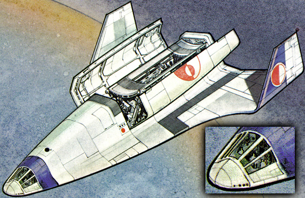
 Lifting your rocket from Terra's surface into circular orbit takes an unreasonably large amount of delta V. As a matter of fact, if your missions use Hohmann trajectories, the lift-off portion will take about the same delta V as does the Hohmann from Terra to the destination planet. As Heinlein put it:


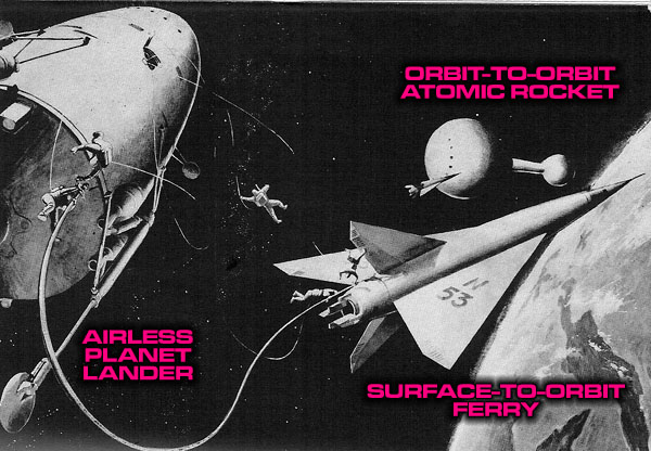


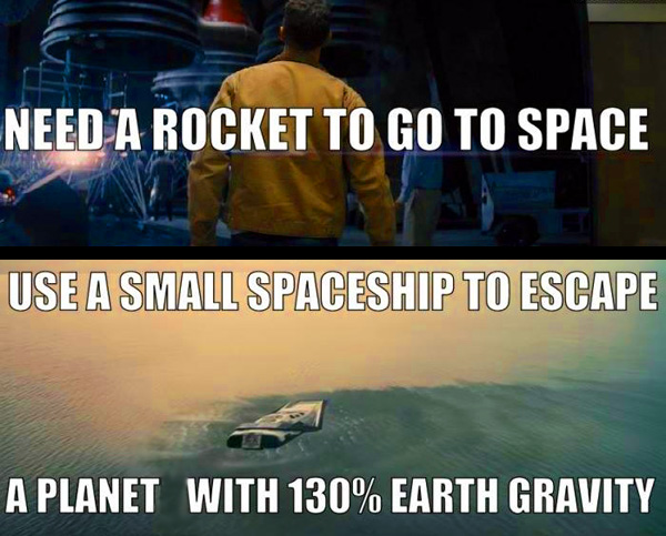
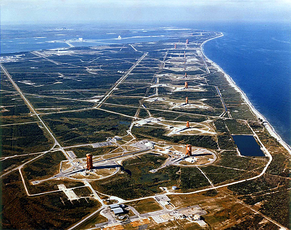


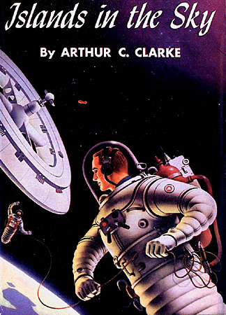
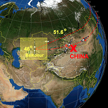


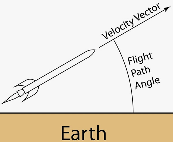
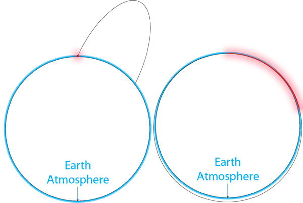
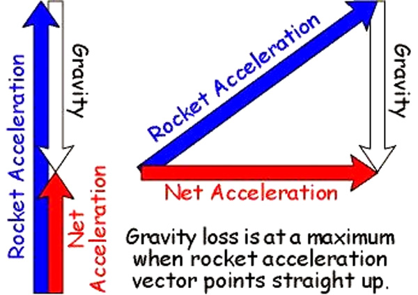
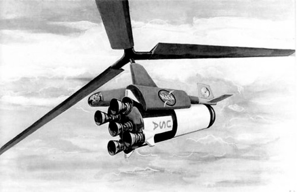
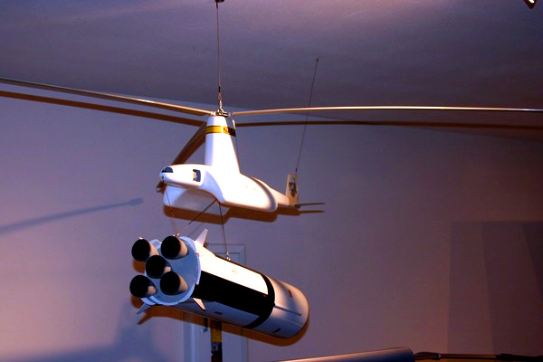
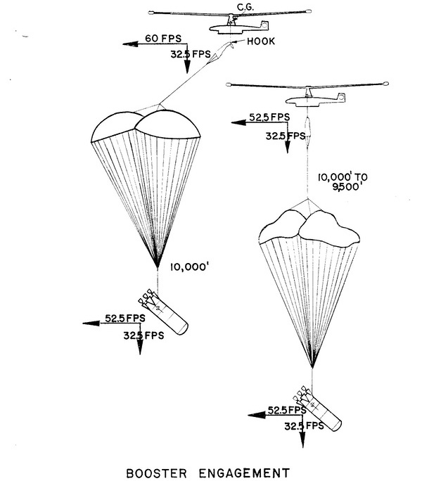
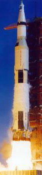
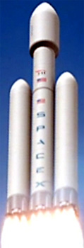
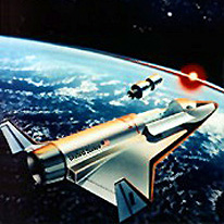


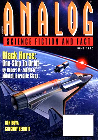
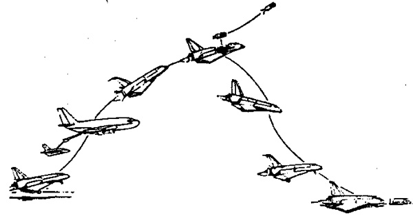
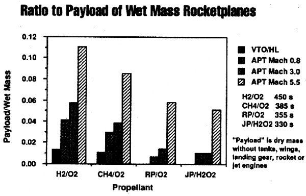
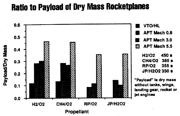
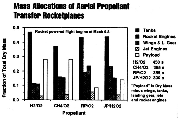
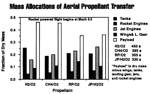
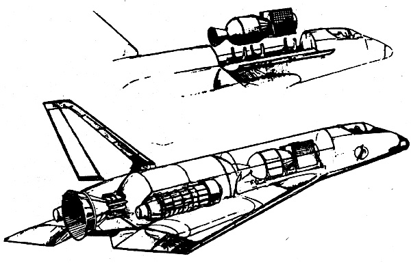
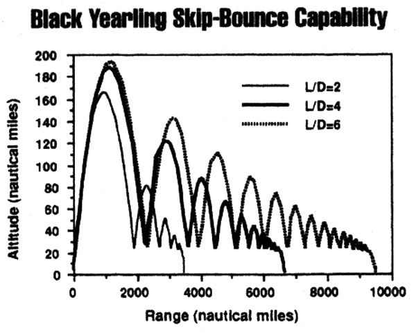
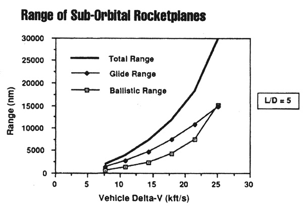
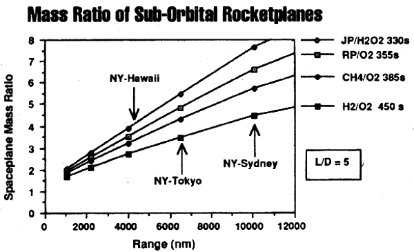
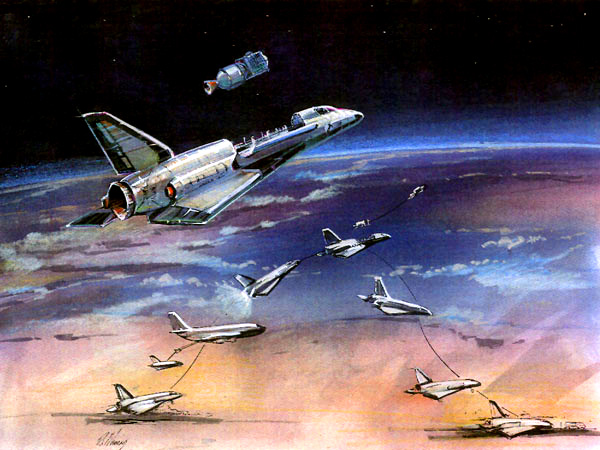
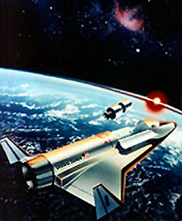
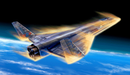
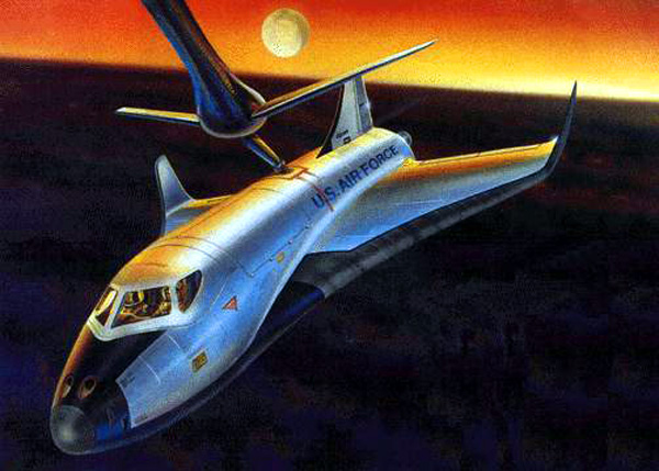
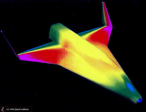
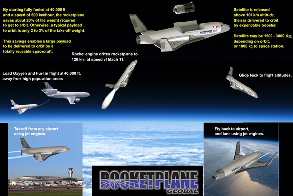
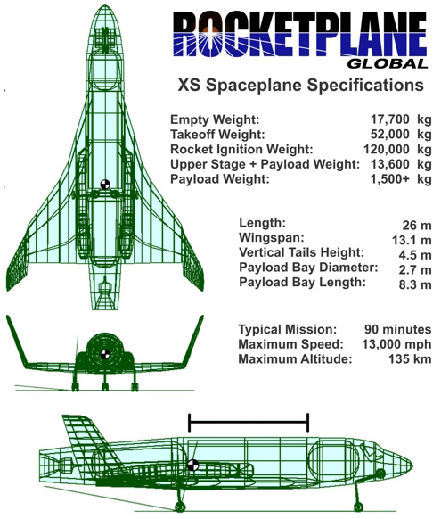
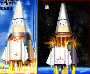


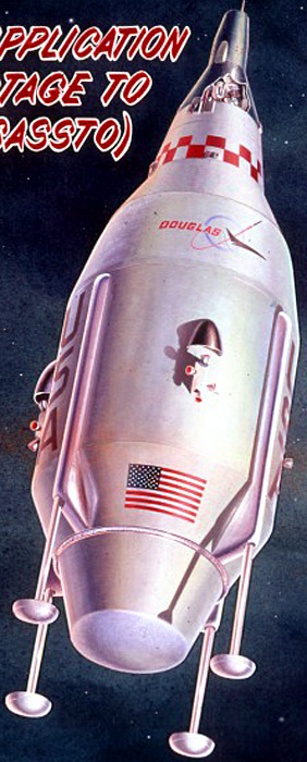
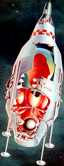
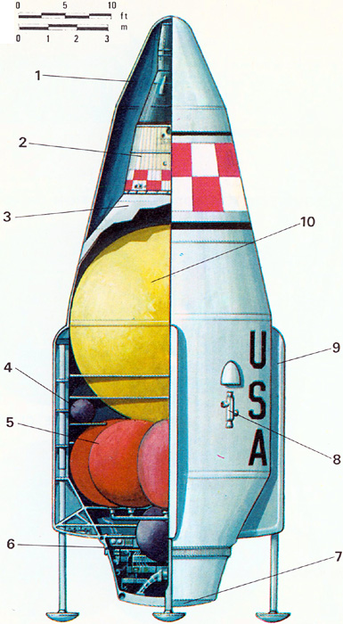
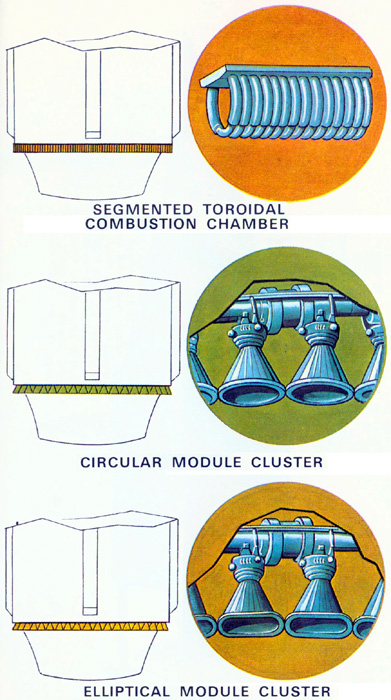
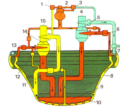
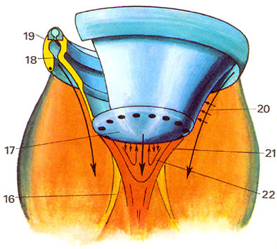
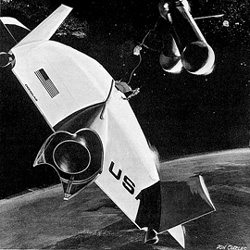
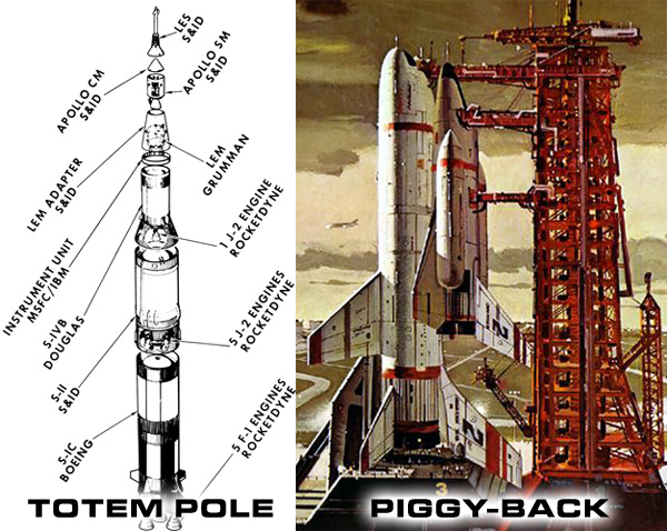


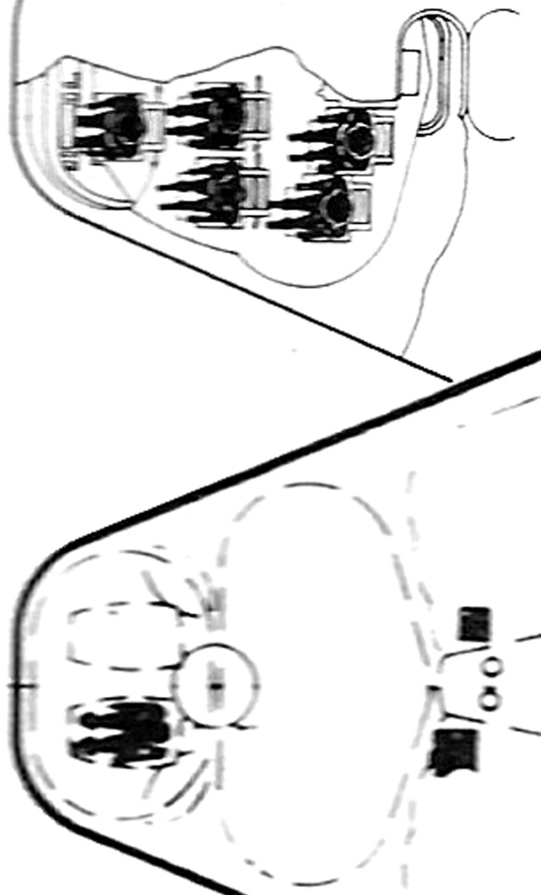


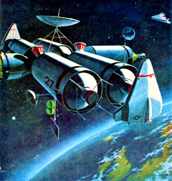


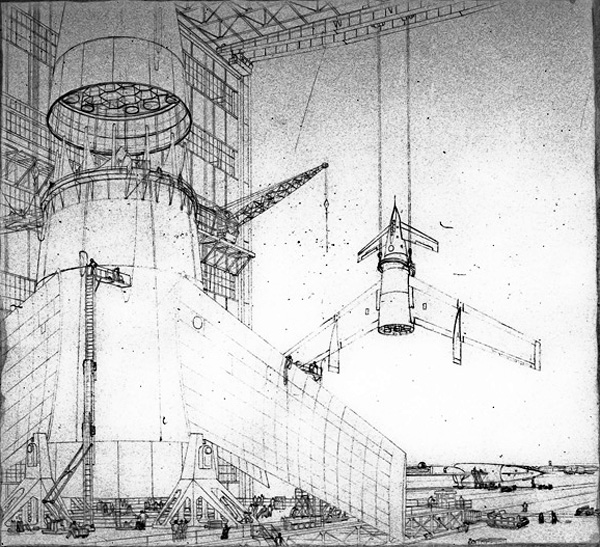
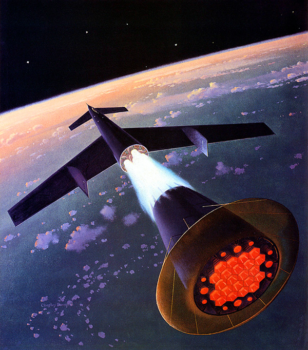
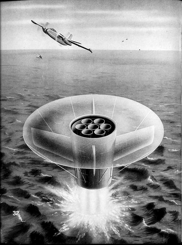
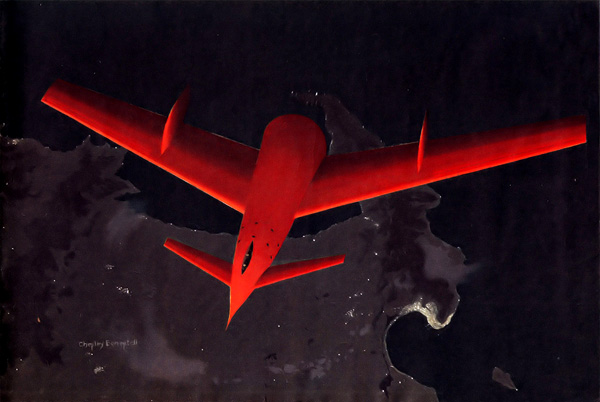


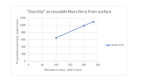
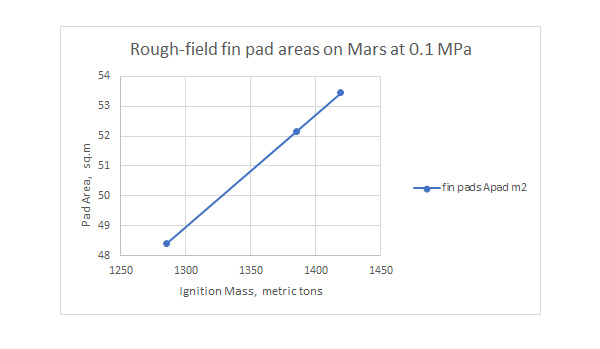
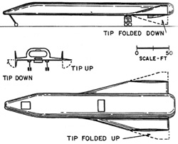

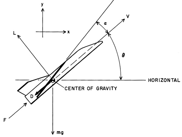
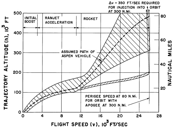
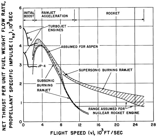
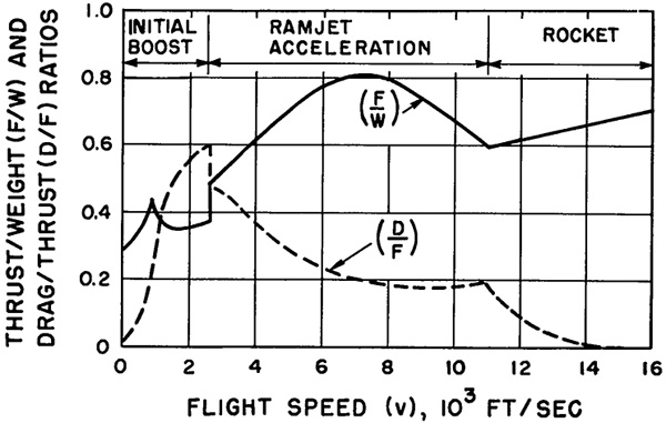
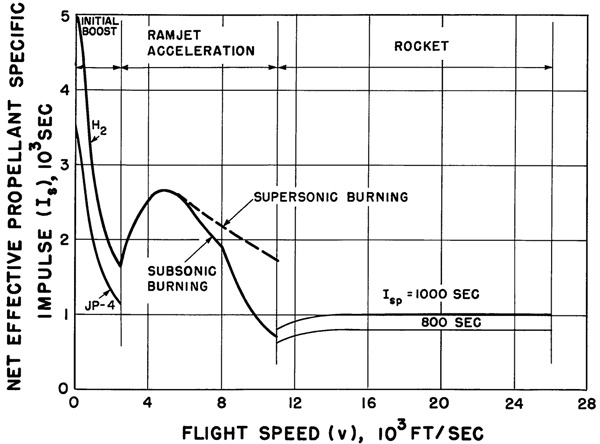
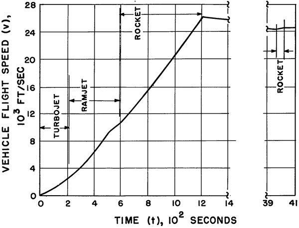
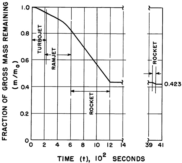
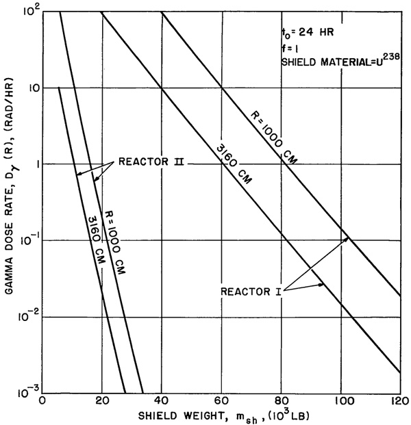

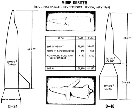


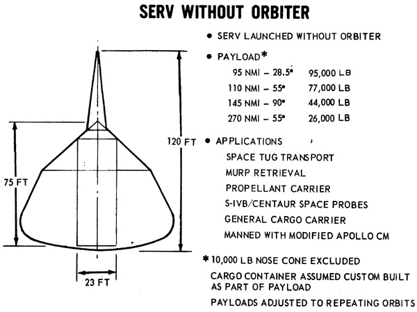
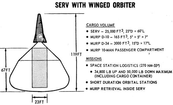
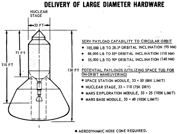
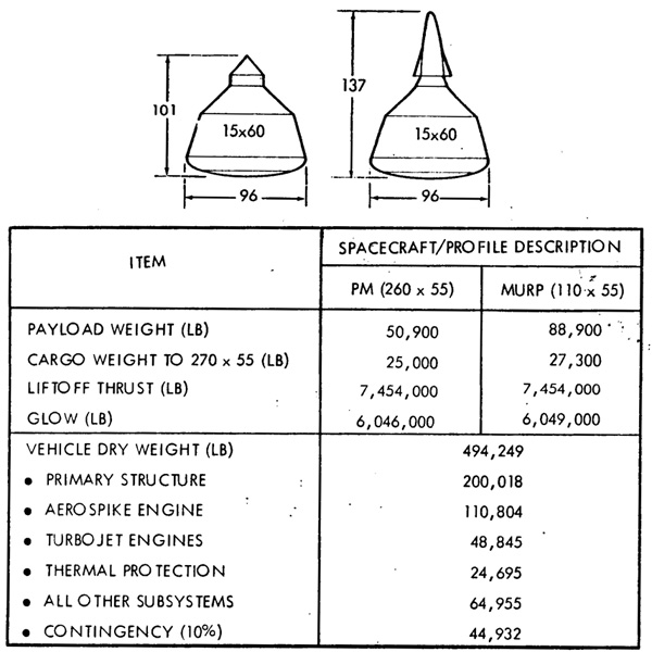
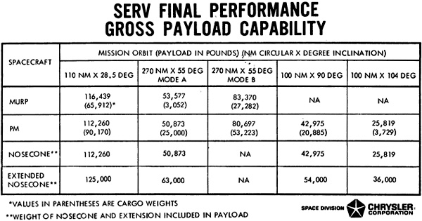

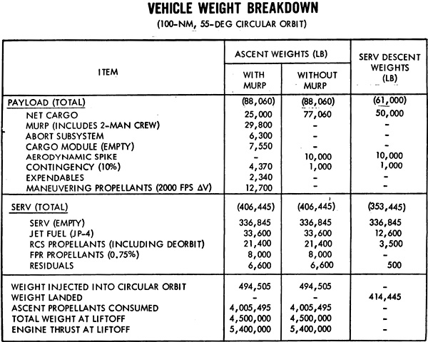
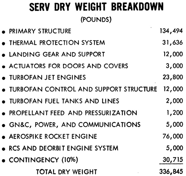

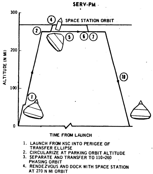
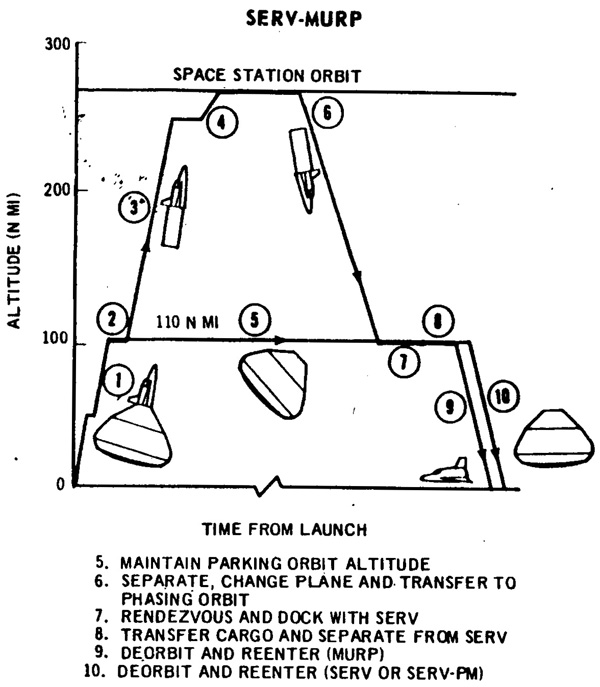
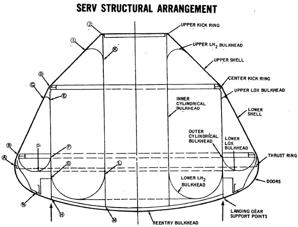
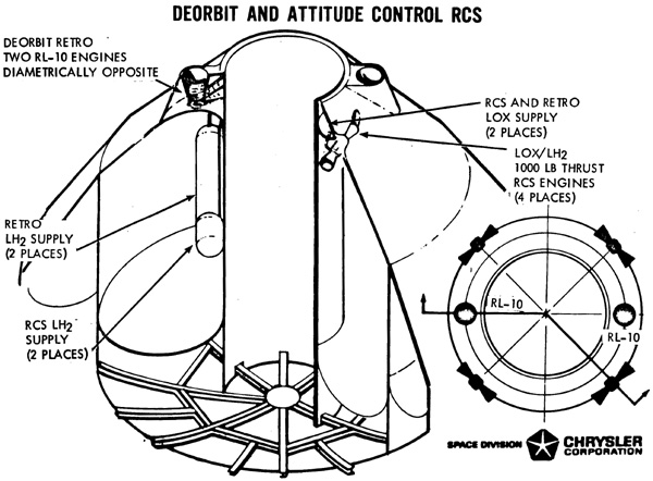

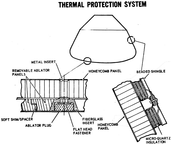

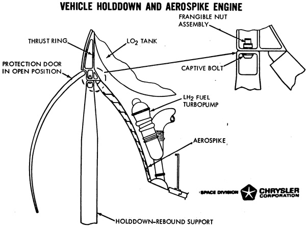
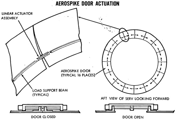

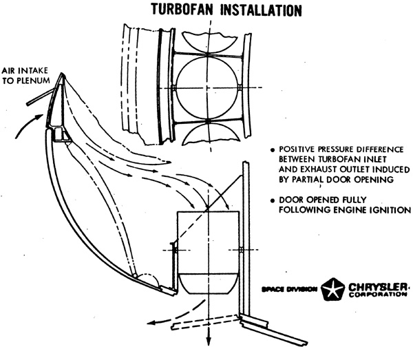


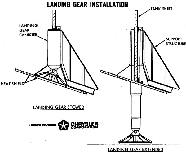

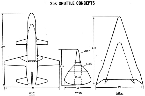


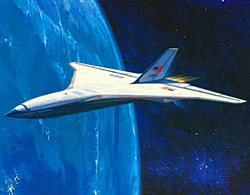
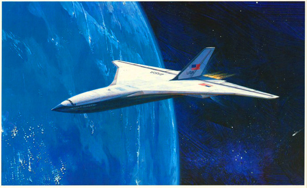
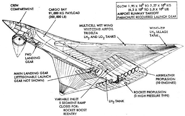

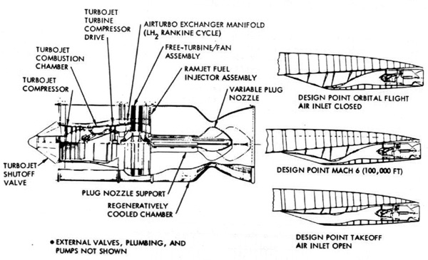
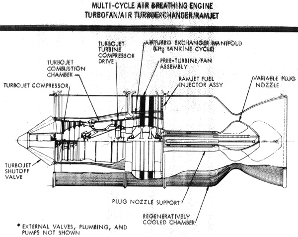
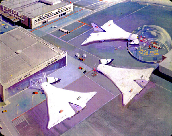
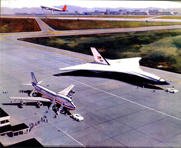

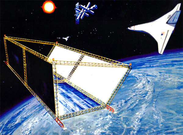
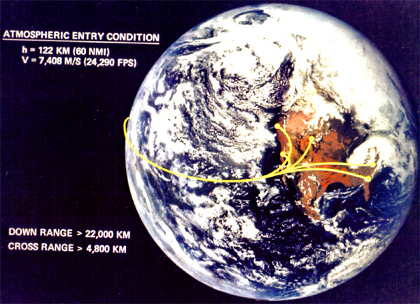

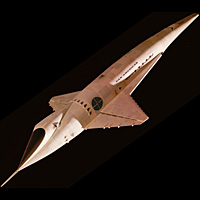
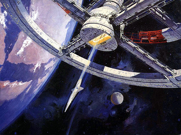
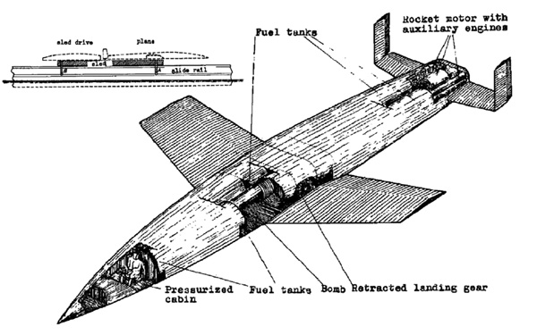
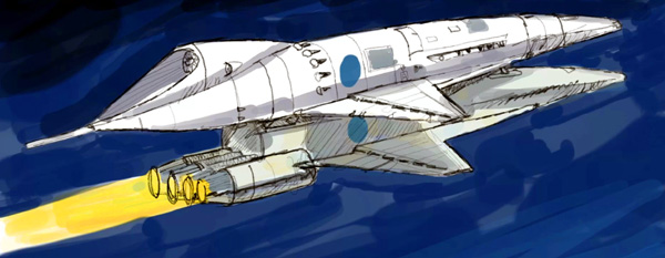
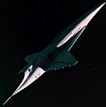
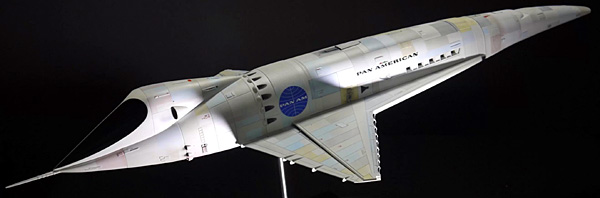
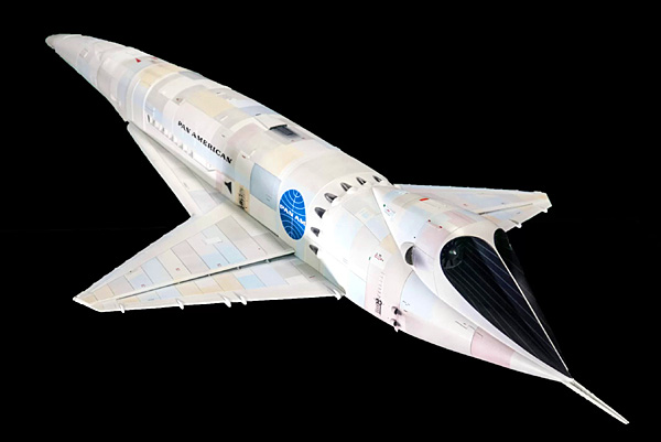
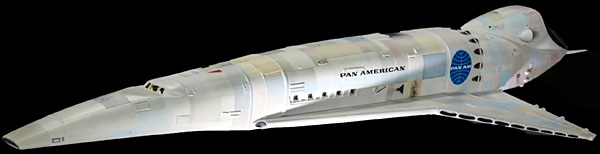
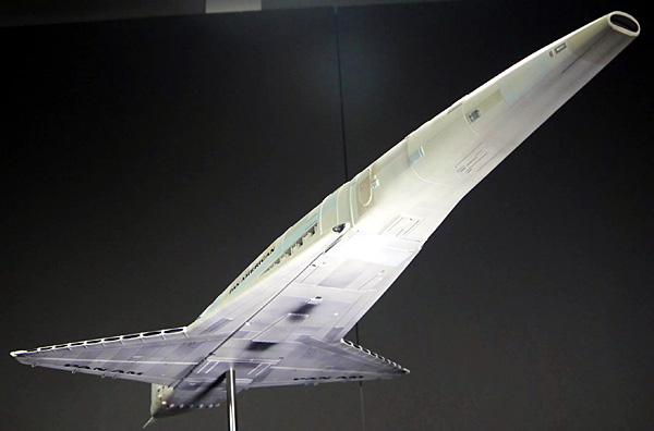
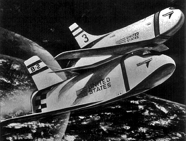
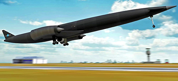

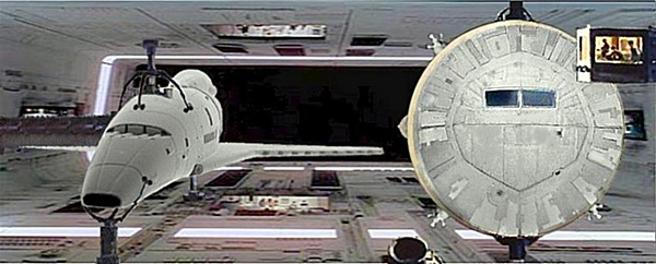

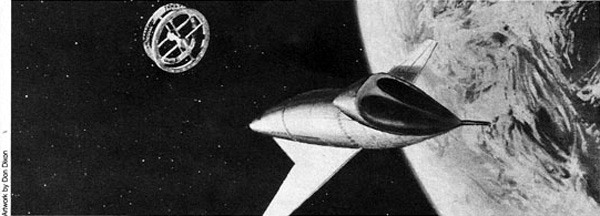
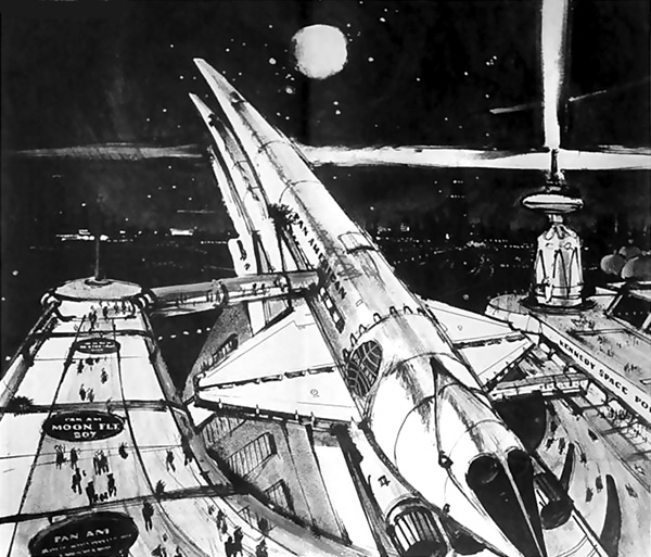
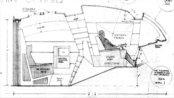
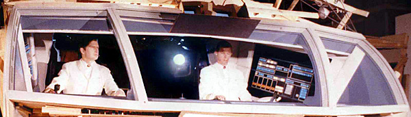
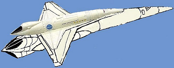
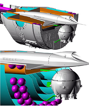
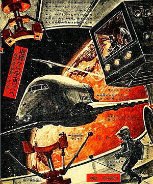
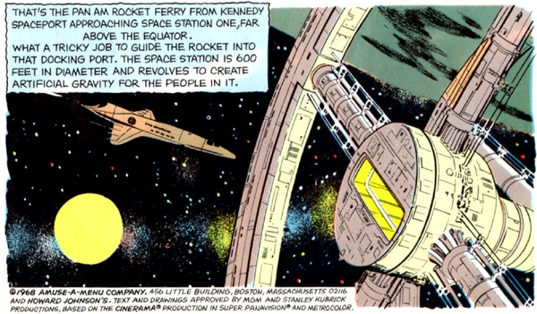
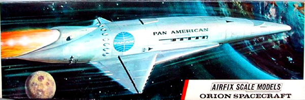
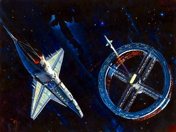
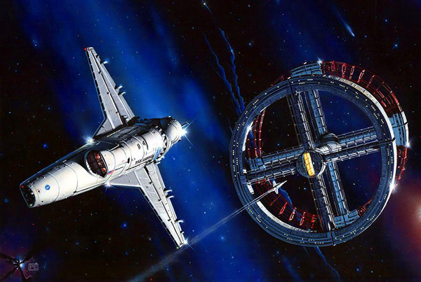
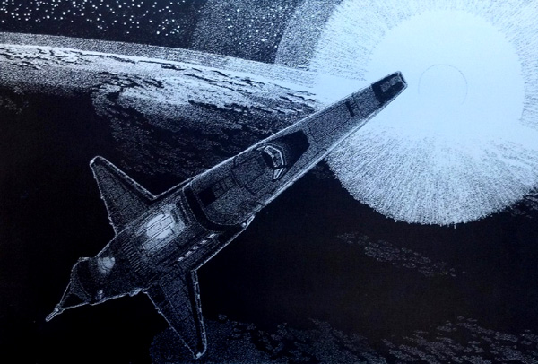
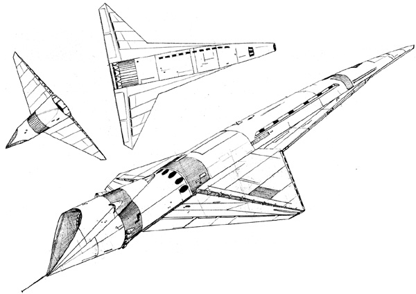


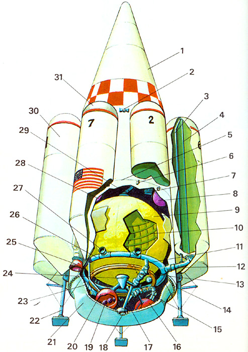
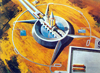
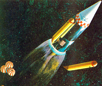


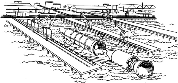
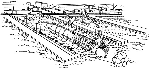
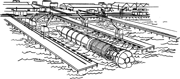


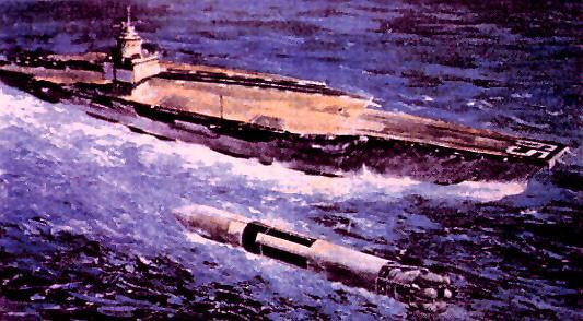
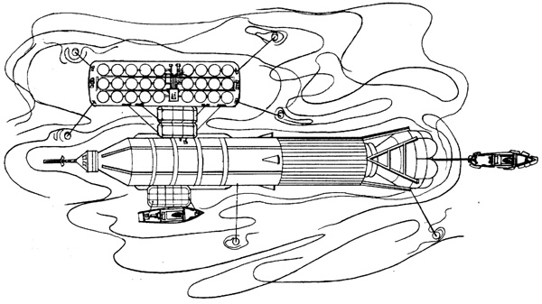
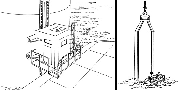
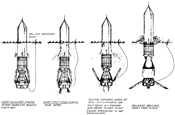


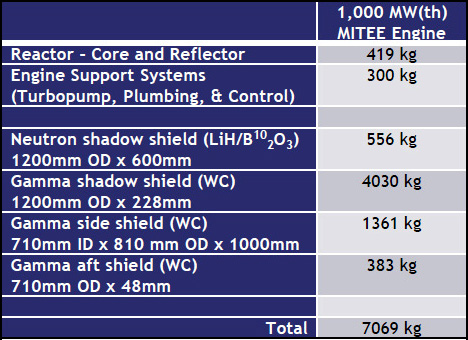
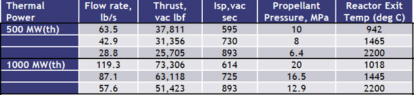
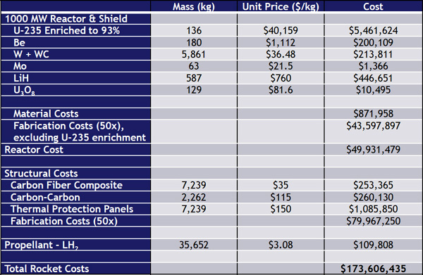
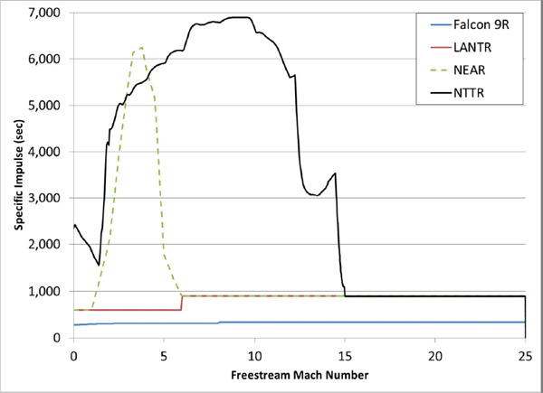
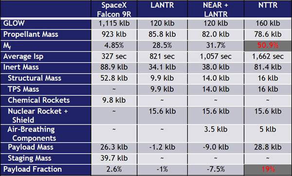


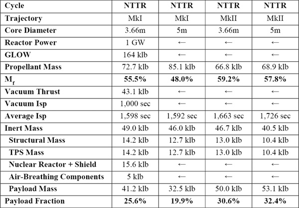
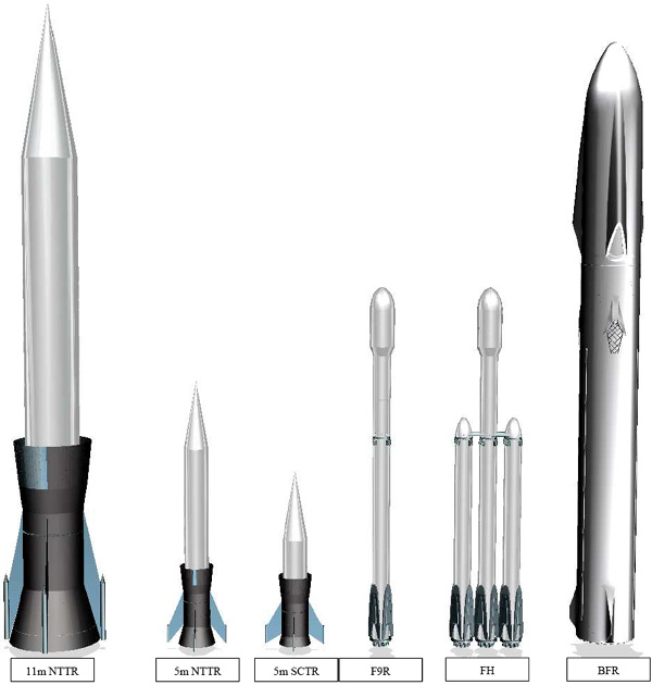

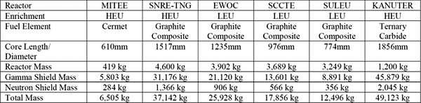
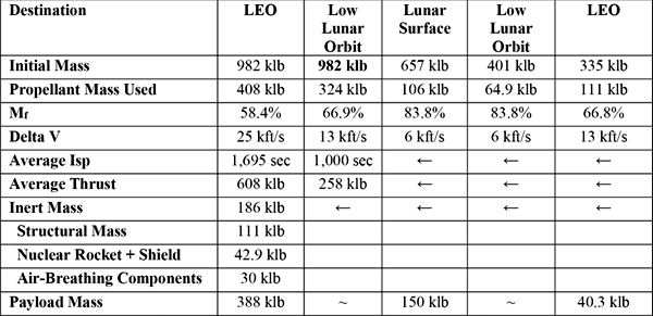
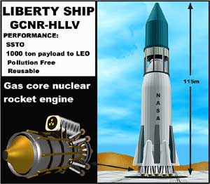
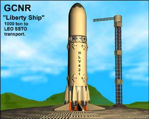


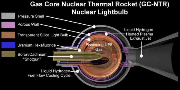

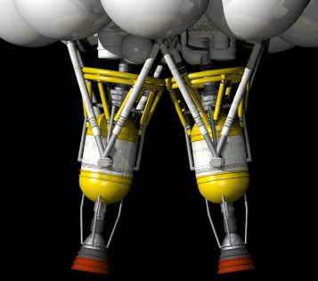


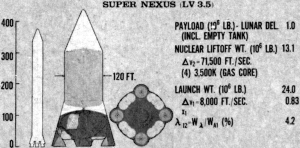


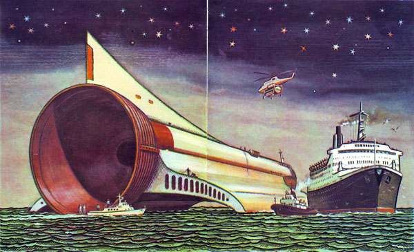


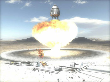
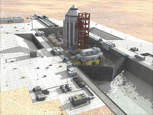
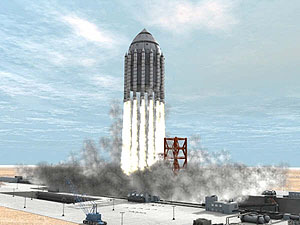
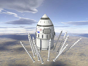
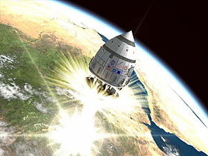

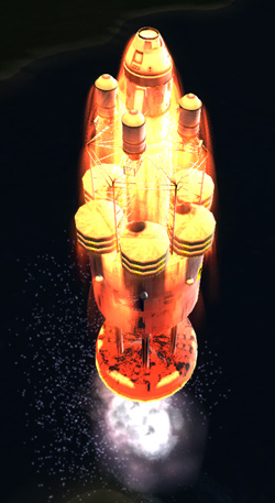

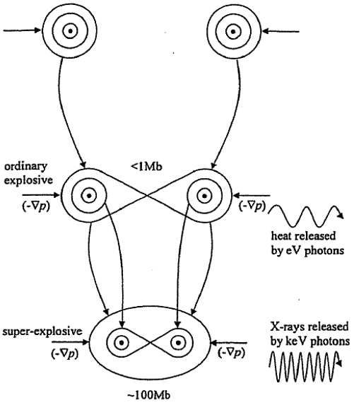
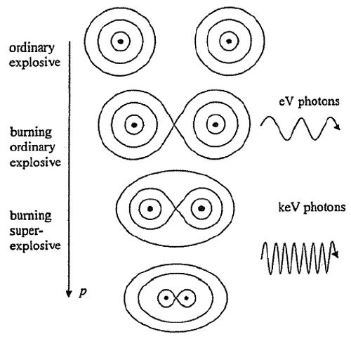


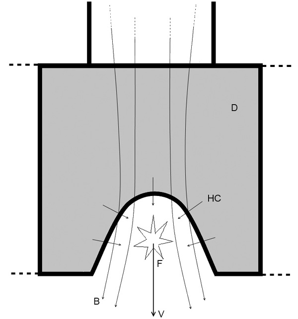

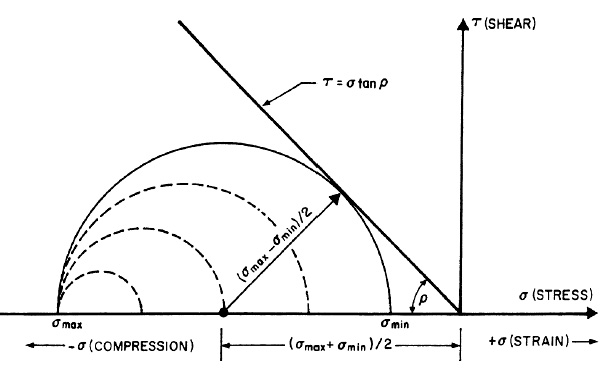

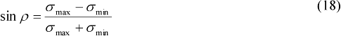
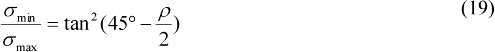


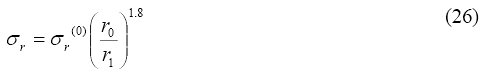
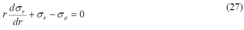
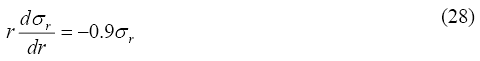
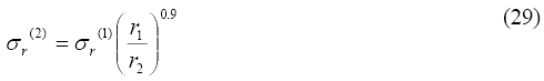
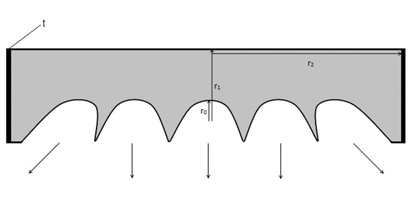

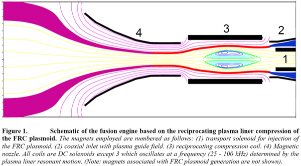
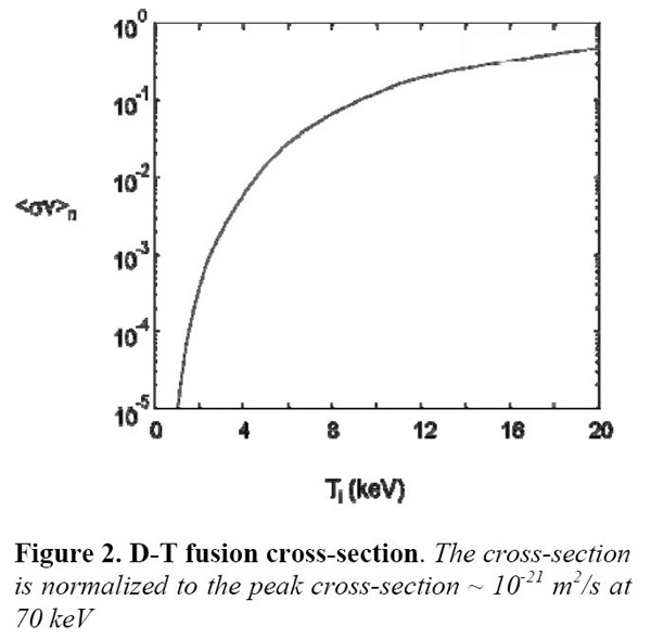


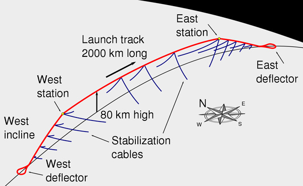
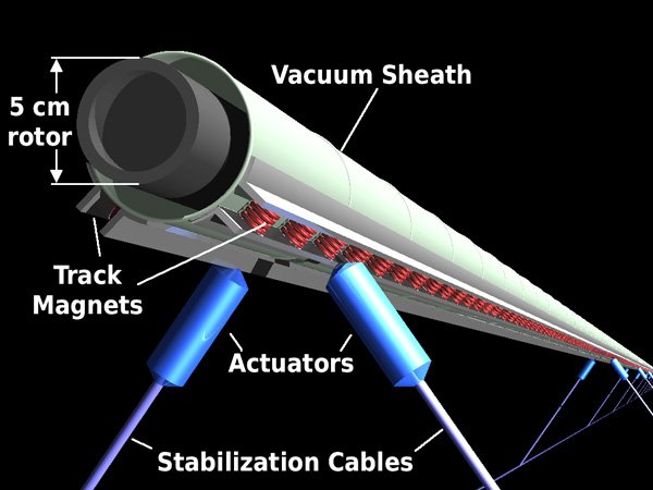
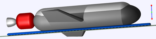
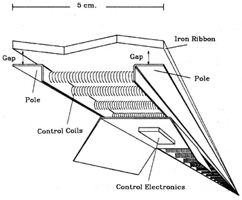

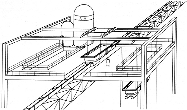
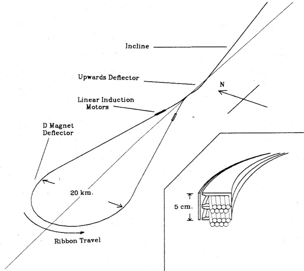
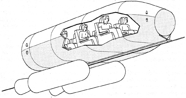
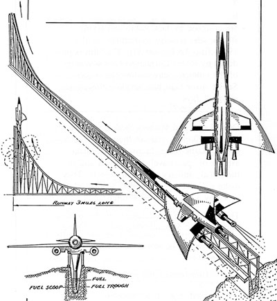
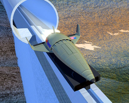
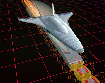

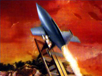
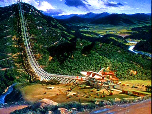
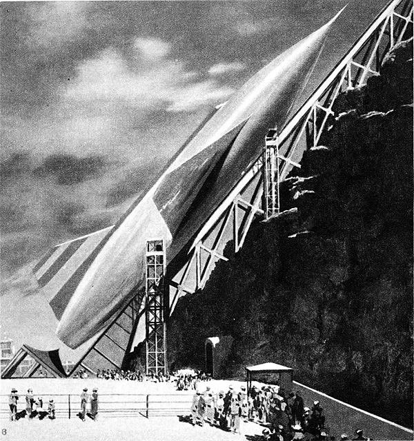

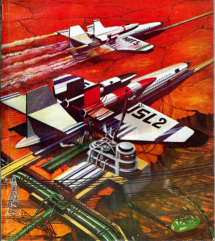
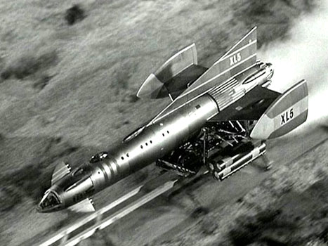


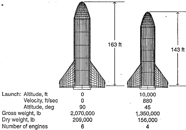
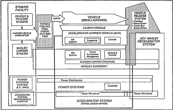
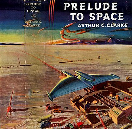
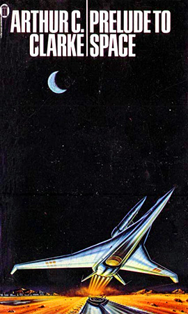

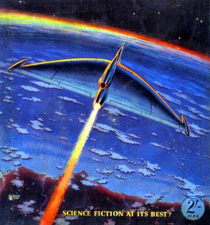

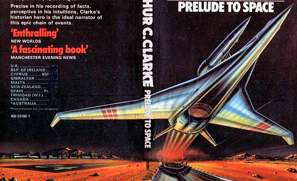
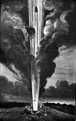

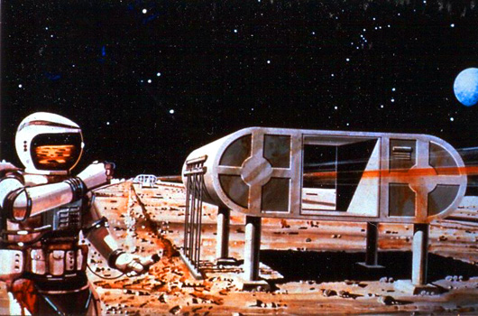


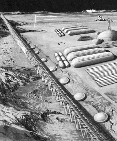

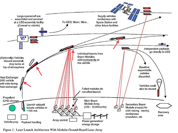
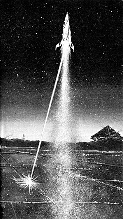
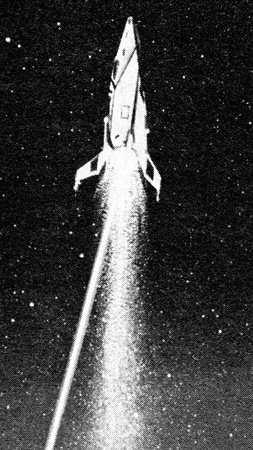


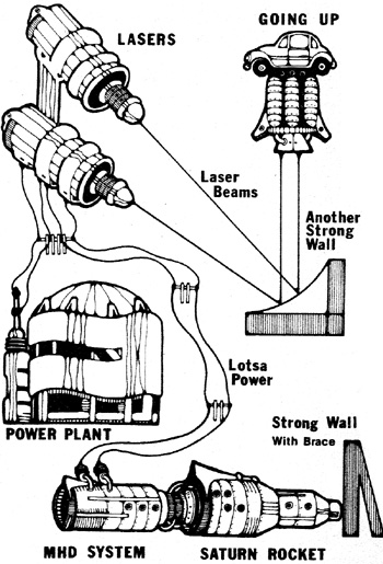

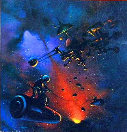
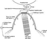

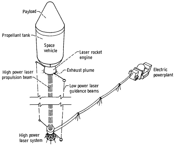


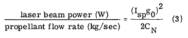
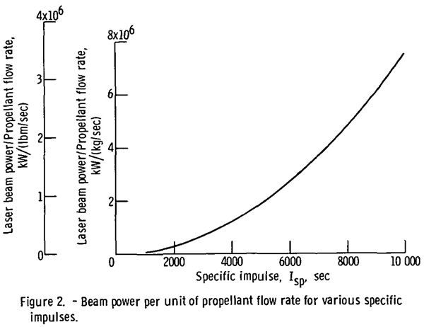
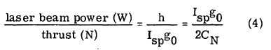
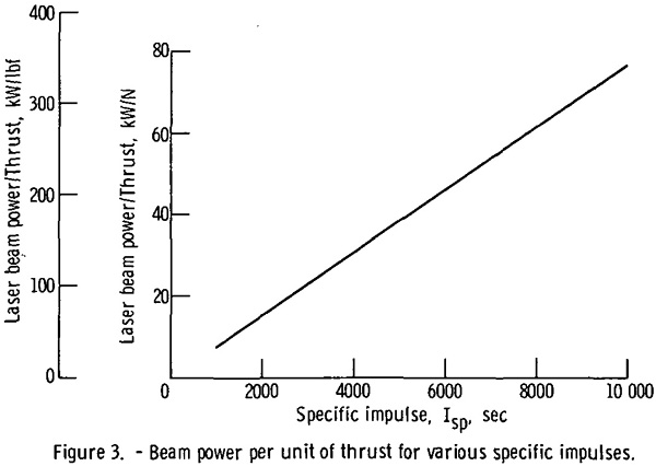
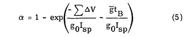

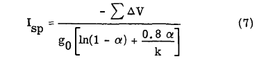
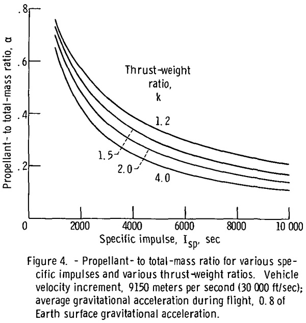

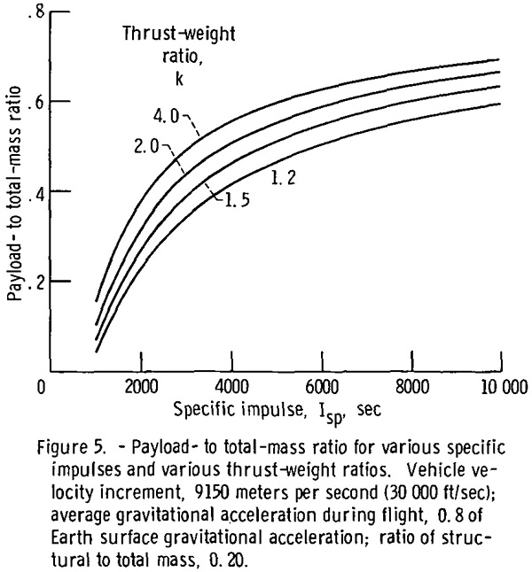
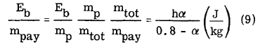
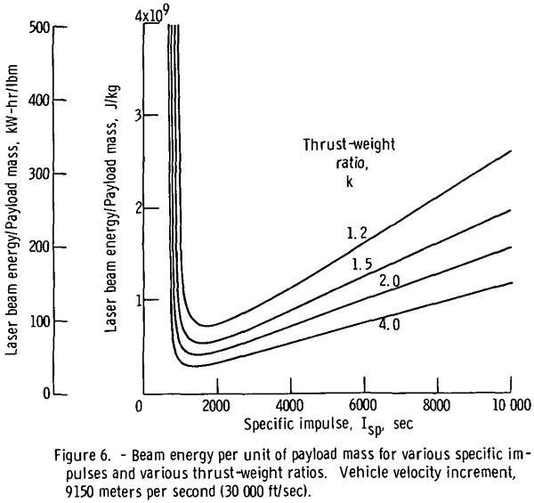
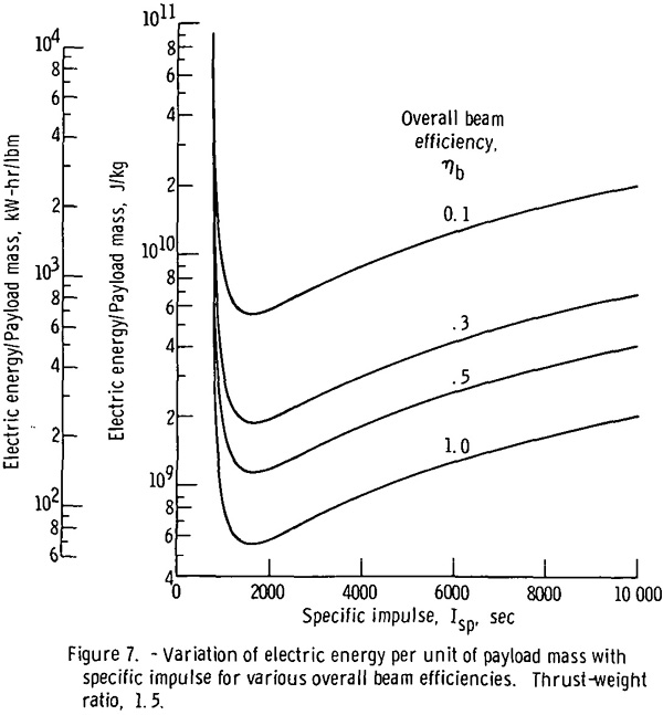
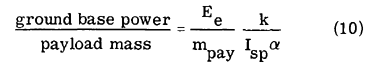
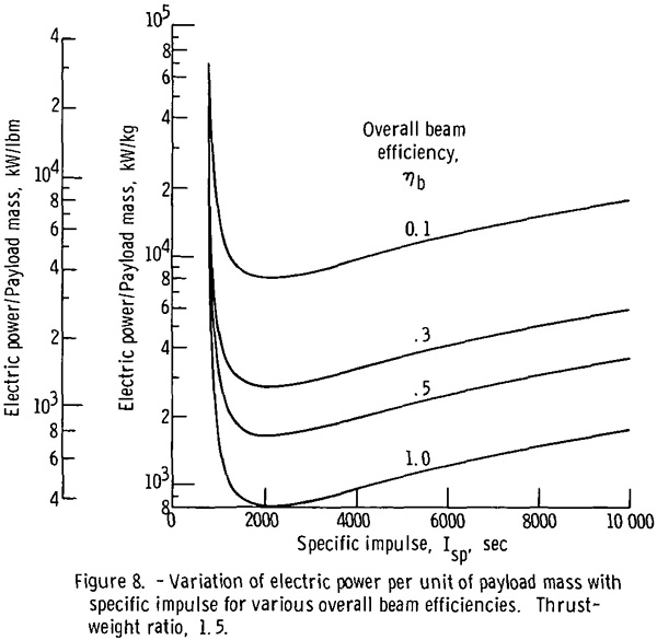
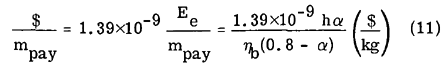
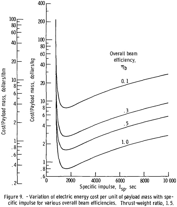
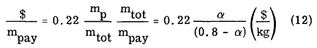
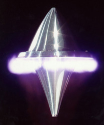
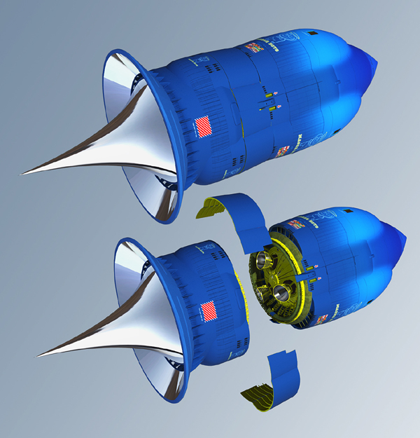

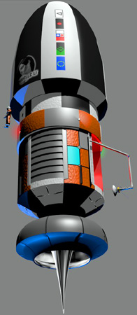
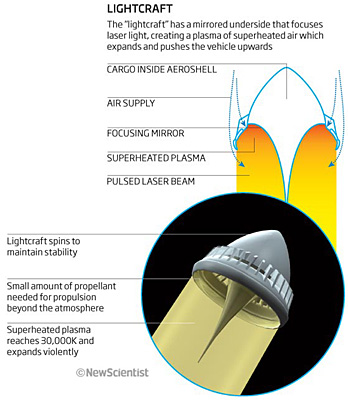
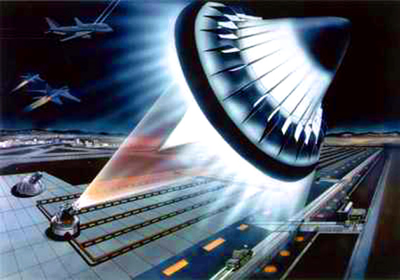
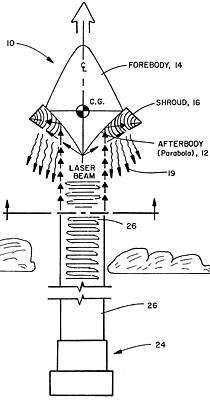
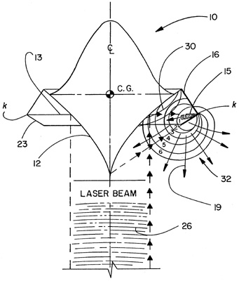
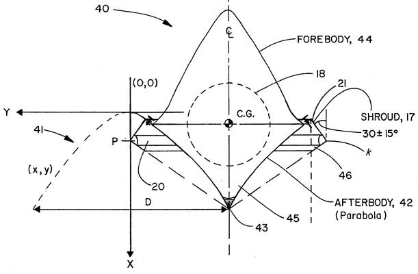
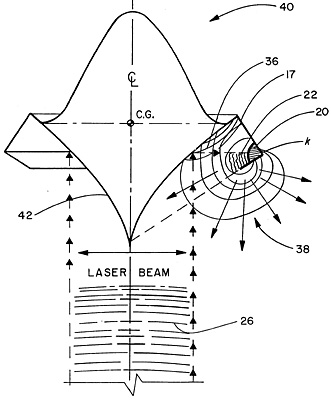
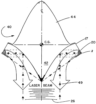
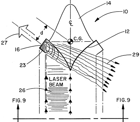
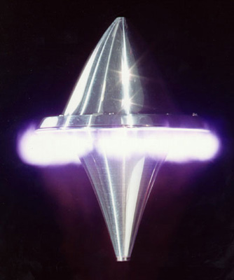
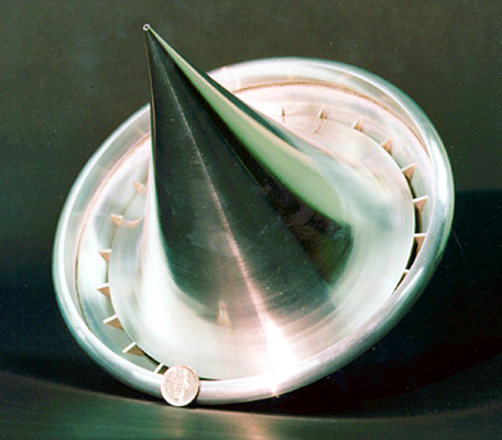

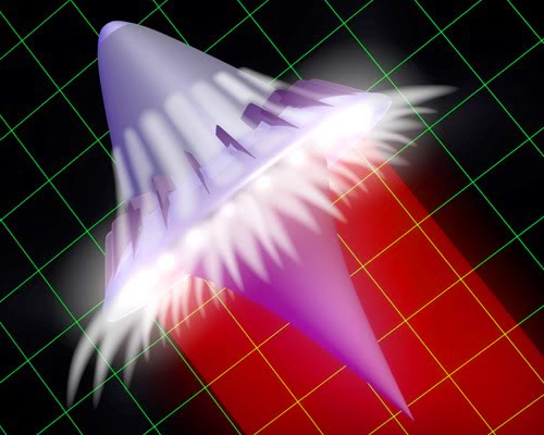
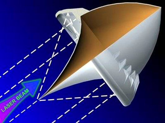
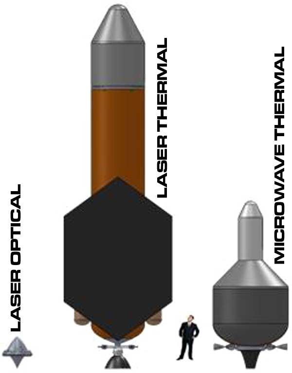
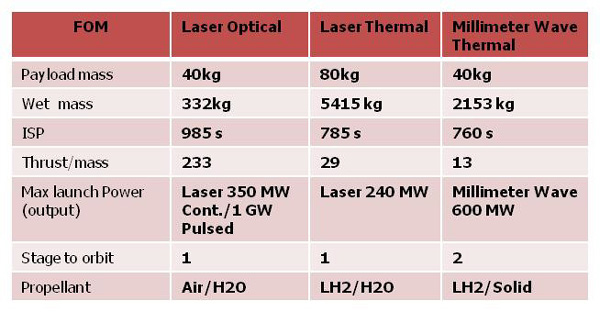
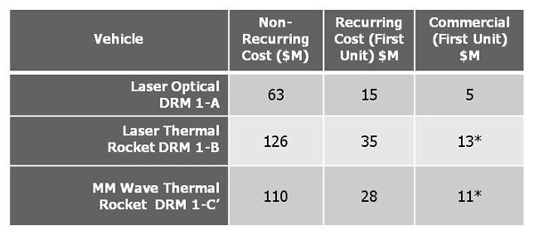
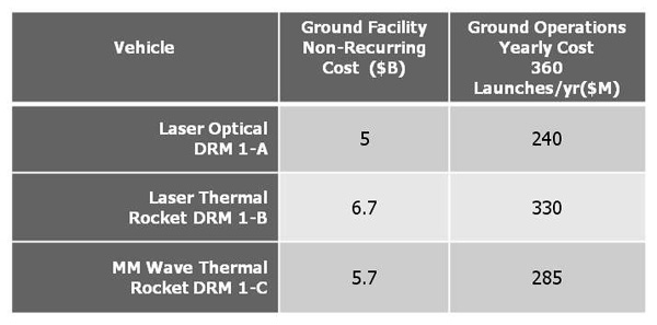
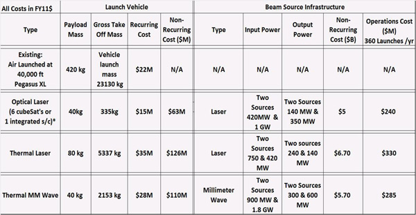

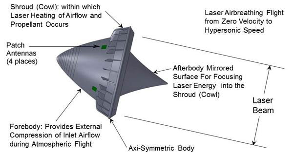
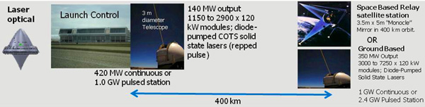
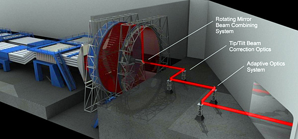


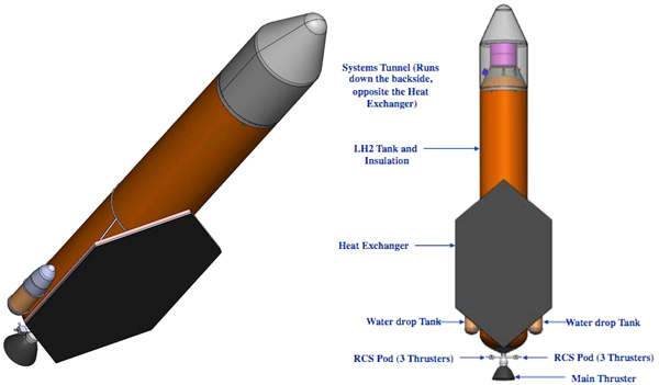
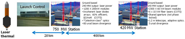
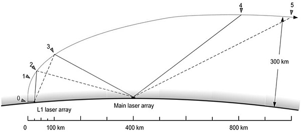
 L1 laser array: the boost beaming station