Many of these spacecraft have a table of parameters. You can find the meaning of many of them here. Numbers in black are from the documents. Numbers in yellow have been calculated by me using the document numbers, these might be incorrect.
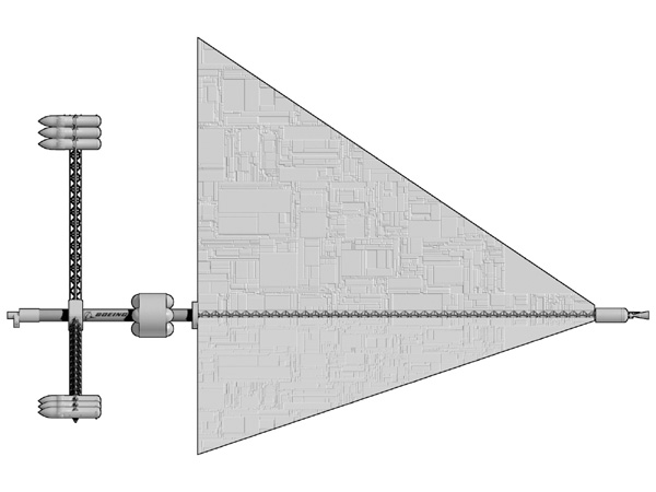
The spacecraft was a fusion powered rocket designed to transport miners to the asteroid belt. 1,250 miners per trip. And a cargo of 150 metric tons.
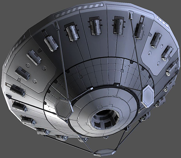
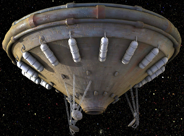
In case it is not clear, the nose of the ship is in the upper left corner, with the tanks on girders. The tail of the ship is in the lower right corner, with the engine.
In the first picture, note the fly-like object in the upper left corner. That looks as if it was supposed to be a 37 meter long Space Shuttle. The pods on the ends of the centrifuge arms may or may not be shuttle external tanks, 47 meters long and 9 meters in diameter.
This thing is freaking ginormous.
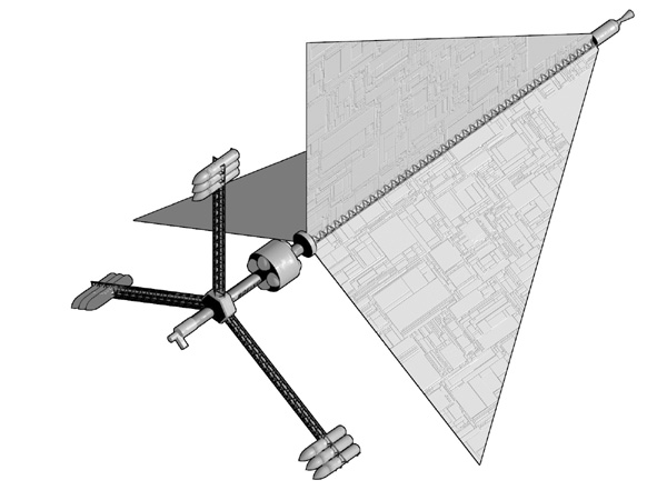
I made a quick and dirty 3D model in Blender and scaled it to with the assumption that the fly in the corner is indeed a 37 meter Space Shuttle. Hard to do since the drawing of the "shuttle" is just a smudge. Reading the dimensions off my model it says the ship is roughly 480 meters long, has a diameter of 400 meters at the tips of the heat radiators, and the centrifuge has a 150 meter radius. Treet these numbers with grave suspicion, they could be off by an order of magnitude plus or minus.
The report Scott found only mentioned the ship in passing, he has filed a FOIA request for another report that might go into more details. I hope so, it would be nice to have some solid figures to work with instead of all this conjecture and assuming.
For the Terra-asteroid run, the vehicle would boost for 11 days, coast for 226 days and brake for 13 days to rendezvous. Adam Crowl calculates if the jet-power is 4.8 GW and the mass-ratio is 5/3 for a return to Earth mission, then an exhaust velocity of ~100 km/s and a total delta-vee of 51 km/s. That means a mass-flow rate of 0.96 kg/s.
There are absolutely huge heat radiators because the engine has to get rid of 2.8 freaking Gigawatts of waste heat.
The heat radiators are triangular, so that they can stay inside the shadow cast by the anti-radiation shadow shield. This is for three reasons:
parts of the radiator extending out of the shadow could scatter deadly radiation onto the passengers
parts of the radiator extending out of the shadow will suffer neutron activation
parts of the radiator extending out of the shadow will suffer neutron embrittlement.
Dr. Luke Campbell points out that the engine is going to need one heck of a shadow shield, because distance attenuation ain't gonna do diddly-squat. Not against 4.4 gigawatts of neutron radiation it isn't. At a measly distance of 480 meters the 4.4 GW of neutron radiation will still be strong enough to give everybody on board the ship a lethal dose of radiation in about 1/5 of a second.
(Doing my own calculation, assuming a person with a body mass of 68 kilograms, a cross section of 0.445 m2, who is 480 meters away from 4.4 GW of neutrons, I figure that with no shadow shield they will be exposed to about 10 grays per second, or a LD35 lethal dose of 2 grays in 1/5 second)
He goes on to say that even with a perfect shadow shield enough neutron radiation would scatter around it if a heat radiator, another spacecraft, space station, or asteroid was outside of the shadow and close to the ship. This can be dangerous over the 12 or so days of continuous thrust (the 226 days between thrust events would probably allow any acute radiation injury to heal — but the chronic stuff will accumulate from different burns).
Dr. Campbell goes on to say that a good shadow shield would probably have an interaction length on the order of a few centimeters at the 2.2 MeV energy of D-D fusion, so a few meters of neutron shielding would reduce the dose by something like 40 orders of magnitude. By way of comparison, the shadow shield on an old NERVA nuclear rocket was only about 0.25 meters thick.
Assuming that the centrifuge arm is indeed 150 meters long, it can spin at a safe no-nausea 2.5 RPM and produce a full gravity of acceleration.
If those pods are indeed Space Shuttle external tanks, they will have an internal volume of a bit more than 2050 cubic meters (the sum of the LH2 and LOX tank). If all of that is passenger volume (meaning the consumables, cargo, life support systems, and everything else is at the ship's spine), then each of the 1,250 passengers will have about 14.8 m3 to call their own for the 8.3 month journey. This is less than the 17 m3 NASA figures the crew needs for missions longer than six months or so. On the other hand, NASA is talking about crew members, not passengers. They are not actually running the ship, so as long as they don't actually start foaming at the mouth and go berserk, 14.8 m3 is probably good enough. Spartan but managable.
Let's fly further into unsubstantiated fantasy, piling shaky assumptions upon shaky assumptions. Do not take these next figures seriously.
Assuming my hasty 3D model based on a crude sketch is anywhere near accurate, my modeling package says that one of the triangular radiators has a surface area of about 6,400 square meters (counting both sides). This means the entire radiator array has a total radiating surface area of about 19,200 square meters.
This has to cope with the 2.8 gigawatts of heat.
Say that the heat radiators are titanium-potassium heat pipes. These have a specific area heat of 150.22 kWth/m2, so to handle 2.8 GW it will take about 18,640 m2. This is less than the model's radiator area of 19,200 m2 so we are in good shape.
Ti/K heat pipes have a specific area mass of 100.14 kg/m2 so 18,640 m2 worth would have a mass of 1,866,600 kg. This is less than the propulsion bus mass of 2,000,000 kg so we are in good shape.
This means the propulsion bus has 133,400 kg left for the engine and structure. Sounds reasonable to me. But again all of this is fantasy, done for amusement value.
In the data block, the figures in black are from the report, the yellow figures are deduced. Treat the yellow figures with some skepticism.
Figure 4-11a click for larger image
Hasty 3D model I threw together in order to get an idea of the size. I'm assuming that the modules at the tips of the centrifuge are Space Shuttle external tanks. Shaky assumptions all. click for larger image
Figure 4-11b click for larger image
My hasty 3D model
My hasty 3D model
My hasty 3D model
Figure 4-12 click for larger image
4.5 Asteroid Base
The mission assumes an asteroid mining operation with a 5000 person habitat. The complex transportation scenario for this advanced mission involves four different vehicles and three separate space bases (refs. 86 and 91).
c. The GEO base serves as the final assembly area for the large fusion rocket system
used to propel payloads out to the asteroids. Cargo and propellant are unloaded
from electric-powered transfer vehicles sent up from the LEO base. The enlarged
OTV used to transfer personnel and priority cargo is designed to transport 441,000 lb
(200,000 kg) from LEO to GEO. The complex fusion propulsion system is assembled
at the base with the fusion power core, propellant tanks, large thermal radiators,
and the personnnel and priority cargo modules. The resulting vehicle, shown in
figure 4-11, can transport 1250 passengers and 150 metric tons of priority cargo to
the asteroids.
The gross start mass for the resupply mission would be 10,000 metric tons, of which power plant comprises 2000 tons; hydrogen propellant, 4000 tons; and payload, 4000 tons (1250-person habitat plus consumables and priority cargo). The power plant consists of two 6 GW fusion reactors utilizing the deuterium-deuterium fusion reaction. The total power plan provides 4.8 GW of thrust power while radiating almost 2.8 GW of waste heat and 4.4 GW of high energy neutrons.
d. There are two methods the fusion rocket will use to propel vehicles to the asteroid
base: fast transfer for personnel and priority cargo, and slow transfer for
nonpriority cargo. The manned resupply mission is a fast hyperbolic transfer orbit
consisting of an 11-day thrust period to achieve hyperbolic velocity, followed by a
226-day coasting, and a 13-day deceleration to match velocity with the asteroid
base. The return mission leaves the asteroid approximately 113 days later for a
reverse of the ascent mission.
The second method is used to accelerate unmanned cargo pods on a slow elliptical (Hohmann) transfer orbit out to the asteroid base. Figure 4-12 illustrates the different trajectories. The slower trip takes 130 days longer but costs less than half of what the fast, hyperbolic trip costs. All nonpriority cargo is brought to the asteroid facility in this manner. Empty cargo pods are not returned to Earth, they may be discarded or used in a variety of ways as storage modules or Closed Ecological Life Support System (CELSS) modules.
e.A fleet of two fusion rockets is envisioned. They each make one round trip per asteroid orbit (synodic cycle) to the asteroid mining facility and leave a few days apart. Because of the synodic cycle, the fusion rocket vehicles are delayed at the asteroid base for approximately 113 days, at the GEO location they are delayed approximately 288 days. During these delays the fusion rockets are used to decelerate unmanned cargo pods at the asteroid base and to accelerate the pods at GEO. Cargo pod launches are timed to arrive at the asteroid base shortly after the manned resupply vehicles so that the fusion rockets can decelerate the cargo pods. The rendezvous opportunity (synodic cycle) repeats itself every 928 days. This transportation system allows half of the total crew to be rotated each cycle.
86. Advanced Propulsion Systems Concept for Orbital Transfer. 1981. NAS8-33935.
This should happen more often. A team of rocket scientist at the Glenn Research Center were inspired by the Discovery from the movie 2001. So they designed one with modern technology that would actually work!
Discovery II
ΔV
223,000 m/s
Specific Power
3.5 kW/kg (3,540 W/kg)
Thrust Power
3.1 gigaWatts
Propulsion
Helium3-Deuterium Fusion
Specific Impulse
35,435 s
Exhaust Velocity
347,000 m/s
Wet Mass
1,690,000 kg
Dry Mass
883,000 kg
Mass Ratio
1.9
Mass Flow
0.080 kg/s
Thrust
18,000 newtons
Initial Acceleration
1.68 milli-g
Payload
172,000 kg
Length
240 m
Diameter
60 m wide
This design for a fusion propulsion spacecraft is from the NASA report TM-2005-213559 by Craig H. Williams, Leonard A. Dudzinski, Stanley K. Borowski, and Albert J. Juhasz of the Glenn Research Center (2005). The goal was to produce a modern design for the spacecraft Discovery from the movie 2001 A Space Odyssey. The report has all sorts of interesting details about where the movie spacecraft design was correct, and the spots where things were altered in the name of cinematography. The movie ship had no heat radiators, and the diameter of the centrifuge was too small. Arthur C. Clark was well aware of this, but was overruled by the movie people.
Video clip of Discovery II Animation by f r a g o m a t i k click to play video
Note the Thrust Augmentor at the end of the engine. This allows the engine to shift gears, trading off trade thrust for exhaust velocity (specific impulse) and vice versa. It is used for similar reasons that one would downshift with an automobile. In the case of the rocket if it is currently deep in a gravity well, one can increase thrust so you can get out of the well quick and stop paying its per-second gravity tax. The cost is a lower exhaust velocity (which means bad gas mileage) but in this case it is worth it. The Thrust Augmentor shifts gears the standard way, injecting cold hydrogen propellant into the hot exhaust.
The values for acceleration assume a fully fueled spacecraft with a mass of 455,000 kg.
mDot is propellant mass flow in kg/sec, it is equal to thrust divided by exhaust velocity.
Multiply mDot by the duration of the engine burn (in seconds) to calculate how much propellant was expended.
The report gave an example of shifting gears.
Say the spacecraft starts deep in Terra's gravity well in NEO (in a 1.5 hour orbit). If it used high gear (exhaust velocity 450,000 m/s) it would have a pathetic thrust of 445 Newtons, and would take forever to move out of NEO with a miniscule acceleration of 0.0000997 g. Instead it down-shifts to low gear (exhaust velocity 45,000 m/s) for a brawny thrust of 4,450 N. The relatively huge acceleration of 0.001 g will have the spacecraft out of the gravity well in 26.5 hours flat ("out of the well" defined as local parabolic velocity at 28 Earth radii distance). The drawback is it will burn 95 metric tons of propellant but you can't have everything (otherwise you'd have a mythical torchship in your hot little hands). At this point your ship is 95 tons lighter (new mass of 360,000 kg) so the instantaneous acceleration is up to 0.00127 g.
Since the ship is now basically in Sol's heliocentric gravitational field (0.0006 g) it can safely upshift into high gear fuel economy mode. Thrust of 890 N, exhaust velocity of 225,000 m/s. This will accelerate the spacecraft to solar parabolic velocity (42 km/s) in about 60 days, burning about 8 metric tons of propellant and moving the spacecraft a distance of 1.1 AU.
If you now set the engine to "idle" and just coast, you will cross the orbit of Mars in 60 days flat, and the orbit of Jupiter in 300 days. This is just for illustration, you will zip by both planets at 42 km/s. If you actually wanted to be captured into orbit you'd have to do a braking maneuver.
Given a requirement of 37,000 m/s delta V and heavy use of low gear (exhaust velocity 45,000 m/s) I calculate a mass ratio of about 2.3, if my slide rule isn't lying to me. The report didn't go into such details.
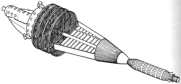
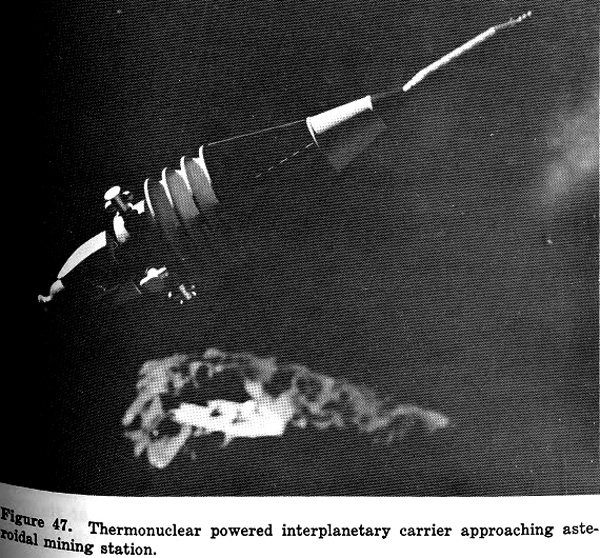
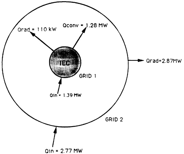
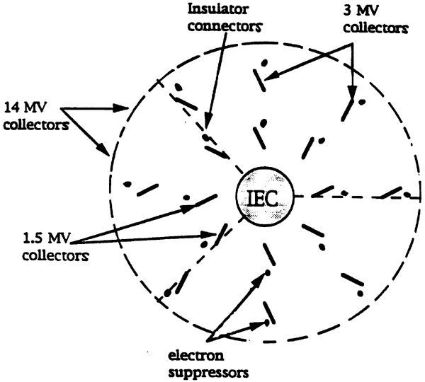
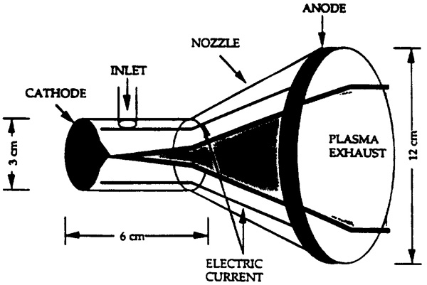
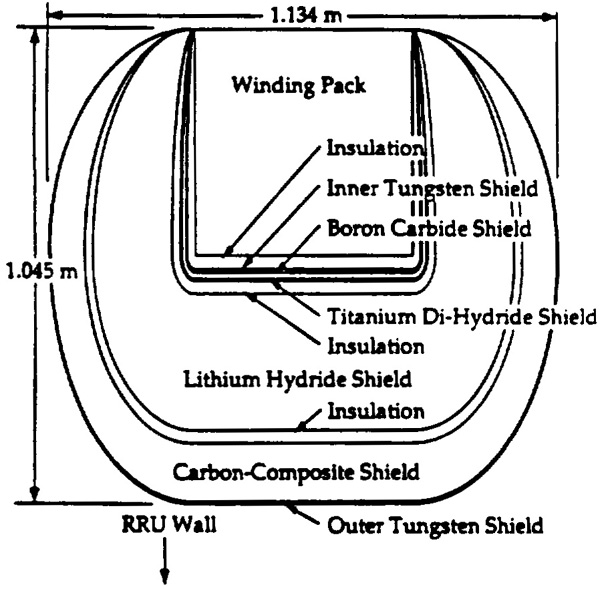
Controlled Thermonuclear Reactor Vehicle Concept
100 megawatt jet power
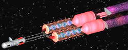
click for larger image
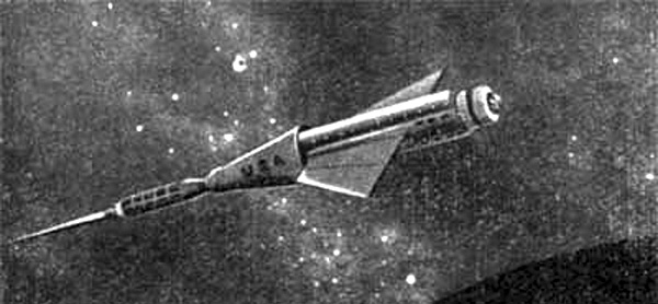
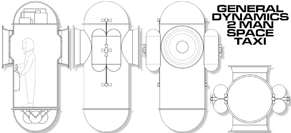
The spacecraft also has four of those adorable space taxis.
1964 General Dynamics space taxi. One man version ~2.8 meters tall. Artwork by Scott Lowther
Design by Krafft Ehricke. From Volume 10: "Space Age in Fiscal Year 2001". Proceedings of the Fourth AAS Goddard Memorial Symposium, 15-16 March 1966, Washinton DC. Published by American Astronautical Society.
This was designed by Seth Pritchard; physics student, SF author, and SF artist. You may have noticed some of his work in other places on this website.
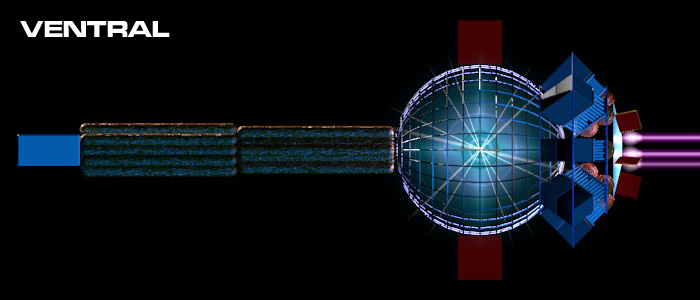
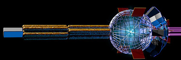
The spacecraft is a cargo hauler, using a second-generation fusion engine. As Mr. Pritchard notes a D-3He reaction theoretically does not emit deadly neutron radiation, except for those pesky side-chain reactions. So you need an anti-radiation shadow shield anyway. The large heat radiators are trimmed to keep inside the safe shadow to avoid backscattering neutrons on to the ship.
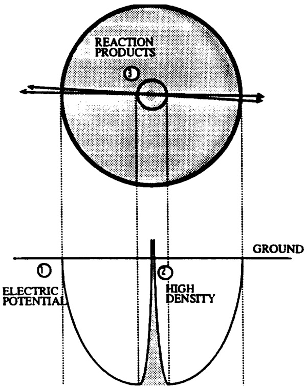
Isaac Kuo notes that shadow shown is not quite correct and I suppose he has a point. The shadow cast (indicated by the radiator chopped bits) by the shadow shield (object I in diagram below) implies that all the neutron radiation is coming from the center of the fusion reaction (object F in diagram below). Isaac points out that neutrons will bounce off anything, including the long exhaust plume. They can be emitted from the reactor, travel aft, hit the exhaust plume, bounce forward, and due to their acute angle they can miss the shadow shield but still hit the radiators.
This can be addressed by increasing the diameter of the shadow shield and/or increasing the distance from the engine and the rest of the spacecraft by lengthening the spine (putting the engine at the end of a long boom). In other words this is just a minor design detail, not a show-stopper.
Specific impulse is gear-shifted to adjust to optimum for the delta-V requirements of current trip. Gear-shift is performed by adjusting rate of cold remass injection.
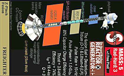
The automated freighter "Electric Magnolia" lights its fusion drive near the main belt asteroid 16 Psyche, the largest metallic asteroid in the Belt and a major source of metals for the Jovian and Saturnian settlements. While those metals are often shipped in bulk with huge laser sails, freighters like this carry refined goods such as prefab structures and machinery to worlds like Mars and Ceres.
Being a newer spacecraft, its fusion drive also provides electrical power, something older fusion rockets were not able to do. In the past, many fusion-driven spacecraft relied on solar or fission power supplemented with fuel cells for back-up power. When power conversion technology became small and cheap enough to mount on a spacecraft, fusion-driven rockets were able to tap their drives for tremendous amounts of power, vastly increasing their operational ranges to far outer system where the Sun shines dimly.
Design and artwork by Seth Pritchard click for larger image
Design and artwork by Seth Pritchard click for larger image
TSC Electric Magnolia
Owned and operated by the Translunar shipping Company and built by Mitshubishi in Lunar orbit, TSC Electric Magnolia's design is meant to be modular and customizable. Typically, it is outfitted with 4 deuterium slush tanks, 3 stacks of radially-mounted spherical Helium-3 tanks, and 3 stacks of 8 radially-mounted shipping container racks (the "Triple-8" configuration). This loadout is typically used for trajectories between Psyche and the Jovian moons Callisto and Ganymede.
This is a design by Artist Zach Hajj (a.k.a. Zerraspace), which I found astonishingly good. Personally I cannot find anything scientifically inaccurate with it. The artist mentioned that he used this website as a resource, and I'd say he did his homework.
The structural components of the spacecraft are composed of high-emissivity graffold (folded graphene) scaffolding. The skin is armored with low absorptivity + high emissivity alloy for anti-laser armor, and a Whipple shield to defend against kinetic attacks. For sensors it has frontal and rear IR batteries and several antennae incorporated into the skin.
This is a departure from my regular work towards something more speculative; a true “spacefighter”, a small vessel capable of operating both in space and in an atmosphere. Each one of these is an enormously demanding task on its own, hence the hybrid craft must make a number of compromises to fully operate.
A military vessel first and foremost, the starfighter is not a comfortable ride. Variable thrust and gravity will send the pilot rocking, which the gyroscopic cockpit can only do so much to accommodate, and it has no life support, so he must remain in his space suit at all times. The craft is not meant to hold him for more than a few hours — ideally it is only operated from carriers or planetary bases during skirmishes. That being said, the frontal module can be ejected in case of an emergency, at which solar panels unfurl to provide enough power to operate antenna and coordinate a rescue mission. The starfighter’s minimal design lends to easy conversion to a drone or smart-ship, as this only requires putting a decent computer in place of the cockpit.
In battle, the starfighter serves chiefly as an interceptor or assault craft. As an interceptor, it shoots down incoming missiles and directs fire away from more vital ships. When on the attack, the onboard lasers might not be powerful enough to do significant damage to larger ships, but equipped nukes allow it take down a limited number of opponents of any size. Some militaries even prefer them to capital ships, as many can be built for the same cost as a larger vessel and each loss is less of a hit to the fleet, yet in their numbers they are harder to take down.
Firstly, I set up the ship so as to handle a continuous 24 hours of 5 G acceleration with a mass ratio of 2 when exhaust velocity is 2% c (maximum delta-v 1.5% c), which is probably well beyond how it'll generally operate. I figured it could moderate exhaust velocity by only partially igniting the fuel, letting it get that incredible thrust when needed. If helium-3 fuel is used at maximum exhaust velocity, delta-v is tripled, but then power limits acceleration to 1.5 G at most.
Second, the radiators are deliberately shaped to form a delta-wing when fully unfolded, as NASA pages I found on the matter suggested this was best suited for supersonic flight, and the flaps and slats on the side are used to increase lift at lower speeds where this configuration doesn't work so well. The radiators are also used as an aerobrake while landing, and directly dispose of much of the heat built up.
Lastly, the length required for the coilguns made me think they would have to be stationary mounts, making them somewhat less useful than the ship's missile and laser retinues, so they'd likely more often be used for accelerating missiles than as weapons in their own right. To help compensate, they're open on both ends. When the coilguns are to fire backwards, the projectile is moved to the front end, then accelerated back along the full length, letting it be used both ways.
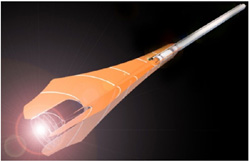
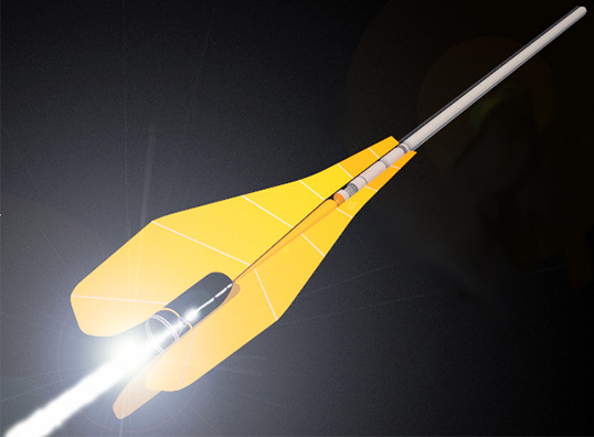
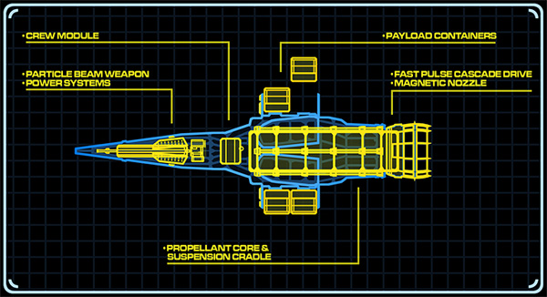
Icarus Interstellar has a project to design a fusion-rocket based interstellar spacecraft. They call it "Firefly". The technical lead director is Robert Freeland.
This is not a feeble design for a Mars mission, this is an interstellar starship with a whopping delta V of 10% the speed of light. The important thing to notice is the blasted thing is half a kilometer long, and emits torrents of deadly radiation in all directions like a global thermonuclear war.
Most of the other Icarus fusion designs use inertial confinement fusion. That's because IC fusion is easier to get halfway worthwhile power levels. Magnetic confinement fusion would be nicer but once you get enough nuclear fusion going to to be worthwhile, the magnetic bubble pops like a cheap balloon.
The drawback to IC fusion is that the confinement time is pathetic. The longer you confine the fusion reaction, the more of the fusion fuel actually burns and generates energy. But in IC fusion the first bit of fusion acts to blast the pellet apart, scattering the un-burnt fuel to the four winds.
Back in the olden days of fusion research, the darling was Z-Pinch fusion. You send a bolt of electricity (about 5 mega-amps) down the center of a long tube full of ionized plasma, creating magnetic field which compresses the plasma enough to ignite nuclear fusion. One of the big advantages with Z-Pinch was that the confinement time (and net energy output from the burn) can be increased by simply making the reaction chamber longer.
Unfortunately, the disadvantage is that Z-Pinch fusion suffers from several hydrodynamic instabilities which disrupt the plasma. So researchers stopped working on it in.
But in 1998 Dr. Uri Shumlak discovered you could eliminate the instabilities if you made the plasma move at high velocities. Based on this work, Z-Pinch was selected for the Icarus design.
The Firefly's long thin tail is the Z-Pinch tube, frantically fusing and radiating x-rays like a supernova. So the starship was given its name for similar reasons as the one on the TV show: it is a flying thing whose tail lights up.
The spacecraft profile is long and skinny, for two reasons:
Its cruise velocity is a substantial fraction of the speed of light (4.5c for the 2013 version). This make interstellar dust grains impact with about 9.1×10⁻⁴ joules worth of damage, the equivalent of 46,000 cosmic ray photons. You want to reduce the ship's cross section as much as possible to minimize the number of grain impact events.
The longer the ship is, the farther the payload can be placed from the deadly radioactive Z-Pinch drive, taking advantage of distance shielding.
Many other starship designs use 3He-D fusion, because all the reaction products are charged particles that can be easily shieldied. The drawback is that 3He is rare, you'd have to harvest the atmosphere of Jupiter for twenty years in order to get enough.
Instead, Firefly uses D-D fusion, since deuterium can be easily found in common seawater. Of course then you have to deal with all the nasty neutrons and x-rays produced by that reaction. Firefly's approach is to forgo the use of massive radiation shields, and instead try to let as much of the radiation escape into space. The Z-Pinch core is almost totally open to space with only a triad of support rails connecting the aft electrode and magnetic nozzle to the rest of the vessel.
Even with that, the waste heat is going to be titanic. That's where the heat radiators come in. Notice how they are the bulk of the ship. Makes the thing look like a garantuan lawn-dart. The radiators use beryllium phase-change technology, and are positioned as close as possible to the heat loads on the tail.
A long conical shield forwards of the reactor core deflects x-rays away from the payload using shallow-angle effects. The electrodes, rails, and other structure near the core are constructed of zirconium carbide (which is capable of surviving the intensely radioactive environment.
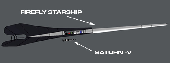
The 2014 design had a total length of just under one kilometer, half of which is the fuel tanks. The forward part of the ship uses the old fuel tank in lieu of spine trick in an effort to save on ship mass.
A fission reactor provides secondary power.
Firefly Starship, 2013 design
Firefly Starship, 2013 design
Firefly Starship, 2014 design
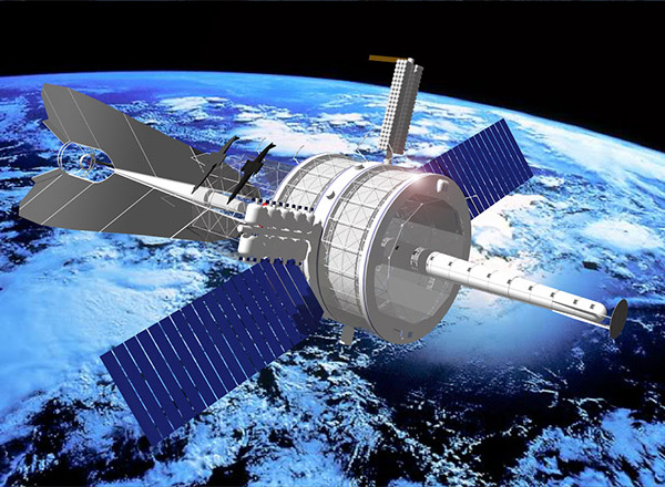
Firefly Starship being constructed in orbital drydock. Artwork by Michel Lamontagne? of Icarus Interstellar
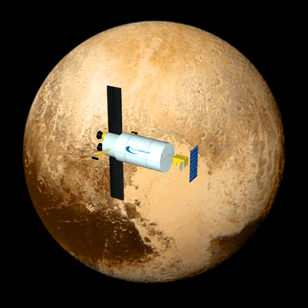
The blasted thing can deliver a metric ton of payload to Pluto in 3.75 years flat, instead of New Horizon's pathetic 30 kilograms taking nine years.
By "payload" the report means "everything except the engine and the fuel/propellant".
The engine a Direct Fusion Drive engine. This is not only a great rocket engine, it also can act as power plant. Which means when it gets to Pluto orbit, it can give the instruments a gigantic two megawatts of power, instead of the miserly handful of kilowatts most space probes have to make do with.
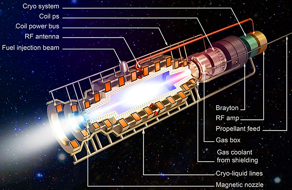
A pure fusion engine just uses the fusion reaction products as the reaction mass. This gives an impressive exhaust velocity of 25,000,000 m/s (Isp of 2,60,000 seconds). Unfortunately the propellant mass flow is so low that the thrust is negligible. So the engine shifts gears. A fusion afterburner is used, injecting cold propellant into the fusion reaction in what the reports calls a Scrape-Off-Layer (SOL). The exhaust velocity is drastically lowered to 100,000 m/s (Isp of 10,200 seconds) but the thrust jumps to a whopping 2.5 to 5 Newtons per megawatt of fusion power.
Reducting the exhaust velocity to 100,000 m/s sounds like a high price to pay, but that still makes a chemical or nuclear fission engine look like a couch potato.
With 1 megawatt power input, as the specific impulse varies from 8,600 to 9,200 seconds the thrust varies from 8 to 9.5 Newtons. Depending upon the propellant mass flow click for larger image
With 4 megawatt power input, as the specific impulse varies from 1×10⁴ to 1.2×10⁴ seconds the thrust varies from 35 to about 43 Newtons. Depending upon the propellant mass flow click for larger image
Given input power and propellant mass flow, color indicates thrust click for larger image
Given input power and propellant mass flow, color indicates exhaust velocity / specific impulse
Remember exhaust velocity in km/sec, divided by 9.81 gives the specific impulse in kilo-seconds click for larger image
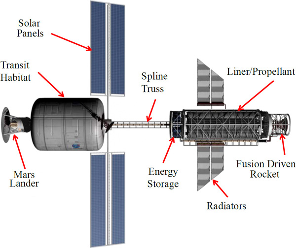
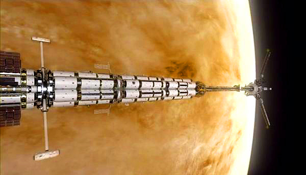
Spacecraft
Solar shield has been removed from image on the right in order to display the cryogenic tanks.
Radiator heat rejection is 840 kW, or 201 kW per side of each of the two radiator wings. Total radiator area is 50 m2. At an areal mass of 2.75 kg/m2, this is a total radiator mass of 133.5 kg.
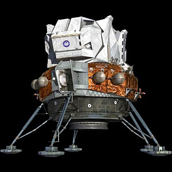
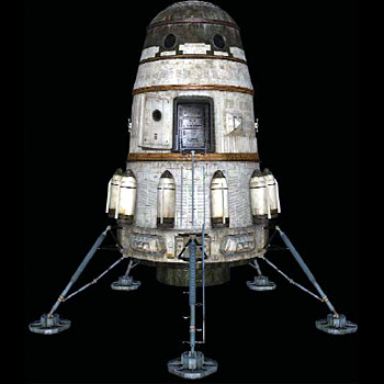
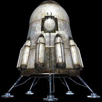
Lander
Solar array is 4 square meters producing 30 to 50 kilowatts. It is fed by a 1080 nm near-infrared laser beam from the orbiter, since the orbiter has two megawatts of power to waste. Solar panels rotate to track the laser beam during orbiter overflights.
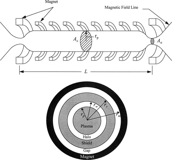
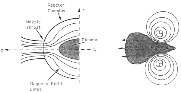
Gasdynamic Mirror
There are problems with attempting to confine ionized plasma in a reaction chamber long enough for most of it to undergo nuclear fusion. Either by trying to hold the frantically radiating piece of star-stuff in an impossibly strong magnetic chamber or by bending the chamber into a ring and letting the fusion stuff run around like stock cars on a racetrack. The fusion plasma fights you at every turn.
In the Gasdynamic Mirror propulsion system, they attempt to avoid that by making the reaction chamber a long and skinny tube, so the plasma just travels in a straight line until it is all burnt. The trouble is that the tube has to be really long. High exhaust velocity, remember?
Gasdynamic Fusion Propulsion System for Space Exploration by Terry Kammash and Myoung-Jae Lee (1995) has this useful table:
Sensitivity of Rocket Performance to Total Mass
System 1
System 2
Parameter
R = 50
R = 100
R = 50
R = 100
Rocket Length (m)
31.75
15.87
213
107
Plasma density (cm-3)
1×10¹⁶
2×10¹⁵
Plasma temperature (keV)
15
10
Magnetic field (T)
11.28
4.12
Thrust (N)
2.52×10⁴
3.36×10³
Total mass (Mg)
1,611
1,589
400
295
Specific impulse (s)
1.58×10⁵
1.29×10⁵
Specific power (kW/kg)
24
11
11
14
τRT to Mars (days)
106
105
143
124
Mg: mega-grams, another name for tonne or metric ton R: plasma mirror ratio τRT: round-trip travel time
Physics Basis For The Gasdynamic Mirror (GDM) Fusion Rocket by T. Kammash and W. Emrich Jr. (1998) had a sample spacecraft:
GDM Propulsion Characteristics
Fuel
50-50 detuterium-tritium
Specific impulse (s)
1.27×10⁵
Exhaust velocity (m/s)
1.25×10⁶
Specific power (kW/kg)
13.4
Thrust (N)
2.5×10³
Thrust power (MW)
2.2×10³
Payload + structural mass (Mg)
279.7
Engine mass (Mg)
101
Dry mass (Mg)
380.7
Wet mass (Mg)
423
Propellant mass (Mg)
42.3
Mass ratio
< 1.1
ΔV (m/s)
119,000
Initial acceleration (m/s2)
0.0059
Mars round trip (days)
170
β
0.95
R
100
Fuel density (cm-3)
1016
Temperature (keV)
10
Plasma length ~spacecraft length (m)
44
Plasma radius (cm)
5
Mg: mega-grams, another name for tonne or metric ton β: ratio of plasma pressure to vacuum magnetic field pressure (how efficient the magnetic field is in confining the plasma so it doesn't leak everywhere) R: plasma mirror ratio
When Kammash and Emrich calculated round trip mission time to Mars they used a simplistic Brachistochrone trajectory(accel to midpoint - flip - decel to destination), ignoring planet orbital motion and gravity. They chose what they considered to be appropriate values for the efficiencies and masses of the various components to obtain the engine and wet mass, but did not give a detailed breakdown in the report.
Propellant mass was a jaw-dropping less than 10% of wet mass (mass-ratio less than 1.1). Predictably the initial acceleration is a meager 0.0059 m/s2(about 0.74 snail-accelerations), but what did you expect, a torchship?
Performance Optimization of the Gasdynamic Mirror Propulsion System by T. Kammash and W. Emrich Jr. (1999) had a sample spacecraft (thrust, specific power, and spacecraft length are all about double the above design, wet mass is about triple):
GDM Reference Conditions
Fuel
50-50 detuterium-tritium
Specific impulse (s)
1.422×10⁵
Exhaust velocity (m/s)
1.395×10⁶
Specific power (kW/kg)
133
Thrust (N)
2.21×10⁴
Thrust power (MW)
1.189×10⁴
Dry mass (Mg)
1,500
Plasma length ~spacecraft length (m)
72
Plasma diameter (cm)
8
Vacuum β
0.95
Plasma density (ion/cm3)
2.2×10¹⁶
Plasma temperature (keV)
10
Gain factor (Q)
2.35
Magnetic field at center (tesla)
13.8
Magnetic field at mirror (tesla)
15
Fusion power (MW)
1.486×10⁴
Injector power (MW)
5,064
Bremsstrahlung power (MW)
317
Synchrotron power (MW)
103
Neutron power (MW)
1.189×10⁴
Neutron wall load (MW/m2)
187
GDM Vehicle Weights (Mg)
Magnets
30
Radiator
1,077
Thermal Electric Converter
55
Direct Electric Converter
53
Neutral Beam Injector
23
Fuel Cell/Capacitor System
35
Tritium Breeding System
10
Lithium Shield
37
Magnet Cooling System
19
Structure
36
Habitat
65
Mars Lander
60
Total Dry Mass
1,500
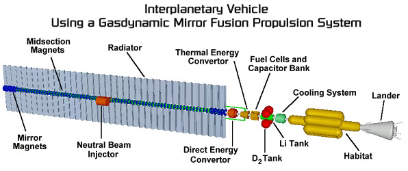
The fusion plasma is fueled and heated by neutral beam injectors. The injectors are powered from the nuclear fusion via a combination of direct (harvesting charged particles) and thermal (harvesting thermal gradients) energy converters. The direct electric conversion system has an assumed efficiency of 90%, the Brayton cycle thermal electric conversion system has an assumed efficiency of 30%, and the neutral beam injectors have an efficiency of 100%.
The charged particles from the fusion plasma will be split evenly between thrust and direct electric conversion.
The energy required to jump-start the engine will come from a capacitor bank charged by a set of fuel cells. The bank produces a 1,000 MW-sec pulse of electricity to start the fusion reaction. The capacitors have a charge storage density of 36 kJ/kg.
The fuel cells also provide station keeping power whien the fusion engine is shut down. When the fusion engine is started, some power is tapped to recharge the fuel cells.
The fusion engine has a radiation shield composed of liquid lithium. This is also part of the tritium breeder system.
The habitat module is a set of eight modified International Space Station modules, sized to proved long term accommodations for a crew of six. Storm cellar is a room with walls lined with foodstuffs, water, and waste products. The life support system is not fully closed, oxygen/carbon dioxide cycles are closed but foodstuffs are considered to be consumables.
Power budget for habitat module is 100 kW, which is a pitance compared to the megawatts demanded by the fusion engine. When the engine is shut down the 100 kW comes from the fuel cells.
The lander is a resuable launch vehicle having a vertical takeoff, vertical landing design. It includes a small in-situ fuel processing system powered by a nuclear reactor. Perhaps something like Zubrin's NIMF.
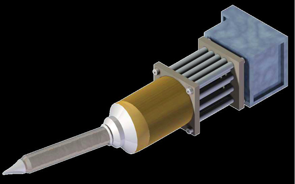
MIF cleverly avoids the problem of trying to squeeze a blob of fusion fuel using a rubbery immaterial magnetic field. It has a foil ring of lithium, uses the magnetic field to squeeze the foil, and the hard very-much-material foil mercilessly squeezes the fusion fuel to fusion densities.
The main draw-back is electromagnetic coil has to be savagely pulsed with a high current. This makes for lots of wear-and-tear on the coil, the energy storage requirements are (heh) astronomical, and you need massive switches to control the pulses without vaporizing.
The researchers liked the foil squeezer concept in the abstract, but there had to be a better way to squeeze it.
They thought outside the box and turned the problem on its head. If you had a powerful constant non-pulsed electromagnetic coil, all the draw-backs go away. The only problem is that if you have a blob of fusion fuel surrounded by some lithium foil, moving at a leisurely rate into the magnetic field, the foil will not be squeezed fast enough to ignite fusion.
Oh, so the problem is speed? Then the solution is easy. You fire that little foil-wrapped fusion nugget through the constant magnetic field at about ten kilometers per second. That will make the crush rate fast enough to ignite fusion. 10 km/sec sounds really fast (and it is) but the final fusion created exhaust will be more like 300 km/sec, so it is worth it.
Actually, from the frame of reference of the fusion nugget, there is no difference between a pulsed magnetic field acting on a stationary nugget and a constant magnetic field acting on a rapidly moving nugget which is entering the field.
From an engineering standpoint, you are transferring the engineering challenge from the electromagnetic coil design to the fusion nugget gun design. The difference is that the nugget gun is a heck of a lot easier to design and build. The coil has to pulse all its power in a matter of microseconds, but the gun can take its sweet time accelerating the fusion nugget if you make the gun long enough.
The nugget gun ("target accelerator") fires the fusion nugget ("fuel target", the blob of fusion fuel wrapped in lithium foil) at high velocity toward the hole in the electromagnetic coil. The high velocity and strength of the magnetic field rapidly puts the squeeze on the fuel target, which promptly explodes into thermonuclear fusion. The reaction products and lithium plasma then exits out the magnetic nozzle, producing thrust with an rapid exhaust velocity that makes chemical exhaust look like a drugged snail.
As with the original MIF drive, the fusion fuel is the "fuel" while the foil is the "propellant". Lithium or Beryllium can be used to "shift gears." Lithium gives a higher specfic impulse but lower thrust, while Beryllium is the opposite. They looked at using Aluminum, but it performed rather poorly.
The researchers looked at several options for the target accelerator:
Light Gas Guns: can accelerate target to a few km/sec. Not good enough for actual use, maybe for ground tests.
Rail Guns: the rails erode so badly that they would would have to be replace after a few shots. Not good if you are firing targets at a rate of 10 Hz or so. The rails would have to be replaced every quarter of a second. Can accelerate target to a few km/sec. Not good enough for actual use, maybe for ground tests.
Laser Ablation Accelerator: can accelerate the target to several tens of km/sec. And as an added bonus the laser can be used to preheat the target.
The researchers calculated that to get a nugget coated with an Aluminum foil liner with a one square centimeter cross-section up to 10 km/sec will require:
10 kilowatt laser: ablates 15% of the Aluminum liner mass for 10 km/sec
100 kilowatt laser: ablates 5% of the Aluminum liner mass for 10 km/sec
1,000 kilowatt (1 MW): ablates 1.5% of the Aluminum liner mass for 10 km/sec
Yes, I know they are not going to use Aluminum, I guess they had the data easily at hand. Lithium and Beryllium
After examining the useful fusion fuels, the researchers decided to go with good ol' Deuterium-Tritium. It is the easiest to ignite, a pity about all those nasty neutrons generated by the reaction.
The researchers looked at a range of missions
Payload 20,000 kg: crew vehicle for fast transport
Payload 50,000 kg:
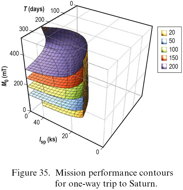
Payload 200,000 kg: cargo mission supporting an extended presence at Mars or Saturn
Figure that an Orion Multi-Purpose Crew Vehicle has a mass of 25,848 kg. A standard TransHab has a mass of 34,050 kilograms, but can be downsized to 50,000 - 25,848 = 24,152 kilograms. That would fit the report's standard payload of 50,000 kg.
SCALING
Propellant tank mass is equal to 0.1 × propellant mass.
Total thermal system mass is complicated, because it is so sensitive to system efficiency. They assume a rejection temperature of 1,250 K.
Pjet = ½ × F × g0 × Isp
where
Pjet: power in the exhaust jet F: Thrust (7,800 N) g0: Terra Gravity (9.81 m/s2) Isp: Specific Impulse (32,200 sec)
Plugging in the values for the Lithium foil liner, Pjet = 1,231,939,800 W or 1.2 gigawatts.
Pjet = Pgen - Pgen×φtherm - Pgen×(1-φtherm)×φloss
where
Pjet: power in the exhaust jet Pgen: power generated by the fusion reaction φtherm: fraction of the fusion reaction power which becomes thermal losses in the coils and structure φloss: fraction of remaining power lost to space
Assuming φtherm=0.1 and φloss=0.1 the equation reduces to:
Pjet = 0.81×Pgen
q = 0.19×Pgen
Assuming that the power generated by the fusion reaction is 1.2 gigawatts, this means the waste heat q is 0.2 GW.
A = q / (ε × σ × T4)
where
A: radiator surface area q: waste heat to heat radiator to handle (0.2 GW) ε: emissivity in infrared (optimistically set to 1.0) σ: Stefan–Boltzmann constant (5.670373×10⁻⁸ W·m−2·K−4) T: temperature (heat rejection temperatore of 1,250 K)
Doing the math means that the radiator surface area A is 1,360 m2. They figure the double sided radiators have a density of 5 kg/m2, so the radiators proper will have a mass of 6,800 kg. The pump/cryo has the same mass of 6,800 kg.
So the total thermal system mass is 13,600 kilograms.
Propulsion System Mass is Pjet / 17.6, where Pjet is in kilowatts. So if it is 1.2 GW, it is 1,200,000 kW. The report later thinks that 17.6 is optimistic, and thinks it is closer to 15.9.
Structural Mass is 0.1 × Inert Mass, which is the common standard estimate for in-space, medium-thrust vehicles.
Avionics Mass is 0.02 × Inert Mass, which is the common standard estimate for in-space, medium-thrust vehicles.
Mass Growth Allowance is 0.5 times Inert Mass, though the report later figures 0.5 is pessimistic and thinks it is closer to 0.33.
Graph shows the performance for a trip to Mars.
Looking at the start points of the curves, you can see the Beryllium (Be) liners (propellant) are theoretically capable of somewhat shorter trip-times than the Lithium (Li) liners. But the cost is the required propellant mass goes up rather steeply click for larger image
There are 36 living modules composing the centrifuge ring. Each module is 4 meters in diameter and 7.3 meters long. The hull is an aluminum-lithium alloy 4 centimeters thick to shield from galactic cosmic radiation. So at a rough guess there is about 3,300 cubic meters of pressurized habitable volume.
Module types include airlocks, bathrooms, bedrooms, cafeteria, controls, library, life support, recreation, recycling, research, saferoom (storm cellar in case of solar proton storms I guess), and storage.
There is a pressure-tight spacedoor between each module. It is a damage control device to allow isolating a module in case of hull rupture/depressurization, toxic gases, or fire. Doors will handle 14.6 psi of pressure, low temperature, and will close automatically. To reduce mass each door is a sandwich of an aluminum honeycomb 13.5 cm thick between two sheets of titanium each 0.25 cm thick. The door is 187 cm high by 93.1 cm wide with a total mass of 10.7 kg. Corners are rounded to prevent curling and to press equal force around edge of seal. Doors are on tracks and can be opened/closed by spring, electric motor, or manually. If there is a pressure difference the door cannot be opened. Assuming a minimum 55 kPa atmospheric pressure to prevent suffocation, and a hull puncture the size of an entire door (1.67 m2), the doors have to shut within 0.03 second to keep the two living modules adjacent to the breached modules above 55 kPa, and within 1.14 second to keep the entire habitat ring above 55 kPa.
Not shown is any sort of a landing craft, which presumably would be parked on the ring hub, nose-to-nose. Without a lander, the entire trip is kind of pointless.
The modules are on the rim of a centrifuge 80 meters in diameter rotating at 4.2 rpm to provide an artificial gravity of 0.8g. This provide enough gravity to reduce bone decalcification, and is below the 6 rpm spin nausea limit. This puts the modules under a shear stress of 22 MPa, which the aluminum-lithium allow can easily handle.
The centrifuge ring is supported by four radial supports. Each is 38 meters long, with an out side diameter of 4 meters with a 13.2 centimeter thickness.
As with all centrifuges, astronauts and other objects moving around will unbalance the centrifuge and make it unstable. The four centrifuge radial support arms have movable masses ("mass elevators") which dynamically ensure the centrifuge center of mass stays positioned on the centrifuge center of rotation. Assuming a maximum imbalance of 52.5% to 47.5%, and a radial arm length of 40 meters, each movable mass will need to be 481,000 kilograms. They will be made of cast iron, cylindrical with a radius of 1.8 meters and a length of 6.15 meters. To avoid problems with coriolis acceleration, the movable masses should have a velocity of no higher than 0.1 m/s when they are moving to correct an imbalance.
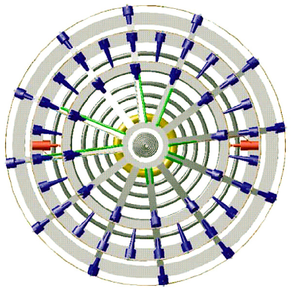
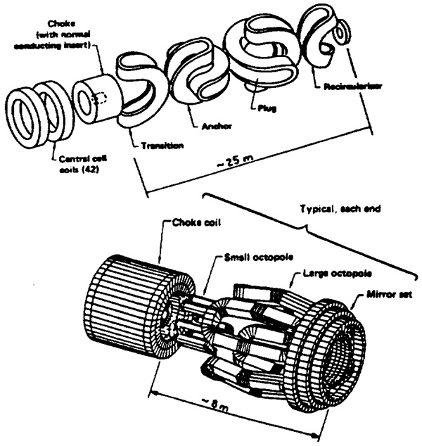
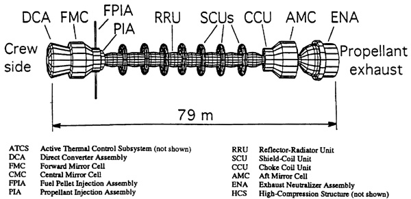
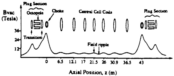
The tandem mirror fusion reactor is composed of 25 magnetic mirror cells. Each cell has 4 belt radiators for removing waste heat. There are 100 belt radiators total.
The specific power is 833 kg/MWthrust, which is about an order of magnitude worse than the later 3He-D Mirror Cell design (64 kg/MWthrust)
Maximum radiation dosage from the fusion reactor that the astronauts can be safely exposed to was set at 2.5 millirem per hour (0.025 millisievert/hr).
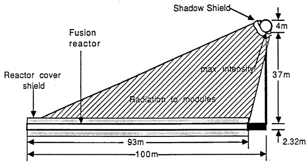
A shadow shield is set adjacent to the living modules. The shield is a ring-shaped steel tank full of boric acid. The shadow shield is 1.75 meters thick along the line of radiation flux, and has a total mass of 3,890,000 kilograms. The tank walls are 5 centimeters thick, so about 5% of the total shield mass is steel tank.
Alternatively the shadow shield can be placed so it encases the long reactor cylinder (a "reactor cover shield"). This would be lighter, but now the shadow shield has to cope with the intense waste heat from the reactor. The shield would be 1.37 meters thick and have a lower mass of 1,970,000 kilograms, plus the mass of the cooling system.
One calculation predicted a Terra-Mars trip would take 178 days at an acceleration of 1.6×10⁻⁴g and a payload fraction of 0.40. But when I look at the report's reference for that statement, I discover that they are quoting a 1964 book by Ernst Stuhlinger (the designer of the Mars Umbrella Ship) called Ion Propulsion for Space Flight. In other words the report writers did not actually calculate the performance parameters of the Tandem Mirror fusion reactor.
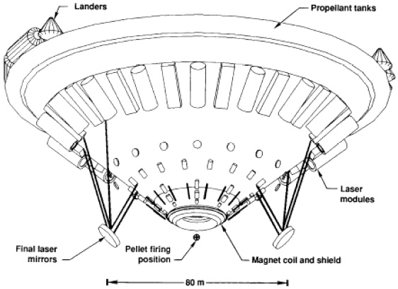
This is from A Laser-Fusion Rocket for Interplanetary Propulsion by Roderick A. Hyde (1983). I apologize for any mistakes but the document appears to be scanned from a poor photocopy of a pre-print that was almost unreadable. As you can see from the diagrams below.
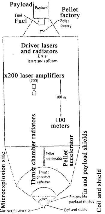
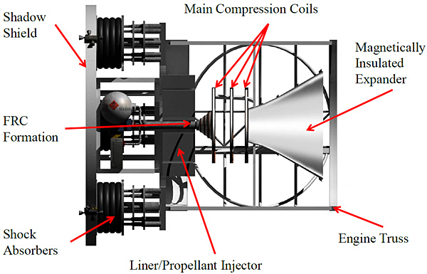
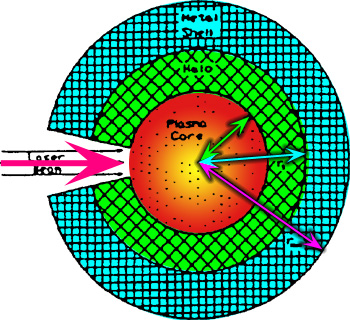
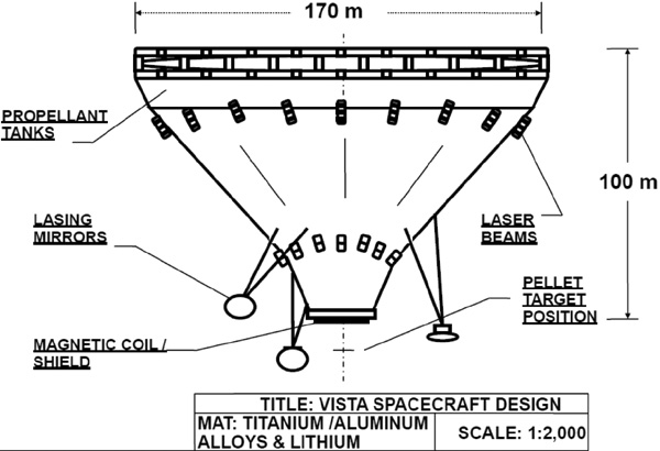
Pellets of fusion fuel (with a coating of propellant) are injected into the reaction point at a rate of 100 pellets per second. There they are imploded by the Driver using a 2 megajoule? pulse of laser radiation from a krypton fluoride laser (which is only 6% efficient). The laser pulse is divided into 8 laser beams which are reflected by mirrors to converge at the reaction point from all directions. The laser pulse compresses the pellet, igniting the fusion reaction. Two krypton fluoride lasers will be used at 50 Hz, alternating pulses to make an effective pulse rate of 100 Hz. The Magnetic nozzle directs as much as it can of the exploding pellet's plasma energy into producing rocket thrust, and prevents as much as it can of the plasma energy from frying engine components.
Dr. Hyde estimates that this engine can carry 1,500 metric tons of payload, with an average trip-time of 6 weeks to Mars, 3 months to Jupiter, and 1 year to Pluto.
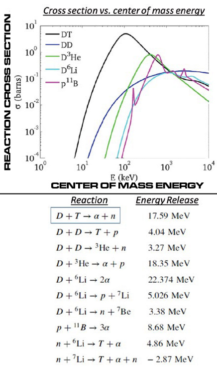
Pellets
For the fusion fuel inside the pellet, you want as much of the energy to be in hot plasma as possible. Any neutrons and x-rays produced are wasted energy, since they contribute nothing to the thrust and cause damage to the ship and crew. The report has a long section discussion the relative merits of various fusion fuels, but Dr. Hyde settles on Deuterium-Deuterium fusion. The pellets contain 15 milligrams of deuterium salted with 36 micromoles of tritium.
About 30% to 50% of the deuterium fuel will burn, the rest will be wasted. Deuterium has a specific energy of 345 megajoules per milligram. The engine is designed for 2000 megajoules per pulse, so for deuterium at 40% burnup each pellet will require 15 milligrams of deuterium. The pellet of deuterium will be coated with propellant to increase thrust (increasing the propellant mass flow mdot) so that the total pellet mass is 150 milligrams. Pretty much any element can be used for propellant, Dr. Hyde used spare deuterium. This means that by varying the amount of extra propellant the engine can shift gears, i.e., trade exhaust velocity for thrust and vice versa. The on-board pellet factory can change this on the fly.
1280 megajoules will be in the form of charged particle fusion energy for thrust, about 710 megajoules will be wasted in the form of x-ray and neutron radiation (330 MJ of x-rays, 380 MJ of neutrons).
Magnetic Nozzle
The primary task of the thrust chamber's magnetic nozzle is to convert the exploding plasma into thrust. The secondary task is to generate the power required to energize the lasers in the driver. The tertiary task is to breed tritium for the fusion pellets, since the blasted stuff has an unstable half-life of barely 12 years.
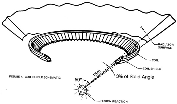
A superconducting coil creates a magnetic field that reflects the exploding plasma. The coil is encased in neutron radiation shields, and has a heat radiator to keep the radiation shields from melting. The radiators are on the part of the coil farthest from the ignition point.
In a latter design described in a document I have as yet failed to lay my hands on, there are two coils instead of one: the S-coil and the B-coil. The S-coil is above the ignition point and the B-coil is below. The S-coil is smaller with a denser magnetic field, to encourage the plasma blast to exit out the weaker B-coil. The coils resemble slices of a cone
Since there is not much that can be done to stop the harmful x-rays and neutrons, the idea is to make the magnetic nozzle as "transparent" as possible. It is an open framework where all the components occupy a small fraction of the solid angle as seen from the fusion pellet explosion (just see the diagram below). You want to make all the components "edge on" to the explosion, which is why the coils look like conic sections. In other words, they are blade shields.
As the exploding plasma expands against the magnetic field of the thrust chamber, the field is moved. Induction coils (next to the nozzle coils) harvest this motion to generate electricity for the driver. 33 megajoules of electricity is generated, and stored in a compulsator flywheel for the laser driver to use for the next laser pulse.
Other engine designs try to turn all the plasma into electricity and use that to run an ion drive or something. This adds penalty mass in the form of the generator, and reduces the power available by the inefficiency of the generator. Dr. Hyde thinks it is better to just use the plasma directly as thrust.
The tritium breeder has to produce a minimum of 36 micromoles of tritium per pellet explosion. Otherwise the tritium supply will be operating at a loss, and will eventually run out. This is done with a tube full of liquid lithium-6 and lithium-7 with a loop near the detonation point. The lithium converts the neutrons from each blast into tritium. The trouble is that with the design of the lithium blanket there was a pathetic breeding ratio of only 54%, which mandates a neutron interception fraction of 0.055 in order to make 36 micromoles of tritium. The bottom line is that the liquid lithium will be heated at a hideous rate of 4.2 gigawatts, needing a huge heat radiator to prevent the rocket from vaporizing.
This means that the tritium breeding places a floor on vehicle heating; pellets should have a little tritium as possible. Dr. Hyde set it at 36 micromoles for reasons too complicated for me to understand.
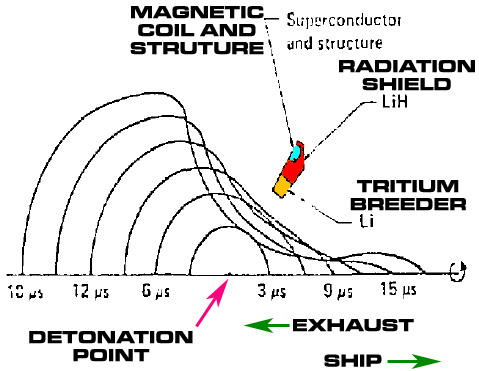
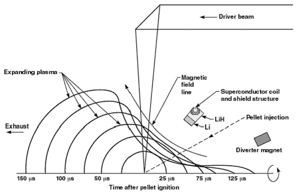
Cross section view of the magnetic nozzle along the thrust axis. The curved lines are the outline of the plasma explosion at microsecond (μs) intervals after detonation. As you can see most of the plasma is traveling in the proper direction for exhaust. You can also see the small naughty jet of plasma trying to travel up the thrust axis to hit the ship in the rear.
The lithium (Li) loop tritium breeder is placed on the inner side of the magnetic nozzle coils, so they can soak up the neutrons and partially shield the coils. The loop and the coil are wrapped by a blade-shaped metal skin, which acts as an eddy current shield.
The magnetic nozzle is a high-energy type, unlike the low energy nozzle on a Daedalus starship. This means the magnetic field contains about five times the energy of the exploding pellet (radius of 6.5 meters with a current of 22 MA), where the Daedalus magnetic field is weaker than the pellet. High-energy types are more efficient at converting pellet explosion energy into thrust.
This is an axially-symmetric nozzle which means a jet of hot plasma will escape along the long axis, i.e., right into the ship's backside. A smaller magnet is used to deflect this jet so it misses the ship's derrière
The magnetic nozzle is 65% efficient at converting the exploding plasma into thrust. Coupled with the 1280 megajoules of plasma energy per pellet detonation means that the entire engine converts about 42% of the total pellet energy into thrust.
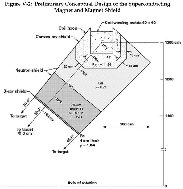
The coil will have to be a superconductor, if for no other reason because 22 MA of current will vaporize a conventional coil. Dr. Hyde specified a vanadium-gallium (V3Ga) superconductor with a 15.8 Tesla peak coil field at 4.8 K temperature will have a current density of 270 kA cm-2. The coil will be embedded in a matrix of vanadium and aluminum. The coil and matrix will have a radius of 6.5 meters and a mass of 8.7 metric tons.
However, remember that the same charge of magnetic field repel each other. 15.8 freaking Teslas will be doing their darnedest to expand the coil (read: make the coil violently explode in all directions). The technical term is "magnetic bursting force." This will be resisted by 8.5 metric tons of structural composite. So the total coil+structure mass is 17.2 metric tons.
Keeping the coil cooled down to 4.8 K when it is being exposed to 2 gigawatts of neutron and x-ray energy is somewhat of a challenge. The lithium loop will remove the heat created by neutron radiation in addition to breeding tritium. Dr. Hyde figures it can handle the 2000 watt heat load.
Even worse, some of the neutrons that enter the coil's lithium hydride (LiH) radiation shield will scatter right back out, thus they can hit the coil from its unprotected rear side. The radiation shield will have to cover one side of the coil that is not in direct line of sight of the detonation point (the side where radiation can be reflected off the payload's radiation shield right back at the coil).
And then there is x-rays and gamma-rays, requiring a lead coating on the radiation shield.
So the lithium loop will require an 8.1 metric ton refrigerator to reject the heat plus 10 tons of liquid lithium, the lithium hydride neutron radiation shield is about 44.4 metric tons, and the gamma-ray radiation shield is about 56.3 metric tons.
Total magnetic nozzle mass: 126 metric tons.
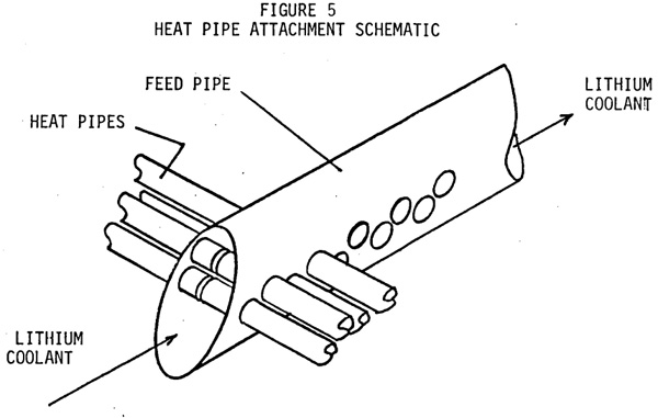
As previously mentioned the magnetic nozzle system has to cope with 4.2 gigawatts of waste heat, from x-rays hitting the lead shield and neutrons hitting the lithium loop. The lithium will be the thermal working fluid to move the heat to the heat radiators (then it will have its tritium harvested). It will be pumped by a 20 megawatt MHD pump utilizing the thrust chamber's magnetic field. At a given time there is 10 metric tons of liquid lithium inside the thrust chamber sopping up neutrons, but the total system has 27 metric tons. This includes the liquid lithium in the long pipes leading to the heat radiators, and inside the radiators themselves.
The heat radiators are an array of 7,800 heat pipes, each 11 meters long and using lithium at 1500 K. The array mass is 40 metric tons.
Driver system
Laser amplifier. The driver needs 200 of these.
The pellets are imploded by 2 megajoules worth of laser beam applied in 10 nanoseconds. Dr. Hyde considered electron beams, but they are hard to focus on a tiny pellet and also cause nasty bremsstrahlung radiation. Proton beams have no bremsstrahlung, but since the detonation point is going to be ten to twenty meters away the proton beam will bloom due to electrostatic repulsion and be impossible to focus on the pellet.
Due to problems with heat rejection speed, Dr. Hyde decided to go with two laser systems alternatively firing at 50 Hz instead of one laser system firing at 100 Hz.
Each system will require 100 laser amplifiers (see diagram above). Each amplifier has a rotating cylinder with its lasers and a non-rotating heat pipe radiator. There are five lasers in the cylinder, firing at a rate of 10 Hz. Actually the cylinder is more like gas filled tube with five laser "buckets" on the rim. Between pulses the hot laser gas is exchanged with cool gas in the core, and the heat is rejected by liquid sodium heat pipes. The heat pipes radiate at a temperature of 900 K.
A module has a mass of 955 kilograms, of which 520 kilograms is laser and 435 kilograms is heat radiator. 100 modules per laser system and 2 laser systems means 200 modules are needed. Total mass is 191 metric tons.
In addition, the laser systems will need 12 metric tons of connecting trusses, 6 metric tons of optical system to combine and plus-stack the beams, and 11 metric tons for the oscillator system.
The laser driver will require 33 megajoules of energy per pulse. As described above, energy will be harvested from the engine and stored in a compulsator. 33 MJ will be extracted from the compulsator and placed in a capacitor bank, much like a camera strobe.
The power transmission lines connecting the engine and the compulsator have a mass of 5 metric tons, the compulsator has a mass of 12 metric tons, and the capacitor banks mass 25 metric tons.
Miscellaneous Components
There will be an neutron+gamma ray radiation shadow shield located 20 meters from the detonation point to protect the payload region. It will subtend a 3° half-angle, plus thin fins to shadow the thrust chamber heat radiators. Unfortunately the magnetic nozzle coil will scatter some radiation over the edge of the shield. Right behind the shield will be a magnet to deflect the naughty plasma jet.
The fusion pellets have to travel from the rear of the shadow shield to the detonation point during inter-pulse time. This means they have to have a speed of 2 kilometers per second. They will be propelled by a magnetic accelerator or laser ablation. Extreme precision will be required. In practice a pellet might be deliberately delivered slightly off axis from the detonation point in order to do thrust vectoring.
Behind the payload region is the pellet factory. It will take deuterium, tritium from the tritium breeder, and propellant and manufacture them into pellets. Dr. Hyde did not bother designing this but said he doubted it would be massive.
For cargo missions, Dr. Hyde figures the spacecraft will require 650 metric tons of deuterium fuel. If the acceleration is always below 0.1 g then the mass of the fuel tank would be about 16 metric tons.
The engine will be off in between missions and during coasting, so the engine will generate no power. An auxiliary nuclear fission reactor will be provided for housekeeping power and to restart the propulsion system. A 1 megawatt reactor with a mass of 5 metric tons will do.
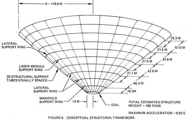
There will be a truss to transmit thrust from its origin at the magnetic nozzle coil up to the payload. It has a mass of 20 metric tons. It has 8 primary thrust-bearing members. As with the lithium pipes (heat transfer and tritium breeding) the thrust-bearing members will be shadowed by the magnetic nozzle coil shield until the members reach the inner edge of the thrust chamber radiator (50 meters from the detonation point). At that location the members are laterally tied together by a structural ring, then fan out towards the laser driver radiating array. Upon reaching this site, the truss no longer has circular symmetry but is instead biased towards the radiation plane of the rocket. The thrust bearing members are hollow pipes tied together by a lateral truss to avoid buckling. It is rated for a maximum of 5,000 kilonewtons thrust.
Vehicle Performance
The important performance numbers to look at are the ratio of maximum exhaust power to engine mass (power-to-mass ratio) and the exhaust velocity.
The main limit on the power-to-mass ratio is the heat rejection capacity of the laser driver and thrust heat radiators (if you run the engine at a higher rate than the radiators can cope with the ship will melt or vaporize). The secondary limit is the actual mass of the engine.
Exhaust velocity is limited to a maximum of about 2.6×10⁶ m/s due to the energy limits of deuterium fusion. In practice it will be further limited by the energy wasted producing neutron and gamma-rays, inefficiency of magnetic nozzle converting plasma energy into thrust, and most importantly the fraction of the pellet mass used to implode the fuel.
The engine is pretty lousy for interstellar propulsion at least 20% c due to the the exhaust velocity (20% c is greater than 2.6×10⁶ m/s so mass ratio will be ugly).
However the engine will be marvelous for interplanetary travel. In that role the main limit is the power-to-mass ratio. Given a good ratio, the engine can be optimized to increase the thrust a little bit at the expense of the exhaust velocity (shifting gears). As a general rule you want the thrust and wet mass of the spacecraft to be such that it can crank out a minimum of 5 milligees (0.05 m/s2) of acceleration. Otherwise the spacecraft will take years to change orbit. It is worth it to up the thrust enough to allow this even if you are robbing the exhaust velocity.
w = ƒτ * sqrt( (2 * Ek) / mp )
P = (mp * ν * w2) / 2
P = ν * Ek * ƒτ2
P = (F * w) / 2
αp = Pjet / Me
F = mp * ν * w
mDot = mp * ν
where:
w = exhaust velocity (m/s) {2,650,000 m/s} which elsewhere in this site is symbolize by Ve P = jet power, thrust power (W) {54,100,000,000 W = 54.1 GW} which elsewhere in this site is symbolize by Fp αp = power-to-mass ratio or specific power (W/kg) {110,000 W/kg = 110 kW/kg} F = thrust (N) {40,000 N} ƒτ = efficiency of magnetic nozzle in converting charged particle energy into jet energy {0.65} Ek = charged particle fusion energy (J) {1,280,000,000 J} mp = pellet mass (kg) {0.00015 kg} ν = pellet repetition rate (Hz) {100 Hz} Me = mass of engine (kg) {486,000 kg} mDot = propellant mass flow (kg/s) sqrt(x) = square root of x x2 = x squared
In the following tables, a "VIP Mission" is one with the shortest possible trip time, but with a microscopic payload. A "Cargo Mission" is one with a longer trip time in exchange for a reasonable cargo. In the cargo mission, given the total starting mass of the spacecraft (2,592 metric tons), 4/16ths is fuel/propellant mass (648 metric tons), 9/16th is payload mass (1,458 metric tons), and 3/16ths is engine mass (486 metric tons). The VIP mission has the same total starting mass and engine mass. The difference is that the payload mass is reduced and the fuel mass is increased.
Over a given mission the exhaust velocity and thrust is varied by changing the pellet mass.
Note that an acceleration of 1 g is 981 cm/s/s. 5 milligees is about 5 cm/s/s
VIP Missions Table 4
Parameter
Mars ♂
Jupiter ♃
Pluto ♇
Distance (AU)
0.6
5.2
39.5
Transit Time (dys)
9.4
39.8
153.9
Speed Max (km/s)
165
339
667
Acceleration Max (cm/s/s)
81.1
39.5
20.1
Exhaust Vel start (km/s)
51
104
205
Exhaust Vel end (km/s)
271
557
1,095
Pellet Mass start (gm)
422
100
26
Pellet Mass end (gm)
14.8
3.5
0.91
Cargo Missions Table 5
Parameter
Mars ♂
Jupiter ♃
Pluto ♇
Distance (AU)
0.6
5.2
39.5
Transit Time (dys)
22.2
93.6
362
Speed Max (km/s)
70
144
284
Acceleration Max (cm/s/s)
14.7
7.11
3.63
Exhaust Vel start (km/s)
281
577
1,135
Exhaust Vel end (km/s)
375
770
1,135
Pellet Mass start (gm)
13.8
3.3
0.85
Pellet Mass end (gm)
7.8
1.8
0.48
The tables above were calculated by with the following equations, whose implications I have not fully digested.
For interplanetary travel, the capability of an Inertial-confinement Fusion Rocket (IFR) is limited more by its power-to-mass ratio, than bi its exhaust velocity. The limitation on exhaust power translates into a bound on the product of exhaust speed "w" and acceleration "a", i.e., on aw. While a large value of w will eventually enable the rocket to reach a high speed, the low a means that doing so takes up a lot of time and distance. When the goal is to travel a given distance "D" as quickly as possible, the optimum technique involves accepting a lower w value in exchange for higher acceleration. This dialing of w can be accomplished in an IFR by placing excess propellant mass outside of the fusion pellet. The extra material lowers the exhaust velocity of the pelet, while increasing its impulse. Pellet-nozzle expansion calculations have been performed for different overall pellet masses, and shown no change in nozzle efficiency.
We have used three models, of increasing sophistication and opacity, to analyze the performance of this IFR. The first is the classic power-limited model, in which gravity and exhaust velocity limits are neglected. This case is easy to solve, and indicates the the pertinent scaling and operational modes. Next the w constraint is included. The resulting zero-gee motion can also be analytically solved, but in less useful form. This solution is then used as the starting point when numerically solving the 2D problem in which solar graviyt is included along with the w and aw constraints.
By neglecting solar gravity and vehicle exhaust velocity limits, we gain a simple insight into the performance capabilities of an IFR. Suppose one wishes to travel a distance "D" in time "T", starting and stopping at rest. The rocket has an initial mass of "M0", of which the powerplanet accounts for a fraction "β" and is characterized by a power-to-mass ratio of "η". The optimum tradeoff between a and w occurs for the time dependent acceleration:
The payload fraction "λ" can be shown to be given by
Note that D, T, and η appear only in the dimensionless parameter α. The trip time is seen to vary with the 2/3 power of distance, and with the inverse cube root of the power-to-mass ratio. There are two interesting operational modes suggested by Eq. 2. The "VIP" mode yields the shortest possible trip time, but a vanishing payload. For this mode:
For economical operation, one is willing to accept a longer trip time in exchange for a large payload fraction λ. The "Cargo" mode results from maximizing the payload throughput λ / T by optimizing over T and the choice of β. This optimum occurs at α = 1/16 and β = 3/16, resulting in a payload fraction λ = 9/16 and a fuel fraction of 1/4 (4/16). For this mode:
In Table 4 we demonstrate the VIP mode capabilities of this rocket, and show Cargo performance in Table 5. For purposes of comparison, the VIP mode numbers assume the same powerplant fraction, β = 3/16, which is optimal for cargo carrying; so the payload of the Cargo mission is swapped for more fuel in the VIP mission. The rocket exhaust power and exhaust velocity are given by:
(ed note: those two equations were already presented above)
For the current design, the nozzle efficiency ƒτ is 0.65, so the power P is 54.1 GW. Using the powerplant of Table 3, we find a power-to-mass of 110 W gm-1. The examples illustrated in Tables 4 and 5 span the range of solar system mission; Martian close approach to show high acceleration capability, Pluto transit to show the opposite extreme, and an average Jupiter mission. The Tables list the distance, trip time, maximum speed, maximum acceleration, the exhaust speed at the beginning and end, and the overall pellet mass at beginning and end.
The potential of this IFR for solar system propulsion is graphically illustrated by the trip times shown in Tables 4 and 5. A quick trip to Mars can be made in 9 days, while even in Cargo mode, Pluto can be reached in a year. In Cargo mode, the rocket can deliver 1,500 metric tons per mission; while the VIP method still permits delivery of ≈ 50 metric ton payloads.
While enlightening, the above analysis is incomplete. The acceleration profile of Eq. 1 requires a zero acceleration and infinite exhaust velocity at the midpoint of the trajectory. Hence, the exhaust speed constraint will be violated during these trajectories. This will certainly occur in the middle of the trips, and for longer missions can occur throughout the journey. When a limitation on w is imosed on the trajectory optimization problem, its solution is no longer as transparent as Eq. 2; but analytic results can still be derived.
This is apparently from a different but related study by Hyde. Note there are two coils instead of one. Note similarity to Luke Campbell's blade shields. Apparently from "Prospects for Rocket Propulsion with Laser Induced Fusion Microexplosions" by R. Hyde, L. Wood, and J. Nuckolls (1972)
Images from "Comparison of Fusion/Antiproton Propulsion Systems for Interplanetary Travel by Stanley K. Borowski (1987)
click for larger image
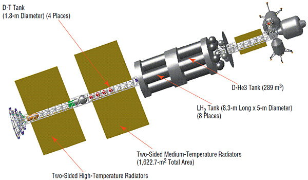
It is another proposal for the baseline Human Outer Planet Exploration (HOPE) mission. It delivers the standard HOPE payload using a spacecraft propelled by a Magnetized Target Fusion engine. The variantions are deuterium-deuterium (D-D) or deuterium-helium-3 (D-3He) propellant and with 30- or 180-day stay times on Callisto.
Detailed breakdown of vehicle mass, for all three option
click to see entire list
Vehicle Components:
x6 Liquid Hydrogen (LH2) tanks: propellant part of the fusion liner
x1 Deuterium tank: fusion fuel part of fusion liner
Reaction Control System (RCS) thrusters and propellant tanks: to change ship attitude and for artificial gravity
Heat Radiators: dual two-sided radiators, for high-temperature, medium-temperature, and crew/avionics heat rejection
SP-100 reactor: 300 kW fission reactor
x4 Deuterium-tritium tanks: for the fusion target
Water (H2O) tank: anti-radiation shadow shield protecting crew from engine radiation
Magnetized target fusion (MTF) engine: main propulsion
The vehicle uses the "tumbling pigeon" method of artificial gravity (rotates end-over-end). At the center of mass of the TransHab habitat module the artificial gravity is 0.25 g. It takes about 8,651 megajoules of energy to spin up or to halt spin.
Red deuterium-tritium tanks contain fuel for the fusion target.
Gray deuterium tank and LH2 hydrogen tanks contain gas for the plasma liner click for larger image
Note green superconducting magnetic energy storage (SMES) envelope below SP-100 nuclear reactor.
Note orange H2O tank acting as an anti-radiation shadow shield. click for larger image
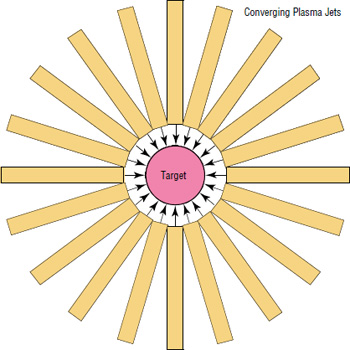
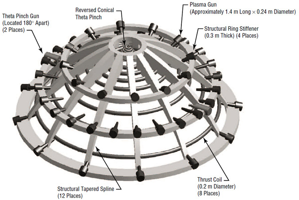
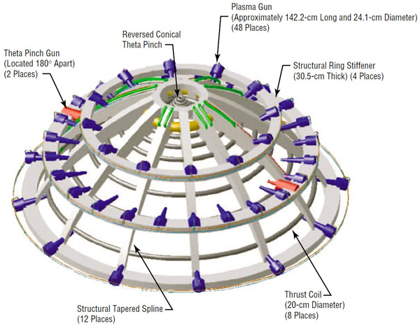
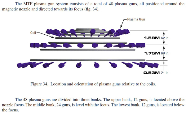
Two theta (Θ) pinch guns fire magnetized blobs of easily ignitable fusion fuel plasma on a collision course. They collide at the parabolic focus of the magnetic nozzle. The nozzle is a magnetic field formed by the thrust coils, because a nozzle made out of matter would be damaged by the fusion explosion.
Pink target is where the two blobs of deuterium/tritium fuel fired by the theta pinch gun collide. The 48 plasma guns fire the yellow plasma jets which form the liner.
A split second behind the firing of the theta pinch guns, a battery of 48 plasma guns fire plasma jets targeted at the fusion fuel blob. These jets form a spherical "liner" around the fusion fuel.
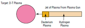
The inner part of the liner is deuterium while the outer part is hydrogen propellant
The jets are actually composed of two different plasmas. The inner bit is fusable deuterium, the large outer part of the jet is hydrogen propellant.
The liner collapses at about 750 kilometers per second and squeeze the fusion fuel like a nutcracker from hell. The fusion fuel ignites like a miniature H-bomb, which it is.
The important points are that D-T fusion is easy to ignite (Lawson criterion of only one), but the reaction emits a relatively large amount of damaging neturons (79%) and uses expensive tritium. D-D fusion is much harder to ignite (Lawson criterion of 30), but the reaction only emits 38% neutrons and deuterium is very cheap. The idea is that the liner will ignite the D-T fuel blob in the center, and the fusion explosion will be enough to ignite the D-D fuel in the liner.
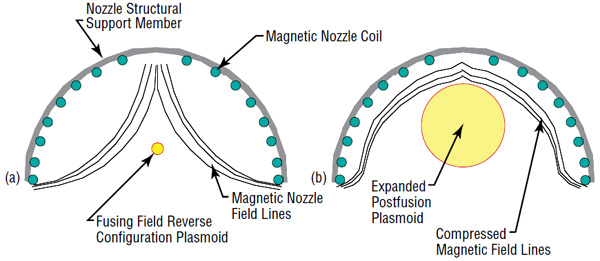
The thermonuclear detonation drives the hydrogen propellant in the liner outwards, where it rebounds off the magnetic nozzle, producing thrust on the thrust coils, which produce thrust on the structural tapered spines, which produce thrust on the thrust frame of the spacecraft's spine.
Magnetic nozzle configureation (a) at fusion ignition and (b) after propellant expansion. Compressed magnatic field lines produce upward thrust on nozzle structural support member
A large tank of water perched on top of the magnetic nozzle acts as an anti-radiation shadow shield, to protect the crew.
As is standard operating procedure with many such pulse engines, some of the energy of the detonation is tapped and stored in capacitors. This energy is used to power the next pulse (for the plasma guns and to create the magnetic nozzle). Electrical current is induced in the coils as the plasma cloud expands. Each plasma gun has its own capacitor to store power for the next pulse. The energy for the magnetic nozzle is stored in something called a Superconducting magnetic energy storage (SMES) device, located just below the nuclear reactor.
For the first pulse each of the capacitors and the SMES has to be slowly charged up by the nuclear reactor (since the poor little one-lung SP-100 can only crank out a pathetic 300 kilowatts). With subsequent pulses the capactors are recharged almost instantly, by the power of nuclear fusion.
VARIANTS
Deuterium-deuterium fueled 180-day stay option
Deuterium-deuterium fueled 180-day stay option
Deuterium-deuterium fueled 180-day stay option
Deuterium-Helium 3 fueled 180-day stay option
GALLERY
artwork by Winchell Chung (yours truly) click for larger image
Zeta-pinch or z-pinch is a technique to compress fusion fuel plasma to the point where it ignites a fusion reaction. You send a bolt of electricity through a cloud of fusion fuel. The electrical current induces a magnetic field in the plasma that squeezes the plasma towards the bolt.
Since you are trying to squeeze the plasma to fusion ignition densities, the bolt of electricity has to be so gigantic that it makes a terrestrial lighting bolt from a thundercloud look like a spark of static electricity on your kitty-cat. We are talking several megamperes here. This is created using a gargantuan bank of capacitors, which can store large amounts of electricity and release the entire charge in a fraction of a second. No more than 100 nanoseconds in fact.
As is common with pulsed-fusion rockets, part of the energy of the fusion explosion is diverted to re-charge the capacitor banks. The rest of the explosion is used to create thrust. The initial capacitor charge comes from a little one-lung fission reactor which ploddingly fills up the capactors over the course of a few days. The subsequent charges are created in microseconds by the reaction of the fusion explosion compressing the magnetic field inside the magnetic nozzle.
As anyone who is familiar with electricity knows, you ain't gonna get a bolt unless you have both a cathode and an anode. That is, an electrical hot point (cathode) hooked up to the capacitors, which is positioned reasonably close to an electrical cold point (anode) connected to "ground". The bolt jumps from the cathode to the anode, completing the circuit.
The point is that while it is easy to put the cathode on the nozzle spraying the jet of Deuterium/Tritium fusion fuel, placing an anode on the other end of the D/T jet is a bit of a challenge. You cannot use a solid metal anode because the fusion explosion will shred it. Replaceable solid anodes have the problems of replacing the shredded prior anode at a rate of ten times per second, and carrying along a sufficient supply of replacements.
In addition, the D/T jet (and future site of the fusion explosion) has to be somehow surrounded by a shell of lithium vapor. The lithium will act as propellant, secondary fusion fuel, and neutron shielding all in one.
The engine designers figured out to use these two problems to solve each other. The lithum vapor is sprayed as a hollow tube, with the D/T jet sprayed down the empty axis of the lithum tube. Actually the lithum is sprayed more as a hollow cone, with the wide cone base at the nozzle part and the point of the cone right at the far end of the D/T jet. Right where we want the anode, as a matter of fact.
Did I mention that the electrical ground is connected to the lithium nozzles?
So the electrical circuit is
Capacitor banks to
D/T nozzle to
Base of D/T jet to
Body of D/T jet to
End of D/T jet to
Bolt of electricity to
Cone tip of lithium cloud to
Cone body of lithium cloud to
Lithium nozzles to
Electrical ground
Megamperes of current pass through the electrical circuit creating the zeta-pinch to compress the D/T fuel. The fuel explodes in a fusion reaction. The lithium cone cloud does a bit of fusion itself, sops up some of the deadly neutrons, is coverted into high-velocity exhaust and created thrust. Part of the recoil of the lithium plasma on the magnetic nozzle is harvested to create electricity to recharge the capacitor banks.
The exhaust pulse is an expanding cloud of plasma with a total mass of 0.02 kilograms with a kinetic energy of one gigajoule. Each pulse creates 3,812 Newton-seconds, and there are 10 pulses per second (10 Hz). The effective specific impulse is 19,436 seconds. The ship acceleration is measured in milli-gees, but the specific impulse is fantastic.
This is channeled by a magnetic nozzle, since any nozzle made out of mere matter woud be damaged or vaporized by the ravening might of nuclear fusion. The recoil of the exhaust plasma imparts thrust to the magnetic field, which thrusts the magnetic coils, which thrusts the structural girders of the nozzle, which thrusts the spacecraft's thrust frame. The rest of the spacecraft is attached to the thrust frame.
Since the lithium cloud does a disappointing job of shielding the ship from neutron radiation, there is also a hemispherical radiation shield over the upper part of the magnetic nozzle. This is a three layer neutron shield and is one quarter of a meter thick (25 cm). The lithium hydride layer slows some neutrons and absorbs others about twice as efficiently as water. The boron carbide layer captures thermal neutrons. A thin layer of tungsten is added to reduce gamma rays.
There is also beryllium shield in between the radiation shield and the capacitor banks to deflect more gamma rays.
Z-Pinch freighter card from the game High Frontier (Colonization Expansion).
Single Decade Module 2 (DM2) capacitor modulue
Clusters of DM2 capacitors
Z-pinch engine has eight sets of dual DM2 capacitor modules on top of magnetic nozzle. The blue thing is the beryllium secondary gamma ray shield
MAGNETIC NOZZLE
magnetic coils (yellow) inside stuctural frame (gray)
Magnetic coil spacing
Fusion detonation inside magnetic field created by magnetic coils (red discs)
click for larger image
artwork by Winchell Chung (yours truly) click for larger image
The idea is to use miniature thermonuclear bombs for propulsion.
Currently the only practical way to ignite a fusion reaction in a measure of deuteriun fusion fuel is to heat it up with a fission explosion. The problem is that conventional fission devices require a minimum amount (a critical mass) of uranium, which is inconveniently large (several kilograms instead of micrograms).
As it turns out, antiprotons (i.e., antimatter protons) can cause a lump of uranium 235 to detonate in a fission explosion even if the lump is only a tiny fraction of a critical mass. One antiproton hitting a U235 nuclei will annihilate a proton, disrupting the nucleus. This will release neutrons, not one or two, 143 of the freaking things!. It only takes a few disrupted nuclei before a self-sustaining fission chain reaction is ignited, even in a lump that is way below critical mass.
So antiprotons hitting a small pellet of mixed fission and fusion fuel will make a tiny thermonuclear bomb. A beam of antiprotons from an antiproton gun will make the fission fuel detonate, and the energy of the fission explosion will cause the fusion fuel to detonate. Instant mini-thermonuclear bomb: just add antiprotons.
Fuel Pellet
The report says that 140 nanograms of antiprotons corresponds to about 1017 total antiprotons.Wikipedia says one antiproton has a mass of 1.672 621 923 835 748 933 04×10-24 grams. Times 1017 gives a mass of 167 nanograms, which is close enough to 140 for government work.
Into each pellet the antiproton gun will fire about 1011 antiprotons (I calculate about 0.000167 nanograms) with an energy of 1.2 MeV and a pulse length of two nanoseconds, focused into a volume of one cubic millimeter. In the diagram above, note the antiproton beam entering stage right, entering the Injection Hole. This implies that 1017 antiprotons contains about 106 antiproton bolts with each bolt containing 1011 antiprotons.
Each pellet is 3.0 grams of mixed fusion/fission fuel: molar ratio of 9:1 deuterium-tritium (DT) to uranium-235. In the diagram, the fusion fuel is the region labeled DT, and the uranium-235 is the tiny hemisphere to the right labeled U235.
The report does not go into details, but the pellet has a shell of non-fissile uranium-238 (labeled U238 in the diagram above). The report just mentioned that the antiproton beam hits the shell on the way to the uranium-235, and somehow this makes the fission triggering process easier.
When hit by the antiprotons the fuel pellet blows up with a 302 gigajoule thermonuclear explosion (about equal to 72 metric tons of TNT). The proportions of energy produced in the target are 83% radiation, 15% neutron kinetic energy, and 2% random ion and electron kinetic energy.
The pellets are detonated at the rate of 1 Hz (one per second).
The blast energy will be used to vaporize a layer off a solid slab of propellant (silicon carbide SiC). Since the energy spectrum of the blast is not the best to vaporize SiC, each fuel pellet will be coated with a spherical shell of 200 grams of lead (in the diagram above this is labeled "W-Shell"). This will absorb and re-emit the energy in an energy spectrum more suited to frying the heck out of the SiC. As a side-effect, the lead will reduce the blast energy from 302 GJ to about 204 GJ but you can't have everything. The lead shell is called a WLS in the report, but they do not explain the acronym.
The propellant slab is in the form of a hollow sphere of SiC with a large hole in one side. Actually the hole is so large that the sphere is more a hemisphere or spherical sector. The hole acts like the rocket exhaust nozzle. The fuel pellets are detonated at the center of the sphere, the blast vaporizes 0.8 kilograms of propellant from the interior of the shell, which shoots out the exhaust nozzle at 132,000 freaking meters per second (specific impulse of 13,500 seconds or about 30 times better than the best possible chemical engine). This produces a thrust of 100,000 newtons, which makes an ion drive look it has about as much thrust as a spray-can of underarm deodorant.
The SiC slab is a spherical sector of a sphere with a radius of 4 meters.
Now the report says the propellant mass for the Mars mission is 362,000 kg, but is a little vague as to whether that is just the mass of the silicon carbide, or the SiC plus the mass of the pellets. I am going to assume it is both, but I could be wrong. If this is true, my calculations say each detonation expends one 0.203 kg pellet, 0.8 kg of silicon carbide, and 0.000167 nanograms of antiprotons. Total of 1.003 kg per detonation. This means 362,000 kg of propellant is a total of 360,917 detonations, 73,266 kg of pellets, 288,733 kg of silicon carbide and 3.6×10¹⁶ antiprotons (with a total antiproton mass of 60 nanograms). Use these figures at your own risk, my assuptions could be mistaken.
Since the thrust is in pulsing jolts every second instead of being continuous, the spacecraft will need lots of shock absorbers between the engine and the spacecraft proper, just like an Orion drive. Otherwise the ship will be shaken into pieces.
Those crew modules on the long booms had better be folded upwards during acceleration. They are way outside the safe shadow cast by the anti-radiation power shield click for larger image
"Targets" are fission/fusion fuel pellets click for larger image
In an earlier design, the fuel pellets were compressed by an array of ion guns for added efficiency click for larger image
Radiation Shielding and Power Generation
Figure 2
"Targets" are the fuel pellets click for larger image
The thermonuclear reaction is deuterium+tritium which unfortunately is 79% neutrons, spraying from the engine. Those slippery little devils can do three different kinds of damage to the structure of the spacecraft, can prematurely detonate the entire stock of fuel pellets, can cause the containment system of the antimatter storage ring to fail, and give the crew cancer.
In Figure 2, the "Power Shield" is intended to prevent this unhappy state of affairs. It is a radiation shield composed of a 1.2 meter thick slab of lithium hydride. This protects the fuel pellets held in the "target storage" ring, the antimatter in the antiproton ring, and the crew in the crew module. Actually the crew module has an additional crew shield to further reduce the radiation dosage to 0.3 Sieverts over the 120 day mission.
Naturally stopping all this neutron radiation is going to heat up the power shield something awful. The shield will be cooled off by a liquid droplet radiator, getting rid of about 60 megawatts of waste heat (see Figure 3). In the spirit of "waste not, want not", some of the heat will be used to run a 10 megawatt electrical power generator (see Figure 2).
Figure 3 Liquid Droplet Radiator
There also appears to be two Mars landers docked just forwards of the target storage ring click for larger image
Thrust and Isp
Figure 4. Thrust and Isp Versus Propellant at 1 Hz firing rate.
For calculating thrust and specific impulse, the report is assuming use of the 200 gram lead shell around each fuel pellet.
The report states that the chart in Figure 4 shows with an ejected silicon carbide propellant mass per shot of 0.8 kilograms the thrust is 100 kN. I don't know about you, but to me the chart says thrust would be below 90 kN. Something does not add up here.
Assuming 100 kN of thrust, on the outbound leg of the mission the engine can boost the ship up to the required 25 km/sec delta-V in about three days flat. Igniting that many fuel pellets will require 30 nanograms of antiprotons total. If I am doing the math correctly, the ship will need an additional 30 nanograms of antiprotons for the return leg of the mission.
Report goes on to say that if you need 100 km/sec delta-V given an engine with a specific impulse of 13,500 seconds and a dry mass of 345 metric tons, you will need 362 metric tons of propellant. This is a mass ratio of 2.05. However, a later table in the report says the Mars mission total delta-V is 120 km/sec, not 100 km/sec. I guess the report was not properly proofread.
The report figures that out of the 302 gigajoules of energy released by the detonation of each pellet, only 7.1 GJ actually manages to accelerate the ship. The rest becomes waste heat of various kinds. Since the pellets are ignited once per second, the acceleration power is 7.1 gigawatts.
click for larger image
click for larger image
Antimatter-catalyzed fission-fusion Gigawatt Thruster patent card from the game High Frontier (3rd ed).
Silicon Carbide Ablative Nozzle patent card from the game High Frontier (3rd ed). Though the pictured system is using lead capsules containing positronium (Ps)
Dr. Robert Bussard promoted using an IEC inside a charged-particle electric discharge engine (QED), where the IEC generates an electron beam which vaporizes liquid hydrogen propellant. Dr. Miley thinks it is technologically more risky to try and develop two young technologies (IEC and QED) as opposed to developing one young technology and integrating it with a mature technology (IEC and magneto-plasma-dynamic (MPD) drives).
A IEC fusion reactor is attractive for use in spacecraft propulsion since it has an ultra-low alpha (kilograms per kilowatt) compared to other types of fusion reactors. On a spacecraft Every gram counts.
Current IEC designs produce ~106 neutrons per second using deuterium-deuterium fusion. For this engine the goal is to increase the power density by several orders of magnitude and convert it to D-3He fusion (to reduce the deadly neutron radiation). The aim is to produce about 21.4 MW of power.
A Direct Energy Converter (DEC) converts the IEC energy into a megavolt DC. An electrical system transforms the voltage and current to levels required by the MPD drive. Hydrogen propellant is used by the MPD drives to achieve the necessary thrust and specific impulse. The spacecraft is capable of traveling from Terra to Mars in 120 days.
In the table I had to play with the figures. One part of the report said the total mass of the propellant and tankage was 120,000 kg, another part said just the propellant mass was 127,500 kg. Both of these cannot be true simultaneously. For the table I used 127,500 kg for propellant mass and used Zubrin's general rule to estimate the tank mass at 12,750 kg (10% of propellant mass for orbit-to-orbit ship). The report said the habitat, cargo, and shielding was 60,000 kg; I reduced it to 42,950 kg to keep the wet mass at the reported total of 300,000 kg. As always the figures I calculated instead of taking from the report are shown in yellow.
IEC: fusion reactor DEC: converts fusion energy into electricity Step Down: massages electricity into a form the thrusters want Thrusters: magneto-plasma-dynamic rocket engines Fuel Tanks: hydrogen propellant. 14 tanks that are 50 m long
A quick Blender sketch I did using what details I could scavenge from the report.
For the step-down converters I used the capacitor array from the HOPE Z-Pinch Fusion
Since the MPD thrusters are 12 cm x 12 cm they are barely visible dots.
And in reality the DEC is packed full of blades that would obscure the view of the IEC.
Inertial Electrostatic Confinement (IEC)
The IEC is fairly standard: two concenric spherical grids. The inner grid is the cathode, charge to a huge negative potential. The outer grid is the anode, grounded. When D-3He fusion fuel is puffed into the grids, the high electrical field ionizes the gases and accelerates them towards the center. Because of the space charge build-up of ions and electrons, virtual anodes and cathodes are formed to augment the fields. The fusion fuel is squeezed to form a dense center where fusion occurs.
How fusion rate scales with current
Graph shows I5 rate and the more pessimistic I3 rate. Report assumes I5 rate can be achieved.
click for larger image
Figure 3. IEC fusion rocket power flow chart
P0 = 4.16 MW
P1 = 21.40 MW
P2 = 17.12 MW
P3 = 16.26 MW
P4 = 12.00 MW
P5 = 6.00 MW
Pexcess = 0.104 MW (available for life support, comms, experments, etc.)
IEC has an attractive fusion energy gain, turning 4.16 MW of injected power into 21.4 MW of output. The design gives a thruster power of 10 MW.
Estimated component efficiencies
COMPONENT
EFFICIENCY
Direct Electric Converter
ηDEC = 0.80
Step-Down Converter
ηSTD = 0.95
MHD Thruster
ηTH = 0.50
The IEC will have to deal with gas control. Fusion reaction products such as tritium will accumulate in the core and must be removed. More seriously, only 5% of the D-3He fuel is actually burnt. The unburnt fuel must be either retained in the core or removed and reinjected. 3He in particular is very expensive, it must either be manufactured. Alternatively it must be laboriously mined from either Lunar regolith or Saturn's atmosphere.
Grid Heat Removal
The inner and outer grids of the IEC control the fusion fuel to create the reaction. Unfortunately this means they are bathed in the star-core hot fusion fire. The outer grid can get rid of waste heat by simple radiative cooling but the inner grid will need an active forced cooling or the blasted thing will melt.
Both grids are geodesic spheres composed of a network of equilateral triangles, structures Buckminster Fuller would have loved. To control fusion they need a transparency of 95%. This means the d/a ratio has to be less than 0.0577 (d = grid tubing diameter, a = length of triangle side). The inner grid has a radius of 0.75 meters, d = 0.0127 m, and a = 0.22 m.
As a side note the outer grid has a radius of 6 meters, which is more or less the radius of the IEC.
The grid is constructed of tungsten, melting point of 3,683 K. The waste heat is 4.16 MW, of which one-third will hit the inner grid (1.39 MW). The inner grid can radiate away 110 kW of waste heat, which means that 1.28 MW of waste heat will have to be taken care of by the coolant system. Hydrogen will flow through the cooling channels at a mass flow rate of 61.4 g/sec, leaving the grid at 1,420 K. There it enters 200 m2 of heat radiator, exiting the radiator at 300 K.
Of the 4.16 MW of waste heat, 2.77 MW of that will not hit the inner grid so will strike the outer grid. Since the outer grid can handle up to 2.87 MW of waste heat by radiative cooling, this is not a problem. The outer grid will not require a coolant system.
Shielding
The habitat module is 10 x 5 x 3 meters, surrounded by polyethylene shields of 9 g/cm2 to shield against solar particle radiation. The shield mass is 17.1 metric tons. In case of an "anomalously large solar flare" (i.e., the mother of all proton storms) the shielding can be moved to make a tiny triangular storm cellar of 2.5 x 2.5 x 3 meters with 18 g/cm2 of rad shielding. The goal was to keep the radiation exposure under 47 Rem for the 270 day mission.
The other problem is the neutron radiation from the fusion reactor. Yes, the D-3He reaction emits no neutrons. But it is impossible to prevent stray deuterium ions from reacting with other deuterium ions instead of helium-3 ions like they are supposed to do (technical name is "side-chain reactions"). D-D reactions do make neutrons. What's worse is it also creates tritium ions, who will promptly reaction with deuterium to make even more neutrons.
The report figures that 8.69% of the reaction will be the nasty D-D kind, which at this power level will create 3.475 × 10¹⁷ neutrons per second, plus creating tritium. The report figures that pretty much all the tritium will react with deuterons, producing more neutrons for a total neutron flux of 6.95 × 10¹⁷ neutrons/sec.
To protect the habitat module and crew, the hydrogen propellant tanks will be in the form of 50 meter long tanks set directly in between the hab module and the fusion reactor. This will thermalize the neutrons so they can be absorbed by the hydrogen. The report calculates that only a negligible amount of neutrons will reach the hab module, even when the propellant tanks are at minimum residual levels at the end of the mission.
Direct Electric Converter (DEC)
Cross-section view of the DEC outside of the IEC
For simplicity only representative collector plates are shown. In reality the thing will be jam-packed with plates.
The DEC intercepts all the energetic fusion reaction product particles that come screaming out of the reactor like a bat out of hell, and converts their energy into electricity. This feeds the MPD thrusters.
The fusion products are 14.7 MeV protons and 3.5 MeV alpha particles. Plus additional particles from those pesky side chain reactions. All the charged particles can have their energy harvested, that is everything but those worthless and dangerous neutrons.
The DEC uses blades of metal arranged like Venetian blinds as electrostatic energy converters. The collectors are charges to a potential slightly below that of the particle they are harvesting. The 1.5 MV blades suck up the tritium atoms from the side chain reaction, the 3 MV blades suck up the alpha particles from the side chains and the main reaction, and the 14 MV blades suck up the torrent of protons from the main reaction.
The 14 MV blades are set perpendicular to the proton flux, that is, tangent to the spherical surface. The protons are the bulk of the energy and the DEC doesn't want to let any get away.
The 1.5 MV and 3 MV blades are more of a "waste not, want not" feature. This means any additional energy they harvest is welcome, but only as long as they do not interfere with the outer 14 MV blades gathering protons. So the 1.5 and 3 MV blades are set almost edge-on to the reaction product flux, so as to avoid shadowing the outer 14 MV blades from the flood of protons.
As the blades slurp up the fusion reaction products, the collision can cause secondary electrons to be emitted. This can result in unwanted leakage currents between the high voltage plates, aka gigantic bolts of lightning wrecking the thing. To avoid this unhappy state of affairs electron suppressor grids are added. They are charged to a negative 0.1 MV. Note that each suppressor grid is in the shadow of a blade because the fusion products will damage them.
Since these blades are charged with megavoltage, they cannot be placed too closely or electrical arcs will be struck and short-circuit the DEC. A 1.5 MV blade cannot be closer than 53.3 centimeters to a suppressor grid, a 3.0 MV blade cannot be closer than 103.3 cm to a suppressor, and a 14.0 MV cannot be closer than 407 cm to a suppressor.
Each blade has a length of 5 cm. So the DEC system will have an outer radius 7.54 meters beyond the outer grid of the IEC. Since the IEC radius is 6 m, the total radius will be 13.54 meters.
Step Down Converter
The electricity produced by the DEC has to be converted into a form suitable for the MPD thrusters (and a bit to run the IEC). This means the 14 megawatt potential output has to be transformed into 1 kilovolt at 104 amps. The thrusters also need the electricity in the form of 10,000 pulses per second, this can be created by a capacitor storage system.
The step down converter uses the principle of an electrostatic generator. The 14 MW charge on the DEC induces a charge on a probe connected to a capacity. A relay connects the capacitor to ground, allowing the probe to charge up the capacitor. When it is full, the relay clunks over and switches the connection from ground to a connection to the MPD thruster.
Magneto-plasma-dynamic Thruster
"Electric Current" means "High-voltage arc"
The thruster has a specific impulse of 3,000 seconds, an exhaust velocity of 29,430 m/s, a propellant mass flow of 2.3 g/s and a thrust of 68 newtons per thruster. There are five thrusters for a total thrust of 340 N. The efficency is only 50% but the output is pretty good considering. Each thruster has an average power input of 2 MW with a peak power of 10 MW.
Hydrogen propellant is continuously fed into the thrust chamber (which is 6 cm x 3 cm) at a rate of 2.3 g/sec. The cathode and anode are connected to a capacitor bank. When the electrodes reach a potential of 1 kilovolt (i.e., when the relay connects the capacitor to the electrodes) an arc strikes between them with a current of 20 kiloamps. This dissociates and ionizes the hydrogen, sharply raising its pressure (just like an arcjet). The increased pressure accelerates the ionized hydrogen into the conical nozzle. There the azimuthal magnetic field generated by the arc accelerates the ionized hydrogen further (just like an MPD drive). It exits the exhaust nozzle at 29,430 m/s, creating 68 N of thrust.
The thruster has a pulsing frequency of 10,000 per second. This increases the chamber pressure and prevents overheating. By the time a cloud of ionized hydrogen exits the exhaust nozzle, another arc has ionized a new slug of hydrogen propellant.
The three atmosphere pressure increase caused by the arc has several benefits. Hydrogen dissociation and ionization losses are reduced. The Reynolds number is increased. And when the ionized hydrogen enters the conical nozzle, it starts recombining which further accelerates the exhaust velocity. The increased Reynolds number reduces frictional forces on the walls of the thruster.
Each thruster has three main components: Electrical, nozzle frame, and copper heat radiator.
The nozzle and propellant feed tube are constructed from an insulator with a high melting point, such as Silicon nitride (Si3N4). The electrical components include the capacitor (double line symbol), the cathode at the base of the thruster, and the anode at the exhaust nozzle mouth.
Each thruster requires 13 m2 of heat radiator, made of copper, with a radiator mass of 700 kg.
The estimated mass of a thruster is 1,760 kg; 8,800 kg for all five thrusters.
Propellant Tanks
The propellant mass flow during a burn is 11.5 g/sec. For the 120 day acceleration period part of the mission it will require 127,500 kg of propellant, plus a 5% reserve. The propellant is liquid hydrogen, requiring a volume of 1,960 m3. This will be divided among 14 tanks, each 50 meters long. As is customary the propellant is located between the hab module and the reactor to provide radiation shielding.
I played around with the cylindrical tank equations. At a rough guess, if the cylindrical part of the tank had a height of 48.2 meters and a radius of 0.95 meters, and the end-cap spheres had a radius of 0.95 meters; one tank would have a volume of 140 cubic meters. Fourteen such tanks would have a total volume of 1,960 m3.
The designers wanted a power source that had a mass of about 180 metric tons that could crank out 750 megawatts continuously for a year. This has an admirable alpha of 0.24 kg/kW. The 14.7 MeV protons produced by D-3He fusion reaction are sent through Travelling Wave Direct Energy Converters (TWDEC) to harvest their energy. This has a theoretical maximum efficiency of 90% but will probably have something closer to 75% in the real world.
This high level of electricity is needed because ion drives are notorious energy gluttons. They accelerate argon propellant up to 343,000 meters per second, for a jaw-dropping specific impulse of 35,000 seconds. But like most propulsion systems the high specific impulse means a pathetic thrust, in this case a measly 56 Newtons per engine (about 1k hummingbirds). Fusion Ship II has an array of 78 ion engines but that is still only 4,369 N. This means the initial acceleration is only 0.0087 m/s (not quite 2 snailpower) but you can't have everything. The point is the ion drives can get the ship from Terra to Jupiter in 0.58 years instead of 2.75 years, almost five times faster.
Payload includes electronics, crew compartment, equipment, shielding, consumables, life support, shield tanks, heat radiator.
click for larger image
Fusion Ship II is one-quarter the mass of the Space Shuttle but is more than five times the length. This means Fusion Ship II is very non-dense, i.e., it is practically made out of gossamer and thistledown. The designers wanted it to be as low mass as possible, but it had to be long due to radiation concerns and constraints brought by the fusion power plant
With Isp = 35,000 s and total flight time of 362 days, the final mass is about 270,000 kg
IEC fusion reactor
The Fusion Ship II has two stacks of five reactors each
Particle Flow Diagram
The reactor is fed deuterium at a rate of 83 kg per year (0.0095 kg/hr) and fed helium-3 at a rate of 125 kg per year (0.0103 kg/hr)
Protons from the fusion reaction are sent through the Travelling Wave Direct Energy Converters for conversion into electrical power
Leaking fuel/fusion products are sent to fuel processing. As much of the unburnt deuterium and helium-3 as possible is skimmed out and sent back to the reactor. The tritum and helium-4 waste products are jettisoned.
Inertial electrostatic confinement / Travelling Wave Direct Energy Converter power flowclick for larger image
In-A.22 Nikto-ega class interceptor
Nikto-ega Interceptor
Propulsion
Cascade drive
ΔV
1,013,000 m/s
Wet Mass
6,590,000 kg
Dry Mass
2,012,000 kg
Mass Ratio
3.28
Exhaust Velocity
852,800 m/s
Specific Impulse
86,900 sec
Thrust
309,568,480 N
Thrust Power
132 terawatts
Acceleration
4.1 to 6.7 g
Acceleration
40.2 to 65.7 m/s
Length
66 m
Beam
18 m
Crew
3
Armament
2 x ion cannon (9.2MW), Missiles
Hyperdrive
none
This is a design by Juho Kesälä, artist and long-time student of this website. It is amazingly good! I cannot find anything scientifically inaccurate, and only minor quibbles with the design.
The propulsion system is called the "cascade drive", which from the description appears to be a species of antimatter-catalyzed-microfission Hydrogen-Boron fusion. The specific impulse for the cascade drive is a bit more than the info I have about the HB drive but it is in the same order of magnitude. Fuel pellets containing Hydrogen-Boron and Uranium 235 (in a 9:1 molar ratio) are fired into the center of a magnetic nozzle. Antimatter beams shoot streams of antiprotons at the pellet. The antiprotons cause the uranium to fission. The fission energy ignites the hydrogen-boron fuel into a fusion reaction. The magnetic nozzle turns the fusion energy into thrust. The pellets are ignited at about 1 second intervals.
In fleet combat, the tiny Nikto-egas are interceptors. Their relatively high acceleration and delta-V give them a huge reach. The main function is to intercept hostile missile fire in the early boost stage. The idea is the threat of the intercepter forces the missile to shed their high delta-V boost stages, or be destroyed by interceptor ion cannon fire. Without the boost stage, the missiles can no longer reach their original target, so they have to retarget on the relatively low-value interceptors. The interceptors are designed to survive this, but interceptor attrition rates are inevitably high.
To endure the savage four to eight gee acceleration, the 3 man crew uses liquid breathing. This is appropriate since "nikto-ega" is a species of small predatory fish.
The interceptor can carry up to four mission-specific payload pods. These include missile pods, electronic warfare, sensors, and drones.
Fuel pellets are fired from fuel pellet guns along the green path. At the detonation point the pellet is hit by a beam of antiprotons from the antimatter igniter booms, firing along the red paths. The fusion energy is reflected off the abalative pusher to produce thrust.
The antimatter igniter booms also contain the catchers for the droplet radiators. The light blue area at center left shows the path of the radiator droplets. Me drawing on top of Mr. Kesälä's artwork
This fusion ship uses John Slough et al's innovative Magneto Inertial Fusion engine. The engine has most of the advanages of both magnetic confinement and inertial confinement fusion with very little of the disadvantages. Instead of trying to crush the fusion fuel with wobbly magnetic fields or a spherical firing squad of lasers, then attempting to heat the propellant by toasting it over the explosion, it tries a more clever method.
Instead it magnetically crushes a foil ring of lithium metal (called a "liner") such that it also crushes a blob of fusion fuel in a mighty fist of metal. Then as the fusion explosion occurs, the lithium becomes propellant, conveniently totally enclosing the blast and doing a fantastic job of converting fusion energy into propellant energy. This also allows the rocket to use open cycle cooling, so it does not need acres of heat radiators like other fusion rockets.
In addition, carrying inert rolls of compact lithium foil propellant is infintely easier than trying to keep huge cryogenic tanks of liquid hydrogen from boiling dry.
Each lithium foil liner has a mass of something between 0.28 to 0.41 kilograms. The crush speed is about 3 kilometers per second, resulting in a solid cylinder of lithium with a fusion explosion going off in its heart.
Using a fusion rocket means the entire mission will take about 210 days, instead of the 540+ days you'd need with a fission rocket. Which means the crew won't max out their career radiation exposure limit in one lousy mission.
For the specified mission a specific impulse of 5,000 seconds is needed. A complicated equation (in the paper) calculates this mandates a fusion gain factor of 200. This means if you want 36 megawatts of jet power coming out of the engine, you will have to feed in 36,000,000 / 200 = 180 kilowatts of electricity. This can be supplied with a low-mass arrangement of a solar photovoltaic array charging a capacitor energy storage bank (instead of being forced to use a weighty nuclear reactor or something). Remember that sunlight is weaker at Mars orbit, you'll need an array rated for 400 kilowatts at Terra orbit in order to eke out 180 kW at Mars.
The crew habitat module appears to be a bog-standard inflatable TransHab module, which is hardly surprising. It can house a crew of six for about 18 months in about 33 metric tons. The rest of the payload is a 30 metric ton Mars Excursion Vehicle. Basically it is using the payload package specified in NASA's Mars Design Reference Architecture 5.0.
SHADOW SHIELD protects ship from radiation FRC FORMATION makes the puff of fusion fuel for detonation (stands for Field Reversed Configuration if anybody cares) SHOCK ABSORBERS are needed since this engine pulses BANG! --- BANG! --- BANG! at 13.3 second intervals instead of a steady burn LINER/PROPELLANT INJECTOR converts a length of lithium foil into a ring and throws it over the compression coils MAIN COMPRESSION COILS grabs the ring of lithium foil and brutally squeezes it over the puff of fusion fuel MAGNETICALLY INSULATED EXPANDER channels the blast of lithium plasma into a rocket exhaust
White area is protected by the shadow shield. Note how radiators are trimmed at an angle to keep them inside the protective shadow.
This is a study that takes a mirror fusion experiment conducted at the Lawrence Livermore National Lab (LLNL) and extrapolates it into an actual space propulsion system, the Mirror Fusion Propulsion System (MFPS). It then compares the MFPS performance on a typical Mars mission between the fusion rocket and chemical, solid core nuclear thermal, gas core nuclear thermal, and nuclear electric. Mostly so it can point its finger at the other propulsion systems and laugh. The metrics used are Initial Mass in Low Earth Orbit (IMLEO), mission flexibility, and flight times.
The main tasks of coverting the fusion experiment into an actual rocket are of course maximizing the fraction of fusion energy that actually creates thrust, and getting the mass of all the components down as low as possible. Which is generally true of all rocket propulsion.
TL;DR: the MFPS can theoretically get the flight time Terra-to-Mars down to 60 day, with an IMLEO of 1,000 metric tons. It also allows a return-home capability at any time, instead of having to wait for Mars and Terra to be in the proper orbital angles.
Low flight times are always good. There currently isn't any good way to shield the crew from galactic cosmic radiation (short of using all your payload mass on radiation shielding), so reducing the flight time also reduces the dose. In addition, centrifuges or other forms of artificial gravity increases design complexity, increases the risk of malfunctions, and lowers the payload mass. Lowering exposure to free-fall reduces the medical damage to the crew. It would be real nice if the landing crew had enough muscles left so they can move around on Mars without wheel chairs.
Return-home at any time is a fantastic bonus to crew safety that most Mars spacecraft lack. This allows an emergency return if a crew member suffers some catastrophic ailment that cannot be managed on the ship, or if some part of the life-support system starts to malfunction.
And as long as spacecraft are manufactured on Terra, IMLEO matters because you have to boost all that mass into orbit with a price tag around $4,000 US per kilogram.
Left: Simple mirror
Right: Comparision of three mirror designs
The engine uses magnetic confinement fusion, with the linear or magnetic mirror version. Inertial confinement fusion and magnetic confinement with toriodal coils tend to have more mass.
The original magnetic mirror system using simple mirrors would leak fusion plasma out both ends, which is counterproductive.
The "Tandem mirror" (TM) concept has the linear fusion chamber composed of a series of fusion cells, with smaller cells on either end to plug the leakage. The plug cells have a higher plasma density. Unfortunatly this increases the plasma temperature in the plug cells, resulting in extravagant losses of ions, electrons, and Bremsstrahlung x-rays.
The designers went with a new concept: Thermal Barrier Tandem Mirror (TBTM). This thermally insulates the plug cells from the main chamber, allowing the plug cells to have a lower plasma density, a lower plasma temperature, but still have a strong enough electrostatic field to plug the holes.
End Plugs
Left: the Mirror Advanced Reactor Study plug. Better than the TBTM, but boy is it bulky and heavy
Right: the superior MINI-Mirror Advanced Reactor Study plug. Short, compact, and lower mass.
Fusion engines of this type use the fusion reaction products as propellant, so one wants to use fusion fuel whose reaction products contain the greatest proportion of charged particles. Otherwise it is almost impossible to get any thrust out of the exhaust.
The designers decided to go with Deuterium + Helium-3 fuel, since it fuses with a remarkable lack of nasty neutrons. Neutron radiation is dangerous to the crew, makes the spacecraft fragile by neutron embrittlement, and transmutes part of the spacecraft into radioactive isotopes by neutron activation. D+3He would be totally free of neutrons in the reaction were it not for a couple of fusion side chains.
You have to mix the optimal amounts of both deuterium and helium-3 in order to get the maximum energy converted into thrust and the minimum energy converted into waste products. Waste products include Bremsstrahlung x-rays, synchrotron microwaves, neutrons, and plasma transport heating. The chart above shows the four waste products and how they reduce the percentage of fusion energy that becomes thrust. The chart assumes the optimum plasma temperature of 90 keV.
Bottom line is the minimum waste/maximum thrust happens at a 3He to D mix of 0.5, or one helium-3 ion per two deuterium ions.
click for larger image
The chart above was used to determine the optimum temperature. It checked temperatures from 34 to 160 keV. Optimum turned out to be 90 keV.
So the optimum is a 3He to D fuel mix of 0.5 (one helium 3 ion per two deuterium ions) at a temperature of 90 keV. This results in 64% of the total fusion power remaining available for thrust, with the rest of the power going into waste products. This energy is used to heat the propellant.
The fuel will be injected in the form of tiny pellets of D-3He ice. Sadly the accelerator tubes that inject the pellets had to be short, which means the acceleration was high, which exceeded the stress requirement of the pellets. The designers figure on adding small amounts of Lithum-6, Lithum-7, or Beryllium-9 as a shell around the pellet to make it stronger. Sort of like Sixlets candy.
As with all high-energy propulsion, the engine will make distressingly large amounts of waste heat. This will have to be taken care of or the engine (and most of the spacecraft) will be melted or vaporized. The mass-intensive way to jettison waste heat is with large heat radiators. The low-mass way of getting rid of the waste heat is to have most of the engine in the form of skeletal frameworks that do not get in the way of the heat flying out into the inky depths of space. Most of the engine will be magnetic fields that are not affected by the heat.
The designers favor the latter strategy because Every Gram Counts and heat radiators weight tons.
The remaining skeletal parts of the engine that are actually made out of matter will need heat control. The two choices are active cooling (heavy heat radiators) or passive cooling (design the components so they act like blackbody heat radiators). Naturally the designers went with the latter.
The designed mirror fusion engine has a mass of 460,000 kilograms and produces continuous thrust. It produces 4 gigawatts of fusion power of which 2 GW becomes exhaust jet power. So the engine's specific power is about 4.3 kW/kg.
About 31 grams per second of plain vanilla hydrogen propellant is injected into the fusion reaction to create a thrust of 11,000 newtons. So the vehicle will accelerate at 1.0-to-1.5 cm/sec2 (0.010 m/sec2 to 0.015 m/sec2) with a specific impulse of 37,000 seconds (exhaust velocity of 360,000 m/s)
The engine will accelerate constantly over a prolonged period, like a nuclear-electric propulsion system (ion drive). It is just that the MFPS engine has a much higher acceleration than an ion drive.
This is just the engine. The payload, habitat module, and all the propellant tanks will be stacked on the end labeled "Crew Side"
The engine is about 79 meters long and 8 meters in diameter over most of its length.
Engine Component Masses
COMPONENT
METRIC TONS
CMC Central Mirror Cell
RRU Reflector-Radiator Unit
14
SCUs Shield-Coil Unit
168
CCUs Choke-Coil Unit
42
FPIA Fuel Pellet Injection Assembly
8
HCS High-Compression Structure
104
AMC/FMC Aft Mirror Cell Forward Mirror Cell
48
PDS Propellant Delivery Subsystem
6
PCS Propellant Cooling Subsystem?
14
ENA Exhaust Neutralizer Assembly
6
DCA Direct Converter Assembly
5
ATCS Active Thermal Control Subsystem
45
TOTAL
460
CENTRAL MIRROR CELL (CMC)
This contains the fusion plasma and keeps it both ignited and stable. The CMC is composed of the Reflector-Radiator Unit, seven Shield-Coil Units, two Choke-Coil units, a Fuel Pellet Injection Assembly, and a High-Compression Structure.
The high-compression structure support everything. The center is the reflector-radiator unit, threded through the seven shield-coil units. There is a choke-coil unit forwards and aft, and the fuel pellet injection assembly is forward of the front choke-coil.
REFLECTOR-RADIATOR UNIT (RRU)
This is the fusion reaction chamber. It does four things: [1] reflects synchrotron radiation back into the plasma so the energy is used for thrust instead of worthlessly escaping, [2] creates an image-current counter force to suppress plasma instabilities, [3] passively emits waste heat as a black-body instead of requiring a heavy heat radiator, and [4] is transparent enough to let most of the neutrons and over half of the Bremsstrahlung x-rays to freely escape into space instead of being absorbed and making the engine melt.
It is a thin-walled rippled tube composed of three layers: [1] inner layer of molybdenum foil 10 to 50 mm thick, [2] one centimeter thick middle layer of graphite, and [3] one centimeter outer layer of carbon fiber. The molybdenum reflects synchotron radiation, the graphite suppresses the plasma instabilities, the carbon fiber is the passive black-body heat emitter, and all three are reasonably transparent to neutrons and Bremsstrahlung x-rays. The RRU will have a minimum temperature of 2,200°C.
The seven Shield-coil units are threaded on the RRU like Cheerios on a toothpick. Some of the black-body heat and Bremsstrahlung x-rays from the RRU hits the shield-coils. That's OK, the shield-coils can take it. The energy is re-radiated from the shield-coils as heat, and any of the heat that hits the RRU is just re-radiated a third time.
WASTE POWER FLOW IN MFPS PBrem is Bremsstrahlung radiation Pn is neutron radiation Psyn is synchrotron radiation Px is plasma transport PIR is infrared (heat) radiation 1 is PBrem + Pn + Psyn + Px 2 is PBrem + Pn 3 is PIR click for larger image
In the above diagram, the vertical bar at the left is the hollow Reflector-radiator unit (RRU) containing the core fusion plasma. It is actually a vertical cylinder but is seen here in cross-section. The discs labled "SCU" are two of the shield-coil units in cross section, they are actually donut-shaped toruses with the RRU passing through their donut-holes.
What the diagram is saying is:
Some of the four types of fusion radiations (1) hits the RRU walls, is converted into infrared heat, and is passively emitted as black body IR radiation (3) into deep space.
Some of the Bremsstrahlung and neutron radiation (2) passes throught the RRU walls like they were transparent and head off into deep space.
Some of the Bremsstrahlung and neutron radiation (2) and IR radiation (3) strikes the SCU. It is converted into IR radiation (3). Some goes into deep space, some hits adjacent SCUs, and the rest hits the RRU walls again.
SHIELD-COIL UNITS (SCUs)
The engine has seven shield-coil units in the middle (the central cell coils), with each end of the central mirror cell closed with end-plugs. The mirror ratio is 5.0, meaning the magnetic field of each end-plugs is five times as strong as the field in the central mirror cell.
The SCUs produce a colossal 6.6 Tesla magnetic field to confine the reacting fusion fuel. The end-plug units produce an even more colossal 33 Tesla field to prevent the fusion reaction from blowing out either end.
The magnetic field is produced by superconducting coils, called the "winding pack." The SCUs have armor to protect the winding pack from the radiation emitted from the RRU. Otherwise they will not be superconducting any more, the fusion plasma will no longer be confined, and the sun-hot escaping plasma will void the engine's warranty with extreme prejudice.
The winding pack is kept cool with liquid hydrogen propellant. The mass flow rate of propellant determines how much radiation heat can be removed, which determines how thick the armor has to be. At the point where the temperature of the hydrogen rises to the winding pack's superconducting limit, the hydrogen is diverted to the propellant injection assembly and becomes thrust.
FUEL PELLET INJECTION ASSEMBLY (FPIA)
The fuel pellets have to be injected at high velocity, but even though the pellets are coated with lithium, the poor things are still basically made of ice and are fragile. The short firing path means they will have to be subjected to high acceleration, which is not fragile-friendly.
So the FPIA uses a two stage system.
Stage one is a centrifugal particle injector to reduce pellet erosion in the low-speed portion. Stage two is a railgun that boosts the pellet to a speed between 10 and 30 kilometers per second.
END PLUGS
Each end-plug mirror is composed of a choke-coil backed by an octopole. As previously mentioned it has a magnetic field with a jaw-dropping strength of 33 Tesla.
The aft plug is weaker than the fore plug, because that's where the rocket exhaust escapes. 94% of the fusion thrust power goes into the Exhaust Neutralizer Assembly to become thrust.
The other 6% exits the fore plug and enters the Direct Converter Assembly to become electrical power, to run the entire clanking mess.
HIGH-COMPRESSION STRUCTURE (HCS)
If you have ever played with magnets before, you know they attract each other. The more powerful the magnets, the more insistently they clank together. I might mention in passing that 33 Tesla is pretty freaking powerful.
At each end of the RRU you will find one each: a shield-coil unit, a choke-coil, and an octopole. All three are magnets, all three are fantastically strong, all three want to savagely clank together and all three are not taking "no" for an answer.
How do you keep these monsters apart? That's where the high-compression structure comes in.
They are composed of eight-to-sixteen massive load-carrying columns over the length of the three magnets. They are made of high-strength, high-temperature titanium boride. They are also laminated with carbon aerogel because they are located at the hottest parts of the engine. This is also to protect the fluid and utility lines that enter the choke-coils.
For design purposes, acceleration forces can be ignored because they will be smaller than the magnetic forces by four orders of magnitude (i.e., 1/10,000th).
Reactor Ignition Subsystem
The rocket uses D-3He for fuel, but that is hard to ignite. So they decided to start with an initial charge of Deuterium-Tritium fuel, since that is easier to light. DT has a Lawson criterion of only 1, D-3He is 16, which means it takes 16 times as much energy to initiate.
But once you have a DT fusion reaction going, that will easily ignite a D-3He reaction.
You start with DT fuel pellets and about five to six gigajoules of electricity dumped into the heating and magnet system over a 20-to-90 second period to ignite the DT plasma. The reactor is quickly brought up to self-sustaining levels. Plasma is bled off into the direct converter assembly to generate lots of electricity. The power is transferred to the superconducting magnetic coils to raise their Tesla levels up to normal operating levels. Now you can switch over to standard D-3He fuel pellets. The MFPS is now at 4 gigawatts thermal fusion power with 39 gigajoules stored in its magnetic fields.
When the report compares the Mirror Fusion engine with other engines, they use a standard vehicle. This is composed of the following:
Common Vehicle Components
COMPONENT
METRIC TONS
Payload (Landers)
100
Payload (Crew Module)
50
Structure & Avionics
30
Propellant
as per mission
Propellant Tanks
10% propellant mass
Engine
as per propulsion system
The ship has to deliver both the Landers payload and the Crew Module payload from Terra to Mars, but only has to return the Crew Module from Mars to Terra. The Structure and Avionics component includes vehicle struture, communications, attitude control (RCS), power systems, thermal control, and misc avionics.
Engine Assumptions
Engine
Specific Impulse (sec)
Engine Mass (kg)
Outbound
Return
CHEMICAL
475
10,000
3,000
NTR Solid Core
1,000
65,000
13,000
NTR Gas Core
3,000
90,000
NEP 20MW
90,000
NEP 50MW
120,000
NEP 100MW
165,000
NEP 200MW
200,000
MFPS
37,000
460,000
Engines with both "outbound" and "return" masses are two-stage rockets. The other engines are all single-stage.
Rocket engines that are chemical, nuclear thermal rocket solid core, and nuclear thermal rocket gas core perform missions with a series of discrete impulse burns. From Terra orbit they do a Trans-Martian injection burn lasting a few minutes then coast for a few months. Upon Mars approach they do a Mars Orbital Capture burn, settle into orbit, then orbit Mars while the landers ferry explorers to and from the Martian surface. At departure time they do a Trans-Earth injection burn for a few minutes then coast for a few months. And upon approaching Terra they do an Earth Orbit Capture burn and settle into orbit. This is called High Impulse Acceleration.
Nuclear electric (ion drive) and the Mirror Fusion drive use an alternate method. They have a lower acceleration than the other drives, but such a fantastic specific impulse that they can make the engine burn last for pretty much the entire Terra-Mars leg of the mission, and for the Mars-Terra return. Each of the two legs has three phases: escape spiral, heliocentric transfer, and capture spiral. This is called Low Continuous Acceleration.
Because these two strategies are so different, the researchers had to make two separate charts for figuring out the required delta-V. You can see them below:
Mission Chart for High Impulse Acceleration
Flight Time vs. angle traveled around Sun (Δυ)
Chemical, NTR solid core, NTR gas core
Mission Chart for Low Continuous Acceleration
Flight Time vs. angle traveled around Sun (Δυ)
Nuclear Electric (ion drive) and Mirror Fusion
The following charts are basically showing how pitifully frail the other propulsion systems are compared to the MFPS and the awesome might of nuclear fusion. The study authors are pointing their fingers and snickering, but in a dignified scientific manner.
IMLEO required for 240-day flight to and from Mars
IMLEO required for 210-day flight to and from Mars
IMLEO required for 180-day flight to and from Mars
IMLEO required for 150-day flight to and from Mars
IMLEO required for 120-day flight to and from Mars
IMLEO required for 90-day flight to and from Mars
Minimum IMLEO vs Flight Time for each propulsion system
This is another clever scheme to combine inertial confinement fusion (IC) and magnetic confinement fusion (MC). Remember that in both of the conventional schemes the longer you can confine the fusion plasma, the more of it will burn in nuclear fusion, and the more energy you will get out of a unit of fuel.
Conventional IC fusion has a naked pellet of fusion fuel surrounded by a circular firing squad (nay, spherical) of lasers. The laser pressure crushes the fuel until it ignites into fusion. Unfortunately the confinement lifetime is dictated by the speed of sound in the plasma, leading to lamentably short confinements.
Conventional MC fusion tries to confine hot fusion fuel plasma in a magnetic field. The complicated arrangement of magnetic fields still cannot prevent the plasma from wriggling out between the magnetic lines of force like a swarm of greased piglets. A material metal wall is not used to confine the plasma because
to the star-core hot fusion plasma the metal wall is colder than winter midnight at Antarctica. It instantly cools the plasma below fusion temperatures
to the metal wall the star-core hot fusion plasma is like an oxy-acetylene cutting torch on steroids. The metal wall's warranty will be terminated with extreme prejudice.
The clever Magnetically Insulated Inertial Confinement Fusion (MICF) scheme turns the concepts on their heads.
FUEL PELLET
Blue: Tungsten Shell (Metal Shell)
Green: Fusion Fuel (Halo)
Red Flare: Hollow Core (Plasma Core)
Red Arrow: Laser Beam
Green Arrow: Fusion Fuel Inner Radius
Blue Arrow: Fusion Fuel Outer Radius
Violet Arrow: Metal Shell Outer Radius
MAGNETIC FIELD FORMATION INSIDE FUEL PELLET
Unlike IC fusion the fuel is not a naked pellet. Instead it is a layer of fuel inside a hollow sphere of tungsten. There is a single hole allowing the entry of a 2.59 megaJoule laser bolt. Inside the sphere the bolt vaporizes the fusion fuel into plasma. Fusion is ignited.
The clever part is the geometry of the bolt and the plasma create a magnetic field which thermally insulates the tungsten from the hot plasma. Instead of the confinement lifetime being dictated by the speed of sound in the plasma, it is instead dictated by the shock speed in the tungsten.
The bottom line the confinement time is about two orders of magnitude (100 times) longer than with MC or IC fusion. The plasma burns longer and produces more fusion energy. With Deuterium-Tritium (DT) fusion fuel the expected fusion energy gain factor is a whopping 724.
MICF ENGINE
with pellet detail at lower left
Like most IC fusion engines the MICF engine has four main parts: pellet injector, laser, reaction chamber, and magnetic nozzle.
Pellets are injected at a predetermined rate (ω) into the reaction chamber, where they are ignited by a laser bolt. The fusion energy turns the fuel and the metal shell into high velocity ions which expand adiabatically into immaterial magnetic nozzles where the ions escape and create thrust. "Adiabatically" means without touching any parts of the engine, touching would roast the engine and rob the ions of thrust.
For DT fuel ω has a maximum of 6,422 pellets per second, the report analyzes a Mars rocket with a conservative ω of 100. For DT fuel the thrust is 412ω Newtons (with an implied multiplication sign between the 412 and the ω). If ω is 100 the thrust is 41,200 N, at the maximum ω of 6,422 the thrust would be 2,645,864 N. If you tried popping off fuel pellets faster than the maximum ω the ions wouldn't have enough time to escape out the nozzle. Ions from several ignitions would start piling up inside the reaction chamber and things would turn ugly real fast.
DT fuel is the easiest known fuel to ignite into fusion (Lawson criterion of only 1) and the fusion products have an admirably high exhaust velocity. Unfortunately the blasted reaction machine-guns deadly neutrons in all directions, giving the crew cancer, transmuting the structure of the engine into dangerous radioisotopes, making structural members brittle like uncooked spaghetti, and heating up everything nearby like an open blast furnace. This is because 79% of the fusion energy is turned into neutrons.
Not to mention the fact that if 79% of the fusion energy is expressed as neutrons, this basically means that 79% of the fusion energy is being totally wasted. Neutrons do not contribute to the engine's thrust, at all.
Not that the MICF is special in this respect, pretty much any fusion spacecraft on this page will have the exact same problem with DT fuel.
But other fusion fuels have other problems. Deuterium-Helium3 has only 5% of its energy expressed as neutron, but the blasted stuff is sixteen times harder to ignite, needing sixteen times as much laser energy, which need more than sixteen times the mass of laser generators, which is very bad since Every Gram Counts. The report also looked at catalyzed Deuterium-Deuterium fusion, by looking at the table here you can see how disappointing it is. For one thing is it thirty times harder to ignite.
Going with DT fuel seems the lesser of two evils. At least the neutron heat can be disposed of with standard heat radiators. The heat gradient can at least be used to generate electricity so the 79% of the fusion energy is only partially wasted. Such power generation is typically 40% efficient. Not fantastic but worth-while.
The Pegasus is from a BBC science fiction "documentary" called Space Odyssey: Voyage to the Planets. The science was remarkably hard in the show, though details were scanty.
The ship design inspired the Antares for the much more mediocre show Defying Gravity.
Video Clip "Intro to 'Voyage to the Planets'" click to play video
The ship was "as long as 12 football fields." British football pitch ×12, length is 1,300 meters
The ship mass is 400 metric tons
The engine is powered by nuclear fusion
Engine chamber temperature is "100 million degrees". Since this is a British show I'm going to presume Celsius, not Fahrenheit.
Propellant is liquid hydrogen, heated by the fusion reaction
Engine has 158 million horsepower. I calculate that as 118 gigawatts thrust power
Ship has an aeroshield on the nose, presumably for aerobraking. Shield is composed of steel, carbon fibre, and beryllium.
Ship has a "top speed" of 288,000 km/s. I'm going to presume that means a deltaV of 80,000 m/s
Before the mission huge orbital propellant depots were sited around each planet by unmanned ships to increase ship's delta V
Crew size of five
Mission duration six years
Interior volume could hold 10 jumbo jets. Best estimate of interior volume of a 747 (that I could find with a five-minute Google search) is 1,035 cubic meters, external volume close to that. So ship volume 10,350 cubic meters.
Consumables are 57 tonnes of food and 80 tonnes of oxygen.
Cargo is five landing vehicles (each optimized for a different planet) with combined mass of 152 tonnes. Plus unmanned probes.
There is a centrifuge for artificial gravity. It provides 0.5 g's.
There is a storm cellar to shelter from solar proton storms. In addition, there is an artificial magnetic field to protect against Jupiter's radiation belts.
Thus endeth the canon knowledge.
Now here come my wild conjectures. Using similarly wild assumptions. Feel free to change my assumptions and recalculate.
It is stated that the wet mass is 400 metric tons. We do not know the mass of all the dry mass elements but the masses we are given total to 239 metric tons. The actual dry mass will be bigger.
Mass Ratio is wet mass divided by dry mass. So we know the maximum mass ratio is 1.38, it will be lower than that.
Exhaust velocity is Ve = ΔV / ln[R] where Ve is exhaust velocity, ΔV is delta V, and R is mass ratio. ΔV is 80,000 m/s, R is 1.38 (or less) so Exhaust velocity = 952,000 meters per second.
Thrust is F = (2 * Fp) / Ve where F is thrust, Fp is thrust power, and Ve is exhaust velocity. Ve is 952,000 m/s, I'll assume that Fp is 118,000,000,000 watts (118 gigawatts), so Thrust = 248,000 Newtons.
Acceleration is A = F / Mc where A is acceleration and Mc is ship's current mass. Ship's initial mass is 400,000 kg (400 metric tons) and thrust is 248,000 N so Initial Acceleration = 0.62 m/s or 0.063 g
Propellant mass flow is mDot = F / Ve, so Propellant Mass Flow = 0.26 kilograms per second.
Video Clip "Building Pegasus" click to play video
LANDERS
HERMES
Io Lander
Height: 10m, Mass 15 tonnes
Hermes, named after the Greek messenger god, is a single-person lander designed to land on Jupiter's Moon Io. It has enough air and water supplies to sustain the astronaut for 36 hours.
To protect itself from Jupiter's harshest radiation belts, the lander is specially built with radiation-hardened electronics and has two triangular windows made of aluminised 12-layer glass-polythene laminate with 10cm thick hydrogen-rich shield shutters.
Hermes also has five legs which are only strong enough to support it on the 1/6th gravity environment on Io's surface. Powerful floodlights are available to illuminate the landing site during an Ionian night.
CLYDE
Pluto Lander
Height 15m, Mass 28 tonnes
The Clyde lander, named after the American astronomer who discovered Pluto — Clyde Tombaugh — is a nuclear-powered lander designed to maintained a crew of two for two weeks.
Its ultra-thin titanium skin with thick aerogel on the interior insulates it against the numbing chill of the planet.
Powerful floodlights illuminate the telescope construction site during the 26-hour Plutonian nights.
ARES
Mars Lander
Height 25m, Mass 45 tonnes
Named after the Greek god of war, Ares has been designed to support a crew of three astronauts for up to a month. It carries an electronically powered Martian rover vehicle for surface exploration and has an inner core storm shelter formed from multi-laminate polythene.
The Mars Lander has a launch engine — toroidal aerospike — capable of reaching the Mars escape velocity of 5 km per second within five minutes.
It uses a paraglider canopy the size of a football field to steer itself towards the landing site.
MESSIER
Comet Lander
Height 12m, Mass 29 tonnes
The Messier comet lander is named after the French astronomer who surveyed many comets during the 18th century. It carries bullet-proof shielding to protect it from debris clouds, and a set of three rocket-propelled harpoons to harness the comet.
Multiple motors positioned above and below the spacecraft push it towards the ultra-low gravity environment of the comet’s surface
It has also been designed with a multi-laminate self-repairing fuselage to offer extra protection against cometary debris.
ORPHEUS
Height 25m, Mass 35 tonnes
The Orpheus lander, named after the poet and musician of Greek myth who visited the underworld to try to rescue his wife, has therefore been designed to withstand the harsh Venusian environment.
Its small porthole windows are hewn from a single diamond — the only material that can weather the corrosive sulphuric acid clouds.
The launch engine — a toroidal aerospike — is capable of reaching the Venus escape velocity of over 10km per second in just under eight minutes.
click for larger image
click for larger image
click for larger image
Note ship's magnetic field to protect the crew from Jupiter's radiation belts
Note ship's magnetic field to protect the crew from Jupiter's radiation belts
For purposes of the report, the PuFF engine was mounted on a Hope Z-Pinch Fusion design, and two missions were calculated. The Mars Express mission is a high-speed transit. The TAU (Thousand Astronomical Unit) mission is an interstellar precursor mission concept. The TAU would put a telescope about 950 AU further away from Sol than Pluto, where it could make ultra-precise parallax measurements to determine the distance to nearby stars.
Dr. Santarius figures that Deuterium-Helium 3 is the best choice for fusion fuel. Deuterium-Deuterium has a lower power density. Deuterium-Tritium reaction emits lots of deadly neutrons and would require more radiation shield mass. Hydrogen-Boron is too difficult to ignite and produces almost all of its power as thermal bremsstrahlung radiation instead of the more desirable fast charged particles. Helium 3-Helium 3 is also far too difficult to ignite.
The fusion reaction chamber is linear, with a magnetic mirror closing each end. The mirror at the exhaust nozzle is weaker, so the star-core hot fusion reaction products shoot out the nozzle (we hope). Dr. Santarius puts it "Thrust is produced by driving one end cell more vigorously to increase axial confinement on that end, thereby unbalancing the end loss of plasma." Which is more precise than what I said, but harder to understand.
Each central cell has a 6.4 Tesla magnet made of a Niobium-Titanium (NbTi) superconductor.
The magnetic mirror end-cell magnets are much stronger. Each mirror has a 12 Tesla Niobium-tin (Nb3Sn) magnet, and a 24 Tesla composite magnet (16 Tesla from a Nb3Sn magnet plus 8 Tesla from a normal conducting copper electromagnet energized with 8 megawatts of power).
The engine can "shift gears" (trade thrust for specific impulse) over an unusually broad range by using three different operating modes. Specific impulse ranges from 105 seconds to 200 seconds, while the thrust-to-weight ratio varies correspondingly from 3×10⁻⁴ to 0.03 (thrust of 375 Newtons to 37,500 Newtons).
Fuel Plasma Exhaust: The fusion reaction products are also the propellant. This has the highest specific-impulse/exhaust velocity, but the lowest thrust since the propellant mass-flow is so minuscule. See Pure Fusion Engines
Mass-Augmented Exhaust: a low-field magnetic valve is added and reaction mass is injected into the fusion reaction. This increases the thrust by upping the propellant mass flow, at the cost of cooling the exhaust which lowers the specific impulse. See Afterburner Fusion Engines
Thermal Exhaust: This uses the fusion reaction's thermal radiation (bremsstrahlung and synchrotron) to indirecty heat a blanket of reaction mass, which becomes the thrust exhaust. This has the lowest specific-impulse but highest thrust, similar to chemical propulsion. See Dual-Mode Fusion Engine
Dr. Stuhlinger notes that high-thrust mode allows fast human transport while high-specific-impulse mode allows cargo vessels with large payload ratios. He compares these to sports cars and trucks, respectively.
Reduction of flight time via fusion rocket
Chemical Rocket vs Fusion in Sports Car Mode.
For each planetary mission, chem and fusion spacecraft have identical payload fractions (equal to chem rocket from other graph).
The point is that the fusion rocket gets to the destination much quicker.
Increase of payload via fusion rocket
Chemical Rocket vs Fusion in Truck Mode.
For each planetary mission, chem and fusion spacecraft have identical flight times (equal to chem rocket from other graph).
The point is that the fusion rocket can haul lots more payload.
Payload fraction vs. Round-Trip time
Terra-Mars mission
Specific Power (α) 1 kWthrust/kg
Left half of curve is Sports Car Mode, right half is Truck Mode
Mass Budget Terra-Mars mission 9 month each way mass in metric tons
Chemical
D-3He Fusion
Payload (each way)
11,800
11,800
Propellant
47,200
2,000
Fusion Reactor
—
1,000
D-3He fuel burned
—
0.08
Nonpayload mass orbited
47,200
3,000
The point being that D-3He fuel is so compact and energetic that the entire fusion spacecraft is 44,200 metric tons lighter than the chemical spacecraft.
The design goal is a spacecraft capable of transporting 100 humans from Terra L2 to Mars orbit in 30 days flat (2.592×10⁶ seconds). The only way to manage this is with a high specific impulse ion drive powered by the controversial Polywell fusor with an outrageous specific power of 20 kW/kg.
The absurdly short transit time minimizes the harmful effects of freefall and cosmic radiation.
Starting at Terra's L2 point, the ship accelerates up to 90,000 meters per second, spirling out from Terra. This takes 8.64×10⁵ seconds (10 days), 442,000 kg of xenon propellant, with the ship traveling 24,400,000 kilometers (0.16 AU).
The ship then coasts for 8.981×10⁵ sec (10.4 days), traveling 53,900,000 km (0.36 AU).
It then decelerates into Mars orbit (from 90,000 m/s down to something like 3,000 m/s), spiraling in to dock with Phobos. This takes 6.57e5×105 seconds (7.6 days), traveling 19,100,000 km (0.13 AU).
It is assumed that somehow the ship can refuel in Mars orbit.
In orbit, hypothetical Mars based shuttles transport the 100 passengers to the surface. The ship refuels with hypothetically available xenon and helium-3, and returns to Terra.
RED: Fusion power units
GREEN: Habitat Modules
BLUE: Ion drives
The ion drives are powered by three Polywell inertial-electrostatic fusion reactors, capable of 20 kW/kg. Each reactor is 8 m in radius and has a mass of 37,000 kg. They burn helium-3 fuel and conveniently produce only a minor amount of bremsstrahlung radiation since the reaction is aneutronic. Mining the required amount of 3He is left as an exercise for the reader.
Each reactor produces 3,960 MW of gross fusion power, turning into 3,170 MWe of gross electric power, fulfilling the 2,910 MWe which its third of the ion drive array demands.
The waste heat is radiated from the tungsten skin of the reactor.
Each reactor is attached to the ion drive array by three aluminum struts. They will only have to cope with 373.7 newtons of force. The hot tungsten skin of the reactor is connected to the meltable aluminum struts by insulating tabs of circular zirconia.
The "payload" is three cylindrical habitat modules, with a total mass of 400,000 kilograms. This includes the 100 passengers (7,500 kg). The modules are 12 meters long with a radius of 3 meters. Total pressurized volume is 1,300 m3.
NASA figures that in theory you can cram 100 people into only 736 m3 without them going postal from claustrophobia. So 1,300 m3 is luxurious.
The skin is 6 centimeters of aluminum, thickening to 15 cm around the storm cellars. The intent is to keep the trip radiation dose below 0.05 Sievert. They figure that the 6 cm will keep the 30 day dose from galactic cosmic rays below 0.03 SV. The 15 cm in the story cellar should keep the total dose from your average solar proton storm below 0.05 SV.
The habitat modules are independant, meaning that there are no pressurized tunnels connecting them. The only way to travel between modules is by using a space suit.
Habitat Module
Habitat Module Decks
VISTA
VISTA 1 Mass Schedule
Sub-system
Mass (kg)
Total Mass (kg)
PAYLOAD SYSTEM
289,000
Payload
100,000
Payload Shield
189,000
PROPELLANT SYSTEM
4,458,000
non-fuel target mass
36,500
DT fuel
3,720
Expellant (0.077 g/cm3 H2)
4,100,000
Tritium refrigerator
50,000
Propellant tanks
207,000
Tritium tank
61,000
DRIVER SYSTEM
268,000
Laser driver
150,000
Driver radiators
118,000
THRUST CHAMBER SYSTEM
805,000
Coil
216,000
Coil shield + structure
523,000
Radiators
66,000
AUXILIARY SYSTEMS
180,000
Startup reactor equipment
5,000
All radiator shields
18,000
Trusses
42,000
Inductor-coil power system
115,000
TOTAL DRY MASS
1,860,000
TOTAL DRY MASS (w/0.3 contingency)
2,360,000
TOTAL WET MASS
6,000,000
TOTAL WET MASS (w/0.3 contingency)
6,500,000
Mass Ratio
2.75
VISTA 1 Parameters
Propulsion
Inertial Confinement D-T Fusion
Jet efficiency ε
0.32
Isp
2.72×10⁴ sec
Effective Isp' = Isp(εjet)0.5
1.55×10⁴ sec
Effective Ve
15.21×10⁴ m/s
Effective ΔV
15.39×10⁴ m/s
Mass Flow
1.36 kg/sec
Pulse Rate
30 Hz
Thrust
2.06×10⁶ N
Jet Power
15.65 GW
Alpha
0.151 kg/kW
Mission Duration
184 days
The data here is from two different reports, so the figures vary a bit, e.g., one has the final laser mirrors set in a ring with radius of 80 meters, while another has them at a radius of 120 meters. I'll try to make clear which figures are from which.
VISTA is the Vehicle of Interplanetary Space Transport Application, from a study by the Lawrence Livermore National Laboratory. It looks like a tiny flying saucer in the diagrams but it is actually freaking huge. Blasted spacecraft is taller than Godzilla.
Tiny pellets with a deuterium-tritium compount core surrounded by about 50 grams of propellant drop out of the bottom of the cone. At the pellet target position a battery of laser modules zap the pellet with enough energy to initiate a fusion explosion. The propellant blast bounces off the magnetic field created by a 12-Tesla superconducting magnetic coil, thus providing thrust. Thrust is throttled by varying the pellet detonation rate from 0 to 30 detonations per second.
With 100 metric tons of payload, VISTA can travel to Mars and back to Terra in six months flat.
Unfortunately about 75% of the fusion energy is wasted, creating no thrust (escaping as neutrons and x-rays). But the remaining 25% is more than powerful enough to give the ship 100 kilometers per second of delta V. The spacecraft is shaped like a cone in an attempt to minimize how much of the wasted energy hits the ship as deadly radiation (only about 4% of the wasted energy irradates the spacecraft).
The design uses lasers and fusion reactors. Both of which are notoriously inefficient and have high power levels, never a happy situation. To deal with the horrendous amounts of waste heat they make, the body of the titanic cone is basically constructed out of heat radiators.
Gevaltig (1989)
The design critera was to make a spacecraft, using an inertially-confined fusion rocket engine, capable of a round-trip Mars mission with a duration as low as 100 days. Or as few days as they could possibly make it, since the lower the astronaut's exposure to lethal space radiation the better.
Gevaltig
Gevaltig
Gevaltig
Gevaltig
Gevaltig
Gevaltig
NASA Lewis labs took the Gevaltig spacecraft and calculated how it would perform in a hypothetical mission the Titan, the sixth moon of the planet Saturn.
Pj = E * G * F * η2 * R
where:
Pj = Jet Power (MW) E = Laser driver energy on target (MJ) G = Target gain F = Energy fraction to the exhaust debris η = Conversion efficiency of exhaust debris energy to momentum R = Fusion pulse repetition rate
For Gevaltig, E = 5 MJ, G = 1,500, F = 0.25, η = 0.60. So the equation reduces to:
Pj = 675 * R
Gevaltig click for larger image
Isp = (η/gc) * √( 2 * E * G * F ) / M
where:
Isp = Specific Impulse (seconds) η = Conversion efficiency of exhaust debris energy to momentum
gc = Acceleration due to gravity at Terra's surface? (m/s2) = 9.81 E = Laser driver energy on target (MJ) G = Target gain F = Energy fraction to the exhaust debris M = pellet mass (kg) √x = square root of x, same as [x]½
which reduces to:
Isp = 3,749 / √M
Thrust = (η * ω) * √2 * E * G * F * M
where:
Thrust = Thrust (Newtons) η = Conversion efficiency of exhaust debris energy to momentum ω = Fusion pulse repetition rate (Hz) E = Laser driver energy on target (MJ) G = Target gain F = Energy fraction to the exhaust debris M = pellet mass (kg) √x = square root of x
which reduces to:
Thrust = 36,740 * R * √M
The payload was assumed to be 120 metric tons delivered to Titan, consisting of a 20 metric ton mass jettisoned at Titan and a 100 metric ton crew module which returns to Terra.
Gevaltig click for larger image
Gevaltig click for larger image
Gevaltig click for larger image
Gevaltig click for larger image
Gevaltig click for larger image
Gevaltig click for larger image
Figure 13 is important since tritium is hard to come by. It has to be manufactured since the blasted stuff has an ephemeral half-life of only 12 years. Each 44 milligram fuel pellet contains 26.5 mg of tritium. The three curves using a 5 Hz repetition rate have the lowest total tritium requirements, from 2 to 5 metric tons.
VISTA - Vehicle for Interplanetary Space Transport Application (2003)
VISTA
VISTA
Magnetic Thrust Chamber from Hyde Fusion Rocket
Cross section view of the magnetic nozzle along the thrust axis. The curved lines are the outline of the plasma explosion at microsecond (μs) intervals after detonation. As you can see most of the plasma is traveling in the proper direction for exhaust. You can also see the small naughty jet of plasma trying to travel up the thrust axis to hit the ship in the rear.
Magnetic Thrust Chamber Operations
(modified version of Hyde Fusion Rocket, scaled up by an order of magnitude)
VISTA1
VISTA1
VISTA1
VISTA
VISTA
D-T VISTA Inertial Fusion Gigawatt Thruster patent card from the game High Frontier (Colonization expansion).
Unfortunately the final laser mirrors appear to be facing the wrong direction Artist Unknown
VISTA model created by ZZZ as a mod for Kerbal Space Program
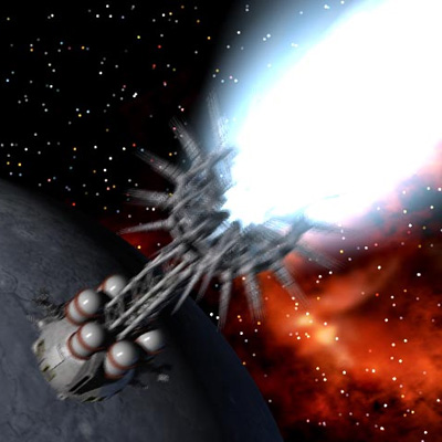

 This little gem is from Aerospace Projects Review Blog. Scott Lowther discovered it in a 1981 Boeing report Controlled Ecological Life Support System: Transportation Analysis.