These are some spacecraft designs that are based on reality. So they appear quite outlandish and undramatic looking. In the next page will appear designs that are fictional, but much more breathtaking. Obviously the spacecraft on this page are all NASA style exploration vehicles, they are not very suited for interplanetary combat (well, most of them at least).
Many of these spacecraft have a table of parameters. You can find the meaning of many of them here. Numbers in black are from the documents. Numbers in yellow have been calculated by me using the document numbers, these might be incorrect.
Nuclear rocket using Indigenous Martian Fuel (NIMF) is from a 1980's Martin Marietta study by Robert Zubrin. The basic idea was to attempt to avoid the tyranny of Every Gram Counts by using in-situ resource utilization for the propellant. So instead of lugging miserly limited amounts of high-performance propellant all the way from Terra, the rocket would make do with unlimited amounts of low-performance propellants available locally on Mars.
There were several vehicles designed: including a supersonic winged craft and a ballistic "hopper". The latter is pictured here. They all featured a single solid core nuclear thermal rocket engine fed by a single propellant tank.
Ideal Specific Impulses of Martian Propellants
Temp
Carbon Dioxide (CO2)
Water (H2O)
Methane (CH4)
CO or N2
Argon
1400 K
162
222
460
162
110
2800 K
283
370
606
253
165
3000 K
310
393
625
264
172
3200 K
337
418
644
274
178
3500 K
381
458
671
289
187
The easiest propellant to manufacture is liquid carbon dioxide. It can be produced from the Martian atmosphere using just high pressure (690 kPa) with no cryogenic cooling needed (a 30 horsepower pump will do, requiring 25 kW, or 80 kilowatt hours per metric ton). The Martian atmosphere is about 95% CO2 so it is not like there is any shortage of the stuff.
Other propellants have superior performance but are much harder to manufacture. Carbon dioxide has enough specific impulse to boost the NIMF from the surface of Mars into low Mars orbit, so the designers figured it was good enough. It also has enough Isp to hop the vehicle from point A to any other point on Mars.
As I mentioned each metric ton of propellant sucked out of the atmosphere takes 80 kilowatt-hours, and the propellant tank holds about 302 metric tons total. About 24,160 kilowatt-hours to fill it. How long it takes to fill the tank depends upon how many kilowatts the power source can feed the pump.
Power can come from the nuclear reactor in the rocket engine, if you make it bi-modal. It would produce about 100 kilowatts of electricity (kWe). Advantage: The report says this will fill the tank in 12 days (my slide rule says it will take 10 days at 100 kWe for 24,160 kWH). It would also require zero mass for the power supply, since the rocket engine has already been accounted for. Disadvantage: is that operating the reactor while the ship is landed with spray deadly radiation all over the landing site. This makes it difficult for the crew to do things like disembark, embark, and linger near the ship.
Power can come from a solar cell array. It can produce about 25 kWe (averaged around the clock to take account of nighttime) Advantage: no radiation Disadvantage: The report does not mention how long it will take to fill the tank but presumably 1.2 as much time as the RTG: 60 days (my slide rule says it will take 40 days at 25 kWe for 24,160 kWH. Why 1.2? 30 kWe / 25 kWe = 1.2). The array is about 3,500 m2 and has a penalty mass of 8.8 metric tons. It also takes three crew members about 2 days to set up and break down, making the total delay about 44 days between flights.
Power can come from an RTG. It can produce about 30 kWe. Advantage: practically no radiation. It has a penalty mass of 4 metric tons, about half of the solar cell array. Unlike the solar cell array it requires no setup or breakdown time. The report says this will fill the tank in 50 days (my slide rule says it will take 34 days at 30 kWe for 24,160 kWH), which is less than the solar cell array. Disadvantage: It has a penalty mass of 4 metric tons as compared to the bi-modal engine. It will take many more days than the bimodal engine.
The paper decided the RTG was the optimal solution.
A reactor temperature of 2800 K (Isp 283) is required to boost the vehicle from the surface of Mars into high orbits (ΔV 5,685 m/s).
But only 1400 K (Isp 162) would be needed for Mars to Mars hops (ΔV 3,254 m/s).
Curved lines are Delta V (ΔV)
Red line = propellant temperature 2800 K
Green Line = mass ratio 7.75
Intersection = ΔV 5,685 m/s
1400 K and 7.75 mass ratio intersect about at the 2000 Km Hop curve
Curved lines are ships with a given mass ratio
Ignore the curve for the NIMF Rocketplane
The Ballistic NIMF at 2800 K is capable of a highly elliptical Mars orbit
As low as 2000 K it can still reach low Mars orbit
Apparently the exhaust velocity (Ve) is assumed to be about 2,587 m/s
From Top to Bottom:
Storage Dome
Flight Deck
Habitation Deck (crew living quarters, supports a crew of three for more than one year)
Mechanical Deck (machinery to liquifly atmospheric carbon dioxide)
Propellant Tank
Nuclear Engine
The nuclear engine has a shadow shield on top composed of steel, boron, and lithium hydride to protect the crew from radiation when the reactor is operating. A secondary toroidal propellant tank surrounds the reactor to protect crew walking on the surface when the reactor is idling. There is a second radiation shield right under the crew, to protect them from backscattered radiation reflected off the ground during landing.
The reactor elements will need special cladding, since when carbon dioxide is heated to high temperatures inside the reactor it will oxidize the heck out of everything it touches. Reactor elements designed for liquid hydrogen propellent won't work, they will rapidly erode and spray powdered glowing radioactive death while the reactor stops producing power and the ship plummets out of the sky.
This is from a report called AFRL-PR-ED-TR-2004-0024 Advanced Propulsion Study (2004). It is a single stage to orbit vehicle using a LANTR for propulsion. They figure it can put about 100 metric tons into orbit at a cost of $150 per kilogram. You can read the details in the report.
Nuclear Ferry
Nuclear Ferry
Propulsion
NTR Solid Core
Propellant
159,000 kg
Dry Mass nuclear stage
32,500 kg
Wet Mass nuclear stage
191,500 kg
Wet Mass total
271,600 kg
Engine Thrust
213,000 N
Number Engines
4
Total Thrust
852,000 N
Length
59.5 m
Diameter
10 m
Lunar Shuttle
Propulsion
Chemical LOX/LH2
Engine Thrust
89,000 N
Number Engines
3
Total Thrust
267,000 N
Crew
2
Passengers
28
Cargo Mass
16,400 kg
Gross Mass
57,100 kg
click for larger image
This is from a 1964 Ling-Temco-Vought, Inc. study for NASA.
The single ferry tank is sized to contain 349,828 pounds of liquid hydrogen and has attached to its after-end, a thrust structure and four fast spectrum metallic-core nuclear reactor engines. Each of the four engines will produce 47,900 pounds of thrust so that with one engine inoperative, the initial thrust-to-weight ratio is 0.24. The dry weight of the nuclear stage is 71,658 pounds, which results in a stage mass fraction of 0.830.
The lunar shuttle, shown in docked position, employs the techique of receiving its propellant by the assembly of prepackaged modules in lunar orbit with the empty module being jettisoned on the lunar surface. The lunar shuttle propulsion system uses LOX-LH2 propellants and is designed around a cluster of three 20,000-pound thrust engines. The lunar shuttle personnel module is of the segmented sphere configuration sized to accommodate a total of 30 men and having all expendables and time-dependent subsystems sufficient for a two-day mission duration.
From Ling-Temco-Vought, Inc. study (1964)
Artwork by Robert McCall
One spaceship that could make the trip is now under study by Ling-Temco-Vought, Inc. for NASA and is show here as it debarks its 28 passengers into a landing craft for the descent to the moon's surface.
The tapered passenger-carrying nose of this ship (below, left) had departed from Earth three days earlier atop a booster. Once in orbit around the Earth, it had then hooked onto a 125-foot-long nuclear-powered ferry (the section carrying the American flag) that carried into the region of the moon.
Having now attained a lunar orbit, the passenger section has swung down 17 feet on long tubular links, alowing a small spherical craft to hook on and load up the passengers for the 100-mile trip down to the moon. In the background at right a similar nuclear ferry also has lowered its passenger section and is about to receive a moon shuttle. Scientists say the passenger section could be used over and over again—for as many as 50 round trips. Because of this reusability, space scientists estimate the eventual cost of maintaining a moon station at only $1 million per man per year.
PARTS Plasma Accelerated Reusable Transport System
P.A.R.T.S. is a 2002 study by the Embry-Riddle Aeronautical University for a reusable Earth-Mars cargo spacecraft utilizing a VASIMR propulsion system powered by an on-board nuclear reactor. The report has lots of juicy details, especially about the reactor. Thanks go out to William Seney for bringing this study to my attention.
RMBLR (Rotating Multi-Megawatt Boiling Liquid-Metal Reactor) "Rambler" System. Fuel: Blocks with coolant channels UN+Moly alloy with Rhenium & hafnium, Primary coolant : Potassium, Reactor outlet temperature:1440K, power conversion: Direct Rankine, Specific Mass: 1-2kg/kWe @ 20 MWe assuming a bubble membrane radiator.
Attitude Thrusters on the Cargo Bay (two not shown)
The idea was to make a workhorse spacecraft for general space transportation needs, but especially a Mars mission. Magnetoplasmadynamic (MPD) and ion drives have very attractive specific impulse/exhaust velocities. But dang, are they ever power hogs. To get a halfway worthwhile thrust will take megawatts of electricity. A solar cell array rated for that much power would be rather huge, a nuclear reactor is indicated. A pity there is not a megawatt class heat radiator designed for freefall.
Then scientists at Battelle Northwest Labs invented the Rotating bubble membrane radiator (RBMR). It works in free fall, it is low mass, and it degrades gracefully if punctured by meteorites. Perfect! It will keep cool an 8.5 megawatt boiling liquid metal fasts reactor. This will supply 6 MWe to the hungry electric engines, and allow the rest of the spacecraft a generous 1.5 megawatts for lifesupport and such.
The concept is called PEGASUS, for PowEr GenerAting System for Use in Space. A real work horse, har har.
The engines are designed for a 510-day burn time, approximately 1,000 day mission duration. The uncrewed vehicle starts in LEO, and slowly but surely rises into GEO under automatic pilot. No crew present during this mission segment because of the long time spent in the deadly Van Allen radiation belt. Once in GEO the crew of three boards the vehicle.
The ship starts out with a payload+structural mass of about 143 metric tons: crew habitat, Mars lander, spacecraft struture.
The Mars mission takes 601 days for the outbound leg, 100 days at Mars, and 268 days for the inbound leg. This consumes 111 metric tons with a 5% reserve. When it returns home its mass will be only 103 tonnes, with 76 tonnes having been left on Mars.
M/Pη is Alpha, or power-plant kilograms per kilowatt. Low is better. Isp is specific impulse of rocket engine. Hi is better. Mp/M is the spacecraft mass ratio, minus 1. Lo is better.
Obviously the lower the Alpha and the higher the Isp, the lower the burn time click for larger image
Three phase alternating current at ten to twenty kilovolts and 1,500 Hertz is fed through a transformer and rectifier into the thruster. The engine assembly is an array of seven thrusters, used one at a time, for a 510-day burn. The lifetime of a thruster is limited by the erosion of the cathode, it is estimated to be 2,000 hours (83 days).
Propellant is injected from the left (arrows marked with "ṁ", meaning "m-dot propellant mass flow.") where it is ionized in the "primary ionization zone" by an electrical discharge between the bell shaped anode and the central rod shaped cathode. The azimuthal (donut-shaped) magnetic field accelerates the propellant in the "Primary Magnetic Acceleration Zone". This is cryptically labeled with J × B, which is physics shorthand for the Lorentz force.
The propellant shoots out the exhaust nozzle with an exhaust velocity between 15,000 to 80,000 meters per second (Isp of 1,530 to 8,160 seconds) in laboratory test rigs. More research has to be done to figure out what the specific impulse will be in practical engines.
Current design has the cathode 3 centimeters in diameter and 10 cm long. The anode has a 12 cm inner diameter. The propellant is argon gas. Potassium metal can also be used, but there is a concern that some of the potassium exhaust could be electrostatically attracted to the rear of the spacecraft, there to plate out over various surfaces and cause short circuits. All die. Oh, the embarrassment.
As a baseline the report assumed use of the J-series 30 cm ion thrusters with mercury propellant, since it has been studied for 15 years. Isp is 4,880 seconds (4,665 needed for Mars mission), thrust 0.51 Newtons (1.20 needed), lifetime 25,000 hours (12,500 needed). The thrust needs to be improved.
Thruster consists of a cathode, an anode, a cylindrical discharge chamber, magnets in the chamber, and a set of closely spaced grids downstream of the cathode and propellant injection. Thrust is created by a propellant ion beam accelerated by the large electric field between the screen and the acceleration grid.
A cathode beam neutralizer makes the ion beam exhaust electrically neutral. Otherwise the engine (and the ship) would develop such a negative electrical charge that the postively charged ion beam would refuse to leave the engine. All die. Oh, the embarrassment.
NUCLEAR ELECTRIC POWER SOURCE
As previously mentioned, the nuclear reactor is called PEGASUS, for PowEr GenerAting System for Use in Space. It is an 8.5 MWe boiling liquid-metal, space-based nuclear power system using a direct Rankine power cycle. It will easily supply the 6 MWe demanded by the power-glutton electrical engines, and have an ample 1.0 to 1.5 MWe left over for life support and mission specific tasks. Other Mars missions have miserly life support power budgets measured in kilowatts. Components are:
Nuclear Reactor: cermet fueld, boiling liquid metal fast reactor. The reactor is 53 cm long and 50 cm in diameter. Peak centerline fuel temperature of 1,300°C with a coolant channel bulk temperature of 1,110°C.
Radiation shield: four-pi contoured man-rated shield. The shield is a composite of lithium oxide, tungsten, and lithium hydride. It is cooled by the reactor inlet coolant.
Power Conversion: axial flow turbine and superconducting alternator. There are two turboalternators, using saturated potassium vapor. Each are capable of producing continuous electric power output of 5.0 megawatts with an output efficiency of 85%. So the total output will be 8.5 megawatts.
Power Conditioning: the requirements will be set by which of the two engine types are used.
Heat Rejection: a rotating bubble membrane radiator
The Rotating bubble membrane radiator is a clever hybrid design with the advantages of both heat pipes and liquid droplet radiators, and amazingly the disadvantages of neither. It has the high surface heat fluxes and operating temperatures of heat pipes, along with the low mass associated with droplet radiators. It operates quite well in freefall. And it can be made resistant to meteorite strikes.
The hot working fluid enters the radiator through the feed section of the feed/return pipe. The hot fluid is ejected from the central spray nozzle in all directions as a combination of droplets and vapor. The hot droplets and gas condense on the spherical radiating surface, transferring the heat to the surface by both convection and radiation. The radiating surface rejects the heat as infrared waves into the depths of space. The external surface can be coated in anti-meteorite armor which is transparent to infrared (probably thermally transparent ceramic fabric).
The spherical surface is rotating on the rotating platform. This give the sphere spin gravity. Ordinarily the cool working fluid on the sphere interior would float around aimlessly in free fall. The spin gravity drags the fluid down into the return pump collection trough at the spin equator. As the fluid travels to the trough it gives up even more heat to the sphere by convection.
The pumps suck up the cool working fluid from the trough through the return piping, and send it back to the reactor through the return section of the feed/return pipe.
Central Spray Nozzle
220 are the return piping
from patient US4789517A "Rotating bubble membrane radiator"
Central Spray Nozzle interior
240 is the feed, which enters the sphere through pipes 250. The hot working fluid fills the sphere, and exits by the central spray nozzles 210.
230 is the return, fed by return piping 80
from patient US4789517A "Rotating bubble membrane radiator"
Rotation Platform, Attachment Boom, and Feed/Return pipe
Section 30 is stationary, as are stationary feed (340) and return (330). Stationary feed/return are joined to the rotating feed/return (240/230) by rotating fluid coupling 350
260 is the electric motor and gearing which spins the platform
from patient US4789517A "Rotating bubble membrane radiator"
The original PEGASUS drive spacecraft was powerful enough to perform fast piloted missions to Mars (400 days Terra-Mars), with an alpha of about 7.5 kg/kW. It used a 10 megawatt electrical power system (10 MWe). When the Department of Energy declassified the data on the new Rotating Multimegawatt Boiling Liquid Metal (RMBLR) power system (20 MWe), the report authors realized this would allow the creation of a second-generation PEGASUS drive with an alpha less than 2.5 kg/kW. This would make the trip time even shorter.
What's more, the extra electricity could also permit fancy extras like laser power beaming to supply electricity to the Mars exploration crew on the surface.
click for larger image
click for larger image
The report figures that by using the new 20 MWe RMBLR, one could design an uncrewed Terra-Mars cargo vehicle with a total mass in LEO of 400 metric tons that could deliver a payload of 193 metric tons of supplies and hardware to low Mars orbit in 282 days flat.
If you add a laser power transmitter to the PEGASUS Drive, and include a laser power receiver in the surface payload, it could transmit 2 MWe to the surface. As long as the reactor can last seven to ten years it will take for the crewed mission to arrive, the surface explorers will have plenty of juice available for the exploration equipment. The access to megawatts of energy instead of the customary measly kilowatts will vastly enhance and expand the mission options possible for the surface exploration.
Upon arrival the cargo vessel will place the payload in a Mars parking orbit, then the unloaded vessel will then put itself into a Mars synchronous orbit above the future crewed landing site. While waiting for the crewed mission to show up, the vessel can send laser power to the payload in orbit for housekeeping energy.
Mission Profiles
The optimal crewed Mars mission is the so-called "Split-sprint" mission. This is when you send all the heavy equipment and other payload on an uncrewed relatively slow spacecraft. Once it is confirmed as successfully arriving at low Mars orbit (and only if), you then dispatch the crewed mission in a relatively fast spacecraft (fast, to reduce life support consumables mass and radiation exposure).
The crewed sprint ship would have a total mass in LEO of 303 metric tons and an alpha of 7.3 kg/kWe. Outbound leg of 165 days, stay in Mars orbit (and surface exploration) of 30 days, and a return leg of 217 days. Total crewed mission duration of 412 days. When the ship approaches Terra, the crew abandons it and uses an Earth Crew Capture Vehicle (ECCV) to aerobrake to a Terra landing.
The laser power option for the cargo vessel sort of precludes allowing the ship to return to Terra. However, in the unhappy event of the crewed ship becoming disabled, there will be some way of reconfiguring the two spacecraft into an backup return vehicle. Probably by jettisoning the crewed ship's propulsion bus and attaching the bus from the cargo ship. The backup return vehicle will take 345 days to return to Terra instead of the planned 217 due to the different engine characteristics, so the life support system will need an extra 128 days of consumables.
Propulsion System
Electromagnetic and electrostatic propulsion have not been taken seriously, because they are power hogs. But they become attractive with the advent of low-mass megawatt-level nuclear power reactors. Once you get past the power requirements, the systems are very simple, compact, rugged, and have very high specific impulse/exhaust velocity.
MPD Thruster System
Again this spacecraft uses Magnetoplasmadynamic engines. Since these have a lifetime of only 2,000 hours (83 days) due to severe cathode erosion, it has an array of seven engines used once at a time in order to perform the 12,240 hour (510 day) mission burn time.
The central cathode is 3 centimeters in diameter and 10 centimeters long. The anode has a 12 cm inside diameter. The most massive part is the anode heat removal system.
Electrical Power Source
PEGASUS is a 10 MWe boiling liquid-metal reactor power system. It is composed of five subsystems: a cermet-fueled boiling liquid metal fast reactor; a shadow shield; three radial flow Ljungström turbines, each driving a counterrotating superconducting alternator; a power conditioning subsystem; and a heat radiator.
REACTOR: this is a fast reactor using a boiling alkali metal coolant and cermet fuel. It uses the Rotating Multimegawatt Boiling Liquid Metal (RMBLR) power system. The cermet fuel (UN/moly) is composed of a refractory-metal alloy (Mo-7Re-3Hf) matrix with highly enriched uranium nitride (UN) fuel. For details on why this alloy was chosen, refer to the report.
POWER CONVERSION: many conversion systems were survey before one was found that could operate in the space environment. The Ljungström turbine turned out to be ideal. For details see the report. This is
attached to a counterrotating superconducting alternator to generate electrical power. The overall power conversion subsystem is expected to have a specific weight of 0.5 kg/kW and an efficiency of 98%.
Pilgrim Observer
RocketCat sez
Another blast from the past! Rocket fans who built this plastic model back in the 1970's agree it makes the needle of their Nostalgia-meter slam over and wrap itself around the end peg. But what is more astonishing is the real-world roots of the blasted thing. Sure it has a couple of design problems, but it makes far more scientific sense than 99% of the other plastic models.
Pilgrim Observer
Propulsion
NERVA 2b
Propulsion
Uprated J2 chemical
NERVA Specific Impulse
850 s
J2 Specific Impulse
~450 s
NERVA Exhaust Velocity
8,300 m/s
J2 Exhaust Velocity
4,400 m/s
Wet Mass
? kg
Dry Mass
? kg
Mass Ratio
?
ΔV
? m/s
NERVA Mass Flow
13 kg/s
J2 Mass Flow
25 kg/s
NERVA Thrust
110,000 newtons
J2 Thrust
110,000 newtons
Initial Acceleration
? g
Payload
? kg
Length
30 m + boom
Diameter
46 m
The Pilgrim Observer was a plastic model kit issued by MPC back in 1970 (MPC model #9001) designed by G. Harry Stine. Many of us oldster have fond memories of the kit. It was startlingly scientifically accurate, especially compared its contemporaries (ST:TOS Starship Enterprise, ST:TOS Klingon Battlecruiser, Galactic Cruiser Leif Ericson).
The model kit included a supplemental booklet just full of all sorts of fascinating details. NERVA engine design, mission plan, all sorts of goodies with the conspicuous absence of the mass ratio and the total delta-V.
The kit has been recently re-issued, and those interested in realistic spacecraft design could learn a lot by building one. If you do, please look into the metal photoetched add-on kit, and alternate decals (went out of business in 2014). Round 2 Models (the company who re-issued the kit) have some detailed kit building instructions here.
The Pilgrim makes a cameo appearance in Jerry Pournelle's short story "Tinker", in the role of the Boostship Agamemnon, and in Allen Steele's short story "The Weight" as the Medici Explorer.
Original model kit
Recent re-issue
The design is interesting, and has a lot of innovative elements. For one, it uses a species of gimbaled centrifuge to deal with the artificial gravity problem. It also uses distance to augment its radiation shielding, in order to save on mass and increase payload. This is done by mounting the NERVA solid core nuclear rocket on a telescoping boom.
One major flaw with the Pilgrim's design is the fact that one of the three spinning arms is the power reactor. This means that all the ship's power supply has to be conducted through a titanic slip-ring, since there can be no solid connection between the spin part and the stationary part. Another flaw is if you are going to all the trouble to put the NERVA reactor on a boom to get the radiation far away from the crew, why would you put the radioactive power reactors on an arm right next to the crew?
Anyway, the Pilgrim is an orbit-to-orbit spacecraft that is incapable of landing on a planet. It has a ten man crew (four crew and six scientists), and has enough life support endurance to keep them alive for five years. It could also be used as a space station, in LEO, GEO, or lunar orbit. In launch configuration the NERVA boom is retracted and the spinning arms are locked down. In this configuration it is 100 feet long and 33 feet wide, which fits on top of the second stage of a Saturn V booster. A disposable shroud is placed over the top of the spacecraft to make it more aerodynamic during launch.
Level
Gravity
Level 6
0.05g
Level 5
0.06g
Level 4
0.07g
Level 3
0.08g
Level 2
0.09g
Level 1
0.10g
After launch, the shroud is jettisoned, the spinning arms deploy, and the NERVA engine's boom telescopes out. The spinning arm array has a diameter of 150 feet. The arms will rotate at a rate of two revolutions per minute (safely below the 3 RPM nausea limit). This will produce about one-tenth Earth gravity at the tips of the arms (Level 1), which fades to zero gravity at the rotation axis. Not much but better than nothing. The spherical center section does not spin, a special transfer cabin is used to move between the spin and non-spin sections.
One arm is the crew quarters, one is a hydroponic garden for the closed ecological life support system, and the third is a stack of advanced Space Nuclear Auxiliary Power (SNAP) reactors using Brayton cycle nuclear power units.
Under thrust, the arms must be angled to align with the vector sum of the centripetal acceleration and the thrust acceleration. Otherwise the direction of "down" will appear to be towards the rear-wall/floor corner of the cabin, and the rooom will feel like it is tipped on its corner. Artwork by Zubie of the blog Constant Variations.
Control center
Astrotug
The center section is divided into the Main Control Center at the top and the Service Section at the bottom. The very top of the Control Center has the large telescope, radar, and other sensors. By virtue of being mounted on the non-spin section, the astronomers and astrogators can make their observations without having to cope with all the stars spinning around. Also mounted here is the antenna farm for communications and telemetry.
The Pilgrim carries two auxiliary vehicles: a modified Apollo command and service module, and a one-man astrotug similar to the worker pods seen in the movie 2001 A Space Odyssey. They mate with Universal Docking Adaptors on the non-spin section.
The chemical propulsion system consists of three up-rated J-2 rocket engines with a thrust of 250,000 lbs, fueled by liquid hydrogen and liquid oxygen.
The nuclear thermal propulsion system consists of one solid-core NERVA 2B, using liquid hydrogen as propellant. The NERVA has a specific impulse of 850 seconds, a thrust of 250,000 pounds, and an engine mass of 35,000 pounds (the fact that both the J-2 and the NERVA have identical thrust makes me wonder if that is a misprint). It uses a de Laval type convergent-divergent rocket nozzle. The reactor core has a temperature of 4500°F. The core of the reactor is encased in a beryllium neutron reflector shell. Inside the reflector and surrounding the reactor core are twelve control rods. Each rod is composed of beryllium with a boron neutron absorber plate along one side. By rotating the control rods, the amount of neutrons reflected or absorbed can be controlled, and thus control the fission chain reaction in the reactor core.
There is a dome shaped shadow shield on top of the NERVA to protect the crew from radiation. In addition, the NERVA is on a long boom, adding the inverse square law to reduce the amount of radiation. And finally, the cosmic ray shielding around the crew quarters provides even more protection.
Various attitude control and ullage rockets are located at strategic spots, they are fueled by hypergolic propellants.
The mission will start in June of 1979. Mission is an Earth-Mars-Venus-Earth swing-by. It will have a mission duration of 710 days, as compared to the 971 days required for a simple Mars orbiting round trip. This is done with clever gravitational sling-shots, and use of the NERVA 2B.
Mission starts with an orbital plane change to a 200 nautical mile circular Earth orbit inclined 23°27' (i.e., co-planar with the ecliptic). Transarean insertion burn is made with the three J-2 chemical engines (D+0). At this point the Pilgrim 1 becomes the Pilgrim-Observer space vehicle. It will coast for 227 days. Then it will perform a retrograde burn with the NERVA to achieve a circumarean orbit (Mars orbit) with a periapsis of 500 nautical miles and a high point of 5,800 nautical miles (D+227).
The Pilgrim-Observer will spend 48 days in Martian orbit (including several close approaches to Phobos). Then the NERVA will thrust into a transvenerian trajectory (D+275). It will coast for 246 days, including a close approach and fly-by of the asteroid Eros occurring 145 days after transvenerian burn (D+320).
The NERVA will burn into a circumvenarian orbit of of 500 nautical miles (D+521). It will spend 55 days studying Venus.
The NERVA will thrust into a transearth injection (D+576). It will coast for 140 days. Upon Earth approach, it will burn into a 200 nautical mile Earth orbit (D+710). The crew will be out shipped by a shuttle craft following extensive debriefing.
I did some back of the envelope calculations, and the numbers look fishy to me. An Earth-Mars Hohmann and Mars capture orbit will take a delta V of about 5,200 m/s. This is done with the J-2 chemical engine, and will require a mass ratio of 3.3. That is not a problem.
The problem comes with the NERVA burns. The Mars-Venus burn and the Venus-Earth burns have a total of about 14,800 k/s. With a NERVA exhaust velocity of 8,300 m/s, this implies a mass ratio of 5.9. I'm sorry but without staging you are going to be lucky to get a mass ratio above 4.0.
The plastic model kit is allegedly 1:100 scale according to the kit instructions. However, expert model builders who did measurements figured out that various parts are clumsily in different scales. The "arms folded mode" diameter is supposed to be 33 feet, to fit on top of a Saturn V, that is 1:127 scale. The rotating arms and the Apollo M are more like 1:144 to 1:200 scale. At 1:100 the arms have a deck spacing of a cramped 5 feet, the passage connecting the arm to the ship proper is only 2.5 feet in diameter, and the command module on the Apollo M is 20% smaller than the real Apollo CM. So the scale of the plastic model kit is a mess.
BoostShip Agamemnon
The Agamemnon is basically the Pilgrim Observer with the NERVA solid core NTR swapped out for an ion drive powered by a deuterium fusion reactor.
A Step Farther Out
IBS Agamemnon
Total ΔV
280,000 m/s
Specific Power
39 kW/kg (39,000 W/kg)
Thrust Power
1.1 terawatts
Exhaust velocity
220,000 m/s
Thrust
10,000,000 n
Wet Mass
100,000 mt
Dry Mass
28,000 mt
Mass Ratio
3.57
Ship Mass
8,000 mt
Cargo Mass
20,000 mt
Length
400 m
Length spin arm
100 m
T/W >1.0
no
IBS Agamemnon (Interplanetary Boost Ship) masses 100,000 tons as she leaves Earth orbit. She carries up to 2000 passengers with their life support requirements. Not many of these will be going first-class, though; many will be colonists, or even convicts, headed out steerage under primitive conditions.
Her destination is Pallas, which at the moment is 4 AU from Earth, and she carries 20,000 tons of cargo, mostly finished goods, tools, and other high-value items they don't make out in the Belt yet. Her cargo and passengers were sent up to Earth orbit by laser-launchers; Agamemnon will never set down on anything larger than an asteroid.
She boosts out at 10 cm/sec2, 1/100 gravity, for about 15 days, at which time she's reached about 140 km/second. Now she'll coast for 40 days, then decelerate for another 15. When she arrives at Pallas she'll mass 28,000 tons. The rest has been burned off as fuel and reaction mass. It's a respectable payload, even so.
The reaction mass must be metallic, and it ought to have a reasonably low boiling point. Cadmium, for example, would do nicely. Present-day ion systems want cesium, but that's a rare metal—liquid, like mercury—and unlikely to be found among the asteroids, or cheap enough to use as fuel from Earth.
In a pinch I suppose she could use iron for reaction mass. There's certainly plenty of that in the Belt. But iron boils at high temperatures, and running iron vapor through them would probably make an unholy mess out of the ionizing screens. The screens would have to be made of something that won't melt at iron vapor temperatures. Better, then, to use cadmium if you can get it.
The fuel would be hydrogen, or, more likely, deuterium, which they'll call "dee." Dee is "heavy hydrogen," in that it has an extra neutron, and seems to work better for fusion. We can assume that it's available in tens-of-ton quantities in the asteroids. After all, there should be water ice out there, and we've got plenty of power to melt it and take out hydrogen, then separate out the dee.
(ed note: 1,100 gigawatts requires burning about 0.014 kilograms of deuterium per second. For 30 days total burn time this will require about 36 metric tons of deuterium.)
If it turns out there's no dee in the asteroids it's not a disaster. Shipping dee will become one of the businesses for interplanetary supertankers.
From Life Among the Asteroids by Jerry Pournelle, collected in A Step Farther Out (1975)
Tinker
Artwork by Rick Sternbach (1975). Click for larger image
MAYDAY MAYDAY MAYDAY. THIS IS PEGASUS LINES BOOSTSHIP AGAMEMNON OUTBOUND EARTH TO PALLAS.
OUR MAIN ENGINES ARE DISABLED. I SAY AGAIN, MAIN ENGINES DISABLED. OUR VELOCITY RELATIVE TO SOL IS ONE FOUR ZERO KILOMETERS PER SECOND, I SAY AGAIN, ONE HUNDRED FORTY KILOMETERS PER SECOND. AUXILIARY POWER IS FAILING. MAIN ENGINES CANNOT BE REPAIRED. PRESENT SHIP MASS IS 54,000 TONS. SEVENTEEN HUNDRED PASSENGERS ABOARD. MAYDAY MAYDAY MAYDAY.
The other screen lit, giving us what the Register knew about Agamemnon. It didn't look good. She was an enormous old cargo-passenger ship, over thirty years old—and out here that's old indeed. She'd been built for a useful life of half that, and sold off to Pegasus Lines when P&L decided she wasn't safe.
Her auxiliary power was furnished by a plutonium pile. If something went wrong with it, there was no way to repair it in space. Without auxiliary power, the life-support systems couldn't function.
I switched the comm system to Record. "Agamemnon, this is cargo tug Slingshot. I have your Mayday. Intercept is possible, but I cannot carry sufficient fuel and mass to decelerate your ship. I must vampire your dee and mass, I say again, we must transfer your fuel and reaction mass to my ship.
"We have no facilities for taking your passengers aboard. We will attempt to take your ship in tow and decelerate using your deuterium and reaction mass. Our engines are modified General Electric Model five-niner ion-fusion. Preparations for coming to your assistance are under way. Suggest your crew begin preparations for fuel transfer. Over."
The Register didn't give anywhere near enough data about Agamemnon. I could see from the recognition pix that she carried her reaction mass in strap-ons alongside the main hull, rather than in detachable pods right forward the way Slinger does. That meant we might have to transfer the whole lot before we could start deceleration.
She had been built as a general-purpose ship, so her hull structure forward was beefy enough to take the thrust of a cargo pod—but how much thrust? If we were going to get her down, we'd have to push like hell on her bows, and there was no way to tell if they were strong enough to take it.
The refinery crew had built up fuel pods for Slinger before, so they knew what I needed, but they'd never made one that had to stand up to a full fifth of a gee. A couple of centimeters is hefty acceleration when you boost big cargo, but we'd have to go out at a hundred times that.
They launched the big fuel pod with strap-on solids, just enough thrust to get it away from the rock so I could catch it and lock on. We had hours to spare, and I took my time matching velocities. Then Hal and I went outside to make sure everything was connected right.
Slingshot is basically a strongly built hollow tube with engines at one end and clamps at the other. The cabins are rings around the outside of the tube. We also carry some deuterium and reaction mass strapped on to the main hull, but for big jobs there's not nearly enough room there. Instead, we build a special fuel pod that straps onto the bow. The reaction mass can be lowered through the central tube when we're boosting.
Boost cargo goes on forward of the fuel pod. This time we didn't have any going out, but when we caught up to Agamemnon she'd ride there, no different from any other cargo capsule. That was the plan, anyway. Taking another ship in tow isn't precisely common out here.
Everything matched up. Deuterium lines, and the elevator system for handling the mass and getting it into the boiling pots aft; it all fit.
Ship's engines are complicated things. First you take deuterium pellets and zap them with a big laser. The dee fuses to helium. Now you've got far too much hot gas at far too high a temperature, so it goes into an MHD system that cools it and turns the energy into electricity.
Some of that powers the lasers to zap more dee. The rest powers the ion drive system. Take a metal, preferably something with a low boiling point like cesium, but since that's rare out here cadmium generally has to do. Boil it to a vapor. Put the vapor through ionizing screens that you keep charged with power from the fusion system.
Squirt the charged vapor through more charged plates to accelerate it, and you've got a drive. You've also got a charge on your ship, so you need an electron gun to get rid of that.
There are only about nine hundred things to go wrong with the system. Superconductors for the magnetic fields and charge plates: those take cryogenic systems, and those have auxiliary systems to keep them going. Nothing's simple, and nothing's small, so out of Slingshot's sixteen hundred metric tons, well over a thousand tons is engine.
Now you know why there aren't any space yachts flitting around out here. Slinger's one of the smallest ships in commission, and she's bloody big. If Jan and I hadn't happened to hit lucky by being the only possible buyers for a couple of wrecks, and hadn't had friends at Barclay's who thought we might make a go of it, we'd never have owned our own ship.
When I tell people about the engines, they don't ask what we do aboard Slinger when we're on long passages, but they're only partly right. You can't do anything to an engine while it's on. It either works or it doesn't, and all you have to do with it is see it gets fed.
It's when the damned things are shut down that the work starts, and that takes so much time that you make sure you've done everything else in the ship when you can't work on the engines. There's a lot of maintenance, as you might guess when you think that we've got to make everything we need, from air to zweiback. Living in a ship makes you appreciate planets.
Space operations go smooth, or generally they don't go at all.
When we were fifty kilometers behind, I cut the engines to minimum power. I didn't dare shut them down entirely. The fusion power system has no difficulty with restarts, but the ion screens are fouled if they're cooled. Unless they're cleaned or replaced we can lose as much as half our thrust—and we were going to need every dyne.
His face didn't change. "Experienced cadets, eh? Well, we'd best be down to it. Mr. Haply will show you what we've been able to accomplish."
They'd done quite a lot. There was a lot of expensive alloy bar-stock in the cargo, and somehow they'd got a good bit of it forward and used it to brace up the bows of the ship so she could take the thrust. "Haven't been able to weld it properly, though," Haply said. He was a young third engineer, not too long from being a cadet himself. "We don't have enough power to do welding and run the life support too."
Agamemnon's image was a blur on the screen across from my desk. It looked like a gigantic hydra, or a bullwhip with three short lashes standing out from the handle. The three arms rotated slowly. I pointed to it. "Still got spin on her."
"Yes." Ewert-James was grim. "We've been running the ship with that power. Spin her up with attitude jets and take power off the flywheel motor as she slows down."
I was impressed. Spin is usually given by running a big flywheel with an electric motor. Since any motor is a generator, Ewert-James's people had found a novel way to get some auxiliary power for life-support systems.
Agamemnon didn't look much like Slingshot. We'd closed to a quarter of a klick, and steadily drew ahead of her; when we were past her, we'd turn over and decelerate, dropping behind so that we could do the whole cycle over again.
Some features were the same, of course. The engines were not much larger than Slingshot's and looked much the same, a big cylinder covered over with tankage and coils, acceleration outports at the aft end. A smaller tube ran from the engines forward, but you couldn't see all of it because big rounded reaction mass canisters covered part of it.
Up forward the arms grew out of another cylinder. They jutted out at equal angles around the hull, three big arms to contain passenger decks and auxiliary systems. The arms could be folded in between the reaction mass canisters, and would be when we started boosting. All told she was over four hundred meters long, and with the hundred-meter arms thrust out she looked like a monstrous hydra slowly spinning in space.
The fuel transfer was tough. We couldn't just come alongside and winch the stuff over. At first we caught it on the fly: Agamemnon's crew would fling out hundred-ton canisters, then use the attitude jets to boost away from them, not far, but just enough to stand clear.
Then I caught them with the bow pod. It wasn't easy. You don't need much closing velocity with a hundred tons before you've got a hell of a lot of energy to worry about. Weightless doesn't mean massless.
We could only transfer about four hundred tons an hour that way. After the first ten-hour stretch I decided it wouldn't work. There were just too many ways for things to go wrong.
"Get rigged for tow," I told Captain Ewert-James. "Once we're hooked up I can feed you power, so you don't have to do that crazy stunt with the spin. I'll start boost at about a tenth of a centimeter. It'll keep the screens hot, and we can winch the fuel pods down."
He was ready to agree. I think watching me try to catch those fuel canisters, knowing that if I made a mistake his ship was headed for Saturn and beyond, was giving him ulcers.
First he spun her hard to build up power, then slowed the spin to nothing. The long arms folded alongside, so that Agamemnon took on a trim shape. Meanwhile I worked around in front of her, turned over and boosted in the direction we were traveling, and turned again.
The dopplers worked fine for a change. We hardly felt the jolt as Agamemnon settled nose to nose with us. Her crewmen came out to work the clamps and string lines across to carry power. We were linked, and the rest of the trip was nothing but hard work.
We could still transfer no more than four hundred tons an hour, meaning bloody hard work to get the whole twenty-five thousand tons into Slinger's fuel pod, but at least it was all downhill. Each canister was lowered by winch, then swung into our own fuel-handling system, where Singer's winches took over. Cadmium's heavy: a cube about two meters on a side holds a hundred tons of the stuff. It wasn't big, and it didn't weigh much in a tenth of a centimeter, but you don't drop the stuff either.
Finally it was finished, and we could start maximum boost: a whole ten centimeters, about a hundredth of a gee. That may not sound like much, but think of the mass involved. Slinger's sixteen hundred tons were nothing, but there was Agamemnon too. I worried about the bracing Ewert-James had put in the bows, but nothing happened.
Three hundred hours later we were down at Pallasport.
The Wayfarer is basically a stock Pilgrim Observer, all the way down to the NERVA engine. Except that the arms do not extend and rotate for artificial gravity.
Exiles To Glory
Their first impression was of a bundle of huge cigars. Those were the big fuel tanks almost a hundred meters long. They were so large that they dwarfed the rest of the ship, and ran the entire length of midsection. Behind the "cigars" was a solid ring that held three rocket motors. Then at the end of a spine as long as the main body of the ship was the nuclear reactor and another rocket motor.
This was the real drive. The three chemical rockets were only for steering and close maneuvering. Wayfarer's power came from her atomic pile. The cigar-shaped tanks held hydrogen, which was pumped back to the reactor where it was heated up and spewed out through the rear nozzle. A ring of heavy shielding just forward of the reactor kept the pile's radiation from getting to the crew compartment. The rest of the pile wasn't shielded at all.
Despite the large size of the ship, the crew and cargo sections seemed quite small. There were some structures reaching back from the forward ring where the control room was. Two of those were passenger quarters. The other was another nuclear power unit to make electricity to run the environmental control equipment, furnish light for the plants, power to reprocess air, and all the other things the ship and passengers and crew would need. There was a big telescope and a number of radar antennae on the forward section.
The scooter pilot was careful not to get near the reactor in the ship's "stinger."
The ship had been designed for sixty passengers. She carried twice that number plus eight crew.
The internal space was constructed in a series of circular decks. Each deck had an eight-foot hole in its center, so that from the forward end, just aft of the separately enclosed control cabin, Kevin could look all the way aft to the stern bulkhead. Although there was a long and rather flimsy-appearing steel ladder stretching from aft to forward bulkhead, no one used it.
"F deck," the crewman said "A deck is the bridge. B is the wardroom. C, D, and E are the three aft of that. E happens to be the recreation and environmental control. Yours is the one beyond that. They're marked."
Finally he reached F deck, which he found to be sectioned into slice-of-pie compartments arranged in a ring around the central well, fifteen of them in all. He found the one marked "12" and went in.
His "stateroom" was partitioned off with a flexible, bright blue material that Kevin thought was probably nylon. The door was of the same stuff and tied off
with strings. It didn't provide much privacy.
Inside the cramped quarters were facilities for two people. There were no bunks, but two blanket rolls strapped against the bulkhead indicated the sleeping arrangements. It made sense, Kevin thought. You didn't need soft mattresses in space. "Sleeping on a cloud" was literally true here. You needed straps to keep you from drifting away, but that was all.
One viewscreen with control console, a small worktable, and two lockers about the size of large briefcases completed the furnishings.
The incident reminded Kevin that he was in free fall, and his stomach didn't like it much. He gulped hard. "I'll be glad when we're under way," he said. "It won't last long, but it will be nice to have some weight again. Even for a day or so."
Norsedal frowned and rolled his eyes upward for a moment. "Not that long, I'm afraid," he said. "Let's see, total velocity change of about five kilometers a second, at a tenth of gravity acceleration—five thousand seconds." He took a pocket computer off his belt and punched numbers. "An hour and a half. Then we're back in zero-gravity."
Weight felt strange. The ship boosted at about ten percent of Earth's gravity, but Kevin found that quite enough. All over the ship loose objects fell to the decks.
Ninety minutes later the acceleration ended. Wayfarer was now in a long elliptical orbit that would cross the orbit of Ceres. Left to itself, the ship would go on past, more than halfway to Jupiter, before the Sun's gravity would finally turn it back to complete the ellipse and return it to its starting point. In order to land on Ceres, the ship would have to boost again when it got out to the orbit of the asteroid.
There would also be minor course-correction maneuvers during the trip, but except for those the ship's nuclear-pile engine wouldn't be started up until they arrived at Ceres's orbit. Then the ship would accelerate to catch up with the asteroid. That wouldn't happen for nine months.
The heart of the system was a series of large transparent tanks filled with green water and tropical fish. Once Wayfarer was under way the crew erected large mirrors outside the hull. The mirrors collected sunlight and focused it through Plexiglas viewports onto the algae tanks. A ventilation system brought the ship's air into the tanks as a stream of bubbles. Other pumping systems collected sewage and forced it into chemical processors; the output was treated sewage that went to the algae tanks as fertilizer.
Wayfarer had two airlocks. One was right in the bows, a large docking port that allowed smaller space capsules to link up with the ship, and could also be used to link with an airtight corridor connecting the ship with the Ceres spaceport, or even with another ship. The other was a smaller personnel lock on the side of the hull just aft of the bows. Kevin and Ellen went out that way. There was a small ladder leading forward. It wasn't needed as a ladder, but it provided handholds.
The telescope was large, over a foot in diameter, with flexible seals that let it pass through the ship's hull and into the control bridge.
The ship's engines started. There was no sound and no flame. Hydrogen was pumped from the tanks and into the nuclear pile on its sting at the end of the ship. The nuclear reactor heated the hydrogen and forced it back through nozzles. The ship drove forward at a tenth of a gravity.
From Exiles to Glory by Jerry Pournelle (1977)
Medici Explorer
The Weight
This is NOT the Medici Explorer
but it is
[1] a sketch by Allen Steele
[2] from a story in the same anthology as "The Weight"
[3] has a very similar layout
Medici Explorer locations mapped onto the Pilgrim Explorer
(ed note: the Medici Explorer is basically the Pilgrim Observer with the NERVA solid core NTR swapped out for a gas-core NTR)
The Medici Explorer was fifty-six meters in length, from the gunmetal-grey nozzle of its primary engine to the grove of antennae and telescopes mounted on its barrel-shaped hub module; at the tips of its three arms—which were not yet rotating—the spacecraft was about forty-six meters in diameter. Pale blue moonlight reflected dully from the tube-shaped hydrogen, oxygen, and water tanks clustered in tandem rows between the hub and the broad, round radiation shield at the stern. Extended on a slender boom aft of the shield, behind the three gimbal-mounted maneuvering engines, was the gas-core nuclear engine, held at safe distance from the crew compartments at the forward end of the vessel. Although the reactor stack in Arm Three was much closer to the hub, it was heavily shielded and could not harm the crew when it was in operation.
The Medici Explorer was already awake and thriving. Two days earlier, it had departed from Highgate, the lunar-orbit spacedock where it had been docked since the completion of its last voyage six months ago. During the interim, while its crew rested at Descartes City and the precious cargo of Jovian helium-3 was unloaded from the freighters and transported to Earth, the Medici Explorer had undergone the routine repairs necessary before it could make its next trip to Jupiter. Now, at long last, the giant spacecraft had been towed by tugs to a higher orbit where it was reunited with its convoy.
The shuttle made its final approach toward the vessel’s primary docking collar on the hub module. On the opposite side of the docking collar, anchored to a truss which ran through a narrow bay between the outboard tanks, was the Marius, a smaller spacecraft used for landings. The fact that the ship’s boat was docked with the larger vessel was evidence that the Medici Explorer’s crew had returned from shore leave; more proof could be seen from the lights which glowed from the square windows of Arm One and Arm Two (in model kit, Arm 1 windows are square, Arm 2 windows in hydroponics are circular).
Red and blue navigational beacons arrayed along the superstructure illuminated more details: an open service panel on the hub where a robot was making last-minute repairs; a hardsuited space worker checking for micrometeorite damage to the hull; the round emblem of Consolidated Space Industries, the consortium which owned the vessel, painted on the side of the hub. Then the shuttle slowly yawed starboard, exposing its airlock hatch to the docking collar, and the Medici Explorer drifted away from its windows.
So on and so forth, barely pausing for breath, as we dropped down the hub’s access shaft to the carousel which connects the hub to the ship’s three arms. Since the arms were not presently rotating, we didn’t need to make the tricky maneuver of reorienting ourselves until the appropriate hatchway swung past us. The carousel’s hatches were aligned with their appropriate arms, so all we had to do was squirm through the upward-bending corridor—passing the sealed tiger-striped hatch which led to the reactor stack in Arm Three—until we reached the open hatch marked Arm 1.
arm central shaft
The arm’s central shaft resembled a deep well, fifteen meters straight down to the bottom. Although I consciously knew that I couldn’t fall in zero-gee, I instinctively rebelled at the thought of throwing myself into a neck-breaking plummet. While I paused at the edge of the hatch, still visually disoriented by the distance, Young Bill dove headfirst through the hatch, scarcely grabbing the rungs of the ladder which led down the blue-carpeted wall of the shaft. I shut my eyes for a moment, fighting a surge of nausea, then I eased myself feet-first into the shaft, carefully taking each rung a step at a time.
There were six levels in Arm One, each accessed by the long ladder. Still babbling happily about rain forests and South American Indian tribes, Young Bill led me past Level 1-A (the infirmary and life sciences lab) Level 1-B (the Smith-Tate residence), Level 1-C (Smith-Makepeace) and Level 1-D (Smith-Tanaka). The hatches to each deck were shut, but as we glided past Level 1-D, its hatch opened and a preadolescent boy recklessly rushed out into the shaft and almost collided with Young Bill.
Young Bill shut the hatch, then led me down one more level to Deck 1-E, the passenger quarters.
He opened the hatch to Deck 1-E and pulled himself inside, hauling my duffel bag behind him. The deck was divided into four passenger staterooms, along with a common bathroom; not surprisingly, it was marked Head, retaining the old nautical term. The small compartment Bill led me to had its own foldaway bed, desk, data terminal and screen, along with a wide square window through which I could see the Moon.
Don’t bother making yourself at home,” he said as he stowed my duffel bag in a closet. “After we launch, you won’t see this place again for nine months.”
I nodded. “The other passengers… they’re already in hibernation?”
Yep. I helped Uncle Yoshi dope ’em up a few hours ago. They’re zombified already. You’ll be joining them after we—”
Although there are three decks to the ship’s hydroponics bay (in Arm 2), one can enter the section only through the hatch at the top level; the idea is to contain the humid environment of Hydroponics as much as possible.
Control center
note observation blister on left, captain's station upper center
The Medici Explorer’s command center was shaped like the inside of a Chinese wok. Located on the top deck of the hub, Deck H-1 was the largest single compartment in the vessel: about fifteen meters in diameter, the bridge had a sloping, dome-shaped ceiling above a shallow, tiered pit. Two observation blisters, each containing an optical telescope, were mounted in the ceiling at opposite ends of the pit; between them were myriad computer flat-screens and holographic displays, positioned above the duty stations arranged around the circumference of the pit. In the center of the bridge, at the bottom of the pit between and slightly below the duty stations, was the captain’s station, a wingback chair surrounded by wraparound consoles. On one side of the bridge was the hatch leading to the hub’s access tunnel; on the opposite side was a small alcove, a rest area furnished with three chairs and a small galley.
It may sound claustrophobic and technocratic, but the bridge was actually quite spacious and comfortable. The floors were carpeted, allowing one to comfortably walk on them provided that one was wearing stikshoes, and the holoscreens provided a variety of scenes from outboard cameras as well as the main telescope, giving the illusion of cathedral windows looking out upon the grand cosmos.
“I’ll leave you to Wendy’s tender mercy,” Young Bill said as he gave me a slap on the shoulder. He then pushed off the floor, floating upward to grab a ceiling rung. “Captain, may I watch the launch from the blister, please?”
It didn’t seem as if Montrose could hear anything from within his thick VR helmet, but the captain circled a thumb and index finger, giving him the OK sign. “Thank you, sir,” Young Bill said, then worked his way along the ceiling rungs, hand over hand, until he reached the observation blister between the engineering and communications stations. With one free hand he tapped the control panel next to the hemispherical bulge; the blister’s hatch slid open, briefly revealing a tiny compartment with a single armchair mounted in front of a binocular eyepiece. Young Bill glided feet-first into the blister, then the hatch shut behind him.
“Three… two… one and mark.…”Now the vessel’s three arms began to slowly rotate around the hub, gradually running up to the two RPMs which would induce one-tenth gravity within the habitation areas. There was an initial sense of swerving movement through the hull until the main computer automatically fired RCRs to compensate for the torque, then the rocking motion gradually faded.
The major technological breakthrough which made Jupiter reachable was made in 2028 by a joint R&D project by Russian and American physicists at the Kurchatov Institute of Atomic Energy and the Lawrence Livermore National Laboratory: the development of a gas-core nuclear engine, resulting in an impulse-per-second engine thrust ratio twice as high as even the thermal-fission engines used by Mars cycleships.
(so instead of a specific impulse of 825 seconds or so, the gas-core has about 1,650 seconds or so. This probably means a closed-cycle gas core NTR aka "nuclear lightbulb." Which is a good thing, it doesn't spray radioactive death in the exhaust.)
(ed note: Actually, now that I look more closely, I'm not sure I understand what "impulse-per-second engine thrust ratio" means.)
At the same time, four new deep-space vessels—the Medici Explorer, as well as its drone freighters—were being built in lunar orbit. The Medici Explorer (named after the Medici family of Renaissance Italy, the patrons of Galileo Galilei’s research) was essentially a sister-ship of the Tycho Brahe, with upgraded engines and more spacious crew and passenger compartments. The freighters were simplified versions of the same design, each substituting a massive payload sphere for the hub-and-arm configuration.
Twenty minutes later, I had managed to climb the long ladder up the Arm Two shaft, negotiate the rotating hatches of the hub carousel, and make my way up the second ladder to the bridge.
Besides the number of ladder rungs I had to conquer, it took me three attempts before I figured out how to duck through the carousel hatches without bashing my head against a bulkhead… and I had to make the transition from one-tenth gravity to the microgravitational environment of the hub without losing my dinner. Fortunately, my nausea passed before I pushed open the top hatch of the hub shaft and glided, albeit clumsily, into the command center.
The ceiling fluorescents had been lowered to an almost twilight level; the sharpest glow came from the myriad red, green, blue, and silver displays from the vacant duty stations. Most of the holoscreens had been switched off, but on the ones which were still active, distant Jupiter shined like the beacon of a faraway lighthouse on a midnight sea. Some of the flatscreens displayed rotating, three-dimensional images of the planet’s rings, its plasma torus, the vast curving network of its vast electromagnetic fields, and the orbits of its fifteen moons. Yet Jupiter itself dominated even the most complex of these computer-enhanced images, as if the giant planet was the sun it could have once been, dominating a miniature solar system.
I paused in the foyer to study the holo displays. The ship’s position was marked by a blue oval, gliding through the dense silver strands of Jupiter’s radiation fields; other screens depicted the orbits of Elara, Lysithea, Himalia, and Leda. While I slept, the Medici Explorer had passed through the second belt of moons; dead ahead were the orbits of the Galilean satellites. Callisto itself was a tiny, slate-grey orb, less than a million nautical miles from our present heading, and Ganymede was magnified on one screen as a tiny, brightly spotted replica of Mercury.
Astrotug
He went out in the ship’s service bug, a tiny gumdrop-shaped vehicle with double-jointed RWS arms, used for in-flight repair operations. Bill had been thoroughly trained and checked out for the bug; indeed, this was the third time he had piloted it during a flight. While Betsy, his dad, and Saul monitored from the bridge, he took the bug out from its socket on the hub, jetted around the ship’s rotating arms, and gently maneuvered the little one-person craft until he reached the maneuvering engines behind the radiation shield.
When creating the Pilgrim Observer, G. Harry Stine started with a 1960's study on creating a self deploying space station. Mr. Stine added the propellant tanks and the NERVA NTR to make it into a spacecraft. You will note the box cover says "Space Station", not "Spacecraft". David Portree identified the space station study in question. Actually studies plural, the Pilgrim was based on an amalgam of several.
David Portree said the design below is from an NASA Manned Spacecraft Center team under Owen Maynard and dates from 1962. The pressurized cabins and the access tubes are covered with a meteor bumper for protection (0.99 probability of not more than one penetration per month).
GE came up with a modified 35-kw SNAP-8 power system for this design in 9/64. They looked at placing the reactor at the center of rotation, down below the hub, or at the end of one of the arms. Oddly enough (from a balance standpoint), they favored placing the reactor at the end of one of the arms. I think they did this because the nadir surface of the hub was supposed to carry Earth-observation instruments.
You will notice that locating the reactor in one of the arms was copied in the design for the Pilgrim. This is foolish, since unlike the space station the Pilgrim has no Earth-observation instruments on its nadir surface. As a matter of fact, the Pilgrim already has a reactor on its nadir, inside the NERVA.
If I were to re-design the Pilgrim Observer, I would not waste an entire rotating arm on the reactor. Instead I'd make the NERVA into a Bimodal NTR, and use the third arm for extra labs or something. The NERVA is not going to be thrusting during the months the ship coasts, so it might as well do something useful. The Bimodal switch would require the addition of some heat radiators, a turbine, a generator, and a condensor, but that should not be hard to incorporate.
However, the fact that the Pilgrim also had the reactor in one of the arms is yet more proof it was copied from the design of this space station.
The 150 foot diameter of the rotating section is the same figure quoted in the Pilgrim plastic model booklet. The Pilgrim however only rotated at 2 rpm, instead of 4 rpm. The patent #3300162 specfied 3 rpm (citing the spin nausea limit). Take your pick.
In the pressurized cabin, each level had an internal floor to ceiling height of 84 inches, an external deck to deck spacing of 100 inches, and the floor had a diameter of 183 inches.
The patent notes that the advantage of the folding arms is that when the station is boosted into orbit the direction of acceleration is the same as when the arms are spinning. This means that the cargo does not shift. I'm sure G. Harry Stine noted that thrust can occur in a deep space exploration ship as well as a station being boosted into orbit.
The first radial, integral-launch space station was based on some ideas of H. Kurt Strass at Langley Research Center about November 1961 and designed by Willard M. Taub at Manned Spacecraft Center in June 1962 for Charles W. Mathews. Later, it became known as the foldable Y-shaped space station. History of NASA
Note twin airlocks on the ends of the arms. These are the ends of two long access tubes that flank the cylindrical pressurized cabin in the center. Keep in mind that due to the artificial gravity, "down" is the direction away from the center of the station. This means the airlocks are like hang-man trap doors that open up to a long drop.
MMSS launch and arm deployment. It is important that the axis points at the Sun, so that the solar panels on the arms get maximum sunlight. MMSS Study
40-inch telescope mounted on one of the arms of MMSS. MMSS Study
Telescope mount on nose of Pilgrim Observer with astronomer inside spherical ball joint. Note similarity to MMSS 40-inch telescope. Pilgrim Observer booklet
Apollo-M from Pilgrim Observer plastic model. Note the Apollo command module with truncated service module. Pilgrim Observer instructions
NASA 3-armed station (1962). Note the Apollo command module with truncated service module. Note oval cross section of arms.
From Pilgrim Observer plastic model. Note oval cross section of arms (except for one on the right, that's the nuclear reactor stack). Note quad jet cluster at bottom of nuclear reactor stack. Pilgrim Observer instructions
Note oval cross section of arm (in magenta) caused by green pressurized cabin flanked by two access tubes caped by orange airlocks.
33 feet wide, same dimension quoted for the Pilgirm plastic model. 33 feet is compatible with the second stage of a Saturn V booster, i.e., station is lofted with a 2 stage Saturn.
Top view with spokes folded down, showing spacing of pressurized cabins and access tubes. MMSS Study
Pressurized cabin module. Module height is 100 inches (8 feet 4 inches), internal floor to ceiling height is 84 inches (7 feet), floor diameter is 183 inches (15.25 feet), floor interconnect outer diameter 36 inches (3 feet) . These are stacked to make the pressurized cabin. In the interim station, crew goes from cabin to cabin via the floor interconnect assembly, and the universal hatches open to space. In the 3 armed space station intercompartmental access tubes are attached to the universal hatches. Access tubes have a diameter of 60 inches (5 feet). MMSS Study
Inside each cabin, nothing will ever be placed against the wall. The crew must be able to reach the wall at all times in order to repair meteor punctures. Of course in all the latter diagrams there is all sorts of stuff snug against the wall. MMSS Study
Six cabin modules are stacked to make the pressurized cabin for one spoke. Total height 50 feet. About 53,000 pounds empty, about 82,000 pounds loaded with cabling, lab equipment, life support and everything else. The bottom most levels are for crew quarters with the highest gravity. The low gravity upper levels are for storage. MMSS Study
Living quarter module. This accomodates nine crew members. These would be located on the levels farthest from the rotational axis to take advantage of the maximum artifical gravity. MMSS Study
Crew deck is arranged in quadrants. Clockwise from upper right is personal hygiene, recreation, food storage and eating, and sleeping. Note the three space suit storage locations. MMSS Study
There are three bunks. Each bunk has three beding rolls. This is for the "hot-bunk" system, where a trio of people share the same bunk in different shifts. In other words, this room is the sleeping area for nine people. MMSS Study
NASA 3-armed station (1962). Green is pressurized cabin. Yellow is access tube. Blue is floors. Gold is connecting tubes. Light green is annular passageway. Orange is airlocks. Magenta is rotating pressure seal. Each compartment has its floor curved according to the radius of rotation. Access tubes flanking cylindrical cabin create oval outline. Note that the access tubes end in airlocks extending outside of the arms. In each arm, one access tube will have a continuous ladder, the other a conveyer system to transport bulk equipment. Note that supporting the pressurized cabin from two access tubes provides more structural rigidity than the single tube used by the Pilgrim Observer. Manned Orbital Operation
US Patent #3300162 RADIAL MODULE SPACE STATION. Pale blue are solar panels, pale cyan are the portions of the boost vehicles outer hull covering each arm during lift-off. Note hull only covers top of arm, not the bottom. Pale green is central room, this corresponds to the "annular passageway" in the other design.
This version has an overall radius of 95 feet, the MSC version has an overall radius of 75 feet.
Spokes are fixed to the hub, they cannot rotate while the hub remains stationary, as in the plastic model. However, if they did, the problem of transferring electrical power to a spinning spoke through a stationary hub is avoided by giving each spoke its own solar panel array. Each of the three arms has enough solar panels to obtain 10 kilowatts.
NASA 3-armed station (1962). Spacecraft enter through the top and exit out the bottom. Manned Orbital Operation
US Patent #3300162 RADIAL MODULE SPACE STATION. Peach color is zero-G lab, it is reverse rotated by a motor to counteract centrifugal gravity. Pale green is equivalent to the "annular passageway", it is not annular because this design does not have a passageway down the middle for spacecraft to exit. Instead spacecraft exit the same way they entered: through the hatch at the top. Set of #74s are airtight hatches between the yellow access tubes and the pale green central room. Hatches are surrounded by the rotating seals, station arms pivot around this point. Note quad jet at bottom of green pressurized cabin, very similar to jet on bottom of reactor stack in Pilgrim plastic model.
This was a project undertaken by students at Texas A&M University, Aerospace Engineering. The project was to design a mission and spacecraft capable of retrieving 120,000 kilogram of water from a hypothetical water pumping and refueling station located on the Martian moon Phobos and delivering it to a lunar base. Water is one of the most incredibly useful things available in space and has a thousand-and-one uses. The only assumptions for the project were that such a station was located on Phobos, there existed a lunar base, the mission would be cyclic, and the only technology that could be used would be that available in the year 2007.
The first design decision was piloted or automatic (crewed or uncrewed)? Piloted had the advantages of dealing with unexpected events, correcting errors, adapting to unknown situations, changing response characteristics, and to use logic gained by training. All of which are pathetically meager advantages when compared to the overwhelming penalties that come with keeping a crew alive. Penalty mass in the form of habitat module, life support systems, consumables, man-rating the blasted ship, and the mass of the crew itself will savagely cut into the payload mass. For this mission there was no contest: automated was the way to go.
The second design decision was the thrust production. A pure high-thrust propulsion system gobbles up propellant like mad. A pure low-thrust propulsion system makes it hard to meet the Hohmann launch window times. Since meeting the launch windows had a higher priority than propellant load, the decision was made to use a hybrid system.
This hybrid system had two sets of engines: one for high thrust and one for low thrust. The high thrust was used for the Terra Escape and the Mars Escape segments of the mission, allowing the spacecraft to keep within the Hohmann schedules. The heliocentric orbit transfers to Mars or Terra would use a constant low thrust, which uses the propellant more economically.
Chemical rocket engines were rejected because their lousy specific impulse would require outrageous amounts of fuel for the mission. Solar-powered propulsion was rejected because it won't be ready for use by 2007. The same goes for fusion engines. Nuclear electric engines were rejected because their thrust is too low to make the Hohmann schedules. Magnetoplasmadynamic engines (MPD) would work, were it not for the sad fact that the high erosion rate of the cathode will cause engine failure after only 3,600 hours. So MPD was rejected.
In theory a single NERVA engine can be run at two different propellant mass flow rates to create two different thrust levels. In theory. In practice varying the mass flow rates by the three orders of magnitude required would strain the heck out of the engine. By which I mean "likely to make the engine explode." Not acceptable.
So what the study authors settled on was two sets of engines. One optimized for high thrust, one optimized for low thrust.
Engine set #1 was a pair of large reactor engines (see table at left). Each engine has a thrust of 300,000 Newtons, for a total of 600,000 Newtons. This will give the spacecraft a whopping 1.9 m/s2, which doesn't sound like much but for an interplanetary spacecraft that's huge. The bad part is each engine gulps down propellant like a sailor on shore leave, to the tune of 30 kilograms per second, per engine. 60 kg/sec total. The good part is during Terra Escape Engine Set #1 only has to be run until it boosts the ship to escape velocity, ΔV of 3,723 m/s. Then the set is shut down and Engine Set #2 is activated for the heliocentric segment. Set #1 will later be used for Mars Escape.
Engine set #2 is a single small reactor engine. It can only put out 50 Newtons but it only sips 0.01 kilograms per second of propellant. But that is more than enough thrust to handle the heliocentric parts of the mission.
These are plain-vanilla NERVA engines with uranium carbide fuel elements and liquid hydrogen propellant.
As atomic rocket engineers well know while liquid hydrogen (LH2) is the almost-best NTR propellant (liquid atomic hydrogen is better but far too explosive), it is a royal pain in the posterior to store the blasted stuff. It is annoyingly non-dense so that the propellant tanks have to be ginormous, and it requires electricity for the cryogenic coolers to keep it from boiling away.
The study authors looked at carrying along water instead and electrolyzing it on demand into oxygen and hydrogen. This was rejected due to the egregious electricity demands and the resulting impure propellant.
So they went with a cryogenic system, with the ginormous Dewar propellant tanks and cryogenic coolers. The question was where to get the power for the coolers? In theory power can be harvested from the rocket exhaust, but that is impractical in the real world. Thermionic plates are only 10% efficient, so the ship would need large and heavy heat radiators to get rid of the 90% waste heat. That system would also require a second reactor, of the closed cycle type. Not acceptable.
They finally settled on good ol' fashoned tried-and-true RTGs. Off-the-shelf technology. Each RTG cranks out 500 watts of power. There will be eight RTGs, four for power and four for back-up. The set of four will produce 2,000 watts (2 kilowatts) of electricity. 1 kW for the central control and guidance system. And 1 kW for:
Hydrogen propellant cryogenic coolers and flow pumps
Heaters and circulation pumps for the water payload
The RTGs are placed in between the two water payload tanks, so the water can be used as a convenient heat sink.
STORAGE TANKS
Yes, the two H2O water tanks are the payload. The bloated LH2 liquid hydrogen tanks are just the propellant. I told you already that hydrogen is annoyingly non-dense.
Storage Tanks
Water (H2O)
Liquid Hydrogen (LH2)
Number Required
2
4
Volume (m3)
60
1,205
Mass (kg)
80
1,660
Surface Area (m2)
82
632
Diameter (m)
2.6
6.7
Length (m)
10
30
The tanker carries 120,000 kg of water payload (as per the project specifications) and 150,000 kg of liquid hydrogen propellant. Determining the optimal size and geometry of the storage tanks depends upon many factors, which you can read all about in the report but I won't bore with listing them here. They are on PDF file page 175.
Naturally whatever is in a given tank will escape if it is holed by a meteor. But anti-meteor shielding cuts into payload mass. The study authors surrounded the water payload tanks with the hydrogen propellant tanks, using the hydrogen tanks as ersatz shielding that doesn't cut into the payload mass. The water payload tanks are surrounded instead of the hydrogen tanks because the water is the load you are being paid to haul. Genuine anti-meteor shielding will be needed in the gaps between the hydrogen tanks and on the front end of the spacecraft (the rear is cover by the engine array). This shielding is sarcastically called Auxiliary Meteor Shielding in the Structural Mass Schedule table. It has a mass of about 2,381 kg and a surface area of 150 m2.
As a sort of fig-leaf, the hydrogen propellant tanks will have a thin-layer composite anti-meteor shield. This will be about as useful as wet toilet paper against a really determined meteor, but it is better than nothing.
As additional insurance, there are two water payload tanks instead of a single tank. So only half the payload will be lost if a tank is holed.
Each of the two water payload tanks has a charging/discharging pipe routed to the nose of the spacecraft. The anti-meteor shield opens to expose the pipes when loading water at Phobos or unloading water at the lunar base. Two tanks means two pipes which means the payload can be loaded/unloaded in half the time. The pipes will have filters on them because you never know how muddy the Phobian water will be. The tanks will also have internal coatings resistant to any anticipated corrosive chemicals in Phobian water.
The water tanks will also serve as heat sinks for waste heat generated by fuel cells, automated system, and whatnot. Circulation pumps and electric heaters will keep the temperature inside the tanks at 20° C, so the water will be liquid.
The liquid hydrogen propellant tanks will be shielded by a series of three-layered panels. Any panel that is damaged can be replaced when the spacecraft returns to base. Layer one next to the tank is a thin coating of thermal insulation. Next comes layer two: a flimsy but lightweight anti-meteor shield. Outermost is layer three: a reflective coating to combat solar heating. In addition the spacecraft will rotate on its long axis like a rotisserie to ensure that not just one tank is exposed to the sun. In NASA-speak this is called "Passive Thermal Control", but in NASA-slang this is “barbecue mode.”
The fore ends of the propellant tanks have connections to refill the tanks. Thirty-six reaction control thrusters are place in cluster all over the propellant tanks so that the spacecraft can be oriented about all three axes of symmetry. The communication antenna is also placed on one of the tanks since there is nowhere else to put it.
The nose also has a tiny extra cargo area which is exposed when the anti-meteor shield opens. This space is 2 m × 2.6 m × 2.6 m (13.52 m3) and the engines can handle up to 4,900 kg of extra cargo. The internal temperature of the cargo area will be controlled so it never rises above 100° C.
In the rear view, the two large black circles comprise Engine set #1, the tiny black circle in the center is Engine set #2
Project Apex
Project Apex
Length
110 m
Spine unit
8.3 m square
Spine strut thickness
0.16 m
Engine
Solid-core NTR
Normal Specific Impulse
1000 s
Normal Exhaust Vel
9,810 m/s
Max Specific Impulse
1040 s
Thrust
334,000 N
Thrust Life
12 hours
Engine Mass
7,000 kg@
Num engines
x3
Total Thrust
1,002,000 N
Propellant tank
19.5 m x 9m
Empty tank mass
9,100 kg
Dry Mass
134,950 kg
Tank LH2 mass
~94,000 kg
Num tanks
x8
Propellant Mass
752,000 kg
Wet Mass
893,000 kg
Mass Ratio
6.6
ΔV
18,500 m/s
Inital Accel (893 MT)
0.11 g
Final Accel (134.95 MT)
0.72 g
Num crew
x5
This is from Project APEX: Advanced manned exploration of the Martian moon Phobos (Advanced Phobos EXploration) Preliminary Report. Later Report. On the surface it is a plain-vanilla expedition to Mars with a three-NERVA engine spacecraft.
The special part is the mission is not targeted at the Martian surface, rather it heads to the moon Phobos. Specifically to a fuel processing plant delivered by a precursor unmanned mission, so the crew can set up the plant for extraction and storage of water and hydrocarbons from Phobos' interior. In-situ resource utilization, in other words.
The mission does not depend upon fuel from Phobos, the processing plant is intended for future missions. So if the astronauts fail to set up the plant, they don't all die.
An orbital propellant depot established on Phobos could open up Mars and the asteroid belt to chemically-powered rockets.
In addition, the future exploration of the Martian surface could be greatly facilitated by using the Sabatier reaction to turn Martian atmospheric carbon dioxide into methane and oxygen. Trouble is that Sabatier need hydrogen as input, which would have to be imported from Terra at great expense. Importing the hydrogen from Phobos would be vastly cheaper.
This is actually from the Aerospace Systems Design (AE 483) course at the University of Michigan, a requirement for a baccalaureate degree in aerospace engineering. Since the class had only four months to complete the project, the design is incomplete. The report is from 1992, with typical optimism they figure it will launch in the far-future year of 2010. The Project Apex spacecraft is named the Wolverine after the university mascot.
The class had a few assumptions. Phobos is assumed to be a carbonaceous chondrite asteroid containing 20% water by mass. Further it is assumed there will be available a supply of heavy lift vehicles capable of boosting 150 metric tons of payload into orbit. The third assumption is that there will be several unmanned precursor missions. These will carry out surface mapping of Phobos, take surface samples, and deliver the prototype fuel processing plant. The final assumption is that the class can only utilize technologies that are either ready now or will be by the year 2005.
The checkered circle labeled 1/2 is the ship's center of gravity when 0.5 of the propellant is left. The circle labeled 1/13 is CG when 0.08 of the propellant is left. This defines the radius of rotation for spin gravity.
click for larger image
Aha! I see the missing 9th propellant tank now.
Mass Schedule
Item
Mass (kg)
Prop/Power engines (3)
22,380.0
Heat radiator (rear)
1,200.0
Computers (4)
80.0
Navigation equipment
75.0
Power Bus
30.0
RCS rear
13,251.9
Common tanks (2 in rear)
167,154.7
Fuel tank cluster (7)
585,041.3
Power Bus B
200.0
Phobos scientific equip.
150.0
Navigation
75.0
Truss
7,000.0
Landing legs
495.0
Travel Pod
5,500.0
Portable antenna equip.
650.0
Heat radiator (front)
880.0
Comm. boom
1,000.0
2 Antennas
200.0
2 Tranceivers
400.0
4 Star Trackers
20.0
Telescopes & Pointing Sys.
600.0
Solar flare detection
100.0
Power Bus C
300.0
Planar truss
6,000.0
RCS (front)
13,251.8
Ext. thermal transport
700.0
LOX/H2 tanks
723.6
LOX/N2 tanks
2638.0
Hab modules
69,034.0
TOTAL
899,130.0
Yes, I know elsewhere in the report it states the ship mass is 893,000 kg. The report has, shall we say, some inconsistencies.
The spacecraft spine is a truss composed of cubic modules that are collapsible and self deploying. Each module is 8.3 x 8.3 meters, with each edge strut only 0.16 meters in diameter. They are composed of graphite-epoxy composite. The main truss is a stack of 11 modules while each communication truss arm is a stack of 3 modules. They are rated for up to 0.56 g in compression, with a 1.4 factor of safety.
The truss modules are collapsible because heavy lift vehicles have limited payload volume. The truss modules are self deploying because orbital assembly is enough of a nightmare without requiring the poor astronauts to assemble edge struts like a zero-gee erector set from hell.
The twin habitat modules are modified International Space Station modules. Each module is encased in a layer of multi-layer thermal insulation, followed by an outer layer of anti-meteor aluminum. Stringers running the length of each module control bending, and bulkheads encircling the cross section control radial expansion. It is designed to withstand an internal pressure of 11 psi. Each module is 4.7 meters tall by 16.9 m long by 4.2 meters wide. Each of the two modules has one airlock, located on the opposite end from its twin.
The life support system is partially-closed. It has a 90% efficiency recycling breathing mix and a 95% efficiency recycling water. 1,000 kg of oxygen and 5,550 kg of water are carried as consumbables for the mission (includs a 15% contingency). In addition 4,720 kg of dried food is carried.
The spacecraft uses tumbling pigeon spin gravity. Spin axis is the spacecraft "z-axis", parallel to the long axis of the twin habitat modules. The target value for the spin gravity is 0.5 g. Maximum allowable spin rate is 4 rpm or below. The spin rate will vary between 2.67 to 3.06 rpm, depending upon the location of the center of gravity at specific points in the mission. The CG will shift location as propellant is consumed. So the radius of rotation (distance from CG to crew modules) will vary from 63.75 meters (full propellant tanks) to 47.75 meters (tanks 1/13 full).
The spin gravity will have to be despun for course corrections and for emergency procedures. There is enough RCS fuel to support eight spin/despin pairs (9,360 kg fuel). Four for course corrections en route to Phobos, two for course corrections en route to Terra, and two for emergencies. Emergencies include EVA to repair ship systems and mission abort scenarios. Spinning up or despinning down takes about five minutes and 585.1 kg of RCS fuel.
Radiation exposure is assumed to come from four sources:
Solar flares (solar proton storms)
Galactic cosmic radation (GCR)
Solar wind
Spacecraft nuclear engines
Maximum total radiation exposure limit for each crew member was set at 0.65 Sievert per year, and 0.33 Sievert per month. Total for the entire mission was estimated to be 0.95 Sievert.
Radiation protection from the nuclear engines is provided by standard shadow shields composed of tungsten and lithium hydride, and by a minimum of 40 meters between the reactors and the habitat modules. The shadow is set such that both the propellant tanks and the communication platfors are within the shadow.
Protection from solar flares is provided by a storm cellar around the sleeping quarters. The cellar has ceiling and walls containing lithium hydride, the floor has a water tank. No protection is provided from solar wind and GCR, the crew knew the job was dangerous when they took it.
The spacecraft has two 9-meter antenna mounted on the communication truss. These transmit on the Ka-band to geosynchronous relay satellites around Terra. These provide 50 megabit per second full duplex connections to Mission Control on Terra. This allows continuous transmission of voice and video communication, experimental data and obsevations, and telementry.
The communication truss is parallel to the tumbling pigeon spin axis. This allows the antennae to be easily de-spun by simply rotating in the opposite direction, so they stay on target.
Guidance, Navigation, and Control (GN&C) of the
spacecraft is achieved by the computer-managed interaction
of the navigation, telemetry, and propulsion systems. The
computer system consists of nine radiation-hardened, spaceready
General Purpose Computers (GPC), each providing 16
MIPS of computing power. All computers will be linked in
a FDDI-2 network.
The navigation system consists of four
star trackers to determine the spacecraft's attitude and
position, an Optical Alignment System to recalibrate the star
trackers, nine Inertial Measurement Units to sense linear
rates of acceleration, and nine Ring Laser Gyroscopes to
measure angular rates of acceleration. This system will also
monitor the spinning motion of the spacecraft.
The
telemetry system consists of a long range, high gain radar
and a short range landing radar. These radars will guide the
spacecraft into the proper Phobos rendezvous position.
The nuclear engines are Rocketdyne NERVA derivatives using carbide reactors. Nuclear engines were chosen to reduce overall trip time, thus increasing reliability and efficiency. And also reducing crew radiation dose. Each reactor can operate up to 12 hours at full propulsion, and has a lifetime of three years. Three engines are used to escape LEO, only two engines are needed for the rest of the mission. A reactor core can be brought to full power within 60 seconds. After each main burn, propellant is wasted for up to six hours afterwards to cool the blasted reactor core down.
The three engines are stacked vertically (along the Y axis). This increases stability during spin. The middle engine will be jettisoned when it is no longer needed and the mission completed with the remaining two.
There are three unrefrigerated propellant tanks dropped after escape from LEO. Four tanks are dropped in Mars orbit. There are two permanent tanks used for the trip home to Terra. Nine tanks total. Which confuses me since the blueprint appear to show only 8 tanks.
For normal operations the spacecraft requires 175 kWe of electrical power (life support, communication, experiments, cryogenic cooling of propellant tanks). It will need to supply this power for the entire two-year mission. Solar panels were rejected in favor of rigging the engines to be Bimodal (they call it Dual-Mode). The spacecraft only needs one engine rigged as bimodal to provice 175 kW, but the design rigs all three so there are two backups. All three share a common heat radiator, because radiators are heavy suckers that really cut into your payload budget.
The designers wanted to use low-mass liquid droplet or curie point radiators with the bimodal generators, but they proved to be incompatible with tumbling pigeon spin gravity. So they went with standard weighty heat-pipe radiators. The life support uses heat-pipes with an internal two-phase water loop to transport the heat and an external two-phase ammonia loop to reject the heat. The engine in bimodal power mode uses heat-pipes with a helium-xenon mixture. The engine in thrust mode uses open cycle cooling (the exhaust is the heat radiator) so it don't need no stinkin' heat pipe.
The problem with bimodal is that while an engine is providing thrust, you cannot also use it to generate electricity. It would burn up the power generating heat radiator (a given radiator design can only handle heat in a narrow range). So the design needed an auxiliary power supply for use for the duration of the burn. They figured the maximum burn duration was six hours. So they equipped the spacecraft with a regenerative fuel cell. Those usually are paired with solar cells, but in this case it is paired with the bimodal reactor. The fuel cell has enough fuel to provide a bare 20 kWe for 24 hours (enough for basic life support, communication, and computers). Then when the burn is over bimodal power can be used to regenerate the fuel-cell fuel.
The total mission time is 656 days, using an opposition class mission. 318 to travel from Terra LEO to Phobos (including a Venus flyby to conserve fuel). 60 days are spent at Phobos setting up the processing plant and performing experiments. Finally 278 days are spent traveling back to Terra. The intial perigee kick to place the spacecraft on trans-Mars insertion will regrettably send it through the Van Allen radiation belts, but the dose should be only 0.06 Sieverts. The total dose for the first 30 days is estimated to be 0.28 SV, which is below the 0.33 SV monthly limit.
The spacecraft will enter a 9,400 km Mars orbit, about 22 kilometer higher than Phobos. This is only barely within Mars' gravity well, which greatly lowers the required delta-V. Future missions with Mars landings can also get by with a greatly lowered required delta-V, since they can refuel at Phobos instead of having to lug the landing propellant all the way from Terra.
After careful calculation the spacecraft will perform a phasing burn to put it 6 kilometers over Stickney Crater on Phobos. No closer because of the danger of the RCS control jets blowing foreign objects off the surface into the ship's hull. Due to the low gravity of Phobos (1/1000th g or 1 cm/sec2) the ship will not land so much as it will "dock." When it comes within twenty meters of Phobos it will shoot harpoons and reel itself down to the surface. These are needed since the landing site does not have the same velocity as the center of mass of Phobos.
The spacecraft will remain tethered until departure because Phobos' anemic gravity is too weak to prevent the ship from drifting away.
After 60 days of science the ship will cast off the harpoon cables and push away from Phobos using the reaction control system. The main engines will then put the ship into Terra trajectory. Upon arrival it will burn to enter a high elliptical orbit. The crew will be removed by an orbital transfer vehicle. The crew-less ship will then do a slow transfer to LEO under autopilot. The ship can the be refurbished for a new mission.
Mission ΔV
Burn
ΔV
Description
ΔV1
4,500 m/s
Terra orbit to transfer ellipse 1
ΔV2
4,170 m/s
Transfer ellipse 2 to Mars orbit
ΔV3
2,950 m/s
Mars orbit to transfer ellipse 3
ΔV4
2,820 m/s
Transfer ellipse 3 to Terra orbit
ΔVm
668 m/s
Course correction, Phobos land/launch
Gravity loss
125 m/s
ΔV Total
15,233 m/s
PROCESSING FACILITY
The processing facility extracts water from Phobos regolith and turns it into cryogenic liquid oxygen and liquid hydrogen. This will transform Phobos into a transportation node for the inner solar system. This will allow such things as economically reaching the asteroid belt with a chemically fueled rocket.
Phobos is estimated to have 330 cubic kilometers of water ice (assuming it is a Type 1 carbonaceous chondrite body). Depending on one's assumptions, 4 cubic kilometers of ice could support fuel requirements for the next fifty years of space exploration.
Phobos also has resources such as aluminum, magnesium, silicon, iron, and nickel. This can be used as raw materials for factories producing material fibers, glass, silicon
chips, ceramics, magnets and space truss elements.
The processing facility is assumed to have been delivered into Phobos orbit by a prior unmanned mision, and will be set up by the crew of the Wolverine. It is also assumed that Phobos' Stickney Crater is solid rock covered by up to 200 meters of regolith. It is composed of five main
parts:
Power
Excavation of Regolith
Transportation of Regolith to Facility
Processing of Regolith
Storage of Resources
The plant will be set up near one of the walls that make up Stickney crater. This will allow
for maximum radiation shielding for the plant given by the natural surroundings.
Power requirements were estimated to be about 1 megawatt: 400 kW for oven to bring regolith up to 700°C, 200 kW for electrolysis, and 400 kW for blowers, magnetic separator, crusher, etc. This will be supplied by a pair of SP-100 nuclear reactors with an output of 550 kW each.
The two reactors will be installed using a LEVPU. The LEVPU is a
modified version of a Lunar core sampler used in the Apollo 15 and 17 missions. The
LEVPU digs a cylindrical hole and places a casing around it to prevent the hole from caving
in. The nuclear reactor is then robotically placed in the casing. The Regolith acts as
radiation shielding for the reactors. This allows human operations to occur within 300 m of
the reactors.
SP-100 nuclear reactor
artwork by Winchell Chung (yours truly) click for larger image
click for larger image
click for larger image
click for larger image
click for larger image
click for larger image
click for larger image
click for larger image
click for larger image
click for larger image
click for larger image
click for larger image
Project HORIZON LERV
HORIZON LERV
Height
~57.7 ft
Crew
2
Lander gross weight
48,000 lbs
4-stage booster rocket
Max thrust
200,000 lbf
Max Wt
400,000 lbs
Cutoff Wt
160,000 lbs
Tankage, engines, etc.
20,000 lbs
Ignition Wt (lunar landing)
140,000 lbs
Cutoff Wt
60,000 lbs
Tankage and engines
9,000 lbs
Thrust
100,000 lbf
Gross Payload
51,000 lbs
G&C
3,000 lbs
Active Payload (Lander)
48,000 lbs
the Horizon LERVs (Lunar Earth Return Vehicles) were the space transport to be used in the construction of the Project Horizon lunar base. The project was given the ax for a very good reason. As Paul Drye puts it: "The Project Horizon proposal wasn’t actually about how to get to the Moon. It was an attempt by the US Army to establish precedence over the other armed services and, later, the upstart NASA."
There are two versions of the lunar landing vehicle.
type will be used for direct trips from earth to the lunar surface.
Vehicle has a gross weight of 26,750 pounds and will soft land some
6,000 pounds of payload. The second vehicle will be used for flights
via orbit. It will have a gross weight of 140,000 pounds which gives
it a capability of soft landing approximately 48,000 pounds of payload
on the moon.
Each type of vehicle willhave suitable payload compartments to accomplish different mission requirements. The lunar landing
vehicle shown in Fig. I-13 has an earth return vehicle (Orbital Return Vehicle, the upside-down cone thing in the nose) as a payload.
For such return vehicle payloads, the structure of the expended braking
stage will serve as a launching platform when it is time to begin the
return journey to earth.
Figure I-6
Top: Moon Vehicle with orbital refueling
Bottom: Direct transfer Earth-Moon
Figure I-6 illustrates the two basic schemes of transporting
man and cargo from earth to the moon.
The first scheme (lower) is the direct approach. that is, a
vehicle would depart the earth's surface and proceed directly to the
lunar surface using a retro-rocket or landing stage for the final landing
maneuver. Since the moon has no appreciable atmosphere. a rocket
type propulsion system will be required for the landing. The second
scheme (upper) shown is that for proceeding first into an earth
orbit and later departing the orbit for the flight to the lunar surface,
again using a landing stage. In either scheme, the flight time from
the earth or earth orbit to the moon will be the same.
The direct scheme, which is the most straightforward, has two
advantages: first, it offers the shortest flight time from the earth's
surface to the lunar surface since an orbital stopover is not required.
In the orbital scheme, much larger payloads can be transported
into orbit, assuming the vehicle size to be constant, and by accumulating
payloads in orbit, it is possible to transport a payload to the moon
on the order of ten times (and more if desired) the capability of a
single vehicle flying directly to the moon (also allows orbital refueling).
To illustrate. this point, it has been assumed in the study that
the. first men arriving on the moon will be provided with an immediate
return capability. Figure I-7 depicts the vehicular requirements for
the two sche mes.
The direct approach would require a six stage vehicle with a liftoff
thrust of 12 million p ounds, as compared to a two-million~pound
thru s t vehicle for the oroital schemes. By placing the upper stage and
payload of two-million-pound thrust vehicle into orbit, and with additional
v ehicles as shown, performing a fuel transfer and checkout operation,
the same mission, that of transporting two men to the moon and
r eturning them to earth, could be accomplished.
Figure I-7
Right: Moon Vehicle with orbital refueling
Left: Direct transfer Earth-Moon
To illustrate this point, it has been assumed in the study that
the first men arriving on the moon will be provided with an immediate
return capability. Figure I-7 depicts the vehicular requirements for
the two schemes.
The direct approach would require a six stage vehicle with a liftoff
thrust of 12 million pounds, as compared to a two-million-pound
thrust vehicle for the orbital schemes. By placing the upper stage and
payload of two-million-pound thrust vehicle into orbit, and with additional
vehicles as shown, performing a fuel transfer and checkout operation,
the same mission, that of transporting two men to the moon and
returning them to earth, could be accomplished.
It should be pointed out, however, that if the United States is
to have a manned lunar outpost by 1966, and at the same time provide
the first men arriving on the moon with the desired return capability,
the orbital approach is mandatory, since a 12-million pound thrust
vehicle will not be available to meet the required schedule.
Direct transfer Earth-Moon
Moon Vehicle with orbital refueling
click for larger image
click for larger image
click for larger image
click for larger image
Figure I-14
Orbital Return Vehicle
To sustain the orbital station crew and to provide for their safe
return to earth, an orbital return vehicle such as shown in Fig. I-14
will be provided.
This vehicle may be used in conjunction with another
established United States orbital station, or it may be used as a basis
for a minimum orbital station needed to support Project HORIZON.
It is capable of carrying from 10 to 16 men.
For the return to earth, from either the earth orbit or the lunar
surface, aerodynamic braking will be used, since it allows significant
overall payload increases when compared to rocket braking. The
aerodynamic braking body used for this study is similar in shape to a
JUPITER missile nose cone modified by the addition of movable drag
vanes at the base of the cone. Though the size varies, the same basic
shape was considered for use from the lunar surface to earth as was
for use from the 96-minute orbit to the earth's surface. Studies show
that, within acceptable limits of entry angle, the vehicle can make a
successful descent which is well within the physical tolerances imposed
by man's presence, and which can be guided with acceptable accuracy
for final recovery. The recent successful flight and subsequent
recovery of two primates aboard a nose cone further substantiates the
validity of this approach to earth return braking. This test vehicle was
fired to IRBM range and, due to the steep re-entry angle, the
decelerative forces associated with this operation were many times
greater than expected for project HORIZON trajectories.
Project MALLAR
Project MALLAR
3-Crew Reentry Vehicle
Structure
1,382 lbs
Systems
4,618 lbs
Environment
410
Water Wicking
286
Water
40
x3 Crew
540
Propulsion
1,343
Controls
556
Instrumentation
216
Cockpit Display
163
Guidance and Navigation
276
Communications
193
Electrical Power Supply
294
Furnishings and Miscellaneous
301
TOTAL WEIGHT
6,000 lbs
2-Crew Reentry Vehicle
TOTAL WEIGHT
6,580 lbs
Satellab Module
Structure
2,236 lbs
Systems
3,874 lbs
Environment
771
Food and Provisions
85
Controls
742
Instrumentation
204
Displays and Instruments
80
Guidance and Navigation
25
Communications
59
Electrical Power Supply
1,095
Furnishings
263
Scientific Payload
550
TOTAL WEIGHT
6,110 lbs
Satellab Mission
3-Crew Reentry Vehicle
6,000 lbs
Satellab Module
6,110 lbs
TOTAL WEIGHT
12,110 lbs
Circumlunar Module
Structure
1,210 lbs
Systems
3,770 lbs
Environment
471
Food and Provisions
32
Controls
538
Instrumentation
143
Displays and Instruments
105
Guidance and Navigation
25
Communications
85
Electrical Power Supply
702
Furnishings
274
Scientific Payload
250
Propulsion
1,145
TOTAL WEIGHT
4,980 lbs
Length
10' 8"
Diameter
81"
Life Support
7.5 days for 2 crew
Circumlunar Mission
2-Crew Reentry Vehicle
6,580 lbs
Circumlunar Module
4,980 lbs
TOTAL WEIGHT
11,560 lbs
Lunar Mission Module
Structure
1,210 lbs
Systems
8,060 lbs
Environment
640
Food and Provisions
54
Controls
678
Instrumentation
143
Displays and Instruments
105
Guidance and Navigation
25
Communications
85
Electrical Power Supply
702
Furnishings
274
Scientific Payload
154
Propulsion
5,200
TOTAL WEIGHT
9,270 lbs
Life Support
14 days for 2 crew
Lunar Landing Module
Structure
1,420 lbs
Systems
25,610 lbs
Environment
316
Food and Provisions
14
Controls
204
Instrumentation
52
Displays and Instruments
110
Guidance and Navigation
252
Communications
22
Electrical Power Supply
361
Furnishings
73
Scientific Payload
101
Propulsion
24,105
TOTAL WEIGHT
27,030 lbs
Length
14' 4"
Diameter
70"
Life Support
1 day for 2 crew
Trans-Lunar Propulsion Stage
TOTAL WEIGHT
77,050 lbs
Lunar Landing and Return Mission
2-Crew Reentry Vehicle
6,580 lbs
Lunar Mission Module
9,270 lbs
Lunar Landing Module
27,030 lbs
Trans-Lunar Propulsion Stage
77,050 lbs
TOTAL WEIGHT
119,930 lbs
This is yet another example how the early bird don't always get the worm. Not with aerospace contracts at any rate.
In 1961, the US was still feeling mortified by the Soviet Union blindsiding them with the launch of Sputnik. The Soviets then threw a bucket of gasoline on the bonfires of US humiliation when they made Yuri Gagarin the first man in space. This made President Kennedy do an abrupt about face from his plans to cancel the Apollo program due to the cost. Suddenly that would send exactly the wrong signal to the world in general and to US voters in specific. Kennedy could smell the rising humiliation and fear from his constituents.
Instead, on May 25 President John F. Kennedy gave his famous speech, challenging the US to win the space race to the moon.
At Langley Bill Michael was studying the possibility of the Terra-return propulsion section of the moonship entering a parking orbit around the moon and sending the astronauts down in a smaller landing craft. Instead of the insanity of trying to land the entire clanking mess and then lifting all of it back into orbit. Every gram counts, people! You only land on the moon the bare minimum you need. Don't waste propellant landing crap you don't need, like the Terra-return engine.
Michael found out that it was possible, though you had to be precise or two of the astronauts would be marooned in space and condemned to die lonely deaths. This was the famous Lunar-Orbit Rendezvous (LOR). It would save a whopping 50 percent or more of the total mission weight. Well worth the effort.
Micheal wrote this up in a paper "Weight Advantages of Use of Parking Orbit for Lunar Soft Landing Mission." But Michael never published the paper, because he was blindsided by Vought Astronautics, a division of the Chance Vought Corporation.
On the same morning that Michael showed his rough parking orbit calculations to his boss, Vought gave a briefing at Langley about their crash study called Project MALLAR (MAnned Lunar Landing And Return). Which included a Lunar-Orbit Rendezvous. For the next several days, Michael walked around "with his face hanging down to the floor."
But Michael got the last laugh, sort of. Even though Vought had hit the ground running and scooped everybody, they failed to get any of the Project Apollo contracts. Those went to Grumman, North American, Boeing, and Douglas. In a fit of Not invented here syndrome, Abe Silverstein of NASA ordered Space Task Group to recreate MALLAR. 18 months later they produced MALLIR (Manned Lunar Landing Involving Rendezvous).
More details can be found here and in the book Manned Lunar Landing And Return by Robert Godwin. There is more in Technical Proposal Manned Modular Multi-Purpose Space Vehicle AST/E9R-12570 January 1960 from Vought Astronautics, but good luck trying to find a copy.
The mission was build around modular design. This speeds up development and construction, which is vital since Kennedy had given NASA only nine years to land US astronauts on the moon from a cold standing start. Modules are:
3-crew Reenty Vehicle (for non-lunar missions)
2-crew Reenty Vehicle (for lunar missions)
Satellab Module: 3 crew, 14 days life support, specific scientific experiments
Space Station Module: 3 crew, 14 days life support, general purpose space station
Circumlunar Module: 2 crew, 7.5 day life support
Lunar Mission Module: 2 crew, 14 day life support
Trans-Lunar insertion propulsion stage
Lunar Landing Module: 2 crew, 1 day life support.
For missions in low Terra orbit, the spacecraft was composed of a 3-crew reentry vehicle atop a Satellab module. This is launched into orbit already assembled, containing the crew. At the end of mission the Satellab module is jettisoned and reentry vehicle returns crew to Terra.
For circumlunar missions the spacecraft was composed of a 2-crew reentry vehicle atop a circumlunar module. This is launched into orbit already assembled. The first trial is uncrewed, the second is crewed. The circumlunar mission is to do a loop around Luna, launch a homing beacon, take pictures, but no landing. Upon return to Terra, the circumlunar module is jettisoned and the reentry vehicle returns crew to Terra.
For the lunar landing mission, things were a bit more complicated:
Launch into orbit a Space Assembly vehicle
Launch into orbit a 3-crew Reentry vehicle atop a Space Station module with three assembly crew
Launch into orbit the mission spacecraft components (Trans-lunar stage, Lunar mission module, Lunar landing module)
Assembly crew lives in space station module, uses space assembly vehicle to assemble mission spacecraft components into mission spacecraft. Assembly crew checks out mission spacecraft.
Launch into orbit two mission crew inside the mission 2-crew reentry vehicle. This docks with the mission spacecraft. Mission spacecraft departs for Luna.
Assembly crew uses space station reentry vehicle to return to Terra
Mission is to travel to Luna, enter Lunar orbit, use the lunar landing module to sortie the crew to surface, do science, return to orbiting circumlunar module, dock, and return home
Attached to Satellab, Space Station, Circumlunar, and Lunar Mission modules is a solar cell array, unfolding like a hand fan and supplying 8.5 kilowatts of electricity.
Mallar Modules and Missions click for larger image
Mallar Modules and Missions click for larger image
For the lunar mission only, the stack would have both a Circumlunar Module and a Lunar Landing module. The latter would be attached to a landing vehicle with enough delta V to deliver the landing module to the lunar surface and boost it back into orbit to rendzevous with the Terra-return section of the spacecraft.
A rather large trans-Lunar insertion propulsion stage is used to send the MALLAR to Lunar parking orbit, and is then discarded. After the lunar lander returns, the lander is discarded and a smaller engine integral to the Circumlunar Module kicks the spacecraft out of Lunar parking orbit. Upon arrival back at LEO, the crew abandons the spacecraft and uses the reentry vehicle to land on Terra.
Project NERO (for Near-Earth Rescue and Operations) depicts in practical detail a kind of “Coast Guard” for astronauts, designed to provide emergency aid and everyday service in space. The fleet of vehicles proposed here, together with the ground-based tracking systems, might one day be the launches and lighthouses of the Space Age. The Project is a design study undertaken by a group of students at M.I.T. and had as its object the detailed planning of an integrated system to fill needs that will become critical as the Apollo and other programs take off into their advanced stages.
The proposal calls for a versatile vehicle capable of performing a variety of missions, including:
Rescue of astronauts whose craft is in distress. The vehicle has a crew of two, but it can seat two survivors in addition.
Delivery of supplies, fuel, and replacements to long-range manned missions, like the Manned Orbital Laboratory.
Inspection of unidentified orbiting objects and foreign matter, including suspicious satellites launched by other powers.
Flotsam collection and disposal on such debris as inert orbiting boosters and burned-out satellites. It is estimated that already more than a thousand man-made objects are floating in space. If these and those of the future are not somehow scavenged or destroyed, man will not only have created for himself a serious navigational hazard but will have to admit “space pollution” to the list of his ambiguous achievements in changing the face of the earth and its environs.
The emergency response time was calculated. They figured there were three classes of emergency:
Catastrophic failure so rapid that no rescue ship could possibly save the stricken astronauts in time, e.g., total malfunction of life support
Leisurely failure where the astronauts are in no immediate danger. Rescue within "any reasonable time" would be acceptable. E.g., malfunction that renders the ship incapable of returning the crew back to Terra.
In-between these two classes of emergency are ones where the stricken astronauts can be saved if reached in a relatively short period of time, but a prolonged period would be fatal.
This means one of the major design goals is shortening the response time as much as possible. Factors are:
Launch pad count-down
Delays from launch window limitations
Flight time from launch to rendezvous with stricken ship
To reduce launch pad count-down time, the Titan III-C booster was chosen to loft the NERO into orbit. With this booster, whose upper-stage engines use storable fuels (N2O4 / Aerozine 50), the system can be counted down to T-minus-3 minutes and held in stand-by readiness for up to 14 days, thus backing up even extended flights. So if you have a NERO/Titan on the launch pad counted down and held at T-minus-3 for a couple of weeks, launch pad count down time can be reduced to three minues.
click for larger image
Reducing delays from launch window limitations can also be helped by using the Titan III-C, specifically the delta-V available from stage III (the "transtage"). In orbital mechanics it is a truism that "change of plane" maneuvers are the most expensive in terms of delta-V cost. The transtage's delta-V capability can handle change of plane and thus widen the launch window. This reduces the delay waiting for the next blasted launch window to open. Figure 1-1 also shows how multiple launch sites further reduce launch window delays.
Reduction of flight time from launch to rendezvous is difficult. For technical reasons it is unlikely to be shorter than 25 minutes. As a general rule, if the transtage can supply an extra 600 m/s (2,000 fps) of delta-V, the redezvous time will be from 2 to 4 hours.
SYSTEM CAPABILITY
Use of existing launch sites at Cape Kennedy and Vandenburg AFB
Launch rates of 0-80 launches per year
Twenty-four hour launch window
Two crew spacecraft
Life support for four crew
Low orbit missions
Maximum mission duration of seven days (28 person-days of life support)
11,300 kg (25,000 lb) in-orbit payload
Command module volume twice that of Gemini(i.e., about 5.1 m3)
Using all the propellant in the Titan III-C stages 0, I, II, and III (transtage) click for larger image
Performance envelope of just the transtage (stage III)
The performance envelope of just the transtage (stage III) part of the Titan III-C. This assumes that stages 0, I, and II have been expended. The graph shows transtage propellant consumed while rising to a 185 km circular orbit (100 nautical miles),
given the payload mass and the desired maneuver ΔV from the 100 NM orbit
Example: if the payload is 5,942 kilograms (13,100 lb) shown in yellow, and from the 185 km circular orbit one wants a maneuvering ΔV of 1,524 m/s (5,000 fps) shown in green, then the amount of transtage propellant consumed in the boost phase is 454 kg (1,000 lb) shown in blue.
Remember the general-rule is the rendezvous time will be from 2 to 4 hours if the transtage can supply an extra 600 m/s (2,000 fps) of ΔV.
The NERO Spacecraft
NERO SYSTEM CAPABILITY
Two crew spacecraft
Life support for four (two crew plus two rescuees)
Low orbit missions
Maximum mission duration of seven days (28 person-days of life support)
11,300 kg (25,000 lb) in-orbit payload, 2.8 m3(100 ft3) volume
Command module volume twice that of Gemini(i.e., about 5.4 m3)
Lifting body reentry
Land landing
The NERO spacecraft is based on a lifting body. Such ships offer great flexibility in landing site, and do not need a NAVY task force scrambled to recover the NERO from an ocean splashdown. A lifting body can also be quickly refurbished.
Development time argues against designing the NERO from scratch, so the decision was made to base it on the existing NASA Ames M2-F1 lifting body, the "flying bathtub". This model also showed promise for the difficult problem of equipping it with an aerobraking heat shield that would allow it to land safely. I'm not sure if that panned out or not.
Due to the payload limitation of the Titan III-C, the designers of NERO could only squeeze in two crew for take-off. One crew is the pilot, the other handles rendezvous and extravehicular activity.
But NERO would have two empty seats to return rescued astronauts back to Terra, since aerobrake landings do not need a lot of fuel. Actually not two extra physical seats. Rescuees will have to ride back curled up in the payload storage compartment. The two crew have a relatively spacious 1.3 m3 each, the two rescuees will have to make do with 0.99 m3 each. The Apollo crew had a luxurious 2.1 m3 each, but that wasn't an emergency rescue ship.
This meant that NERO had to be scaled up a bit from the original M2-F1. It also had to be scaled up because for satellite repair or inspection mission a life support endurance of seven days would be needed. Life support consumables require payload mass allotments and volume.
NERO Spacecraft Length: 28 ft (8.5 m) click for larger image
Project Orion sets the mark by which all other propulsion systems are measured, in the category of OMG! That's bat-poop insane! You have GOT to be joking!.
It is like a naughty little boy lighting a firecracker under a tin can. Except the tin can is a spaceship and the firecracker is a nuclear warhead.
But before you hurt yourself sputtering with indignation, be told that not only would the accurséd thing work, but it is the closest thing to a torchship that we could actually build.
You know my slogan Every Gram Counts? Not with this monster. Unlike almost every other rocket, Orion does not scale down worth a darn. It actually works better if you make it bigger! The Saturn V had enough delta V to send about 118 metric tons to Luna and back. A 1959 Orion design could send 1,300 freaking tons to Saturn and back! Instead of miserly trying to shave off grams from your rocket by things like omitting the Lunar Module's astronaut chairs, the Orion was talking about bringing along 100 kg Barber Chairs just in case any of the astronauts needed a shave.
The fly in the ointment is that Orion works best to boost outrageous payloads from the surface into orbit. Which is exactly what makes the anti-nuclear crowd go hysterical. Once in orbit, there are other propulsion systems with better specific impulse / exhaust velocity. But when it comes to huge thrust and huge specific impulse, Orion is near the top. A pity the limited nuclear test ban treaty killed the Orion dead.
No, Orion does not make tons of deadly radioactive fallout. If you launch from an armor plated pad covered in graphite there will be zero fallout. And No, it would not create the apocalyptic horror of EMP making the world's cell phones explode and wiping out the Internet. That's only a problem with one megaton nukes, the Orion's charges are only a few kilotons. Just launch from near the North Pole (at least 276 kilometers from anything electronic) and you'll be fine.
But if the truth must be known, anybody who is freaking out about the concept of Orion is only doing so because they never heard about Zubrin's nuclear salt water rocket, which is a million times worse. Orion just goes bang...bang...bang. Zubrin's NSWR is a blasted continuously detonating nuclear explosion!
For the inside details about the Orion propulsion system go here.
Please note that Orion drive is pretty close to being a torchship, and is not subject to the Every gram counts rule. It is probably the only torchship we have the technology to actually build today.
If you want the real inside details of the original Orion design, run, do not walk, and get a copies the following issues of of Aerospace Projects Review:
Volume 1, Number 4, Volume 1, Number 5, and Volume 2, Number 2. They have blueprints, tables, and lots of never before seen details.
If you want your data raw, piled high and dry, here is a copy of report GA-5009 vol III "Nuclear Pulse Space Vehicle Study - Conceptual Vehicle Design" by General Atomics (1964). Lots of charts, lots of graphs, some very useful diagrams, almost worth skimming through it just to admire the diagrams.
The following table is from a 1959 report on Orion, and is probably a bit optimistic. But it makes for interesting reading. Note that 4,000 tons is pretty huge. The 10-meter Orion (the one in all the "Orion" illustrations) is only about 500 tons.
In other words, if you can believe their figures, the advanced Orion could carry a payload of 1,300 tons(NOT kilograms) to Enceladus and back!
Interplanetary Ship
Advanced Interplanetary Ship
Gross Mass
4,000 tons
10,000 tons
Propulsion System Mass
1,700 tons
3,250 tons
Specific Impulse
4000 sec
12,000 sec
Exhaust Velocity
39,000 m/s
120,000 m/s
Diameter
41 m
56 m
Height
61 m
85 m
Average acceleration
up to 2g
up to 4g
Thrust
8×10⁷ N
4×10⁸ N
Propellant Mass Flow
2000 kg/s
3000 kg/s
Atm. charge size
0.15 kt
0.35 kt
Vacuum charge size
5 kt
15 kt
Num charges for 38,000 m
200
200
Total yield for 38,000 m
100 kt
250 kt
Num charges for 480 km orbit
800
800
Total yield for 480 km orbit
3 mt
9 mt
Δv 10 km/s Mass Ratio (Payload)
1.2 (1,600 tons)
1.1 (6,100 tons)
Δv 15.5 km/s Mass Ratio (Payload)
1.4 (1,200 tons)
1.1 (5,700 tons)
Δv 21 km/s Mass Ratio (Payload)
1.6 (800 tons)
1.2 (5,300 tons)
Δv 30 km/s Mass Ratio (Payload)
2.1 (200 tons)
1.3 (4,500 tons)
Δv 100 km/s Mass Ratio (Payload)
cannot
2.2 (1,300 tons)
Delta-V
Mission
10 km/s
Terra surface to 480 km Terra orbit
15.5 km/s
Terra surface to soft Lunar landing
21 km/s
Terra surface to soft Lunar landing to 480 km Terra orbit or Terra surface to Mars orbit to 480 km Terra orbit
30 km/s
Terra surface to Venus orbit to Mars orbit to 480 km Terra orbit
100 km/s
Terra surface to inner moon of Saturn to 480 km Terra orbit
click for larger image
click for larger image
click for larger image
The letter that terminated Project Orion
USAF 10 Meter Orion
USAF Orion spacecraft with 10 meter pusher plate. Image on left from Aerospace Project Review vol 1 no 5 and colorized by me. Click for larger image.
Image from Aerospace Project Review vol 1 no 5 and colorized by me. Note ghost images of the pusher plate position and shape when fully compress and when fully extended.
Artwork by Master Artist William Black. Click for larger image
Most of the information and images in this section are from Aerospace Project Review vol 1 no 5. I am only giving you a "Cliff Notes" executive summary of the information, and only a few of the images and those in low resolution. If you want the real deal, get a copy of APR v1n5.
Orion drive spacecraft scale up quite easily. However, unlike other propulsion systems, they do not scale down gracefully. Surprisingly it is much more of an engineering challenge to make a small Orion. It is difficult to make a nuclear explosive below a certain yield in kilotons, and small nuclear explosives waste most of their uranium or plutonium. But it is relatively easy to make them as huge as you want, just pile on the megatons.So in the 1960's when General Atomic made their first pass at a design, it was for a titanic 4,000 metric ton monster.
Alas for General Atomic, neither the United States Air Force (USAF) nor NASA wanted it. USAF had no need for a ship sized for being a space going battleship (they thought they did but President Kennedy smacked them down). NASA wanted nothing to do with a spacecraft that would make the Saturn V and its infrastructure obsolete and pitifully inadequate overnight. So General Atomic heaved a big sigh, and started designing a tiny Orion drive craft with only a 10 meter diameter pusher plate.
However, recently declassified documents reveal that the USAF's decision to cancel plans for the 4000 ton Orion was a near thing. If some of the high-ranking USAF officers had slightly different personalties, today there would be a US Space Force with Orion spacecraft sending expeditions to Enceladus.
Since General Atomic was trying to sell the design to a couple of organizations with vastly different missions in mind, GA made the design modular. There was a basic propulsion system that one could attach any number of different payloads, and customizing the amount of propellant was as easy as stacking poker chips.
In this section we will be focusing on the USAF design. After the USAF lost interest, General Atomic started working with NASA to customize the Orion to their needs. This made the NASA design quite different from the USAF design. NASA was losing intererest even before the partial test-ban treaty of 1963 killed the Orion dead.
The USAF 10M Orion had three main components: the Orion Drive propulsion module, the stacks of magazines containing the nuclear pulse units (the Propellant), and the Payload Stack.
The Propulsion Module containes the cannon firing the nuclear pulse charges. It also has the massive array of shock absorbers allowing the spacecraft to absorb the nuclear explosion without being crushed like a bug. It also contains 138 "starter" nuclear pulse units. These are half strength units used to initiate a period of acceleration.
The Magazine Stack holds the (full-strength) nuclear pulse units. Each magazine holds 60 units. There are six magazines in a layer, holding 360 units. This design can hold up to ten layers depending upon how much delta V it needs, but if it has an odd number of magazines they must be balanced around the thrust axis. A full load of ten layers contains 3,600 pulse units.
The Payload stack has three components: Powered Flight Station, Personnel Accommodations, and the Basic 12-Meter Spine.
The Spine rests on the propulsion module and has the magazine stack frame attached. The spine contains the spare parts, the repair shack, and mission specific payload. Some of the mission payload is attached outside the spine, such as the Mars Lander.
On top of the spine is the Personnel Accomodations. This holds the life support, the crew quarters, laboratories, and workshops.
On top of the Accomodations is the Powered Flight Station. This contains the anti-radiation storm cellar, which contains the flight controls used when the ship is accelerating (since exploding nuclear bombs make radiation). In an emergency, the entire section can turn into a large escape life-boat rocket and fly away from the rest of the spacecraft. The life-boat has about 600 m/s of delta V and enough life support to keep the 8 person crew alive for 90 days.
Note that in the table the mission specific payload is not included. The more of that which is added, the lower becomes the delta V.
Nuclear Pulse Unit
Nuclear Pulse Unit
Container and electronic mass
6.9 kg
Nuclear device mass
72.1 kg
Total mass
79 kg
Diameter
0.36 m
Height
0.6 m
Yield
1 kt
Propellant per pulse
34.3 kg
Thrust per pulse
2.0×10⁶ N
Specific Impulse
3,350 seconds
Exhaust velocity
32,900 m/s
Detonation interval
0.8 to 1.5 sec 0.86 sec is std
As I mentioned before, the Orion Drive is based on the "firecracker under a tin can" principle. Except the tin can is a spacecraft and the firecracker is a nuclear warhead.
The USAF nuclear pulse units are atom bombs. They were about 0.6 meters tall, had a mass of 79 kilograms, produced a 1 kiloton nuclear explosion, and produced 2.0×10⁶ Newtons of force per pulse unit. They were basically nuclear shaped charges. 80% of the blast was focused on the pusher plate instead of being wastefully sprayed everywhere.
The latter NASA pulse units had more mass, more Newtons of force, but a lower specific impulse.
The propulsion system also carries 138 "starter" nuclear pulse units. These are half-strength (1.0×10⁶), used to start a period of acceleration. A starter pulse is used on a stationary pusher plate, a full strength pulse is used on a pusher plate in motion. The first shot will be a starter pulse, and the remaining pulses will be full-strength for the rest of the acceleration period.
You see, a half-strength push is enough to push the plate from the neutral position up to the fully compressed position. A full-strength push is enough to stop a plate moving downward and start it moving upward. Using a full-strength push on a stationary plate will give it twice as much as it need, driving the pusher hard into the body of the spacecraft and gutting it like a trout.
And using a half-strength push on a plate in motion will just halt the plate but provide no useful acceleration.
Naturally if one of the full-strength units misfires, the pilot will wait for the pusher plate to settle down then start anew with a fresh half-strength unit.
The layer of tungsten propellant should be as thin as possible. However, there are limits to how wide it can be (or a pulse unit will have an inconveniently large diametr) and it should be thick enough to stop most of the neutron and gamma radiation (to reduce the radiation exposure on the ship in general and the neutron activation on the propulsion module in particular). The mass ratio of the tungsten propellant to the beryllium oxide channel filler should be about 4:1.
Each unit had two copper bands, that are bitten into by the rifling of the cannon that shoots these little darlings. The rifling spins the pulse units like rifle bullets, for gyro-stabilization.
Pulse unit for the later NASA Orion. It had a higher thrust (3.5×10⁶ N) but lower specific impulse (1,850 sec). Probably means the propellant is heavier.
Magazine Stack
Magazine Stack
Empty magazine
181 kg
Single pulse unit
79 kg
Pulse units in magazine
60
Total pulse unit
4740 kg
Loaded magazine
4,921 kg
1 stack layer (6 magazines)
29,526 kg
Pulse units in 1 stack layer
360
Full stack (10 stack layers)
294,260 kg
Pulse units in full stack
3,600
Pulse units were packaged in disk shaped magazines, 60 nukes per magazines. The magazines were stacked like poker chips on top of the propulsion module, held in a hexagonal truss. There are six stacks, with a maximum height of 10 magazines.
The bottom six magazines attach directly to the propulsion module's feed system. The open end of a magazine fits onto one of the propulsion module's six "pulse system conveyors". On the magazine, a slot in the side called a "sprocket opening" allowed one of the propulsion system's sprockets to be inserted into the magazine. As it spins, the star-shaped sprocket grabs the next pulse unit and feeds it into the pulse system conveyor. From there the pulse system travels deep inside the propulsion module to the launch position.
Pulse units are drawn simultaneously from the bottom six magazines. "Bottom" because that is the layer which attaches to the propulsion system's pulse system conveyor. "Simultaneously" because you do not want the spacecraft's center of gravity straying from the thrust axis. Those pulse units are heavy, and they do not automatically redistribute the mass like fluid propellant in a tank.
When the bottom six magazines are empty (360 pulse units expended), propulsion is momentarily halted, and the six "ejection actuators" (pistons) push on the ejection pad of their respective empty magazine and catapult the empty into space. Sort of like flicking a bottle-cap off the bar room table with your finger. The "stack drive pinions" then engage the racks on the magazine stack and lower the entire stack down until it engages the propulsion system's pulse system conveyor. Propulsion is restarted.
Note the "rack", the "ejection pad", and the "sprocket opening"
Note the "rack"
Note "stack drive pinions", the "ejection actuators", the "pulse system conveyor", and the "sprockets"
Ejecting empty magazines
Image of my Orion Drive mod for Kerbal space Program.
Note that many items are missing from this: ejection actuators, sprockets, stack drive pinions, and pulse system conveyor.
The propulsion module is build around a compressed gas cannon that fires nuclear pulse units downward through a hole in the pusher plate. Once the pulse unit reaches a point 25 meters below the pusher plate, the it detonates. The shaped charge channels the explosion into a 22.5° cone perfectly covering the pusher plate.
You would think that a mere metal pusher plate subjected to a focused nuclear blast would be vaporized like a piece of paper tissue in a blast furnace. But
during early tests of prototype nuclear weapons, scientists discovered that ball bearings covered in graphite would come flying out of a nuclear explosion essentially unharmed. So for a standard 10 meter pusher plate experiencing the pressure, velocity, density of a standard Orion pulse unit; the plate would be totally protected from ablation if coated by a 6 mil layer of oil or other carbon/silicon-rich substance. With the oil coating protection, each nuclear charge raises the temperature of the plate by only 0.07° Celsius. Typically acceleration periods use only 1,000 pulse units at a time, which would raise the pusher plate temperature by only 70° C.
The ten-meter design has a tube emerging from the bottom of the pusher plate to allow passage of the pulse unit. The bottom edge of the tube has oil sprayers to coat the bottom of the pusher plate and thus provide protection. The spray is applied as a pulse unit is launched.
Since premature detonation of a pulse unit would probably utterly destroy the entire spacecraft, there are incredibly stringent controls on them. The units are locked into safe mode and as such are as impossible to detonate as the designers can possibly make them. Otherwise no astronaut is going to set foot inside a spacecraft carrying enough nuclear warheads to totally vaporize the entire thing. 3.6 megatons is nothing to sniff at.
If everything is nominal, the arming signal is transmitted to a launched unit when it approaches the 25 meter detonation point. If the engine control computer determines that the synchronization between the pusher, the shock-absorber system, and the pulse unit are within tolerances; the detonation signal is sent when the unit arrives at the detonation point.
If anything is wrong, the computer instead transmits the "safety" signal and the unit enter safe mode again. When the pulse unit is a safe distance away, the computer sends a destruct signal. You don't want unattended nuclear explosives just flying through space.
If the computer sends the standard detonation signal but the pulse unit fails to do so, it is automatically disarmed (we hope). Again the destruct signal is sent once the unit is safely away, hopefully the unit will oblige. But since the unit has already failed to detonation on command once already, something is obviously wrong with it. Whether it will actually disarm then destruct is anybody's guess.
It goes without saying that the various pulse unit radio signals will be heavily encryped to prevent sabotage. Especially if the spacecraft in question is a military vessel. Otherwise an enemy ship could send the detionation code to every single pulse unit on board, and cackle as your ship did its impression of a supernova.
Because the pusher plate has a hole in the center, part of the blast will sneak through and torch the business end of the cannon. The cannon has a plasma deflector cone (with 1.27 centimeters of armor) on the end to protect it. When a pulse unit emerges from the cannon, the deflector cone opens for a split second to let it out. The deflector cone has its own tiny shock absorbers, of course. The rest of the conical base of the propulsion module is also armored, since the deflector cone will be deflecting plasma all over the base.
When the blast hits the pusher plate it gives thrust to the spacecraft, like a nuclear powered boot kicking you in the butt at 32 kilometers per second. To prevent this thrust from flattening the ship like a used beer can, two stages of shock absorbers do their best to smooth out the slam.
The first stage is a stack of inflated flexible tubes on top of the pusher plate. It takes the 50,000 g of acceleration and reduces the peak acceleration to a level that can be handled by a rigid structure. Such as the rigid second stage shock absorbers.
The second stage is a forest of linear shock absorbers. They reduce the peak acceleration further to only a few gs.
The structural frame is welded out of T-1 steel I-beams to take the jolt and transfer the thrust from the shock absorbers to the payload. A set of six torus tanks pressurizes the linear shock absorbers and lubricates their interiors with large amounts of grease. You need that grease, those linear shock absorbers are working real hard. If one seizes up the results will be ... unfortunate.
In between blasts the inflatable first stage shock absorbers oscillates through 4.5 cycles (no doubt making a silent sad cartoon accordion noise), while the second stage absorbers go through one half cycle. The first stage oscillates between being 0.6 normal height to 1.4 height.
The effective thrust is the thrust-per-pulse divided by the detonation interval. So 2.0×10⁶ / 0.8 = 2.5×10⁶ N effective thrust. This means a series of nuclear bombs going off every 4/5ths of a second. Boom Boom Boom Boom Boom!
The compressed gas cannon uses ammonia (NH3), stored in the "gas collector and mixing tank". This is the top-most of the torus (donut) shaped tanks around the core. The tank holds about 8 metric tons of ammonia, and 2 kilograms are used for each shot. Which means the tank is good for about 4,000 shots. A full set of magazine stacks + the start and restart pulse system has 3,600 + 138 = 3,738 total pulse units so this should be ample. If more ammonia is needed, there is room to spare inside the propulsion system. Alternatively extra ammonia tanks could be stored inside the Basic Spine.
The cannon barrel is 12 meters long, aimed straight down. The cannon accelerates the pulse unit at 45 g giving them a velocity of 90 meters per second. The barrel is rifled to spin the pulse unit at 5 rps. When the nuclear charge reaches the 8 meter point inside the barrel, exhaust manifolds frantically try to suck out all the ammonia gas and spit it out the ejector gas exhaust tubes. The idea was to have no ammonia between the pusher plate and the detonating nuclear charge. The shaped charge blast could accelerate the ammonia and damage the pusher plate.
The main source of nuclear pulse units is from the magazines stacked on top of the propulsion module. However, the module carries 138 pulse units internally in its "start and restart pulse system." They are stored at the top of the module in six curving channels holding 23 pulse units apiece. These are special half-strength pulse units (0.5 kt, 1×10⁶N). They are used as the first shot for engine start or in the event of a regular pulse unit misfire. A half-strength unit is used on a stationary pusher plate, a full strength unit is used on a pusher plate in motion.
When I was playing around with my Kerbal Space Program Orion Drive mod, I did discover something unexpected. The blasted thing needs lots of RCS attitude jets, it turns with all the speed of a pregnant hippo. As near as I can figure part of the problem is [A] the propulsion system is very lightweight since it is mostly hollow shells and inflated tubes (see diagram below) and [B] the magazine canisters are very dense since they are jammed full of pulse units composed of uranium and beryllium oxide.
Cannon is gas collector & mixing tank + gas measuring tank & admission valve + ejector tube + ejector gas exhaust + plasma deflector cone (red).
Regular pulse system conveyor at top right attaches to a magazine (blue)
The start & restart system storage conveyor is at the top left, internal (blue)
The first-stage shock absorbers are at the bottom on top of the pusher plate (green)
The second-stage shock absorbers are the columns rising from the pusher plate (green). They are pressurized and lubricated by the six coolant & anti-ablation oil tanks
Focus is on the gas cannon and the two pulse system storage and conveyors.
Start & restart pulse storage is at upper left, contains half-charges for beginning an acceleration period.
Magazine and pulse system conveyor is at upper right, with magazine resting on top of propulsion module.
Ammonia gas from gas collector & mixing tank travels up tube to gas measuring tank at breech of gas cannon. The gas admission valve fires the cannon, allowing the ammonia to propel the pulse unit down the ejector tube. At 8 meters down, the ammonia is removed by the ejector gas exhaust so it does not vent out of the end of the cannon. The plasma deflection cone opens for 0.2 seconds to allow the pulse unit to exit the muzzle of the cannon.
Note pusher oil spray coating bottom of pusher plate with ablative silicone oil
At bottom when pulse unit reaches the point "ARM" a radio signal readies the unit for detonation. A second signal triggers detonation at the 25 meter point, hopefully. If the unit is a dud, when it reaches the point "DISARM" a third radio signal turns on the safety.
Top view of section A-A
The start & restart pulse system storage and conveyor holds the half-strength pulse units and delivers them to the breech chamber at top of gas cannon, moved by the sprocket drive.
Dimensions for Mode I operation (chemical booster lofts Orion to 90 km, Orion then uses high acceleration to climb into LEO).
Reference Orion Configurations
Pusher Diameter (m)
8
10
12
Engine Length (m)
22.1
25.7
29.7
Thrust (N)
2,360,000
3,470,000
4,320,000
Isp (sec)
2,720
3,300
3,670
Exhaust Velocity (m/s)
26,700
32,400
36,000
Mass (kg)
81,700
109,000
172,000
Mode I operation (chemical booster lofts Orion to 90 km, Orion then uses high acceleration to climb into LEO). Shown are acceleration 1.0g, 0.8g, and 0.6g
Mode II operation (chemical booster lofts empty Orion with minimum pulse units to 90 km, Orion then uses high acceleration to climb into LEO, chemical boosters loft supplies and full load of pulse units to orbiting Orion). Unlikely to be used since has disadvantages of both Mode I and Mode III and none of the advantages.
Mode III operation (gargantuan chemical booster lofts fully loaded Orion into LEO).
Before a propulsion manuever, pusher plate starts in "Neutral" position
[1] A half-strength "starter" pulse unit is fired to the 25 meter detonation point. Its pulse has just enough impulse to kick the pusher plate up to the "Compressed" position
[2] The shock absorbers recoil the plate down to the "Extended" position. While this is happening, a full-strength pulse unit is fired to the 25 meter detonation point
[3] When the pusher plate is all the way down at the "Extended" position the full-strength pulse unit detonates. It has enough impulse to kick the pusher plate up to the "Neutral" postion and more impulse to kick it up to the "Compressed" position
The sequence repeats starting at [2] until the maneuver is finished
Note how first-stage shock absorbers dramatically expand and contract
This is apparently for a different design than the above diagram. It appears that in this design, the pulse units are detonated when the pusher plate is at the neutral position, not at the extended position. I say this because the relative displacement never becomes negative. from GA-5009 vol III "Nuclear Pulse Space Vehicle Study - Conceptual Vehicle Design"
Video Clip "Orion flight test animation" Elukka used the graph above to make an animation of the pusher plate click to play video
Typical nuclear-pulse-vehicle acceleration profile
Solid line is acceleration profile at thrust-to-weight (FE/WO) of 1.25, with payload (1.75g)
Dotted line is accel at FE/WO 3.1, with zero payload (4.3g)
Note there are negative acceleration periods during shock-absorber damping periods (about 15 to 20 periods) after shutdown, and in event of pulse-unit misfire from GA-5009 vol III "Nuclear Pulse Space Vehicle Study - Conceptual Vehicle Design"
Payload Stack
Mission Payload Stack
Structural Mass
Powered flight station (8 crew)
1,730 kg
Personnel Accommodations (8 crew)
7,600 kg
Basic 12-m spine
2,270 kg
Total structural mass
11,600 kg
Operational Payload Mass (including structural)
Powered flight station (8 crew)
29,955kg
Personnel Accommodations (8 crew)
36,950 kg
Basic 12-m spine
6,170 kg
Total Operational Payload Mass
73,075 kg
Mission Specific Payload Mass
Terra ⇒ Mars
750 kg to 150,000 kg
Since General Atomic was trying to market the 10 meter Orion to both the USAF and NASA, they made it modular instead of integrated. That way they could have a common propulsion system for both, with customized payload stacks for each. The example payload stack shown here is for a Mars mission. A chemical rocket using a Hohmann trajectory would take at least nine months to travel to Mars. But the Orion drive rocket could go to Mars and back in four months flat! However the mission that General Atomic finally settled on was a more pedestrian fifteen month mission requiring only 22.2 km/s of delta V. This would only need a mass ratio of 1.93. If my slide rule is not lying to me, this means it needs about 2149 pulse units (36 magazines or 6 layer magazine stack).
All the payload stacks started with a Basic 12-Meter Spine at the bottom, resting on the top of the propulsion module with the magazine supports tied to it. In the Mars mission, this contained the space parts and the repair shack.
On top of the Basic Spine was the Personnel Accommodations. This contains the life support system, crew living quarters, and laboratories.
At the very top is the Powered Flight Station. This contains the anti-radiation storm cellar. The crew shelters inside in case of space radiation storms. The crew also shelters inside while the Orion drive is operating, since a series of nuclear detonations is also very radioactive. This is why the flight deck is located inside. Finally the entire level can detach and turn into an emergency life boat if something catastrophic happens to the main ship.
Usually you have a 10-meter propulsion module topped with a Basic 12-m Spine, topped with an 8-crew Personnel Accomodation, topped with an 8-crew Powered Flight Station.
However it is possible to replace the last two items with a 20-crew Personnel Accomodation topped with a 20-crew Powered Flight Station. The 20-crew Accomodation needs its base modified to attach to the Basic Spine, it was originally designed to attach to the larger diameter spine of a 20-meter propulsion module.
Different propulsion + payload combinations. Note different locations of blue space taxis
20-person Payload Stack (note presence of "Mission Management Centre"). Artwork by Adrian Mann
Since the spacecraft is long and skinny, it uses the "tumbling pigeon" method of artificial gravity. This is where the spacecraft rotates end over end, at four revolutions per minute. For a 50 meter long spacecraft this would give about 0.45 g at the tip of the nose, gradually diminishing to zero at the point where the basic spine joins the propulsion module. The amount of gravity will change as pulse units are expended, thus shifting the center of gravity, rotation point, and rotation radius.
This does pose a problem in the internal arrangement. While under acceleration the direction of "down" is towards the pusher plate. But while tumbling, the direction of "down" is where the nose of the ship is pointing. So if you are standing on the "floor" during acceleration, when it switches over to tumbling you will find yourself falling "upwards" and end up standing on the ceiling.
As it turns out, if the ship is accelerating it also means that everybody is huddling inside the storm cellar (or dying of radiation poisoning). Therefore the storm cellar is built with "pusher-plate is down" orientation, and the rest of the ship is build with "nose is down" orientation.
This also means that the entire mission payload stack has to have a structure that can handle tension as well as compression.
This section contains the flight controls and the reaction control system. The unshielded point at the top is the navigation station. The unshielded room below is full of the emergency supplies.
Since this is the section farthest from the detonating nuclear pulse units, it makes sense to locate the anti-radiation storm cellar here. In the diagram it is the rooms inside the thick radiation shielding. You get extra protection via the inverse square law at no cost in shield mass. The radiation created by operating the Orion drive is also the reason why all the flight controls are located inside the storm cellar. Otherwise the pilots will be forced to be at flight controls during flight which are located inside the deadly radioactive flux from the drive, making it impossible to recruit Orion drive pilots. The storm cellar will also be used in case of solar proton storms.
It is unwise to put holes in the part of the radiation shield protecting the crew from the pulses, radiation will spray through. This is why access to the Flight Station is from the sides not the bottom, via two pressurized passageways attached laterally. The right hand passageway is attached to an airlock in the emergency supply room, and just has a pressure-tight hatch down at the Personnel Accommodation module, at the other end. The left hand passageway is attached to a pressure-tight door on the Propulsion Control center, and has a full airlock down at the Personnel Accommodation module.
The main radiation shield on the "floor" is composed of 55 grams per square centimeter of lead. Below that is 120 g/cm2 of hydrogenous material, probably water. The side walls and ceiling have 25 g/cm2 of water to protect against backscatter. There actually is some extra protection inside each pulse unit in the form of the channel filler and propellant. The estimate was that the shield would keep the crew exposure down to 0.5 Sievert from the Orion drive, and 0.5 Sieverts from solar flares, for a total of 1.0 Sievert per Mars mission. More recent analysis shows that only 0.5 Sieverts from solar flares is a bit optimistic.
The storm cellar will also have lots of fiberglas sound-proofing. The tungsten propellant striking the pusher plate will make a tremendously huge noise, transmitted by conduction to the entire spacecraft. From freqencies of 7,000 cps to 50 cps the noise will be about 100 to 140 decibels. Without sound-proofing it will damage the hearing of the crew members.
The Flight Station can also detach to become an emergency lifeboat if catastrophe strikes the main ship. It has about 600 m/s of delta V and about 90 days worth of life support for the 8 crew members. Part of the floor radiation shield is from the emergency rocket fuel tanks. A bank of solid rocket booster ejects the Flight Station, and liquid rockets are used for maneuvers. The RCS is already a part of this module.
There was some analysis about angling the nuclear pulse units slightly off-center instead of using a RCS, but thankfully cooler heads prevailed.
Powered flight station for 10 meter Orion, can carry 8 crew
Powered flight station for 20 meter Orion, can carry 20 crew.
Powered flight station for 20 meter Orion, can carry 20 crew
Personnel Accommodation
8 Crew Personnel Accommodation Operational Payload Mass
Structural Mass
7,600 kg
Furnishings
2,400 kg
Main power supply
3,470 kg
Guidance & navigation repeaters
3 kg
Communication repeater
1 kg
Spin gravity system tankage & nozzles
386 kg
Spin Propellant
4,540 kg
Life Support
2,977 kg
Life Support consumables
3,515 kg
Reserve Life Support
1,170 kg
Food Supply
5,398 kg
x4 Space Taxi
625 kg
x4 Space Taxi Propellant
825 kg
Crew (8)
725 kg
Contingency (~5%)
3,315 kg
Total Operational Payload Mass
36,950 kg
General Dynamics 2-Man Space Taxi
Propulsion
Chemical
Specific Impulse
450 s
Exhaust Velocity
4,500 m/s
Wet Mass
361 kg
Dry Mass
155 kg
Propellant Mass
206 kg
Mass Ratio
2.3
ΔV
3,750 m/s
Crew
2
Height
3.5 m
This section contains crew living quarters, the main power supply, repeaters for the navigation instruments and communication gear in the Powered flight station, the tumbling pigeon jets, the life support system, and the food.
If there were several Orion vessels in the mission they would have space taxis, since trying to maneuver and dock with an Orion Drive is like trying to thread a needle with a bulldozer.
Since this is an Orion drive and not every gram counts, this section is built solid. The decks are pressure-tight bulkheads, not non-pressure tight walls. Compartments are accessed via airlocks, so a space suited crew member can enter an area that was vented by a meteor strike without killing everybody. The two passageways at the top lead to the Powered Flight Station above. The left hand passageway has an airlock in this module, the right hand passageway just has a pressure-tight hatch.
The module is 7.2 meters in diameter and had two compartments. Each had a center cylindrical section 3.2 meters in diameter (a continuation of the Basic 12 M Spine). Both compartments could be divided into eight wedges via non-structural partitions. The center sections are for labs and workshops. The wedge rooms listed in the table. Each stateroom is double occupancy, to accommodate the 8 crew persons.
Wedge Rooms
Deck 1
Deck 2
Stateroom Alfa
Stateroom Charlie
Stateroom Bravo
Stateroom Delta
Bathroom
Bathroom
Lab
Lab
Lab
Lab
Lab
Lab
Galley
Command & Communication
Rec Room
Emergency Gear Storage
The Powered Flight Station plus the Personnel Accommodation has a total pressurized volume of 200 cubic meters, or 25 cubic meter per crew member (not counting the two passageways flanking the Flight Station). This is actually pretty luxurious. NASA figures a bare minium is 17 m3 per person, and a wet Navy enlisted man is lucky to have 8.3 m3. In addition the Basic Spine is available, but it is only pressurized when needed.
A 20-person Powered Flight Station and a 20-person Personnel Accommodation from a 20-meter Orion can be mounted on a 10-meter spine on a 10-meter Orion. In that case the sum of the Flight Station and Accommodation pressurized volume is 490 m3 or 24.5 m3 for each of the 20 crew.
Exploration mission personnel accommodations for 10 meter Orion (8-person crew). Life support for 8 crew members for 450 days.
Exploration mission personnel accommodations for 20 meter Orion (20-person crew). This 20-person module can also be mounted on a 10 meter payload stack, in which case the laboratories and shops in the upper part of the spine are omitted.
Orion Space Taxi. For use when several Orions fly in formation. Taxis are needed since Orion spacecraft are somewhat clumsy. dimension are approximate.
The spine has an internal volume of about 97 cubic meters. It contains spare parts, a repair bay, and miscellaneous payload.
There is also an airlock on the bottom allowing repair crews to enter the propulsion module. It is constructed out of materials with a low neutron activation potential. In addition, each pulse unit is only about 1kt (not a lot of neutrons), they are detonated 25 meters away from the propulsion unit (inverse square law), and the pulse unit channel filler plus tungsten propellant will provide shielding. It will be radiologically safe for crews to enter the propulsion module a couple of hours after the the most recent nuclear detonation.
The family of Mars missions uses the basic 10-meter pusher plate propulsion module, since that can be lofted by a Saturn V. If you limit mission designs to non-multistage missions, it still has outrageous amounts of delta-V. The study found it could handle mission with delta-V ranging from 12,000 to 34,800 m/s and payloads from 45,000 to 200,000 kilograms.
The Orion can do the same miniscule mission as a chemically powered rocket if the Orion has a total Initial Mass In Low Earth Orbit (IMLEO) of only 290,000 kg. But that's where the chemical rocket maxes out while the Orion is just getting started. You can load it with metric tons of extra propellant and do the mission in 200 days flat instead of three years. Or you can increase the mission to 400 days, but add lots more scientist to the crew along with tons of scientific instruments. You can even add more fuel and return to an elliptical orbit around Terra using a brute-force rocket thrust braking instead of barbecuing the ship with aerobraking. Orion has power to spare and then some.
The standard Mars missions designed use multiple Saturn V launches to loft the components into orbit. But if you want to cut costs and have the political will, you can boost the Orion spacecraft into orbit with one Saturn V launch — if you don't mind it switching to Orion nuclear pulse drive while still in the atmosphere, starting at an altitude of 50 nautical miles (93 km). This is not totally risk-free, but the risk is manageable. But just try explaining that to your hysterical constituents.
click for larger image
Nucler Pulse Propulsion Module
Internal details of the engine can be found here. It has a specific impulse of 2,500 s (exhaust velocity of 24,500 m/s), a dry mass of 91,000 kg, and an effective thrust of 3,500,000 N. "Effective" because the thrust is not continuous, the nukes go off at about 1 second intervals.
The interesting thing is all the various Mars missions can be performed by the basic Orion propulsion module as is. All you have to do is change the number of nuclear pulse units it carres. The raw might of nuclear fission makes this engine very flexible.
The propulsion module does have limited internal space for internal magazines, but the bulk of the nuclear pulse units are a carried in external magazines, which are ejected when empty.
Propulsion module (hot pink in diagram) does not include payload spine (green) nor the (empty) external propellant magazines with magazine support structure (gold). In other words the 91,000 kg dry mass is just the hot pink part. Especially since the number (and mass) of magazines varies with the mission.
The study authors wanted to avoid a lot of tedious calculation so they used a simplification. To do calculations for all the missions, the correct way is to total up the the mass of the needed empty magazines, the RCS propellant, and whatnot to be added to the "dry mass" for mass ratio calculation. This takes forever. The study authors found out that you get much the same answer if you simply downgrade the propulsion module's specific impulse by a fixed percentage. For this module (with some internal magazine storage capacity), a 4% downgrade of specific impulse would account for magazine weight, magazine support structure, and the Reaction Control System (RCS) fuel. But with lots less math.
For the above reason, instead of calculating delta-V as if the propulsion module had a specific impulse of 2,500 seconds, they instead used 2,500 / 1.04 = 2,405 seconds (and an exhaust velocity of 23,593 m/s).
The mass of the empty magazines, magazine support structure, and RCS fuel is more or less considered to be part of the payload (via the 4% downgrade trick). Naturally the mass of the nuclear pulse units proper is considered to be propellant mass (part of the "wet mass").
Mars Mission Velocity Requirements
Because NASA reports contain eternal optimism the report writers analyzed a Mars mission departing Terra in 1982, a mere 17 years from when the report was written.
This was to be a simplistic, inelegant, brute-force mission. All the maneuvers were done by rocket thrust, no fancy aerobraking was used to reduce delta-V requirements.
They only figured the delta-V for two maneuvers in a given mission: Terra-to-Mars (ΔVout) and Mars-to-Terra (ΔVback). You can get away with this simplification if your spacecraft does not use multistaging. The only reason the study authors used two delta-V measures instead of one is because the spacecraft mass changes so drastically. Lots of payload is consumed or left at Mars, particularly the two Aeronutronic landers.
The mission assumes the spacecraft returns to a Terran elliptical orbit (Terran approach velocity of 11,000 m/s), have a reserve of 300 m/s RCS outbound and 460 m/s inbound, plus a 3% performance reserve. The crew is transferred from the spacecraft to Terra by a separate pickup vehicle based in orbit or on Terra (not carried by the Orion).
For each mission, a 40-day Mars orbit capture period is included in the durations. So the scientists landed on Mars can do as much science as they possibly can in one and one-third months.
Mission Delta-Vs
Mission Duration
ΔVout
ΔVback
ΔVtotal
450-day
9,100 m/s
12,500 m/s
21,600 m/s
350-day
14,000 m/s
14,600 m/s
28,600 m/s
240-day
18,000 m/s
16,800 m/s
34,800 m/s
Remember these mission are brute-force. NASA trajectory analysis can reduce the trip times by about 50 days or so by using swing-by maneuvers and other fancy mission optimizations. Others reduce the delta-V. For instance, NASA has a Venus swing-by maneuver which can do a 450 to 500 day Mars mission for a low-low total delta-V of 12,000 m/s
Mission Delta-Vs
Mission Duration
ΔVout
ΔVback
ΔVtotal
450 to 500-day
7,600 m/s
4,400 m/s
12,000 m/s
Again, the point is all these missions can be performed with the exact same Orion propulsion unit by simply modifying the amount of nuclear pulse units carried. Other propulsion systems would need staging or totally different designs of propellant tanks sizes. With Orion you just stack another layer of standard bomb magazines in the rack.
Mars Mission Payload and Duration Options
Figure 2
103 LB = 450 kg
106 LB = 450,000 kg
In figure 2, the ordinate is the Orbit Departure Weight (IMLEO) and the abscissa is Total Payload. Abscissa is in units of one-thousand pounds (103 LB or 450 kg). Ordinate is in units of one-million pounds (106 LB or 450,000 kg) on the left, and in units of uprated Saturn V payloads on the right (127,000 kg).
The total payload is assumed to be split 50-50 into the so-called "round-trip" payload and the "destination" payload. The former is payload carried both to and from Mars, the latter is assumed to be all consumed or abandoned on Mars. 50-50 sounds arbitrary, but as it turns out lots of carefully planned mission studies have something very close to that split.
The dotted line at the bottom contains the anemic chemically-powered miniscule mission previously referred to, helpfully labeled with "Minimal Manned Landing Mission". Rubbing salt in the wound, the report authors point out that this chemical rocket can only carry a small number of crew (requiring each person to have multiple functions, and increasing each person's work-load) and the rocket will need a high degree of expensive subsystem development and optimization because Every Gram Counts. Neither of which apply to a rocket driven by exploding nuclear bombs.
Just in case you might have forgotten what you read in the last ten seconds, the report authors reiterate that one single standard Orion propulsion unit can perform any of the mission on the chart, no expensive development and optimization required. The report authors also wrote that at the top of figure 2, just because.
The two points marked "Reference Designs" are based on specific payload breakdowns of about 145,000 kg. The 450-day reference design has an IMLEO of 522,000 kg (about x4 Saturn V payloads), the 250-day reference design has an IMLEO of 839,000 kg (about x7 Saturn V payloads).
Remember the missions assume that the spacecraft does not carry any pickup vehicle. Once it returns to Terran elliptical orbit the crew is rescued by a separate vehicle stationed in orbit or on Terra.
If you examine the chart you will be interested to find that reducing the mission duration does NOT create an outrageous increase in IMLEO. You want a half-year Mars mission? No problem!
Table 2 units are in pounds, 1 pound = 0.45 kg
Table 2 contains the weight statements for the two reference designs.
The "radiation shelter" is the over-sized storm cellar, found in all Orion control rooms. All long-duration spacecraft need storm cellar to protect the crew from solar proton storms. All Orion need extra-strength storm cellars because being propelled by the equivalent of a small nuclear war is not healthy for children and other living things.
The storm cellar mass is enough to reduce the radiation exposure from the Orion drive to only 0.5 Sievert per mission. This cellar will keep the dose from solar proton storms at 1 Sievert per mission. The two reference missions have the same storm cellar mass. The 250 day mission has a shorter solar exposure than the 450 day mission, but a higher nuclear pulse exposure because more bombs are needed to shorten the trip. So it equals out.
The propulsion periods when the crew has to retire to the storm cellar are usually short, from a few to about 20 minutes. The nuclear pulse units radiaton flux do not cause significant neutron activation so the crew can access any part of the spacecraft a short time after propulsion shutdown.
The majority of the destination payload is the two Aeronutronic Mars Landers (tail-sitter version). These were designed for a different spacecraft but as it turns out they fit on the 10-meter nuclear pulse rocket with only minor modification (payload spine has to be flattened).
The Exploration Vehicle Configuration
Figure 3 click for larger image
The payload stack consists of the payload spine supporting the flight station at the top, next lower is the personnel accomodations, then the Mars payload including the two landers. The bottom of the payload spine provides crew access to the propulsion module. The lower part of the spine passes through the center of the magazine stack, and encloses a repair-bay/spares-storage room (3 meters diameter by 7.6 meters tall).
The payload spine is flattened in two places to accomodate the landers. If the required pulse unit magazine stack is too tall to fit under the Mars payload, the payload spine might have to be lengthened a bit. This is the only modification the Orion spacecraft is likely to need.
The personnel accomodations is "upside down" because the entire spacecraft is a tumbling pigeon. The center of gravity (CG) of tumbling pigeon rotation moves aft as nuclear pulse units and landers are expended.
Options in Personnel Complement
Figure 4
In figure 4, the ordinate is the Terran Orbit Departure Weight (IMLEO) just like figure 2, but the the abscissa is the number of crew members.
The dotted line shows how rapidly the IMLEO rises with the number of crew for an 850 second multi-stage NERVA-style nuclear thermal rocket. The solid lines show how modest the IMLEO increase is for extra crew with an Orion boom-boom rocket. Again the report writers harp on the fact that Orion is not subject to Every Gram Counts. With other anemic propulsion systems designers have to have the maximum payload determined at the start of the design process. The max payload is carved in stone. Once you have produced the spacecraft, adding more payload makes it impossible for the spacecraft to do the mission. With the mighty Orion on the other hand, adding more payload just means you just have to add a few more bomb magazines.
Figure 4 illustrates a useful concept called "loading factor".
With the 400-day mission, adding an additional person increases the round-trip payload by about 4,500 kg, once you add in the extra food, water, and air. This additional mass needs additional propellant (pulse units) to propel it. The extra payload plus extra propellant increases the IMLEO by about 11,300 kg. So the loading factor is 2.5 to 1. Which means for every unit of extra payload mass you add, the IMLEO mass increases by 2.5 units.
In other words, for each additional 100 kg of inert weight added (telescopes, cornflakes, meteoroid protection, heavier structure) you need only add 150 kg of propellant to carry it through the journey! (100+150 = 250, which is a loading factor 2.5 to 1) No vehicle change is required, just add more propellant.
For the 200-day mission the loading factor is more like 4.3 to 1.
Options in Terra Return Conditions
The reference design missions assume the spacecraft returns to Terra and uses a modest amount of thrust to enter an economical but wildly ellptical Terran orbit (approach velocity about 11,000 m/s). The missions do not waste payload mass by lugging along a little Terra reentry vehicle, they assume the crew will be rescued by a local vehicle stationed in Terra orbit or on a surface base. The Orion spacecraft will remain in elliptical orbit, available for restocking and reuse.
The report authors looked into two other options.
Orion spacecraft can be braked into a nice circular LEO orbit, if you are willing to carry additional propellant
If the priority is to save propellant and reduce IMLEO: you reduce propellant stock, carry a reentry vehicle, and the crew bails out in said vehicle as the Orion goes streaking past Terra on a one-way trip into the dark of the Solar system. The Orion passes by Terra at about 15,000 m/s relative. Another study estimated that the mass for a reentry vehicle for 8 crew and 15,000 m/s is about 6,990 kg.
Figure 5
In figure 5, the ordinate is the Terran Orbit Departure Weight (IMLEO) just like figure 2.
The pair of bars at 50,000 ft/sec (15,000 m/s) is the propellant-saving "abandon ship" option.
The pair of bars at 35,000 ft/sec (11,000 m/s) is the standard reference missions.
The pair of bars at Circular Orbit is the propellant-wasting circular LEO option.
As you can see the "abandon ship" option has a lower IMLEO, though the mass of the reentry vehicle reduces the savings somewhat. And you cannot reuse the Orion. The circular orbit option does have a higher IMLEO, but not by an overwhelming amount.
Single Launch Mission Capacity
The reference missions assume multiple Saturn V launches to loft the components into orbit, where they are assembled. There is a way to use just one Saturn V launch. Unfortunately it involves using the Orion drive. In Terra's atmosphere.
The Orion is used as the top stage, starting at an altitude of 93 kilometers. The savings are substantial, the risks are manageable. But the thought of detonating *Two* *Hundred* *Nuclear* *Bombs* per launch will cause any nukeophobic person to scream in your face at the top of their lungs. Especially if you are a politician and they are one of your constituents.
The reference mission has one Saturn V launch to loft the Orion propulsion module, one launch for operational payload (personnel accomodations unit, remaining vehicle structure, some supplies), one launch for the Mars excursion modules, and a couple of launches carrying nuclear pulse units and miscellaneous small payloads.
And as is typical for any space system, the direct operating costs are dominated by the cost of boosting the stuff into orbit. "Halfway to Anywhere", remember? Reducing the number of Saturn V launches will cut the costs dramatically. Not to mention avoiding the nightmare of orbital assembly.
Figure 6
Figure 6 shows a fully assembled Orion with a gross weight of 635,000 kg (1.4×10⁶ LB) being boosted by a Saturn V with an uprated S-1C stage (since the standard S-1C cannot structurally handle that much payload, plus it needs more thrust and delta-V).
The Orion ignites at an altitude of about 98 kilometers (53 nautical miles) and starts nuking away. This is high enough to protect the eyesight of idiots who cannot be bothered with warnings of not being too close to the launch site and staring directly at freaking nuclear explosions. The Orion arrives at LEO with its mass reduced to 476,000 kg due to burning 159,000 kg of nuclear pulse units.
The Orion then performs some shakedown maneuvers to get all the bugs out. After that the IMLEO mass is about 454,000 kg (1×10⁶ LB). Looking it up in figure 2 we can see that is enough for quite a few mission options. It can do a total payload 250×103 LB (113,000 kg) in a 400 to 450-day mission returning to elliptical Terra orbit. Or even 430×103 LB (195,000 kg) if you are willing to settle for a 450 to 500-day minimum ΔV mission.
You will, however, need one additional launch to boost the crew into orbit. Trying to man-rate a nuclear Orion boost into orbit would be a nightmare. Just man-rating the Orion for deep-space operations is hard enough.
Since the initial Orion gross weight is 635,000 kg and the effective thrust is 3,500,000 N you can see the initial thrust-to-weight ratio during orbital boost is 0.55. This is a pretty low ratio compared to chemical rockets. However the report assures us that detailed trajectory computations (that they do not elaborate on) reveal that for a 2,500 sec Isp rocket this thrust-to-weight ratio actually maximizes the amount of weight delivered to LEO.
SYSTEM ADVANTAGES AND SYSTEM PROBLEMS
There are other advantages to the Orion, besides the flexibility of a single design that the report authors keep mentioning every five minutes. And of course there are disadvantages as well.
Single Vehicle Operational Advantages
Pretty much all the the other Mars mission spacecraft rely upon mult-staging, whether chemical or nuclear-thermal. But not Orion.
One major advantage is a single-stage vehicles can do several test flights and shakedown cruises. You can't do that with multi-stage craft, not if they have to jettison parts of themselves as part of the test. Which means the the brave crew of a mult-stage craft have to set forth on a mission to distant Mars IN AN UNTESTED VEHICLE.
Nothing works perfectly the first time. Shakedown cruises allow debugging the systems, and allow the crew to become familiar with the peculiarities. It also allows any incipient or "break-in" failures to be fixed before departure. Instead of becoming a life-or-death emergency 54.6 million kilometers from the closest help.
Shakedown cruises also allow actual operating performance to be verified, the spacecraft's center of gravity can be trimmed, and unexpectedly high-loss or high-consumption expendables can be supplemented.
Plus any unexpectedly discovered overwhelming problems will result in merely cancelling the mission, instead of a spacecraft lost with all hands in the black depths of space.
Test flights and shakedown cruises are standard procedure in the aircraft, marine, automotive, and other transportation fields. Setting forth on a long voyage without such test is unthinkable, except in the ad-hoc one-shot mult-stage rocket biz. Orion will allow a return to rational testing.
Economic Advantages
The flexibility of a single design raises its head again, reminding us that it is a vast cost saving to just make one design and reuse it. Instead of making and debugging a freaking new design for every single new mission. This also costs savings in shakedown cruises, since the design bugs will have mostly been already discovered only the specific ship idiosyncrasies will have to be found.
Another advantage is that nuclear pulse units are nicely dense, highly storable, and mostly trouble-free. Other propulsion systems use liquid hydrogen which is pretty much the exact opposite. Liquid hydrogen is annoyingly non-dense, requiring monstrously huge tanks and thus lots of booster vehicles and launch facilities. Liquid hydrogen is not storable at all, suffering from boil-off and thus requiring power-hungry cryogenic cooling equipment. Boil-off also forces closely-spaced successive launches because the longer the hydrogen tanks loiter in orbit waiting for the rest the more hydrogen will be lost. Finally a spacecraft loaded with nice dense nuclear pulse units will have a high ballistic coefficient which will protect it from atmospheric drag deorbiting it. The poor spacecraft loaded with liquid hydrogen will have to depart quickly or suffer a fiery crash.
But the most significant economic advantage is designing mission subsystems while being free of the tyranny of Every Gram Counts. Instead of spending tons of money and time trying to make featherweight (yet reliable) versions of all systems, you can just slap them together out of boilerplate like old Soviet spacecraft. When an additional 100 kg can be carried by simply loading an extra 148 kg of propellant, many subsystem problems become easier to solve.
The main economic disadvantage of Orion is that the pulse units are shockingly expensive. Which is not surprising considering that they are loaded with highly-enriched weapons-grade uranium-235. The official price of HEU is classified, on the black market weapons-grade uranium has a spot price of $10,000 a gram. The back of my envelope says the propellant mass will be roughly 1.4% HEU. Liquid hydrogen on the other hand is about $0.70 US per kilogram.
Enroute Maintenance Capacity
The Orion is far more maintainable enroute than other spacecraft. Especially other nuclear ones.
Orion has very low residual radioactivity, even after a large delta-V maneuver. The nuclear pulse units use beryllium oxide as a channel filler plus tungsten as propellant in order to sop up the neutrons heading for the spacecraft. The idea is it is better to use the neutron energy to accelerate the propellant instead of wasting them and allowing them to turn the butt-end of the ship radioactive. It is safe for the crew to exit the storm cellar surrounding the flight station immediately upon propulsion shutdown. And only a short delay is needed for the neutron activation levels to die down to a safe level, allown crew access to the entire spacecraft. Even the pusher plate.
Nuclear thermal rockets, on the other hand, are neutron activation machines. Once the engine has been used it will be dangerously radioactive for decades to come.
The propellant is packaged in convenient discrete, dense containers instead of being large volumes of liquid hydrogen boiling away in cryogenically cooled propellant tanks. Trying to do maintenance inside a tank of -253°C LH2 is a good way to die. Or trying to do maintenance nearby an LH2 tank. Orions have no cryogentic components (except for maybe the RCS) so all the ship components are easily accessable at temperatures normal for the space environment. This also means the structural members can be composed of ordinary steels, aluminum alloys and titanium instead of exotic hard-to-fix stuff.
To take advantage of this easy access the Orion is designed with a large well-equipped repair bay and spare parts storage area. The ship can be worked on during coasting periods.
Developmental Problems
If this spacecraft is so great, why ain't NASA using them? Well, there are a few … problems.
The report mentions that there are some uncertainties about the development of the nuclear pulse units, which unfortunately they cannot talk about because it is classified. They are after all basically nuclear weapons.
All such programs have three classes of developmental problems: technical, programmatic (research and development), and poltical. Ordinary rocket projects usually have big problems with the first two classes, but the political problems are minor or nonexistent. With Orion, the bulk of the problems are political.
Orion has the technical problems well in hand, with lots of research and experimentation on ablation, explosive debris — pusher-plate interactions, and impulsive loading on structures.
Orion's programmatic problems are mostly due to the fact that there is no immediate "requirement" for a spacecraft with such a huge thrust and delta-V capacity. So the budgets are limited. The report is of the opinion that if Orion spacecraft are made available, rocket scientists will be falling over each other to take advantage of the oodles of delta-V and thrust they provide.
But Orion's political problems are where the poop hits the fan.
The report says the problem "rather obviously, stems from the fact that nuclear pulse propulsion uses in small scale the same energy source used for nuclear weapons". Translation: the voters are going to scream "OMG!!! YOU ARE TRYING TO MAKE A ROCKETSHIP THAT USES FREAKING ATOM BOMBS!!! ARE YOU CRAZY??!?"
A related political problem is that the Partial Test Ban Treaty forbids civilian nuclear detonations anywhere but underground. Which is a problem for a spaceship. The report optimistically mentions that the treaty provides procedures for its own amendment. Good luck with that.
Figure 10
Launch scene displaying all the Terran launch requirements for the mission.
Left: Saturn V lofting the payload including the Mars excursion modules.
Middle: Saturn V lofting the empty propulsion module
Right: Saturn Vs lofting nuclear pulse magazines
In reality, the Saturn Vs would be located at some distance from each other for safety reasons
Figure 11
Fully assembled vehicle performing shakedown operations in Terra orbit
click for larger image
Figure 12
Enroute two days out from Terra
Two crew inspect the primary shock absorbers while several empty magazines are ejected
Note RCS nozzles near tip of pointy nose
click for larger image
Figure 13
In orbit around Mars
One Mars excursion module descends while the crew checks out the second
click for larger image
Figure 14
Upon return to Terran orbit, a reentry vehicle from a manned space station rendezvous with the spacecraft to pick up the crew for return to the surface
click for larger image
Aeronutronics MEM
click for larger image
The Orion Mars Mission used the Aeronutronic Mars Excursion Module, which can be found here.
This mission was designed around Orion nuclear pulse units exploding against a 20 meter diameter pusher plate. This has a specific impulse of 3,150 seconds (30,900 m/s exhaust velocity). The Mars mission used the smaller pulse unit with a 10 meter diameter plate and a specific impulse of only 1,850 seconds. The higher specific impulse is because the larger plate allows larger nuclear explosions, which are more efficient than the throttled-down firecracker nukes required by the flimsier 10 meter plates.
The higher specific impulse allows a much larger payload and/or higher delta-V capability. The design allows a crew of 20, as compared to only 8 for the Mars ship.
In the tables below, "payload" means anything that is not the pulse unit propulsion system or the nuclear charges. Payload is divided into three parts:
Operational Payload (OPER PL): structural mass of habtat module and ship's spine, powered flight station, life support etc.
In-Transit Payload (IN-TR PL): life-support consumables; food, air, and water
Destination Payload (DEST PL): equipment used at destination; landers, rovers, scientific instruments, exploration base, etc.
Mass budgets for a Jupiter mission with a 100 metric ton destination payload and a 500 metric ton destination payload
As a side note, if you have a big enough budget, one can use a 20-meter pulse unit for a Mars mission. But I digress.
Mars mission Orions using 20-meter pulse units instead of 10-meter
The mission was a 910-day round trip to the Jovian moon Callisto, carrying a crew of 20. The total delta-V was 63,740 m/s. The smaller Mars mission only took 450-days round trip with a crew of 8 and a delta-V cost of 21,600 m/s.
click for larger image
click for larger image
Planet: Destination planet EaDD: Earth Departure Date T1 (days): Earth-Jupiter transit duration V∞1 (EMOS): Hyperbolic excess velocity 1 (Earth Mean Orbital Speed) ΔV2 (EMOS): Delta-V 2 (Earth Mean Orbital Speed) V∞2 (EMOS): Hyperbolic excess velocity 2 (Earth Mean Orbital Speed) ΔV2 (ft/sec) n-3, r*=1.1: ??? T cpt (days): Exploration time at destination JuDD: Jupiter Departure Date T2 (days): Jupiter-Earth transit duration V∞3 (ft/sec): Hyperbolic excess velocity 3 ΔV3 (EMOS): Delta-V 3 (Earth Mean Orbital Speed) V∞4 (EMOS): Hyperbolic excess velocity 4 (Earth Mean Orbital Speed) Ve (103 ft/sec): Exhaust velocity
click for larger image
20 Meter Saturn Mission
10 meter plate is standard Orion
20 meter plate is the Saturn mission
red: engine (pusher-plate and shock absorbers)
gold: magazines of nuclear charges
The second half of the report looked into a manned mission to Saturn, using an Orion drive spacecraft with a 20 meter diameter pusher plate. The specific impulse was estimated to be 3,000 to 3,150 seconds (they appear to be using 30,000 to 31,500 m/s for exhaust velocity, instead of 29,430 to 309,015 m/s).
The table to the left is from the report.
The propulsion system, as with all Orion drives, is more or less a pusher-plate, lots of shock absorbers, and a variable amount of magazines loaded with nuclear charges. The mass of the pusher plate and shock absorbers is always the same. The amount of nuclear charges depends upon how much delta-V you need for the mission. The more charges, the higher the mass ratio, and the higher the delta-V.
The dry mass of the propulsion system is:
Mdry = A + (B * Mp)
where
Mdry: propulsion system dry mass (kg) A: fixed propulsion system mass (kg) B: propulsion system mass dependant on propellant mass Factor (kg / kg*Mp) Mp: propellant mass (kg) (B * Mp): variable propulsion system mass (kg)
"Fixed propulsion system mass" is the part of the mass of the engine that is the same regardless of how much propellant is loaded. Basically the mass of the pusher plate and shock absorbers. They estimate A to be 358,000 kilograms.
"Propulsion system mass dependant on propellant mass" is the mass that varies with the total propellant mass. Each nuclear charge has part of its mass devoted to the tungsten propellant, the rest is devoted to the fission explosive device, the channel filler, the enclosing metal cannister, etc. Plus the magazines that hold a couple of hundred nuclear charges each, the racks holding the magazine, etc. Obviously the more tungsten propellant you carry; the more fission explosive, magazines, magazine racks and other whatnot will also be carried. The report estimates that B factor will be from 0.01 to 0.10, probably nearer to 0.01. This means for every kilogram of tungsten propellant loaded, the ship will also be loaded with about 0.01 kilograms of nuclear explosives, channel filler, cannisters, magazines, magazine racks, etc.
The mass of the propellant (Mp) is not added in, since the equation is to calculate the dry mass.
The payload mass is estimated to be about 391 metric tons. This includes the habitat module, landing vehicles, 20 crew, and life-support expendables for 20 crew for the mission duration.
I did some work on a spreadsheet and I suspect the 391 MT figure is for the 100 km/s delta-V mission. For the lower ΔV missions the payload mass has to be higher to make the math work. Which makes sense, lower ΔV means longer mission time, which means the mass of the life-support consumables has to go up.
The following is from my calculations, not from the report. Be told that I have been known to make silly math mistakes, so take this under advisement. It assumes that the exhaust velocity is 31,500 m/s, and the fixed engine mass is 358,000 kg. Payload mass is adjusted from the 391 MT figure to make the math work, I assume it is due to change in mass of consumables with change in mission time.
Keep in mind that a mass ratio higher than 20.0 is really hard to do.
Saturn Mission Mass Budget (B = 0.01)
ΔV
Mass Ratio
Propellant Fraction
LEO mass (Wet Mass) (kg)
Propellant Mass (kg)
Dry Mass (kg)
Variable Propellant Mass (kg)
Payload Mass (kg)
60,000
6.72
0.85
5,916,000
5,035,356
880,644
50,354
472,291
80,000
12.68
0.92
11,819,000
10,886,582
932,418
108,866
465,552
90,000
17.41
0.94
16,719,000
15,758,784
960,216
157,588
444,628
100,000
23.92
0.96
23,667,000
22,677,466
989,534
226,775
404,759
120,000
45.13
0.98
47,524,000
46,470,929
1,053,071
464,709
230,362
The exploration of the moons of Saturn will require in-situ resource utilization. This will make the focus of exploration the moons Mimas, Enceladus, Titan, and Iapetus. These have the highest probability of readily available water ice, aka "rocket-fuel ore". A water-cracking plant will be delivered to one of the moons to produce fuel (Mimas or Titan, probably Mimas). This will fuel the landers.
The landers will have LOX/LH2 chemical rockets for landing and lift-off. They will be delivered from the Orion spaceship into the orbit of their target moon by nuclear electric propulsion Orbital Transfer Vehicles (OTV). The ion drives will be nuclear powered because at Saturn's distance from Sol, the available solar power is barely 1% of that available at Terra (meaning a solar power array that gets x amount of power at Terra will have to be one hundred times larger to get the same amount of power at Saturn). The ion drives will use hydrogen instead of xenon for propellant since xenon is real hard to find, anywhere.
These is from a study of using Orion drive spacecraft to transport cargo to a Lunar base. Since this is Orion, the cargo capacity is huge.
Each nuclear-pulse unit has a mass of about 141 kilograms. The Orion propulsion module carries 900 pulse units internally (126,900 kg), and additional units in magazines stacked on top of the module (92 units per magazine, 90 plus 2 spares. Empty magazine 181 kg, 92 units 12,972 kg, single magazine total 13,153 kg). Pulse units are detonated at 0.86 second intervals to provide the nominal thrust of 3.5×10⁶ Newtons. They have an effective specific impulse of 1,860 seconds (exhaust velocity of 18,250 m/s)
The propulsion module has a mass of 90,946 kg, less the mass of the 900 internal pulse units (126,900 kg). This does not include the mass of magazine rack or any payload support structure. If I am adding correctly a "wet" propulsion module with a full load of pulse units is 217,846 kg. Magazines will be added if 900 pulse units does not provide adequate delta V for the given mission (added in pairs to keep the center of gravity centered).
There were three designs:
Orion Lunar Cargo Vehicles
Orbital Ferry
Surface Ferry
Logistics
Resuable?
yes
yes
NO
Manned?
yes
yes
NO
Cargo?
yes
yes
yes
Passengers?
yes
yes
NO
Orbit Delivery?
yes
yes
yes
Surface Delivery?
NO
yes
yes
Orion Orbital Ferry starts in Low Earth Orbit (LEO) with crew, cargo, and passengers. It travels to Low Lunar Orbit (LLO) under Orion power. In LLO chemical rocket cargo and passenger shuttles transfer cargo and passengers to and from the Orbital Ferry (carried along with the cargo, or sited at the Lunar base). The Orbital Ferry then travels back to LEO under Orion power, where it can be reused.
Orion Orbital Ferry starts in LEO with crew, cargo, and passengers. It travels to LLO under Orion power. It continues down to the Lunar surface. At an altitude of 6 kilometers it switches to chemical rocket power (because landing under Orion power will force the spacecraft to fly through the center of nuclear detonations, voiding the warranty. And the ship). On the surface the cargo is unloaded by cranes and tractors. The spacecraft lifts off under chemical rocket power until it has delta Ved 640 m/s, then it switches to Orion power. It then travels back to LEO under Orion power, where it can be reused.
Orion Logistics Vehicle starts in LEO with cargo (no crew or passengers). It travels to LLO under Orion power (strictly under remote control/autopilot). There are two flight plans from this point.
In the first, the vehicle parks in LEO. The second stage detaches and lands under chemical power. The spent Orion stages is abandoned in orbit.
In the second the entire vehicle starts landing under Orion power. Near the surface the second stage detaches and lands under chemical power while the spent Orion first stage crashes into the Lunar surface at about one kilometer per second. The Orion stage obviously cannot be reused but the base might be able to salvage the wreckage. The second plan utilizes the awesome might of Orion more fully at the cost of a more risky and complicated flight plan.
The second flight plan drastically lowers the wet mass of the vehicle, allowing a much smaller Saturn or solid rocket booster to loft it into orbit.
The report assumes the Cargo Modules will have a payload density of 272 kg/m3. The modules have a loaded mass of 100,000 kg, a diameter of 10 meters (5 m radius), and a height of 4.7 meters. These are sized so they can be boosted into orbit by a Saturn V. That is, a Saturn V can carry one (1) cargo module into orbit.
The cargo module stack is tied together with wire cables to keep it in compression. The reference designs have a maximum of four cargo modules in a stack, but presumably it could be higher.
The report estimates that for a manned mission: if the lunar base stay time is six months, support is 1,800 kg pwer man-year, and a ferry thrust-to-weight ratio of 0.15, the ferry could transport 400 passengers with the required support. But the report skips over the problem of passenger accomodations during the trip (particularly shielding them from the Orion drive radiation).
Orbit-to-Orbit Lunar Ferry
Remember, this starts in Low Earth Orbit (LEO) with crew, cargo, and passengers. It travels to Low Lunar Orbit (LLO) under Orion power. In LLO chemical rocket cargo and passenger shuttles transfer cargo and passengers to and from the Orbital Ferry (carried along with the cargo, or sited at the Lunar base). It then travels back to LEO under Orion power, where it can be reused.
The conical structure below the Command Module is the command module adapter section. It supports the Command Module and contains the auxiliary propulsion system. That is used for thrust vector correction and vernier velocity. It uses nitrogen tetroxide, and 50% hydrazine + 50% unsymmetrical dimethylhydrazine (UDMH). Each motor has 5,000 newtons of thrust.
Maximum payload mass fraction is when the thrust-to-weight ratio was 0.15, which is seven cargo modules. The maximum possible was eight cargo modules.
My off-the-cuff estimate of the ship mass:
OtO Ferry Mass Schedule
Component
Mass kg
Propulsion Module
90,946
Internal Pulse Units (x900)
126,900
x6 Magazines
78,918
x1 Command Module (with 3 crew)
27,510
x20 passengers
2,000
x2 Passenger Modules
5,780
x2 Passenger Mod Life Support
1,000
x4 Cargo Modules
400,000
Command Module Adapter
???
x1 Passenger Shuttle (no crew, no passengers, no Life Support)
6,340
Pass Shuttle Life Support
1,400
x1 Cargo Shuttle
3,520
Cargo Shuttle Life Support
400
TOTAL
744,114
The following is me playing number games, no guarantee of accuracy given.
I figure with 92 pulse units per magazine and six magazines plus the 900 internal pulse units the OtO Ferry is carrying 1,452 pulse units. 1,452 @ 141 kg each means 204,732 kg of propellant, for a starting mass ratio of 1.38.
The first leg of the trip from Earth Departure to Lunar Orbit Capture takes a total of 4,296 m/s of delta V.
R = e(Δv/Ve) which means the required mass ratio for the first leg is 1.265. Pf = 1 - (1/R) so the required propellant fraction is 0.2097. Wet mass is 744,114 kg so the total propellant (nuclear pulse units) expended for the first leg is 744,114 * 0.2097 = 156,073 kg. Round up to a whole number of 141 kg pulse units to 156,087 kg (1,107 pulse units).
In Lunar orbit, the cargo and the passengers are ferried to the surface and are now no longer part of the OtO Ferry mass. Neither is the mass for the passenger life support consumables in the Passenger Modules and Passenger Shuttle. Ditto the crew life support in the Passenger and Cargo shuttles. The empty ferries are retained, because Orion has delta V to spare. The new wet mass is 182,141 kg, and dry mass 133,496 kg.
The second leg of the trip from Plane Change to Earth Orbit Capture takes a total of 4,735 m/s of delta V.
R = e(Δv/Ve) which means the required mass ratio for the second leg is 1.265. Pf = 1 - (1/R) so the required propellant fraction is 0.229. Wet mass is 182,141 kg so the total propellant expended for the second leg is 182,141 * 0.229 = 41,624 kg. Round up to a whole number of pulse units to 41,736 kg (295 pulse units).
The OtO Ferry is now in Terra orbit with 49 pulse units to spare.
Orion LEO to Lunar Orbit Ferry
Note access tube connecting command module and passenger modules
click for larger image
Orbit-to-Surface Lunar Ferry
Remember this starts in LEO with crew, cargo, and passengers. It travels to LLO under Orion power. It continues down to the Lunar surface. At an altitude of 6 kilometers it switches to chemical rocket power. On the surface the cargo is unloaded by cranes and tractors. The spacecraft lifts off under chemical rocket power until it has delta Ved 640 m/s, then it switches to Orion power. It then travels back to LEO under Orion power, where it can be reused.
The ferry carries one Command Module but no Passenger Modules. It has three cargo modules.
The landing module uses LOX/LH2 chemical rockets (specific impulse of 430 seconds). Both the chemical thrust chambers and landing gear are retractable, otherwise the shock from the nuclear pulse charges would snap them off (technical term is "impingement loads"). When deployed the thrust chambers are canted with an angle of 30°.
Scott Lowther is of the opinion that the landing gear does not appear to be capable of extending far enough to clear the pusher plate. The central firing tube protruding from the bottom of the pusher plate is in a most inconvenient location.
Since the entire clanking mess lands, the spacecraft does not have to carry along any cargo or passenger shuttles.
Orion LEO to Lunar Surface - No Staging
click for larger image
Manned Spacecraft Modules
These are used in the Orbit-to-Orbit Lunar Ferry and Orbit-to-Surface Lunar Ferry. The Logistics Vehicle is unmanned so it needs them not.
The Command Module is shielded to be a storm cellar, and also a shelter from Orion radiation during maneuvering sequences. It is sized for a crew of three. The upper section is the flight deck, the lower is the crew's accomodations. During Orion Drive thrust events and solar proton storms the lower section is also used as the storm cellar for the passengers housed in the Passenger Modules.
The upper compartment is sized at 5 m2 (50 ft2) for a crew of three, while the lower is sized at 5 m3 (180 ft3) per man, assuming that no more than two of the crew is off duty at one time.
Of the 27,510 kg mass of the Command Module, fully 22,380 kg is the radiation shielding. The anti-neutron layer is polyethylene, the anti-gamma-ray layer is depleted uranium.
The side and top shielding is meant to protect from solar storms, the bottom shielding is the shadow shield protecting from the Orion drive. The side and top shielding is 25 cm of polyethylene (25 g/cm2). The bottom shielding is 100 cm of polyethylene (110 g/cm2) and 29 cm of depleted uranium (55 g/cm2). The requirement is to limit an integrated dose to 0.5 Sievert during the nuclear-pulse detonations.
Since the Passenger Modules are unshielded, the maximum number of passengers is limited to how many can cram into the lower part of the Command Module. So the design assumes 20 passengers and two Passenger Modules with a capacity of 10 passengers each. Even though the Orion can carry more than two Passenger Modules, there isn't enough room in the storm cellar for more.
The Command Module can be stretched higher to expand the passenger storm cellar if you simply must add another Passenger Module or two (higher instead of wider in order to minimize diameter of shadow shield). Each additional passenger will add 114 kg to the mass of the Command Module (mostly for radiation shielding, the rest is mostly abort propulsion fuel). Actually to keep the spacecraft balanced it will probably have to have an even number of Passenger Modules.
Passenger Modules have enough life support to keep their 10 passengers alive for five days. Each passenge has 5 cubic meter of volume. The upper deck is the sleeping quarters, the lower is for work, eating, and recreation. The total mass is 4,390 kg. The air pressure is 7 psi.
The Command Module's abort propulsion system can provide 3 g's for three seconds using a solid propellant with a specific impulse of 270 seconds.
The Command Module's crew support mass includes space suits, tools, and crew's personal gear.
Command Module
Passenger Module
Lunar Logistics Vehicle
Remember this starts in LEO with cargo (no crew or passengers). It travels to LLO under Orion power (strictly under remote control/autopilot). There are two flight plans from this point.
In the first, the vehicle parks in LEO. The second stage detaches and lands under chemical power. The spent Orion stages is abandoned in orbit.
In the second the entire vehicle starts landing under Orion power. Near the surface the second stage detaches and lands under chemical power while the spent Orion first stage crashes into the Lunar surface at about one kilometer per second. The Orion stage obviously cannot be reused but the base might be able to salvage the wreckage. The second plan utilizes the awesome might of Orion more fully at the cost of a more risky and complicated flight plan.
The second flight plan drastically lowers the wet mass of the vehicle, allowing a much smaller Saturn or solid rocket booster to loft it into orbit.
It has zero Command Modules, zero Passenger Modules, and four Cargo Modules. There is a rudimentary Forward Module with a few attitude jets and the autopilot, and a chemical rocket landing stage. The landing stage contains the landing gear, which is lower mass than the Orbit-to-Surface Lunar Ferry since it does not have to support the additional mass of the Orion drive. The single chemical engine is centered in the stage instead of being canted at 30° since the Orion drive is jettisoned.
Orion LEO to Lunar Surface - Staging (Unmanned)
click for larger image
Remember there are two alternate flight plans: Lunar Orbit Orion termination (green box) and Near Surface Orion termination (pink box).
AUXILIARY VEHICLES
Passenger Shuttle
It was assumed that each passenger shuttle would be able to make two trips for each Orion ferry mission. No, I'm not sure what they mean by "trip". Could be from Orion to surface to Orion, or just Orion to surface.
The passenger shuttle consists of three components: passenger compartment, crew/command cockpit, and propulsion module.
The passenger shuttle can transport twenty passenger. The passenger compartment is sized assuming 2.5 m3 per passenger, and a single passenger deck. This gives a diameter of six meters.
The life-support system is open loop since usage time and frequency of use does not justify the expense of a closed-system. System mass requirements are 5.2 kg per man-day, including fixed container weights. Passenger support allowance based on an estimate of 50 kg/man for space suits and personal gear.
The command cockpit is for a crew of two, and can operate completely independent of the passenger compartment (if some idiot passenger vents the compartment to space the passengers will all die but the crew will be just fine.).
The propulsion module uses LOX and LH2 with a specific impulse of 430 seconds. The tanks are sized for just landing, it assumes the tanks can be refilled on the Lunar surface at the Lunar base or propellant depot.
Lunar Passenger shuttle
Mass is only 6,340 kg with no passengers, no crew, no passenger support and no crew support
expansion of "Command Cockpit" entry in table above
Cargo Shuttle
A 2 crew command cockpit is attached to the propulsion module. It has the same mass as the cockpit on the passenger shuttle, but with a contingency mass of 5 percent.
Mass of the cargo shuttle is estimated to be 3,520 kilograms, not counting payload. The cargo landing system was specified to handle up to ten Cargo Modules (one million kilgrams total cargo), presumably with two or more shuttles. With one shuttle, the cargo stack would be 47 meters tall (about 150 feet) which would be a formidable challenge to unload on the Lunar surface.
Lunar Cargo Shuttle
USAF 4000 Ton Orion
USAF 4000 Ton Orion
Pusher Plate Diameter
26 m
Height
78 m
Wet Mass
3,629,000 kg (4,000 short tons)
Payload Shell Volume
11,000 m3
Pulse unit mass bare unit
1,150 kg
Pulse unit mass w/support rollers, etc.
1,190 kg
Pulse unit dim.
80 cm dia × 87 cm high
Pulse unit detonation dist.
52.4 m ± 2 m
Pulse unit specific impulse
4,300 sec effec: 3,600 sec
Detonation delay
1.1 sec
Pulse Unit Storage
Number storage levels
4
Number conveyors per level
2
Number pulse units per conveyor
140
Total pulse unit capacity
1,120
15 km/s ΔV
30 km/s ΔV
Average initial accel
1.25 g
1.25 g
Total engine weight (dry)
1,233,000 kg
1,252,000 kg
Number pulse units
926
1,500
Pulse system mass (incl. coolant)
1,280,000 kg
2,068,000 kg
Payload mass
1,115,000 kg
308,000 kg
Most of the information and images in this section are from Aerospace Project Review vol 2 no 2. I am only giving you a "Cliff Notes" executive summary of the information, and only a few of the images and those in low resolution. If you want the real deal, get a copy of APR v2n2.
Orion drive spacecraft scale up quite easily. However, unlike other propulsion systems, they do not scale down gracefully. Surprisingly it is much more of an engineering challenge to make a small Orion. It is difficult to make a nuclear explosive below a certain yield in kilotons, and small nuclear explosives waste most of their uranium or plutonium. But it is relatively easy to make them as huge as you want, just pile on the megatons.
So in the 1960's when General Atomic made their first pass at a design, it was for a titanic 4,000 ton monster. By this time they realized that they would never get permission to launch an Orion from the ground under nuclear-bomb power, so the baseline was Mode III: a gargantuan chemical booster boosts the fully loaded Orion into LEO. So it does not carry the pulse units required to achieve orbit. For that the engine section would have to be taller.
This became the basis for the USAF Orion Battleship. They took the 11,000 cubic meters of the payload shell and stuffed it full of weapons.
Vehicle dimensions as of June 1963
Lower conical structure of engine section
Cutaway of engine section. Four pulse unit storage levels (Floor No1-4). Since Orion drive is not subject to the Every gram counts rule, the engine interior is full of massive girders.
The compressed-gas cannon that launches the pulse units down below the pusher plate. Note there is one pulse unit loader mechanism on each of the 4 floors. When a loader is closed, part of it forms a section of the cannon barrel. When the cannon is prepared to fire, all loaders are closed and form a continuous length of barrel. But only one of the loader barrel sections has a pulse unit in it. Blue sequence numbers refer to the pulse loader sequence, shown in diagram below
Two conveyors per level (blue and violet tracks). 140 pulse units per conveyor. Note the yellow pulse unit loader mechanism in center. It loads the breech with pulse units from alternate conveyor tracks. Note conveyor drive system (conveyor cable roll-up) and conveyor blade storage.
Details of conveyor tracks. The green is the trolley. It pushes a clutch of pulse units with a blade. The conveyor drive system (not shown) is a reel that yanks the conveyor cable. The conveyor cables for trolley's further back in the track are threaded through a tube to keep them from getting tangled (see upper right). Apparently there are only four or five trolleys per conveyor track.
Pulse unit loader mechanism
There is one of these on each of the four floors. Each has two "breech chambers", either of which can be this floor's section of the compressed-gas cannon barrel. While one chamber is closed and busy being a barrel section, the other chamber is open and being loaded with a pulse unit. At any point in time, on each floor there are closed chambers ensuring that the cannon barrel is complete. But only one floor at a time has a pulse unit loaded in the chamber, the other floors have empty chambers. The chambers are loaded alternating between the two conveyor tracks they share the floor with. Breech chamber lock holds the chamber shut when the barrel is pressurized
No1: Chamber assembly rotated so that the left chamber is over the cannon barrel.
No2: Restraining cylinder gets out of the way, positioning cylinder touches next pulse unit
No3: Conveyor reel pulls trolley, moving clutch of pulse units in general and next pulse unit in particular into position. Positioning cyclinder contracts in tandem with trolley.
No4: Restraining cylinder advances to lock all the pulse units in place except for the next pulse unit. Chamber assembly rotates to put right chamber over cannon barrel, and left chamber opens up
No5: Positioning cylinder moves out of the way, and loading cylinder pushes next pulse unit into left chamber
No6: Pulse unit is firmly seated inside left chamber
No7: Left chamber doors close over the pulse unit
No8: Chamber assembly rotates to put loaded left chamber over the cannon barrel
Orion Bomber
This is from material from the Fourth Symposium on Advanced Propulsion Concepts parts i, iii, iii and from Aerospace Project Review Issue Volume 1, Number 5. As always, in the datablocks you see in on the edges of this page the values in black are from the source documents but the values in yellow are not. Yellow values are ones that I have personally calculated, sometimes using questionable assumptions. Yellow values are not guaranteed to be accurate, use at your own risk.
In March of 1965 the Orion program was pretty much over. Nobody was interested in a spacecraft powered by hundreds of atom bombs. In a frantic attempt to keep it alive, General Atomic released a report describing several potential military applications. Hey, Pentagon, here are some great serving suggestions for an Orion! Please don't let the program die.
It didn't work but you can't blame them for trying.
Visualization of the Orion bomber by master artist William Black, along with his research
Higher resolution image available to his Patreon patrons
STANDARD ORION ENGINES D = pusher plate diameter (meters) L = engine length (meters) F = thrust (pounds force) Isp = specific impulse (seconds) WT = engine weight (pounds)
Note how sensitive Isp is to pusher plate diameter.
NASA found the 10-meter engine was optimal for a wide range of lunar and planetary missions.
Reference Orion Configurations
Pusher Diameter (m)
8
10
12
Length (m)
22.1
25.7
29.7
Thrust (N)
2,360,000
3,470,000
4,320,000
Isp (sec)
2,720
3,300
3,670
Exhaust Velocity (m/s)
26,700
32,400
36,000
Weight (kg)
81,700
109,000
172,000
The applications used all three of the standard Orion engines: eight, ten, and twelve meter pusher plate sizes. Since a nuclear launch was pretty much out of the question, each proposal used a stage of quick-and-dirty solid rocket clusters to loft the Orion to an altitude of 76,200 meters before the nukes started. The liftoff thrust-to-weight (T/W) ratio was 1.8 for all three Orion sizes. The solid rockets got the spacecraft up to 76,200 meters and 2,900 m/sec, the Orion drive kicked it the rest of the way into a 370 km orbit. The back of my envelope says the Orion has to expend 8,300 m/s of delta-V, some of that is aerodynamic drag and gravity drag.
8-meter Orion spacecraft would be lofted by a cluster of seven 120-inch solid rocket boosters, developed from the strap-on solid rockets used on the Titan III launch vehicle. They would have been more powerful than the Space Shuttle solid rocket boosters.
10-meter Orion spacecraft would be lofted by a cluster of four 156-inch solid rocket boosters. These were studied in the 1960s as possible strap-ons for the Saturn V, and as a cluster to replace the first stage of the Saturn Ib.
12-meter Orion spacecraft would be lofted by a cluster of seven 156-inch solid rocket boosters.
When the Orion drive started up at 76,000 m, its T/W was only 0.55. This meant a very ugly gravity tax, but the total payload delivered to orbit was maximized. Who cares about gravity tax, the Orion has delta-V to spare.
From a military standpoint, the Orion drive is attractive not only because of its high thrust and specific impulse. The drive is also resistant to damage. Fussy delicate chemical engines can be disabled with a handgun. Orion drives are built to be tough enough to withstand hundreds of impacts by nuclear explosions at close proximity. A handgun bullet will just bounce off. The enemy will have to use massive weapons in order to dent one of those babies. This is not as big a selling point for NASA, who generally does not have to worry about enemy spacecraft taking pot-shots at them.
For the same reason such drives are very easy to maintain and repair. You don't need needle-nosed pliers and micro-screwdrivers. A sledge hammer and a cold chisel will do. It helps that the engine is made of good ol' simple to fix steel, instead of cantankerous titanium or aluminum.
And unlike nuclear thermal rockets, Orions have very low residual radioactivity. It is safe to go out and work on an Orion drive only a few minutes after the last nuke exploded. Nuclear thermal rockets on the other hand will be unsafe to go near for a few thousand years.
Amount of gross mass deliverable to 200 nautical mile circular orbit by various engines
8-meter = 750,000 lbs gross
10-meter = 1,160,000 lbs gross
12-meter = 1,470,000 lbs gross
Subtract engine mass to get maximum payload in orbit (i.e., fuel tanks empty)
Graph assumes a first stage of solid rocket motors with a launch-to-thrust-weight ratio of 1.8 and a stage propellant fraction of 0.76. Staging altitude is 250,000 feet and 9,600 ft/sec. Orion drive second stage starts with thrust-to-weight ratio of 0.55
Engine performance beyond 200 nautical mile circular orbit by various engines
You select the desired excess delta-V, chart shows the maximum payload allowed. You are trading payload for extra nuclear pulse units. The larger engines have better payload fractions because of higher specific impulse. click for larger image
Some of the applications had the Orion spacecraft stationed in space, others had them based on the ground. The former was basically using the Orion drive to loft an outrageously huge military space station into permanent orbit, in one piece. Applications stationed in space could be launched at leisure. Applications stationed on the ground on the other hand were a reaction force. The Orions would sit in their silos "on alert", ready to launch at a moment's notice. For space based system the primary concern is maneuverability and survivability. For ground based systems the primary concern is readiness.
The minor drawback of the Orion spacecraft's titanic mass is there was no practical way to land them back on Terra (short of lithobraking). Once they were launched into space, they stayed there. The crew was rotated by space shuttles or small reentry vehicles. Trying to land under Orion drive power is a very bad idea, especially on a planet with an atmosphere. The ship will be entering the center of each raging nuclear fireball with lamentable results.
STATIONED IN SPACE
Command/Control
Strategic Weapon Delivery ("Bomber")
Surveillance-reconnaissance
Space Defense
Orbit Logistics
Lunar Base Support
Space Rescue and Recovery
Satellite Support
R&D Laboratory
STATIONED ON TERRA SURFACE
Emergency Command/Control
Space Interceptor
Damage Assessment
Space Rescue and Recovery
Satellite Support
Recreations of the military Orion types by Scott Lowther
He estimates the 8-meter plate diameter Orion spacecraft at 45 meters tall (with pusher plate in the neutral position), the 10-meter plate at 57 meters tall, and the 12-meter plate at 51 meters tall.
Details can be found in Aerospace Project Review Issue Volume 1, Number 5
EMERGENCY COMMAND/CONTROL (ECCS)
ECCS Orion
Stage 2 Orion Engine
Pusher dia
8 m
Isp
2,720 sec
Exhaust Vel
26,700 m/s
Thrust
2,400,000 N
Stage 2
Payload Mass
91,000 kg
Orion Engine Mass
82,000 kg
Dry Mass
172,700 kg
Pulse Units Mass
290,300 kg
Wet Mass
463,000 kg
Mass Ratio
2.678
Total ΔV
26,300 m/s
Reserve ΔV in LEO
18,000 m/s
Stage 1 Chemical Engine
Type
Solid-chem
Isp
?
Exhaust Vel
?
Stage 1
Payload Mass
463,000 kg
Engine Mass
?
Dry Mass
?
Propellant Mass
?
Wet Mass
2,540,000 kg
Total ΔV
3,100 m/s
Misc
Stack Height
64 m
Stack Max Dia
9.1 m
Emergency Command/Control System launching from its secret silo click for larger image
In case NORAD gets taken out by a dastardly nuclear first strike on the United States, the ECCS Orion was designed to survive in its secret armored launch silo. It would boost into orbit and take over NORAD's functions, coordinating the nuclear retaliation.
Actually the plan was to launch before the enemy bombs actually hit the ground. NORAD can probably predict it will be unlikely to survive an incoming nuclear strike long before the bombs actually arrive.
The ECCS was housed in an 8-meter Orion. The surface geometry was smooth to avoid creating shot-traps, since an enemy would target an ECCS with lots of hostile weapons fire. After expending all those extra nukes to obliterate NORAD the enemy will be obligated to destroy all the ECCS NORAD-back-ups, otherwise they will have wasted all those warheads and have nothing to show for it.
Since the ECCS would operate beyond Terra's magnetosphere, the crew would need radiation shielding from galactic cosmic rays. Not to mention enemy nuclear warheads, possibly including enhanced radiation weapons.
The wet mass was 2,540,000 kg (5,600,000 lbs), of which 91,000 kg (200,000 lbs) was payload (apparently "payload" is the dry mass of the Orion spacecraft, without any nuclear pulse units. At least that's what my calculation suggest). Stack height with solid rocket boosters was 64 m (210 ft) (cluster of seven 120-inch solid rockets) and a maximum diameter of 9.1 m (30 ft). The boosters loft the Orion to an altitude of 76.2 km (250,000 ft). Then the 8-meter Orion engine uses its 2,400,000 N (530,000 lbf) of thrust and 2,750 seconds of Isp to get the rest of the way to a 370 km (200 nautical mile) circular orbit. At this point it would still have a delta-V reserve of 18,000 m/sec (60,000 ft/sec) for further maneuvers. The reserve can be used to provide orbit altitude and plane changes to provide the most effective surveillance coverage and to evade hostile weapon interceptions.
The ECCS will require a silo only slightly larger than a standard ATLAS or TITAN ICBM silo.
The ECCS would carry a crew of from ten to twenty, with lots of advanced surveillance and communication equipment. Average mission was 30 days, with provisions for up to 60 days. Radiation shielding on the order of 244 kg/m2 (50 lb/ft2) would be around all command/control and crew operating station, to protect against galactic cosmic rays and possible hostile enhanced radiation weapons. The structure, life support systems, and attitude jet fuel will provide an additional 244 kg/m2 for a total of 488 kg/m2 (100 lb/ft2). By way of comparison, a storm cellar protecting the crew from a significant solar storm should have at least 5,000 kg/m2.
Several ECCS would be on constant standby in their silos. If nuclear war was immanent one would be launched as a show of force, demonstrating that the US was "not unprepared to defend itself." Along with a diplomatic reminder that there are more ECCS where that came from.
One would NOT be launched if it was only a time of crisis instead of immanent war. That would be provocative, and could precipitate matters. It is difficult to convince the enemy to stand down from DEFCON 2 when you are massing troops on their boarder, so to speak.
Deployed in low orbit allows immediate surveillance coverage of enemy territory and maximum image resolution. Deployed in remote orbits provides broader coverage of the planet's surface and also allows early warning of incoming hostile weapons fire aimed at the ECCS.
COMMAND/CONTROL (SSCCS)
SSCCS Orion
Stage 2 Orion Engine
Pusher dia
10 m
Isp
3,300 sec
Exhaust Vel
32,900 m/s
Thrust
3,500,000 N
Stage 2
Payload Mass
136,000 kg
Orion Engine Mass
110,000 kg
Dry Mass
246,000 kg
Pulse Units Mass
354,000 kg
Wet Mass
600,000 kg
Mass Ratio
2.439
Total ΔV
29,300 m/s
Reserve ΔV in LEO
21,000 m/s
Stage 1 Chemical Engine
Type
Solid-chem
Isp
294 sec
Exhaust Vel
2,880 m/s
Stage 1
Payload Mass
600,000 kg
Engine Mass
936,000 kg
Dry Mass
1,536,000 kg
Propellant Mass
2,964,000 kg
Wet Mass
4,500,000 kg
Mass Ratio
2.930
Total ΔV
3,100 m/s
Misc
Stack Height
96 m
Stack Max Dia
10 m
Location of space-based command/control ships
This is similar to the ECCS but with important differences. It is stationed in space. It is intended for permanent operations, not just for 30 days. It is larger, requiring a 10-meter Orion engine.
Three of these would be placed in geosynchronous orbit to provide constant global surveillance. They would augment their coverage via inter-ship relay. This will allow the ships to randomly change their positions and frustrate enemy weapons interceptions, yet still maintain coverage. One ship will be the "flagship" but others could take over if the flagship is disabled.
The wet mass was 4,500,000 kg (10,000,000 lbs), of which 136,000 kg (300,000 lb) was payload. Stack height with the stage 1 solid rocket boosters was 320 feet (cluster of four 156-inch solid rockets) and a maximum diameter of 96 m (33 ft). The solid rocket booster has a mass of 3,900,000 kg (8,500,000 lbs). At an altitude of 76.2 km (250,000 ft) the 10-meter Orion engine uses its 3,500,000 N (780,000 lbf) of thrust and 3,300 seconds of Isp to get the rest of the way to a 42,162 km (22,766 nautical mile) geosynchronous orbit. At this point it would still have a delta-V reserve of 21,000 m/s (70,000 ft/sec) for further maneuvers, though in theory it is in its forever home.
Actually, since the SSCCS will be launched in leisurely times of peace instead of under the urgent pressures of impending nuclear armageddon, solid rocket boosters are not needed. Instead the more sophisticated (but more time consuming) liquid-fueled Saturn V's S-IC stage could be used. Especially if NASA ever manged to make the S-IC recoverable, which as SpaceX has demonstrated drastically lowers the launch cost. Such a stack would have a wet mass of 3,300,000 kg (7,200,000 lbs).
The SSCCS will require about 3 megawatts with a peak of 9 MW or so for the surveillance and communication systems. This can be provided with RTG or other advanced power source. The crew will number from 20 to 30, with six-month tours of duty. The SSCCS will stay on location for their operational lifetimes, 15 to 20 years. The long lifetimes are due to the fact that upgrading obsolete surveillance and comm systems is a snap when you are using Orion drive cargo ships. No matter how much the replacements weigh. The communication/surveillance section is basically a chassis accepting plug-in replaceable modules.
STRATEGIC WEAPON DELIVERY (SSSWD or "Bomber")
SSSWD Orion
Stage 2 Orion Engine
Pusher dia
12 m
Isp
3,670 sec
Exhaust Vel
36,000 m/s
Thrust
4,300,000 N
Stage 2
Payload Mass
136,000 kg
Orion Engine Mass
170,000 kg
Dry Mass
306,000 kg
Pulse Units Mass
424,000 kg
Wet Mass
730,000 kg
Mass Ratio
2.386
Total ΔV
31,300 m/s
Reserve ΔV in LEO
23,000 m/s
Stage 1 Chemical Engine
Type
Solid-chem
Isp
?
Exhaust Vel
?
Stage 1
Payload Mass
730,000 kg
Engine Mass
?
Dry Mass
?
Propellant Mass
?
Wet Mass
6,800,000 kg
Mass Ratio
?
Total ΔV
3,100 m/s
Misc
Stack Height
88 m
Stack Max Dia
12 m
Orion Bomber
Strategic Weapon Delivery AKA raining nuclear warheads onto the nation that attacks us.
This would require a full blown 12-meter Orion engine, because nuclear missiles are very heavy. And because you want to carry as many as you possibly can.
The wet mass was 6,800,000 kg (15,000,000 lbs), of which 136,000 kg (300,000 lbs) was payload. Stack height with the solid rocket boosters was 88 m (290 ft) (cluster of seven 156-inch solid rockets). At an altitude of 76.2 km (250,000 ft) and a speed of 3,100 m/s (10,000 ft/sec) the 12-meter Orion engine uses its 4,300,000 N (970,000 lbf) of thrust and 3,670 seconds of Isp to get the rest of the way to its patrol orbit. At this point it would still have a delta-V reserve of 23,000 m/s (75,000 ft/sec) for further maneuvers.
Terra is small dark sphere. Outer edge of yellow circle is geosynchronous orbit
At A the SSSWD boosts into LEO (370 km) with solid rockets and Orion drive. The crew does a systems checkout.
At B burns into a Hohmann transfer (blue arc)
At transfer apogee C it burns to circularize the orbit. SSSWD is now in a 190,000 km circular orbit (green circle)
At D burns to enter Patrol orbit (red ellipse). Orbit has a perigee of 190,000 km and apogee of 410,000 km (a 190,000-410,000 km Terran orbit). The orbital period is 18.9 days
The crew will number 20 or more. A semi-closed ecological system will be used to permit a six-month tour of duty, with an emergency capacity of one year. It would require about 1 megawatt of onboard power for ship systems.
The interesting details about the weapons loadout are either not defined or classified. They are not in the report at any rate. Drat!
Defensive weapons include decoys and antimissile weapons. Defensive weapons are carried because bombers are the enemy's prime targets. The enemy knows that every single strategic weapon a SSSWD carries is a mushroom cloud with their name on it.
The strategic nuclear weapons were to be carried internally to allow easy access for maintenance. That way the technician wouldn't have to wear a space suit. The weapons are probably either megaton-range "city-killer" nukes, or MIRVs of deci-megaton-range. For reference, the original Minuteman-II ICBM carried a 1.2 megaton W56 thermonuclear warhead. The Minuteman-III had a MIRV bus carrying three 0.17 megaton W62 thermonuclear warheads (170 kilotons). Scott Lowther's recreation of the SSSWD carries 25 MIRVs, each with three warheads.
The nukes could be launched in either of two ways. [1] warheads could be mounted on missiles, launched from deep space, and guided to their targets. [2] the Orion bomber could use its 23,000 m/s of delta-V to enter a close hyperbolic flyby of Terra and release the warheads when near Terra.
On the one hand, the first option means the Orion does not have to get close to the target and be exposed to hostile weapons fire. On the other hand the missiles will have very limited delta-V because you cannot cram a full sized ICBM into the Orion bomber. True, the missiles will start with the Orion's orbital velocity but still. Since the paper cites enemy interceptor missiles requiring a day or two to reach the Orion bomber, presumably any missile the SSSWD launched will require a similar amount of time to reach the enemy cities.
The second option means the Orion bomber has to go into harms way. The up side is it can use its awesome amount of delta-V to deliver the MIRVs ballistically. And it probably can deliver the warheads to the target much quicker than any missile. One can just imagine the enemy generals freaking out at the sight of a three-hundred-ton spacegoing ICBM-farm dive-bombing you at hyperbolic speeds on a trail of freaking nuclear explosions while machine-gunning your continent with city-killer nukes.
According to the paper, a fleet of about 20 spacecraft would be deployed. Presumably this will ensure that there will always be several bombers close enough so that the MIRVs travel time will be short enough to give the enemy a major strategic problem. If my slide-rule is not lying to me, a 190,000 km-410,000 km orbit has an orbital period of 1,635,282 seconds or 18.9 days. With 20 SSSWD evenly spaced, that would have a bomber passing through perigee every 81,764 seconds or every 22.7 hours. I picked 410,000 km as a nice round value "beyond Luna" since the report did not give a precise figure. They might have selected an apogree figure to make a bomber pass through perigee once a day.
Siteing strategic nuclear weapons in deep space would be a major escalation of the nuclear arms race. Such Orion bombers are much more difficult to attack, compared to ICBMs in silos or nuclear submarines. It would require entirely new strategic planning and weapons systems. The high orbits mean that enemy weapons would require a day or more to reach the orbiting Orion bombers. If the enemy wishes to take out the Orion bombers simultaneously with the US ICBM silos and nuclear missle submarines, they will be forced to give the US a day or more of warning time. This sort of spoils the surprise of a first strike. In addition the long warning gives the Orion bombers ample time to take evasive action and/or deploy decoys and antimissile weapons.
On the minus side, such a drastic escalation may panic the enemy into starting a nuclear war before the Orion Bomber network was fully established. If the enemy is only half-panicked, they will probably start a crash-priority project to make their own Orion bomber network.
When the Orion nuclear pulse propulsion concept was being developed, the researchers at General Atomic were interested in an interplanetary research vessel. But the US Air Force was not. They thought the 4,000 ton version of the Orion would be rightsized for an interplanetary warship, armed to the teeth.
And when they said armed, they meant ARMED. It had enough nuclear bombs to devastate an entire continent (500 twenty-megaton city-killer warheads), 5-inch Naval cannon turrets, six hypersonic landing boats, and several hundred of the dreaded Casaba Howitzer weapons — which are basically ray guns that shoot nuclear flame (the technical term is "nuclear shaped charge").
This basically a 4,000 ton Orion with the entire payload shell jam-packed with as many weapons as they could possibly stuff inside.
Keep in mind that this is a realistic design. It could actually be built.
The developers made a scale model of this version, which in hindsight was a big mistake. It had so many weapons on it that it horrified President Kennedy, and helped lead to the cancellation of the entire Orion project. The model (which was the size of a Chevrolet Corvette) was apparently destroyed, and no drawings, specifications or photos have come to light.
Drawing by Scott Lowther 2010. Click for larger image
Drawing by Scott Lowther 2013. Note redesigned hypersonic landing boat. Click for larger image
Drawing by Scott Lowther 2013. Click for larger image
By 1963, an Orion nuclear lift-off was not allowed. Here is the concept of using a chemical-powered Nexus booster to loft the Orion Battleship into orbit. Drawing by Scott Lowther 2013. Click for larger image
Both the Nexus and the Orion Battleship are huge. Drawing by Scott Lowther 2013. Click for larger image
The blocky structures next to each Casaba Howizer is the reloading ports. Artwork by Scott Lowther 2013
Four space taxis and two hypersonic re-entry vehicles. Artwork by Scott Lowther 2013
Artwork by Winchell Chung (me). Click for larger image
Artwork by Winchell Chung (me). Click for larger image
Artwork by Winchell Chung (me). Click for larger image
Artwork by Winchell Chung (me). Click for larger image
Artwork by Winchell Chung (me). Click for larger image
Artwork by Winchell Chung (me). Click for larger image
Artwork by Winchell Chung (me). Click for larger image
Artwork by Winchell Chung (me)
STARFLEET WAS CLOSER THAN YOU THINK
But we could have been so much farther along. After the publication of George Dyson’s book Project Orion, and a few specials, a lot of people know that in the early 1960s DARPA investigated the possibility of a nuclear-pulse-detonation (that is, powered by the explosion of nuclear bombs) spacecraft.
Preceding but also concurrently developed with Apollo, this extremely ambitious project had unbelievable payload capability. Where Apollo at 3,500 tons could only put two tons on the Moon, the smaller Orion (about the same total mass, 4,000 tons) could soft-land 1,200 tons (600 times as much) on the Moon, and the larger (only three times as heavy as Apollo, or 10,000 tons) could soft-land 5,700 tons (nearly 3,000 times as much) on the Moon, or take 1,300 tons of astronauts and consumables on a three-year round-trip to Saturn and back!1 The fission powered Orion could even achieve three to five percent the speed of light, though a more advanced design using fusion might achieve eight to ten percent the speed of light.
Most assume the program was cancelled for technical problems, but that is not the case. Few know how seriously the idea was taken by the top leadership of the US Air Force.
Because internal budget discussions and internal memoranda are not generally released and some only recently declassified, almost nobody knows how close Strategic Air Command (SAC) was to building the beginning of an interstellar-capable fleet. Had the personalities of the Air Force’s civilian leadership been different in 1962, humanity might have settled a good part of the inner solar system and might be launching probes to other stars today. We might also have had the tools to deflect large asteroids and comets.
Recently declassified internal budget documents show that, in 1962, the US Air Force had plans to build entire fleets of giant Orion spacecraft, and was prepared to commit almost 20 percent of its requested space budget from 1963 to 1967 to its realization.
It is one thing to hear Freeman Dyson, the eminent physicist and Project Orion veteran, say that the “end result [of Project Orion] was a rather firm technical basis for believing that vehicles of this type could be developed, tested, and flown. The technical findings of the project have not been seriously challenged by anybody. Its major troubles have been, from the beginning, political.”2 It is another to have that confirmed by Air Force internal memoranda.
America’s near-brush with Starfleet began with Donald Mixson and Fred Gorschboth, two young captains assigned to the Air Force Special Weapons Center at Kirtland Air Force Base. Their job was to investigate the military implications of Orion nuclear pulse propulsion technology, and wargame out a military concept for use.
They developed a plan for a three-tiered space force of dozens of Orion spacecraft deployed in either low, geosynchronous, or lunar orbit squadrons. This fleet would hold both nuclear surface attack missiles to provide a survivable deterrent without risk of being destroyed by a first strike, as well as space-based ICBM interceptors and mines (an early vision of the Strategic Defense Initiative) that could defend the United States from a Soviet attack in the event deterrence failed.3
In late 1959, Captain Mixon laid out the evidence for General Thomas Power, the commander in chief of SAC, and obviously convinced him. On January 21, 1961, General Power signed a SAC requirement for a “Strategic Earth Orbital Base” (SEOB) based on the Orion propulsion system and roughly following the space force deployment concept. The SEOB would be “capable of accurate weapon delivery” to “include the capability to attack other aerospace vehicles or bodies of the solar system occupied by an enemy.” The SEOB would also be able to orbit “extremely heavy useful payloads” on the order of 5,000 tons.4
General Power was not out there alone. He had the full support of the Chief of Staff of the Air Force, General Curtis E. LeMay. Writing in a 1962 letter to Power, he said, “I share your views regarding the potential of ORION.”5 Nor was it just talk: both the SAC commander and the US Air Force Chief of Staff were willing to put their money where their mouth was. In 1962, funding for the SEOB and Orion propulsion development together accounted for $1.36 billion (over $10 billion in 2014 dollars), or 18 percent of the total Air Force space development budget for fiscal years 1963–1967, as requested by LeMay in his Air Force Space Program.6
Just what was the capability SAC wanted? A ten-meter Orion ship could get a crew of eight men from Earth to Mars orbit and back in 150 days (chemical missions would require 300–450 days round trip at best) in a vehicle weighing just under 1,000 tons with a 100-ton payload. The SEOB, with a payload capability of 5,000 tons, was akin to the “Advanced Interplanetary Orion” design developed later during Project Orion, which had a gross mass of 10,000 tons and could take 5,300 tons to the same Mars orbit.7
So who killed Starfleet? Here is how it went down:
Secretary of the Air Force Eugene Zuckert approved LeMay’s space program but, contrary to his own support of it, refused to request funding for it from DOD, knowing that Secretary of Defense Robert McNamara would not be supportive.8
Upon hearing that Orion would not be funded, General Power wrote to the Defense Director of Research and Engineering, Dr. Harold Brown, and argued that “the capability to launch and maneuver truly large payloads [in space] could provide the operational flexibility… [that] could be a decisive factor in achieving scientific and commercial, as well as military supremacy.”9
Dr. Brown, the man responsible to McNamara for keeping Air Force research and development constrained to Kennedy Administration wishes, responded, “This development program would be a high risk one… If we accept the possibility that military operations will require large maneuverable payloads in space, it is still far from clear that substantial investment in ORION is warranted now.”10
And so, here we are in 2015. Fifty-three years later we still have nothing close to Orion. Rather than get to Mars and back in 150 days, with 5,000 tons, we can’t even contemplate a three-person capsule to Mars for another couple decades.
No doubt Dr. Brown was recommending what he thought was responsible at the time, and recommending spending-averse budgets to minimize risk over the advice of the capability-driven military minds. Perhaps he, like many modern voices, felt the need to fear or temper the perceived rapaciousness and expansionism of such men as LeMay and Power. With their vision would have come challenges to stability and perhaps increased risk of a nuclear conflict on Earth. We may have bought ourselves a little near-term stability, but it was not without cost.
Secretary McNamara’s and Dr. Brown’s conservatism and lack of vision has left humanity in a local minima, trapped in a gravity well, unable to access the vast wealth of the inner solar system, and left the life on our entire planet bare and defenseless against what has emerged as a credible threat: asteroids and comets.
We have traded the grand visions of 1962 for a much more tawdry reality, one where instead of going to space in ships with large crews that could roam the inner solar system in voyages measured in months, and would have laid the foundation for humans to reach other stars, our species has accepted small tin cans that may just be able to send a handful of specialists to Mars before the Apollo lunar landing centennial.
Had the US Air Force not been gelded in 1962, humanity would today be reaching for the stars.
Note: This essay is based in part on a presentation by Major Ziarnick given to the Tennessee Valley Interstellar Workshop at Oak Ridge, TN in November 2014. A video of the presentation can be found at: https://www.youtube.com/watch?v=gWYo7nfwEXw
The views expressed in this article are those of the authors and do not necessarily reflect the official policy or position of the Air Force, the Department of Defense, or the US Government
Endnotes
George Dyson, Project Orion (New York: Penguin Books, 2003), 55.
Freeman Dyson, “Death of a Project,” Science, Vol 149, No 3680, 9 July 1965, 141.
Captain Frederick F. Gorschboth, Counterforce from Space (Kirtland AFB, NM: Air Force Special Weapons Center, 1 August 1961) Original classification SECRET. Now declassified. Captain Gorschboth’s work is representative of the space force concept. Captain Mixson’s work is not yet declassified.
General Thomas S. Power, Strategic Earth Orbital Base, Strategic Air Command Qualitative Operational Requirement, 21 January 1961. Original classification SECRET. Document is now declassified.
General Curtis E. LeMay, Vice Chief of Staff, to General Thomas S. Power, commander, Strategic Air Command, 16 July 1962. Original classification SECRET. Document is now declassified.
Launor F. Carter, An Interpretive Study of the Formulation of the Air Force Space Program, 4 Feb 1963. Original classification SECRET. Document is now declassified.
George Dyson, Project Orion, 55.
Gerald T. Cantwell, The Air Force in Space Fiscal Year 1963 (Washington, DC: USAF Historical Division Liaison Office, December 1966). Classified TOP SECRET. Excerpt is declassified, 6.
General Thomas S. Power, commander, Strategic Air Command, to Dr. Harold Brown, Director of Defense Research and Engineering, 3 November 1962. Original classification SECRET. Document is now declassified.
Dr. Harold Brown, Director of Defense Research and Engineering, to General Thomas S. Power, commander, Strategic Air Command, 15 November 1962. Original classification SECRET. Document is now declassified. Emphasis original.
(ed note: this story occurs in an alternate future where both the US and the Soviet Union built and deployed Orion-drive warships. It is happening about the year 1989. A rogue Soviet Orion-drive Boomer, the Rokossovsky, ran away. It has been intercepted by the US boomer LeMay. A combat team from the LeMay is attempting to board and neutralize the Rokossovsky.)
Strode decided to leave them be. According to Intel, the Russians booby-trapped all access to their boomers. Disturbing them while they were trying to crack the hangar controls would be what Colonel Klaus would call “inadvisable.”
He glanced up through the top port as much as the helmet would let him. The hull of the Russian boomer curved far overhead, the point of one huge star visible to his left, a handful of Cyrillic letters to his right. Rokossovsky(Рокоссовский), they spelled out. Marshal of the Soviet Union Konstantin Konstantinovich. Hero of the Great Patriotic War. Order of Lenin, Order of the Red Banner, Order of Victory. Effective viceroy of Poland for nearly a decade after the war …
… and throughout it all, under suspended sentence of death, courtesy of Uncle Joe Stalin.
“Got it,” Cruz said.
Strode lowered his eyes. Outside, the two suited figures were still huddled against the boomer’s hull, tools and parts floating beside them. “Got what?”
Cruz raised his arm slightly. Within the gauntlet, Strode could make out a small white cube. “About five or six ounces of what looks like Semtex. Blow both your f*ckin’ hands right off.”
Strode fought down an impulse to demand why they hadn’t told him they’d found it in the first place. “Good.”
“Brace me,” Cruz told Kieran. He tossed the explosive in the direction of Cygnus and swung himself clumsily back toward the hull. “Gimme me some light here.”
“No more cavities,” he said after a moment.
Strode smiled. A dental mirror was a crucial part of their equipment.
“Okay … we’ll crack this sucker in just a minute.”
“Excellent.” Strode could see Morris standing behind him, reflected in the plexi. He’d been so quiet that Strode had forgotten he was there.
There was a buzz in his earphones. He glanced at the board. A call from the LeMay. He carefully reached over and switched to the laser antenna. “Strode here.”
“LeMay CIC here, Major.”
Strode rolled his eyes. Who else would it be?
“Ah, how’s it going?”
“We just disarmed their welcoming present, Colonel. About ready for insertion.”
“Awright,” Strode said. “Gogol? You ready?”
“That’s an affirmative,” the assault team leader told him.
“Okay. Questions … No? Let’s go for it, Micky.”
Cruz bent over a small black box and manipulated it. Strode shifted his gaze toward the vast, closed hatch to their left. For a moment, nothing happened, then it started to slide open, moving upward like a garage door. He bit his lip when the lights inside remained off. But then they started glowing, softly at first, then brighter as the hatch slid up out of sight.
Strode shifted against his seatbelt. Nothing. The hangar was completely empty, as far as he could see. Oh, there was equipment strapped against the bulkheads. But EVs, vehicles of any sort—not a sign.
There was one section not visible from the EV. “Gog—is there anything in that right-hand corner?”
“Nothing. Bupkus.”
“Okay—we’re going in,” Gogol said.
“Do it.” The team entered the hangar. Splitting up and drifting slowly across the thirty yards to the rear bulkhead, shotgun barrels high and rotating slowly as they went. They reached the bulkhead and Strode shifted the EV about twenty feet to the left, facing the open hatch.
Cruz and Kieran were clambering around the hangar examining niches and equipment for any more surprises. “Clear,” Cruz called at last.
Strode eyed the hangar, the assault team covering the airlock in the rear. He’d had a mild argument with Klaus about this—the colonel didn’t like the idea of the EV actually entering the ship. But Strode just couldn’t shake his mind of the image of the Rokossovsky taking off and leaving him with no way out. The colonel had at last told him to use his judgment.
“Bringing her in.” He slowly slid into the hangar, coming to a halt about halfway to the bulkhead. Morris and Hinche climbed out to secure the EV. Strode unstrapped himself and grabbed for the case of claymores. At the hatch, he paused to glance at the bulkheads, the lock, the signs in Cyrillic, wondering if they’d find any answer to the question as to why a Soviet nuclear impulse vessel would head halfway across the solar system instead of parking itself at L5 as it had been ordered ordered to do. It took them a quarter hour to clear the hangar level. At six hundred feet long, the Rokossovsky had a lot of nooks, crannies, and corners that had to be looked at. Much of it on that level was parts storerooms, work spaces, and the like, large and packed with all sorts of stuff. Atmosphere was nominal, so they raised their helmet visors. This had the added advantage of allowing them to hear their surroundings unimpeded by the thermos-glass. Another problem lay in the fact that Russian boomers got a lot of modifications after they were constructed. Rokossovsky had been modified quite a bit. He could see a lot of differences on this level alone. It was a relatively old ship, as far as boomers went, launched in 1977, just three years after the Zhukov went up. It was likely that Strode had seen this very ship back when he’d been in college, maneuvering around cislunar space leaving a trial of white-hot nuclear fireballs behind it.
He got the team back together and they headed for the next level, moving “up” toward the nose. The CIC ought to be located in that direction.
There was no lack of doors on the next level. They stretched off a hundred, hundred twenty feet in each direction.
“Personnel quarters,” Strode muttered.
“Yep.” Morris slipped past him and drifted over to a slot beside the closest door. Morris was G2, and could actually read the godawful Cyrillic alphabet. “These are names.”
“Okay.” Strode gestured up and down the hall. “Let’s clear ’em.”
The first one he checked was the standard bunkie, larger than the ones on the LeMay but otherwise pretty similar. There were two bunks, unlike the singles on their ship, a couple of closets, shelves for books and whatnot. A battered map of Mother Russia on one wall, some personal photos, and that was it. As he was swinging around to leave, it occurred to him that they were doubled up, despite the size of the ship, so that they could keep an eye on each other.
He glanced up and down the corridor as he swung himself out and gripped the rail. The boys were darting in and out, none with anything much to report, as far as he could see.
Morris waved to him from the other side of the corridor. “You’ll like this one. Take a look.”
Strode kicked off and halted himself at the doorway before swinging inside. It was the same setup as the other room, bunks, closets, and so forth, but on one side … For a moment, he was cast back to his own room on the LeMay. No maps of Russia here—the wall above the bunk to his left was covered with photos taken around the system. Valles Marineris on Mars, Pluto’s Plain of Dis, the ice fountains of Europa. And there, the exact shot he had on his own wall, one of the most famous photos of the late seventies: the rings of Saturn, taken by Dyson himself.
A sense of something like kinship touched him as he regarded the photos. He thought he understood this guy, whoever he might be. Ah, ‘thought’ nothing; he knew he did. It was the same impulse that had caused him to join up in the first place. To drop his potential career as a Deadhead for the USAF, with the intention of riding the boomers to the edges of the system, to see for himself the sights preserved in these photos … Not that he’d actually seen any of them, spending much of the past four years on station in long, leisurely trajectories around the Earth-Moon system, on the front line of defense in the Cold War. “Somebody’s got some soul on this wagon.”
By the time they cleared a dozen rooms, it was apparent they were going to find nothing. There were just too many rooms to search—not surprising on a vessel with a crew that could number anything from a hundred twenty to three hundred plus. They could easily waste the next two hours searching the rooms on this level and the next, which was also a personnel level.
There was a mixed-use level above that one. Strode decided to check that out next.
“Got the computer room here,” Cruz called out.
“Looks like a f*ckin’ museum,” somebody said.
That it did. A collection of big mainframes with tape drives and readouts, all of them dark now. Strode shook his head. The PC he had on his desk back in the LeMay probably had more processing power than this entire system.
“I’m surprised they’re not using abacuses,” Cruz said. Strode waved at the mainframes. “This is all IBM equipment. Bought in false-flag operations. They don’t know d*ck about—”
Morris had drifted in through the doorway, sheets clutched in his gloved hands. “How many nukes you think they’ve got aboard?” “Well, it better be twenty-five,” Strode said. That was the limit set by the Reykjavik Treaty. “No.” He raised the sheets. “They’re talking one eighty-five on this sheet and … two oh five on this one.” “Pills?” “Nope. Not kiloton yield. Fifteen, twenty megatons. They’re warheads.” “Holy sh*t.” Twenty megatons … those were city-busters. With two hundred of those, this single boomer could knock the US back into the stone age and go on to wipe out every Western installation in the solar system. Strode was beginning to get a vague picture as to just what the Rokossovsky had been up to. But it still didn’t explain why this bird was bobbing around just within the orbit of Jupiter.
Morris gestured at the papers floating around the room. “Look through all these, find me the ones that got this emblem on top. See it—the sword and shield?”
Strode grabbed one himself, then another, wishing he’d taken the time at some point to learn Russian. There it was—a sword within a shield, star and hammer and sickle centered over all. The emblem of the KGB, the little friends of all things living.
Cohn was floating above a big block of machinery in the corner, gazing at something just past it. Strode hoisted himself to a spot where he could see what it was. There was a fan of dark stains against the rear bulkhead. Blood spatter, and nothing else.
“They had three warheads allotted for Moscow—”
That actually made sense, if the theory Strode was turning over in his head was anywhere close to the truth. Kicking off, he headed over to join Cohn. The machinery he was floating above, half the size of a Volkswagen van, was apparently their printer. A block of paper remained in a hopper at one end, the top sheet fluttering in the air currents. There was a padlock hanging from a hasp on the cover for the controls. Somebody had sawed it open.
“They were printing these out here,” Strode said.
“For what? To hand them out to who?”
“To the crew. Somebody wanted them to know about all this.”
Cohn nodded at the printer. “Okay. And this guy …” He gestured at the bloodstains. “Got shot doing it.”
“Looks like it.” “It’s called podsolnechnik(подсолнух)—Sunflower,” Morris called out. “Operation Sunflower. That’s the name.”
Cruz was looking over his shoulder. “Well at least they got a sense of humor about it …”
A fusillade of shots rang out from the corridor. The men outside starting shouting and then returned fire. Strode heard the roar of shotguns as he headed for the door, struggling to grip his pistol with the oversized suit gloves.
They were still firing when he reached the door, two shotguns and one light MG. A suited man was pinwheeling slowly down the corridor in the direction they had come from.
“We’ve taken a casualty, sir. Keiran is KIA. This ship is definitely under control by hostiles.” Strode squeezed his eyes shut. In the USAF, you didn’t call boomers ‘ships.’ They were ‘spacecraft.’
But the colonel had missed it. “Lieutenant Keiran? That poor boy. How did it … ? Well, that will wait. Ahh … I think you’d better return to the LeMay, Major. We need to confer on our next move …”
Strode made a disgusted face. He couldn’t say he was surprised. Klaus had started out flying EB-47 electronics warfare aircraft out of Japan during the sixties. He’d later been transferred to tankers. A decade as a 135 pilot had given him a truck driver’s mentality: stolid, cautious, and slow moving. “I disagree, sir.”
“Ah … what’s that, Major?”
Strode gave him a quick rundown on what Morris had discovered.
“They’re not individual propulsion units?”
“No, sir, they’re not …” Strode bit off his words before he could say “pills,” another term Klaus didn’t care for. “The yield is in the megaton range.”
“I see. So the Rokossovsky was in fact some kind of backup for the Moscow plotters.”
“So it seems.” It was as they’d suspected in the first place. It was simply too much of a coincidence that a nuclear-armed boomer had broken its assigned orbit and started heading for Earth at the same time that Boris Pugo and the KGB moved against the Soviet government. The Committee of National Renewal under arrest, Yeltsin shot for treason, people being executed in the streets …
But they’d missed Gorbachev, who reached a friendly Army base and rallied the people to resist the coup plotters. At which point the Rokossovsky, halfway between Earth and Luna, had lit off an entire string of pills and headed off in what seemed a perfectly random direction. It had taken the LeMay a week and half to catch up, at nearly unbroken acceleration, in the process using up most of its pill supply. They’d have to be refueled one way or another before they headed for home.
“… we’ll need to locate and secure that warhead cache.” Or destroy it, if it came down to that.
“Agreed. You understand that we’ll have to arm a warhead, Major.”
“I wouldn’t have it any other way, sir. I’d also advise that the LeMay move away twenty or thirty kilometers. Their electronics seem to be degraded, but whether they can fire a weapon, I have no idea.”
“And your next move, Major?”
“I’m gonna track ’em down and clean ’em out.” A moment passed before he remembered to add, “Sir.”
“Ah, all right, Major. Best of luck. And keep us in the loop.” Strode signed off. That last was going to be quite a trick. The hull of this bird was too thick for a headset radio to penetrate, so they’d been dragging along a relay box with a cable connected to the EV. Unfortunately, they’d about reached the end of the cable.
He turned things over in his mind for a moment, well aware of the team’s eyes on him. Boarding tactics for spacecraft were still largely theoretical. In point of fact, this was the first time they’d ever actually been carried out. So this operation was going to be one for the books—either how it was supposed to be done, or how you never ever do it unless you’re some kind of brain-damaged halfwit like Frankie Strode. “Awright—so we’re not fighting the entire crew.”
Gogol shook his head. “Nahhh—if there was a couple hundred of them, they’d be up our asses.”
The others nodded and grunted agreement. “I think we can take it for granted that they’re KGB. Not combat troops.”
“Used to beating up widows and orphans.”
“More or less. So that’s good. Now, they’re going to be defending critical points …”
“CIC.”
“Right. So we’ve gotta hit ’em there, and they know we’re coming.” He ran his eyes over their faces, shadowed and distorted in the helmet lights. “Here’s what we’re gonna do …”
Strode studied the blank circle of the CIC entrance up ahead. The lights were still off, so he was using the lowlight slide-down goggles built into the suit helmets. They could lower over the wearer’s eyes even with the faceplate in the up position. It had puzzled him for a moment that there wasn’t a hatch they could close, but after a little thought had realized that the ship’s KGB unit would want open access to the CIC at all times.
He hoisted the pistol. It was a piece of sh*t called a Gyrojet, basically a handheld rocket launcher. It had the heft of a water pistol and he didn’t trust it at all. But a recoilless pistol was still in the works, unlike the shotguns and grenade launchers the other troops were armed with.
He still had his visor up and was listening closely. He’d sent Heske into one of the air ducts. He had a spare conformal oxy tank and was supposed to toss it up the duct after ten minutes had passed. He was about thirty seconds late now.
On the opposite side of the ship, Kruger and Page were headed up a secondary access tube. They ought to be …
He heard a rattle that seemed to be coming from somewhere to his right. Immediately, there were muffled sounds from the CIC. He nudged Cruz, who has gripping the cover from the computer room printer. Cruz let it sail toward the entrance, assorted parts and objects attached with bungee cords banging against the metal bulkhead as it went.
Shouts rang out, followed by gunfire as the cover sailed into the CIC. Strode squeezed his eyes shut and lowered his head as the team fired four high-intensity flares into the space. The shouts got louder, the gunfire intensified.
“Let’s go …”
Cruz and Gogol were already at the entrance. They slipped inside, shotguns blazing, just before Strode reached them. Strode swung over the edge and down to get out of the way of the rest of the team. He collided with a wall console with a thud and glanced around the space.
Four of his team—he couldn’t tell one from the other—were blasting away at a several dark figures silhouetted by the glare of the tumbling flares. They seemed to be well at home in mike, using the cover of the consoles as they fired back. As Strode watched, one of them was hit and slammed into the far bulkhead. He raised his pistol but couldn’t find a clear shot.
He bent closer. “Can he talk?”
“Chto sluchilos? ("What happened?")”
The man’s eyes remained closed. “Gebisti.”
“KGB did this,” Morris said.
“Plekhov. U cheloveka d’yavol.”
“Plekhov. A human devil.” “He’s the chief political officer,” Morris went on. “CO of the KGB unit on this bird … Part of a camarilla … that’s a conspiracy … To destroy the perestroika infection, wipe out the main enemy … and create a new Russian imperium … a new Rome.”
“Nice,” Strode said. “What happened to the crew?”
“Mostly dead … Plekhov killed them. Some tried to escape in the EVs—he dropped a pill and vaporized them.”
“Oh my God …” That was Cohn. He shook his head as well as he could in the suit and turned away.
“There was a gun battle … KGB having most of the guns … They captured the rest of the crew …”
“Good—one minute. What about … Krilov?”
“Krilov …” the man’s eyes opened wide. “Velikiy chelovek, Krilov.”
“A great man, Krilov … he defied Plekhov, brought the ship out here, he …” The Russian groaned and his head fell back.
(ed note: I will note in passing that the end of this story is in the great tradition of Robert Heinlein's The Long Watch)
The huge grey triangular thing in the lower right is the bomb click for larger image
DOOMSDAY ORION
Length overall
89.25 m
Pusher Plate diameter
26.21 m
Nuclear Device
1,650 tons
Estimated Yield
8.25 gigatons
One notional 1959 concept for a large
military Orion was the “doomsday weapon" idea.
Instead of one Orion carrying a large number or
weapons, able to rain down devastation on many
separate targets, the idea was to equip one Orion with
one single weapon, a hydrogen bomb of immense
size and capability. While data is sketchy. the
payload would be a single nuclear device with a mass
of 1,650 tons. Yield is not readily available. but is
estimatable. Numbers vary from source to source, but
maximum yield-per-bomb-mass seems to be around
five megatons per metric ton of bomb based on
current technology; this could increase to well above
100 megatons per ton of bomb for a highly efficient
nearly pure-fusion lithium deuteride device. But
assuming 5 megatons per ton, 1,650 tons of bomb
yields 8,250 megatons, or 8.25 gigatons. This falls far
short of the 100 million megaton “yield” of the
dinosaur-killing asteroid or comet from the end of the
Cretaceous era, but would still wreak vast havoc
upon the Earth. A 1,650 metric ton bomb composed
chiefly of lithium deuteride would have a volume of
about 2,115 cubic meters, although a large hydrogen
bomb probably cannot be made as simple as a block
of lithium deuteride with a fission trigger in it. In
reality, it would very likely be a structurally complex
device.
Such a massive weapon would of course be
a last ditch weapon, one to be used only when the
United States was threatened with extermination. The
idea was that the mere existence of such a weapon
would deter the Soviets from doing anything foolish.
The bomb would be detonated well over the Soviet
Union, several hundred miles out; it would not be
blast but radiation which would do the job. However,
weapons of this size were so far beyond
contemporary understanding that nobody really knew
exactly what would happen if the bomb was touched
off. Would the high energy radiation simply sleet
through the atmosphere, only being absorbed in the
ground or structures? Would it be largely absorbed in
the upper atmosphere, which would as a consequence
be heated well past incandescence… essentially
setting the sky on fire? Whatever the effects were,
they would be spread over most of a hemisphere.
According to the chart, on a clear day, a 10 gigaton (10,000 mt) nuclear device detonated at an altitude of about 50 miles will incinerate an area with a radius of about 320 miles
chart from Survey of the Thermal Threat of Nuclear Weapons (1964) click for larger image
It’s not certain if the Doomsday Orion was
meant to be an orbital version, perhaps launched
piecemeal… or a ground based version, only
launched when The Time Has Come. It seems most
likely to have been the latter. At the very least, the
primary complaint about ground launching Orion —
fallout — would fade into staggering insignificance
with the Doomsday Orion. Thus there would have
had to have been a giant silo somewhere, 86 or more
feet in diameter, filled with one very large vehicle
kept in a constant state of readiness by a large crew
of experts. The security surrounding the facility
would have had to have been quite impressive… not
only would the Soviets have been interested in
disabling it, but so would activists of all stripes. And
there would almost assuredly be those who would
want to break in and launch the vehicle in order to
bring about their own version of Ragnarök.
Scott Lowther: A whole lot of the weight of even a big, efficient fusion bomb is stuff that doesn't exactly contribute to the actual yield, but is required to make it work… structure, radiation reflectors, that sort of thing. Exactly how it would break down in a bomb massing over a thousand tons is anyones guess. Design and analysis of fusion bombs in the gigaton range is somewhat above my pay grade, so my estimate was based on simply scaling the mass/yield of the best American H-bombs. Presumably a 1,600 ton bomb would be extremely efficient… but who knows.
8 gigatons is the yield determined from scaling. It could well be more. But let's face it… the difference between 8 gigatons and 50 is the difference between getting vaporized and getting vaporized a little harder.
The feasibility of extraterrestrial industrialization depends totally on adequate
and cost-effective transportation. The first step toward the development of a
geolunar transportation system is obviously the Shuttle. Without discussing its
extension into geosynchronous orbit and to the Moon, a brief appraisal is
presented of low-cost mass transportation as needed for cost-effective distribution
of industrial goods and raw materials.
The most universally usable mode for industrial transportation is advanced
nuclear propulsion. For the transportation from Moon or planets to be
economically viable, the energy must be very inexpensive and the space freighters
must travel in relatively slow paths. To be inexpensive, the energy must be
extremely concentrated and the materials (expellant) expended in propelling the
transporters must be small in mass and low in cost. Only propulsion using nuclear
explosives meets these conditions (e.g. [25, 26]). Because of the large payloads,
the transporter requires high thrust values. Fusion pulse drives, operating through
pulsed fusion energy release, can most readily attain high thrust values while
keeping propellant consumption low.
The energy releasing device is a nuclear fusion charge of adequate strength.
The energy transmitting device is an expellant that could be either a metallic or
non-metallic element, or combination of elements, depending on design specifics
of the engine.
This is an illustration of an Orion Lunar logistics vehicle that is almost, but not quite, totally unrelated to this report. Sadly the report had no illustration of the vehicle, and it seemed incomplete without one.
I took the liberty of inserting this illustration to break up the wall of text.
from GENERAL ATOMIC NUCLEAR PULSE SPACE VEHICLE STUDY vol. III page 80
Subsequently, an example is presented that is indicative of the high,
geo-competitive transportation economy attainable with nuclear-pulse freighters
(NPF). These NPF are large, with payload capacities in the multi-thousand ton
range. Assume a relatively small NPF, capable of delivering a discretionary
payload of 3000 tons from a lunar-type environment to Earth. Its dry weight is
about 1000 tons. It will be propelled by nuclear pulse units (NPU) of 0.3 to about
0.6 kiloton (kt) yield, depending somewhat on its mission. The cost of an NPU
decreases with its size, in contrast to that of a chemical high-explosive, which is
about 2.4×10⁻¹⁴$/erg, or $1,000,000 (1972 dollars) per kt (= 4.236×10¹⁹ erg). By extrapolation of
publicly [24] given data, it was assumed that 20 years from now the cost of a 1 kt
NPU could be reduced by a factor of 2 to 4 to a value of 2.1015$/erg and the cost of
an 0.1 kt NPU to 10-14$/erg. Therewith, the cost of the NPUs driving the above
specified NPF would lie above 2.10-15 and below 10-14$/erg. In this example,
however, we have assumed 10-14$/erg. Thus, if 10 NPUs@0.3 kt are expended, the
resulting cost is higher, namely, the equivalent of 30 NPUs@ 0.1 kt. This amounts
to 1.271×10²⁰erg at 10-14$/erg or $1.271×10⁶ per 3 kt, i.e. $424,000 per kt. A
nuclear pulse engine design [27] was assumed that permits the use of an expellant
combination (e.g. lithium, steel and ammonia) whose production costs are
negligible compared to the cost of the nuclear fuel (the NPUs) and to the
transportation costs from manufacturing place of the expellants (probably Earth
in the case of the above expellant composition). In the transportation sector, the
biggest allowance was made for future advances by assuming a transportation
cost of NPUs and expellant to the NPF of $20,000 per ton ($9 per pound). With
the Space Shuttle presently under development by NASA at North American
Rockwell, the transportation costs, though greatly reduced compared to
expendable boosters, would still be slightly below $400,000 per ton (based on
delivery of 50,000 lb to about 130 n.mi. orbit@ $180 per lb). The above low cost is
based on a large reusable Earth-to-orbit shuttle of 3000 ton payload capability as
part of a macro-space-transportation system that could be available 30 years from
go-ahead of an extraterrestrial industrialization program [1].
The assumed mission profile of the NPF provides departure from and return
into a geosynchronous elliptic orbit with perigee at 450 km (250 n.mi.) and apogee
at 12 Earth radii. This makes it possible for the NPF to execute an apogee capture
maneuver outside the Earth's radiation belt, while at the same time minimizing the
transportation costs for its resupply (there are several alternatives available for
unloading, including direct drop to pre-designated sites). The return-maneuver at
the apogee of the ellipse requires more energy than if executed at the perigee. But
at the specific impulses of the NPF (see below), the penalty in terms of propellant
consumption is insignificant. The NPF leaves the circumterrestrial orbit, carrying
as its outbound payload the NPU and expellant load needed for the return flight. It
may well be possible that suitable expellant materials will be found on other
celestial bodies (especially on Mars), which would result in significant further
reductions of transportation costs, this possibility has not been priced into the
present example, The magnitude of the outbound payload—hence of the NPU and
expellant consumption on the outbound leg of the mission—varies with the
destination, causing the range of NPU-yield to be somewhat mission dependent, as
indicated before. The return flight payload is 3000 tons of extracted metal or
products for all missions considered. Although in planetary round-trip missions (in
contrast to lunar missions) the overall maneuver velocity change required tends to
be different for outbound and return, the subsequent example is based on
calculations for equal velocity changes both ways, for the sake of comparing
various round-trip mission energy levels.
Figure 19 click for larger image
Figure 19 surveys the propellant (NPU and expellant) costs per mission under
the assumptions stipulated above. The result is shown for three levels of
transportation energy, corresponding to: (a) 10 kilometers per second; (b) 20
kilometers per second; (c) 40 kilometers per second each way. Lunar missions are
well under the level of curve (a). Mars missions would fall near to or somewhat
above curve (a) etc. Each curve shows the propellant cost per kilogram of the
3000-ton payload versus the nuclear energy expended on the roundtrip at the
defined level of transportation energy.
The curves have a rather pronounced minimum. The minimum cost increases,
of course, with the energy level. It is seen that, by doubling the velocity from 10 to
20 km/s per transfer, the lowest cost value—hence the associated propellant
consumption—is tripled instead of being quadrupled, as suggested by the fact that
doubling the velocity means quadrupling the energy requirement. Propellant consumption
is proportional to the mission energy level. But propellant consumption
is quadrupled only for constant mass outbound and return; whereas for the actual
minima shown in Fig. 19 the outbound ship mass is smaller than the return mass.
To the right of each minimum lies a region of increasing nuclear fuel
consumption and decreasing expellant consumption. The more nuclear fuel is
consumed, the lighter becomes the vehicle's expellant load, i.e. the specific
impulse increases. But, aside from posing increasingly severe technological problems,
the transportation economy also deteriorates, because of the comparatively
higher cost of the nuclear fuel.
To the left of each minimum lies a region of decreasing nuclear fuel
consumption and increasing expellant consumption; in other words, of decreasing
specific impulse. The amount of nuclear material needed per flight declines. This
reduces the cost per flight. But the quantity of expellant increases so rapidly, that
the cost of transporting it into orbit dominates the cost picture (even at the
relatively low value assumed here), resulting again in a rise in transportation cost.
In the case of energy level (b) and (c), the curve actually bends "backwards" (to
the right) as it goes up, indicating an increase in propulsive energy just to push the
large expellant mass, needed for the return flight, to the target.
To each point on the curve, hence to each minimum, belongs a particular
mixture ratio of nuclear fuel and expellant, resulting in a particular specific
impulse. The results suggest that the really important specific impulse for
industrial space transportation ranges from 5,000 to 10,000 sec. Only the nuclear
pulse engine offers a realistic promise of generating such specific impulses, while
at the same time producing a thrust powerful enough to push the desired large
payload mass. The development of the nuclear pulse engine is of the utmost
long-range importance. Its development could be completed within 20 to 25 years.
Of course, the figures in Fig. 19 are not the total cost—not even the total
transportation cost. The latter includes the cost of ship maintenance, loading and
unloading and crew maintenance during layover times in Earth orbit and at the
target. These additional transportation costs can presently be detailed only on a
highly speculative basis. But they will hardly as much as double the indicated
minima. Possible reductions in nuclear fuel cost or reductions in Earth-to-orbit
transportation cost would have a far greater effect.
The point to be made here is that contrary to a generally held assumption,
interorbital transportation costs can be decreased to a competitive level. Transportation
costs need not be a principal constraint for extraterrestrial industrialization.
References
1. Ehricke, K. A. and Miller, E. A., The Extraterrestrial Imperative (New York: Doubleday, 1973).
24. Engineering with Nuclear Explosives, Proc. 3rd Plowshare Symp. April 1964, U. of California,
TID-7695, 1964.
25. Eerkens, J. W., Thrust from Nuclear Explosions, Nucleonics 19, No. 4, 100 (1961).
26. Nance, J. C., Nuclear Pulse Propulsion, Trans. Inst. Electrical and Electronics Engineers, Vol. NS. 12, No. 1, 1965.
27. Ehricke, K. A., Morphological Analysis and Comparison of Nuclear Pulse Drive Mechanization
Concepts, Presented at the AIAA 5th Propulsion Joint Specialist Conference, Colorado Springs,
Colo., June 1969.
This is a semi-amusing Soviet artist conception for an Orion-drive spacecraft. It appears to be a design created by somebody who had heard about Project Orion, but did not actually have access to any serious technical documents.
Orion expert Scott Lowther is of the opinion that this is a one-man effort that clearly did not include any read engineering study. The sketch in Fig. 3a looks like the same tired generic Orion diagram that appeared in numerous technical journals. Fig. 3b on the other hand looks like a silly design made by somebody who didn't read the General Atomic technical reports. Just plain bad. The hemispherical pusher plate is a disastrous idea, and the rest looks cartoonish at best.
However the PK-5000 does periodically turn up in breathless exposés about secret Soviet projects, so I figured you should be warned.
PK-5000
Finally, another unrealized, but practically developed at the time, project for the use of nuclear explosives is a nuclear explosion, the idea of which was expressed by Andrei Dmitrievich Sakharov in 1962 at the Federal Nuclear Center (Sarov).
The idea of A.D. Sakharov consisted in using
NII for the launch into space of a huge useful weight. The propulsion system was supposed to use the energy of successive explosions of nuclear weapons. A payload of 1,000 or more was supposed to provide the crew with a long-term stay in space.
The task of developing such an explosion was very difficult. Nevertheless, as a result of design work, it was still concluded that it was possible to create a propulsion system using nuclear energy.
The schematic diagram of the explosion in the form as originally proposed by A.D. Sakharov is shown in Fig. 3 a. In Fig. 3, b, a structural diagram of one of the variants of the PK-5000 explosion is reproduced (5000 - total weight in tons).
By the way, at the suggestion of A.D. Sakharov, while developing the design, considered the issue of placing plantations with chlorella in his living compartment for 10-20 people.
In the USSR, the idea of using nuclear charges in space technology was put forward more than 30 years ago. The discussion was initiated by academician Andrei Sakharov.
In July 1961, all leading Soviet nuclear specialists received an urgent invitation to the Kremlin. There they were received by Nikita Khrushchev and informed about the government’s decision to conduct an “autumn-winter session” of nuclear tests, during which all types of warheads that were in the arsenals of the Soviet Army would be tested. At the same time, the Soviet leader was interested in the latest work of specialists in the field of nuclear weapons. Sakharov, who was present at the meeting, told Khrushchev about the possibility of creating a 100-megaton thermonuclear charge. Khrushchev liked the idea, and he authorized the work on preparing the charge for the test. The explosion of the Tsar Bombs (sometimes called her Kuzkina’s mother, recalling Khrushchev’s intention to show her to America) was made in the fall of that year. True, they did not dare to explode the charge of full power, but also 58 megatons
At the same meeting, Sakharov outlined to the head of state the idea of a nuclear explosion, similar in meaning to the Orion project.
Structurally, Sakharov’s explosion would consist of a control compartment, a crew compartment, a compartment for accommodating nuclear charges, a main propulsion system and liquid rocket engines. The ship also had to have a nuclear charge supply system and a damping system to level the rocket after a nuclear explosion. And, of course, tanks of sufficient capacity for fuel and oxidizer. A screen with a diameter of 15-25 m was to be mounted in the lower part of the ship, in the focus of which nuclear explosions were supposed to “boom”.
Start from the Earth was carried out using liquid rocket engines located on the lower supports. The fuel and oxidizer were supposed to be supplied from external mounted fuel tanks, which could be dumped after emptying. On liquid engines, the apparatus rose to a height of several kilometers (or tens of kilometers), after which the main propulsion system of the ship was turned on, which used the energy of successive explosions of nuclear charges of small power.
In the process of working on the explosion, several design options of various dimensions were considered and calculated. Accordingly, the starting mass and the mass of the payload that could be put into orbit changed. But it should be noted that, despite the significant mass of the structure, it did not differ in large sizes. For example, PK-3000 (Manned Complex with a launch weight of 3000 tons) had a height of about 60 m, and PK-5000 (Manned Complex with a launch weight of 5000 tons) was less than 75 m. Payload output into orbit, in these variants it was 800 and 1300 tons, respectively.
An elementary calculation shows that the ratio of the mass of the payload to the starting mass exceeded 25%! But a modern chemical fuel rocket will take into space no more than 7-8% of the starting mass.
One of the regions in the north of the Soviet Union was chosen as the launching pad for the "explosion" — the designers believed that a special spaceport would have to be built to launch a new spacecraft. A place for him was chosen on the basis of two considerations. Firstly, the northern latitudes made it possible to lay a missile flight route over hard-to-reach sparsely populated areas, and in the event of an accident this avoided unnecessary casualties. Secondly, the "start" of a nuclear engine far from the equatorial plane outside the zone of the so-called geomagnetic trap made it possible to avoid the appearance of artificial radiation belts.
The ideology prevented the further development of the idea of Sakharov’s explosion. On this occasion, in the Soviet scientific journals expressed the following:
“... Often the attractiveness of explosive thermonuclear engines is often explained by the possibility of using up with their help the stockpiles of thermonuclear (hydrogen) bombs accumulated in a number of countries when the peoples of the world come to an agreement on world disarmament. It seems to us that neither from a political nor from a technical point of view this argument does not stand up to criticism. The accumulated thermonuclear weapons can be disposed of if it will be necessary to achieve a more complete discharge, much more efficiently and in a shorter time, without spending many years waiting for the creation of the most unique and complex new engineering space structure. “Apparently, the appearance of the first examples of thermonuclear energy in the industrial arena should be expected by the end of our century. This will open unusual horizons for mankind, will allow us to restore the resources of our planet ...” — this idea was expressed by the outstanding Soviet physicist, President of the USSR Academy of Sciences, Academician A P. Alexandrov, as well as possible confirms the above considerations. Firstly, the advent of space thermonuclear engines is still a long way off, whereas the discharge and peaceful disposal of thermonuclear warheads are a requirement of our time. Secondly, the importance of scientific research on the practical application of thermonuclear energy, including in space exploration, is already obvious ... "
That is, it was understood that disarmament with the elimination of nuclear arsenals would occur much earlier than the ship was built. Time has shown the absurdity of such expectations. It turned out that disarmament and the elimination of nuclear arsenals were in no way connected with each other, and there was no, and no, Sakharov explosion.
The ideas of our outstanding compatriot turned modern engineers. They indicate that the apparatus proposed by Sakharov does not withstand criticism from the point of view of today's ideas about ecology and safety. The reason for returning to this project is that there is a demand for technologies that can protect the Earth from collisions with a comet or asteroid. So far, the only way to eliminate this danger is a huge nuclear charge, which must somehow be delivered to the target. For this, it is proposed to use Sakharov's explosion as a charge carrier.
Unlike the previous project, which was supposed to launch from the Earth’s surface, which is unpromising from the point of view of ecology and safety, the start of a new “Explosion” is supposed from the orbital trajectory. Due to this, the design will become lighter and simpler.
The principle of operation of the "Explosion" is to create a mechanical impulse on the screen ("sail") due to the energy of the explosion of the charge. The construction of the motor system can be carried out in two different versions. In one case, the basis is laid on a simple exchange of kinetic energy between the screen and the expanding working substance located directly on the charge, and in the other, the pressure pulse on the screen is transformed by heating a special substance supplied on the surface of the screen directly at the time of the next explosion, - option with Sweating screen. The design of such an “Explosion” assumes a payload of 1000 tons.
A nuclear pulse spaceship is a space vehicle equipped with a pulsed thruster. The lower part of the spaceship contains a thermally-insulated solid metallic disk known as a pusher. Nuclear explosions periodically go off under the pusher, which give the rocket motor impulse. This technology is quite interesting and makes it possible to reach an enormous speed. For example, the US Orion spaceship project envisaged the vehicle’s maximum speed as equal to one-thirtieth of light speed. The Orion would have taken 130 years to reach the nearest star in the Centauri Constellation. The Daedalus interstellar unmanned spacecraft designed by the British Interplanetary Society was supposed to travel three times faster.
In the USSR, the Vzryvolyot, or nuclear pulse spaceship, was conceived by the inventor of the nuclear bomb, Academician Andrey Sakharov. He first presented his design of a spaceship powered by the energy of nuclear explosion in 1961.
What was the fate of these projects? Both in the USSR and the US they were shut down, even though the potential for manned flight by such a spacecraft had been demonstrated using a common chemical explosive. But, as usual, material problems arose: what should the pusher be made of, to avoid its evaporation? Even today, the pulsed thrusters are still beyond consideration even in motor engine development. Their time, as well as that of interstellar flight, is yet to come.
Everyone’s heard of the Silverfall-class explorer, the starship that first carried eldrae from Eliéra to its moons. (A surprisingly large number of them have visited the museum out on Seléne where Silverfall Four — Moondancer — rests in state out on the regolith, where she was flown to her resting place by her original crew, and is kept in flight-ready condition by her many admirers.)
The design discussed here is of the Block II variant of the Silverfall-class, which incorporates the modifications made to improve performance and livability after studies performed on Silverfall Zero and Silverfall One, and whose two examples can be considered representative of the class, including as they do the actual craft, Moondancer, which made the first landing on Seléne; later design revisions included a number of specialized variants, but made no further changes to the basic design.
Length: 42.2 m, of which:
Mission module: 12.2 m.
Engineering frame: 18 m (overlaps with propulsion module)
Propulsion module: 12 m
Shock absorbers and pusher/ground plate: 12 m
Beam: 12 m (mission and propulsion module); 22m (widest point) Mass (fueled): 616,200 kg
Drive: Silverfall-specific fission pulse drive with laser trigger; cold-gas attitude control and landing system. Fuel: Plutonium coated fuel pellets. Cruising (sustainable) thrust: 2.4 standard gravities Delta-v reserve: 16,800 m/s
Drones: Simple automation only.
Sensors:
Star tracker
Inertial tracking platform
Passive EM array
Short-range collision-avoidance and docking radar
Mk. 1 Eyeball
Weapons: None, unless you count the drive.
Other systems:
Thorium pebble-bed power reactor
Omnidirectional radio transceiver
Communications laser
Whipple shield (habitable area only)
Canned (non-regenerative) life support; CO2 scrubbers
Redundant flight control systems
NaK pumped-loop high-power radiators and maneuvering heat-sinks
NH3 low-power radiators
Small craft: None.
DESCRIPTION
The original Phoenix-class orbiter was once described as an explosion in a girder factory, and its smaller cousin, the Silverfall, maintains much of that look, despite at least some improvements in elegance between the designs. That, and that unlike the Phoenix, the Silverfall was designed as a pure space vessel, intended to be built at and operate from Oculus Station in Eliéra orbit, and to land only on airless Seléne and Elárion.
The layout of the Silverfall-class can be divided into four sections: the upper mission module, the engineering frame which sits atop and wraps around the propulsion module, and the shock absorber/pusher plate section at the bottom.
At the top, the mission module is divided into three tail-lander decks with plenum space in between. The uppermost deck, topped by a blunt cupola and surrounded by the various navigational and communications antennae, contains semicircular bridge and mission management sections, surrounded by the ship’s avionics. From it, an axial passage descends through the next two decks, terminating in a small engineering space (housed in an aft projection) where the mission module connects to the primary thrust truss of the engineering frame. A secondary access tube, normally depressurized, runs down from this passage through the engineering frame.
The second deck houses three pie-segment areas; the ship’s laboratory, workshop, and main stowage area. Opposite the stowage area, between the laboratory and workshop, a secondary airlock provides maintenance access while in flight to the exterior of the ship (with a ladder down to the upper levels of the engineering frame), and is the main access point when the starship is docked.
(Opposite this airlock, centered on the mission module’s vertical axis, is the gold plaque bearing the Imperial Star and the stylized rocket-and-crescent-moon of the Spaceflight Initiative, with beneath them the various names and logos of the various contributors making the Silverfall mission possible.)
The third, lowermost deck contains the crew quarters, divided into a number of modular pods, along with the galley, central mess, ‘fresher, and a small medical bay.
Six meters below the mission module is the propulsion module, a heavy steel capsule containing the guts of the nuclear-pulse drive that powers the Silverfall. For the most part, however, it is hidden by the engineering frame which wraps around and atop it, a mesh of trusses containing, most notably, the six pellet silos, evenly spaced around the ship, containing the plutonium fuel pellets, and the spherical tanks of cold-gas propellant and life-support supplies.
The lower surface of the engineering frame (along with that of the propulsion module) is the solid sheet of the protective shadow shield, protecting the upper sections of the craft from radiation produced by the pulse drive. The secondary access tube descending from the base of the mission module connects to the primary airlock, located directly above the edge of the shadow shield vertically beneath the secondary airlock, and from which a descent ladder can be lowered once the drive shroud is in place.
At its edges, laser modules extend past the edge of the shield to trigger the explosive coatings of the fuel pellets; just within those edges, sealed slots permit the segmented drive shroud to be lowered after landing, surrounding the mechanics of the shock absorbers and pusher plate, to protect disembarked astronauts from residual drive radiation.
Video by Rhys Taylor of the above nuclear pulse Orion drive warships engaged in battle around Callisto.
William Black's 3D Orions
Here are some more CGI 3D rendering of Orion concepts created by Master Artist William Black. Click for larger images.
Orion-powered Discovery from 2001
Pre-production version of Discovery spacecraft for movie 2001 A Space Odyssey. The Orion propulsion system was later dropped. It has heat radiators for no obvious reason, Orion drives don't need 'em. Click for larger image.
Like everything else in 2001, the good ship Discovery passed through many transformations before it reached its final shape. Obviously, it could not be a conventional chemically propelled vehicle, and there was little doubt that it would have to be nuclear-powered for the mission we envisaged. But how should the power be applied? There were several alternatives — electric thrusters using charged particles (the ion drive); jets of extremely hot gas (plasma) controlled by magnetic fields, or streams of hydrogen expanding through nozzles after they had been heated in a nuclear reactor. All these ideas have been tested on the ground, or in actual spaceflight; all are known to work.
The final decision was made on the basis of aesthetics rather than technology; we wanted Discovery to look strange yet plausible, futuristic but not fantastic. Eventually we settled on the plasma drive, though I must confess that there was a little cheating. Any nuclear-powered vehicle must have large radiating surfaces to get rid of the excess heat generated by the reactors — but this would make Discovery look somewhat odd. Our audiences already had enough to puzzle about; we didn’t want them to spend half the picture wondering why spaceships should have wings. So the radiators came off.
There was also a digression — to the great alarm, as already mentioned, of the Art Department — into a totally different form of propulsion. During the late 1950’s, American scientists had been studying an extraordinary concept (“Project Orion”) which was theoretically capable of lifting payloads of thousands of tons directly into space at high efficiency. It is still the only known method of doing this, but for rather obvious reasons it has not made much progress.
Project Orion is a nuclear-pulse system — a kind of atomic analog of the wartime V-2 or buzz-bomb. Small (kiloton) fission bombs would be exploded, at the rate of one every few seconds, fairly close to a massive pusher plate which would absorb the impulse from the explosion; even in the vacuum of space, the debris from such a mini-bomb can produce quite a kick.
The plate would be attached to the spacecraft by a shock-absorbing system that would smooth out the pulses, so that the intrepid passengers would have a steady, one gravity ride — unless the engine started to knock.
Although Project Orion sounds slightly unbelievable, extensive theoretical studies, and some tests using conventional explosives, showed that it would certainly work — and it would be many times cheaper than any other method of space propulsion. It might even be cheaper, per passenger seat, than conventional air transport — if one was thinking in terms of million-ton vehicles. But the whole project was grounded by the Nuclear Test Ban Treaty, and in any case it will be quite a long time before NASA, or anybody else, is thinking on such a grandiose scale. Still, it is nice to know that the possibility exists, in case the need ever arises for a lunar equivalent of the Berlin Airlift...
When we started work on 2001, some of the Orion documents had just been declassified, and were passed on to us by scientists indignant about the demise of the project. It seemed an exciting idea to show a nuclear-pulse system in action, and a number of design studies were made of it; but after a week or so Stanley decided that putt-putting away from Earth at the rate of twenty atom bombs per minute was just a little too comic. Moreover — recalling the finale of Dr. Strangelove — it might seem to a good many people that he had started to live up to his own title and had really learned to Love the Bomb. So he dropped Orion, and the only trace of it that survives in both movie and novel is the name.
From Lost Worlds of 2001 by Sir Arthur C. Clarke (1972)
3D mesh model of the Orion nuclear pulse Discovery by master artist Rhys Taylor. Mesh based on pre-production drawing. Mr. Taylor goes into details about the design in hs blog post
Space missions want specific impulses in the 2,000 to 10,000 second range, preferably with high thrust. Chemical max out at 450 sec. Solid-core nuclear thermal max out at about 950 sec. Electrothermal and electrostatic engines have high specific impulse but low thrust.
Electromagentic engines have high specific impulse and moderately high thrust. The main drawback is the short engine lifetime due to severe erosion of the electrode. Except for the pulsed plasmoid thrusters, it has no electrodes to erode. The minor drawback is that gigantic exhaust nozzles are needed. So this engine was chosen.
A torus (donut-shaped) of plasma is created inside an electrically conducting chamber, by using induction instead of striking an arc. Thus electrode erosion is avoided. The torus contains an internal electrical current traveling mainly along the minor axis. The torus is shoved into an electrically conducting exhaust nozzle, where it accelerates down the nozzle because it is doing its darnedest to expand like any hot gas. It induces an electrical current in the conducting nozzle which prevents the torus from touching it, which would otherwise gradually destroy the nozzle. Both the inductive and thermal plasma energy are converted into thrust. Specific impulse is in the 4,000 to 20,000 second range, with thrust from 0.1 to 1,000 Newtons. This sounds like low thrust, but it is huge compared to your average ion drive with thrust measured in hummingbird power.
This is a pulse type engine so the thrust can be scaled up or down by increasing or decreasing the pulse rate. The maximum pulse rate is proably around 100 Hz, the engine used in this design has a maximum pulse rate of 10 Hz.
The engine does requires large amounts of electrical power. Batteries or fuel cells are inadequate, they will basically produce the same specific impulse as a chemical rocket engine since they are both chemically powered. Solar arrays or nuclear power will be needed.
The report goes into excruciating mathematical detail about the physics of plasmoid toroids, which I will spare you. They used it to create a mathematical model for scaling.
Using the model, they calculate that a plasmoid engine spacecraft capable of pushing a 1,000 kg satellite from LEO to GEO in about 200 days will have an optimum specific impulse of 8,000 seconds, a thrust of 0.5 N, and a propellant mass a gratifyingly small 11.4% of the payload mass. The exhaust power needed is only 20 kW, which can be handled by a solar photovoltaic array with a tiny mass of 5% of the payload.
Then the researchers used the model to calculate an engine suitable for a Mars mission.
the plasma current was raised from 100 kA to 1.0 MA, which increased the thrust from 0.5 N to 515 N. A delta-V of 20,000 m/s was used as a conservative value for a Mars mission. 200,000 kg was assumed as a reasonable mass for a Mars mission payload. A naive calculation figures that the ship will need 90 days worth of acceleration. A more sophisticated calculation realizes that the mass of the propellant and power plant have to be added in as well, with each about 25% the mass of the payload.
The initial torus has an overall diameter of 10 meters. If the nozzle has a five-fold linear expansion it will recover 96% of the thermal energy in the plasma. Which means the exit diameter of the nozzle is 50 meters (164 feet). If this component is just used as the exhaust nozzle, it is taking up an unreasonable amount of the ship's mass budget. So the designers tried to make it do double-duty, actually triple-duty.
In addition to being the nozzle, it is also the engine heat radiator since it has the required surface area. The reactor power conversion uses a helium closed cycle gas turbine with a mean heat rejection temperature of 650K (i.e., 1,000K cooling to 300K). Assuming an emissivity of 0.8, a 30% power conversion efficiency, and radiation at 8 kW/m2, the 58 MWth can be rejected with a radiator surface area of 7,000 m2. The nozzle has an outer surface area of 9,000 m2, which allows it to radiate the reactor waste heat and the plasma torus waste heat as well. If the engineers can hold the radiator mass to 5 kg/m2 then the nozzle mass total will be 45,000 kg, which is an acceptable 22% of the payload mass.
For triple-duty, in addition to being the nozzle and heat radiator, it can also be a high-gain radio antenna. The researchers noted that there was no requirement that the nozzle be a perfect cone, all it had to be was a surface that keeps the plasma expansion smooth. In other words, a parabolic surface will also work. Which is the surface one needs for a high-gain radio antenna. So the outside of the nozzle is a heat radiator but the inside is the nozzle surface and a parabolic dish antenna. When the engine is not performing a burn, a swing arm pivots a radio collector to the radio focus of the exhaust nozzle. This turns the nozzle into a titanic radio antenna. During burns the spacecraft makes do with the smaller medium-gain radio antenna since the big antenna is busy directing plasmoids.
Phil Eklund has an idea the nozzle can be used for quadruple-duty. If the power plant is removed it can be replaced with a beamed-power receptor using the nozzle as a laser focusing mirror. This will save 51 metric tons of power plant mass, at the cost of requiring a remote laser power station to feed the spacecraft during thrust.
The power conditioning will be a challenge. The plasmoid creator needs electrical power faster than the reactor can make it. Too little too late. The standard solution is the one used in a camera strobe, which has much the same problem. Use the reactor power to keep topped up a bank of power-conditioning capacitors and let them feed the plasmoid creator. The capacitor bank will have a mass of roughly 40,000 kg, which is a large but not out-of-the-question 20% of the payload mass. The report notes that lower mass solutions should be explored, such as inductors.
The 10 Hz plasmoid pulse frequency chosen for the Mars mission was considered reasonable from the standpoint of circuit recharging and exhaust chamber clearing. Meaning it probably could be much higher than 10 Hz: which would lower the energy needed per pulse, mass of capacitor banks, and mass of exhaust nozzle.

 Nuclear rocket using Indigenous Martian Fuel (NIMF) is from a 1980's Martin Marietta study by Robert Zubrin. The basic idea was to attempt to avoid the tyranny of Every Gram Counts by using in-situ resource utilization for the propellant. So instead of lugging miserly limited amounts of high-performance propellant all the way from Terra, the rocket would make do with unlimited amounts of low-performance propellants available locally on Mars.


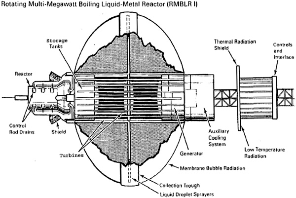


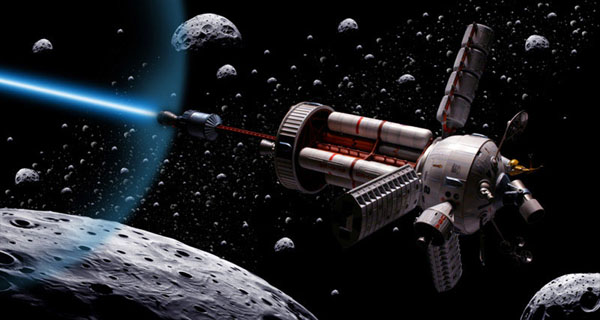


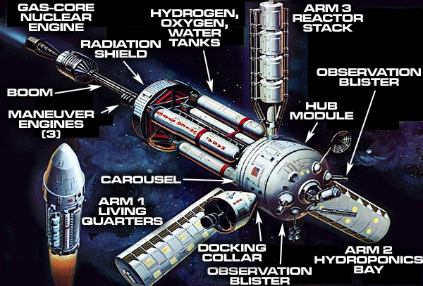


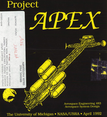


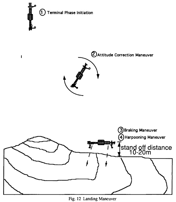


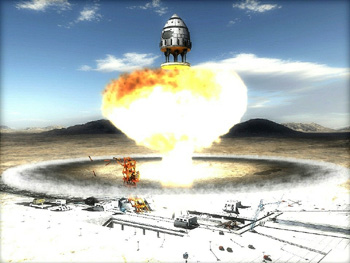


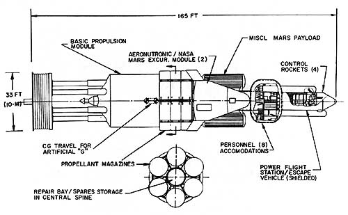


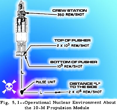
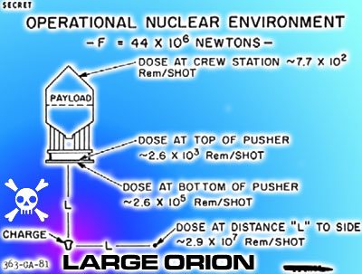
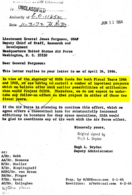


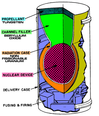


 Note pusher oil spray coating bottom of pusher plate with ablative silicone oil


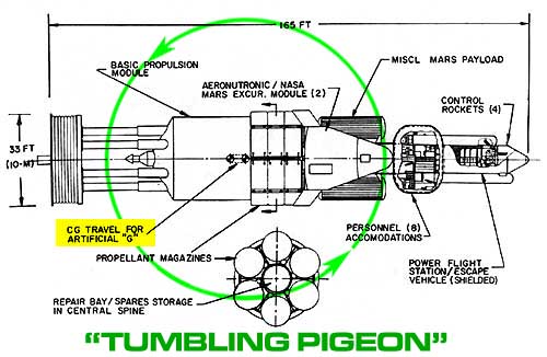


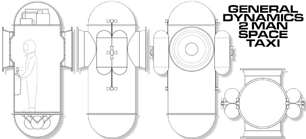
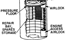
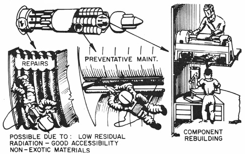


 Planet: Destination planetclick for larger image