The RS 10 from Star Born by Andre Norton, 1957. Artwork by Dean Ellis. Judging from the size of the people, the ship is approximately 128 meters high (420 feet). Ain't that a beauty?
Beamed Power
Laser Thermal
Laser Thermal
Exhaust Velocity
40,000 m/s
Specific Impulse
4,077 s
Thrust
13,000 N
Thrust Power
0.3 GW
Mass Flow
0.33 kg/s
Total Engine Mass
20,000 kg
T/W
0.07
Thermal eff.
30%
Total eff.
30%
Fuel
External Laser
Reactor
Collector Mirror
Remass
Seeded Hydrogen
Remass Accel
Thermal Accel: Collector Mirror
Thrust Director
Nozzle
Specific Power
77 kg/MW
Similar to Solar Moth, but uses a stationary ground or space-station based laser instead of the sun. Basically the propulsion system leaves the power plant at home and relies upon a laser beam instead of an incredibly long extension cord.
As a general rule, the collector mirror of a laser thermal rocket can be much smaller than a comparable solar moth, since the laser beam probably has a higher energy density than natural sunlight.
With the mass of the power plant not actually on the spacecraft, more mass is available for payload. Or the reduced mass makes for a higher mass ratio to increase the spacecraft's delta V. The reduced mass also increases the acceleration. In some science fiction novels, combat "motherships" will have batteries of lasers, used to power hordes of ultra-high acceleration missiles and/or fighter spacecraft.
The drawback include the fact that there is a maximum effective range you can send a worthwhile laser beam from station to spacecraft, and the fact that the spacecraft is at the mercy of whoever is controlling the laser station.
Propellant is hydrogen seeded with alkali metal. As always the reason for seeding is that hydrogen is more or less transparent so the laser beam will mostly pass right through without heating the hydrogen. The seeding make the hydrogen more opaque so the blasted stuff will heat up. Having said that, the Mirror Steamer has an alternate solution.
The equations for delta V and mass ratio are slightly different for a Solar Moth or Laser Thermal rocket engine:
Δv = sqrt((2 * Bp * Bε) / mDot) * ln[R]
R = e(Δv/sqrt((2 * Bp * Bε) / mDot)
where
Δv = ship's total deltaV capability (m/s)
R = ship's mass ratio
Bp = Beam power (watts) of either laser beam or solar energy collected
Bε = efficiency with which engine converts beam power into exhaust kinetic energy (0.0 to 1.0, currently about 0.3)
ln[x] = natural logarithm of x, the "ln" key on your calculator
ex = antilog base e or inverse of natural logarithm of x, the "ex" key on your calculator
Mirror Steamer Robonaut patent card from the game High Frontier.
BEAMED POWER PROPULSION
So, an extended BFR spacecraft that consists of a 150 tonne payload and 170 tonne structure (twice the 85 tonne structure weight of a standard BFR starship) which includes a hydrogen tank that carries 500 tonnes of liquid hydrogen in a long duration zero boil off tank, as well as 600 tonnes of LOX, along with large inflatable concentrators.
A laser beam is focused on the ship and the receiver optics focus the laser beam into the engine where it heats liquid hydrogen to 40 km/sec (exhaust velocity of 40,000 m/s, specific impulse of 4,000 sec). The other 700 tonnes of propellant is used in a hydrogen/oxygen rocket through the same nozzle which has a 4.5 km/sec exhaust speed (Isp of 450 sec). This permits the ship to carry out maneuvers without being illuminated by the laser beam. This also is used as an energy storage medium to take water carried aboard ship, along with water ice found in situ — and produce hydrogen and oxygen with it using laser energy received from Earth.
This makes use of a solar pumped laser power satellite that is developed to be deployed by the BFR system — and operate to generate energy for use on Earth and other inhabited worlds.
In this case the 9 GW solar pumped laser is used with a large projector system launched by a second BFR to beam energy from Earth orbit to the vicinity of Jupiter. This laser beam is used to heat hydrogen in a laser theraml rocket described above. It may also be used to use high temperature electrolysis to break down water into hydrogen and oxygen. In this way the ship is capable of extended duration missions and refueling using water ices found in the outer solar system.
Now during launch the ‘Jupiter Stage’ is equipped with 600 tonnes of LOX and 100 tonnes of LH2. It masses 170 tonnes empty and can carry 46 tonnes during launch burning through the 700 tonnes of propellant.
After in orbit, another 104 tonnes of equipment is added with a ferry flight, along with another 1,100 tonnes of propellant. 600 tonnes of LOX, 500 tonnes of LH2. This requires another 8 flights of specially constructed tanker and ferry stage.
The 400 tonnes of LOX combined with 50 tonnes of LH2 produce 450,000 liters of water along with 6.005 trillion joules. A lot of energy. It could supply 1 MW for nearly 10 weeks nonstop.
Used as propellant the 700 tonnes of LOX/LH2 can impart 3.05 km/sec to the ship carrying its payload and 400 tonnes of LH2. Without is LH2 tank (and associated engine and optics) it can impart 6.21 km/sec to the ship — used as a separate landing craft.
The 400 tonnes of LH2 when energised by the 9 GW laser imparts another 13.23 km/sec to the system.
LOX/LH2 — 4.5 km/sec — 3.05 km/sec delta v
100 tonnes — LH2 — 0.083 t/m3 — 1204.82 m3
600 tonnes — LOX — 1.14 t/m3 — 536.32 m3
Laser/LH2 — 40.0 km/sec — 13.23 km/sec delta v.
400 tonnes — LH2 — 0.083 t/m3 — 4,819.28 m3
Total (without refueling) — 16.28 km/sec delta v.
At peak velocity the 9 GW laser can energise 11.25 kg/sec of liquid hydrogen. This produces 450 kN thrust (101,160 lbf). This produces 0.3169 m/s2 or 1/5th the acceleration on the surface of the Moon.
A 12 meter diameter spherical tank stores the required LOX.
The smaller LH2 tank has an 10.7 meter long cylinder attached to the sphere with a 12 meter wide and 6 meter tall hemispherical end cap.
The larger LH2 tank has a 42.6 meter long cylinder attached to the other side of the LOX sphere with a 12 meter wide and 6 meter tall hemispherical end cap — which is detachable from the LOX tank along their common bulkhead.
Around the common bulkhead is a ring of LOX/LH2 engines and separate landing gear.
Around the end of the large LH2 tank is the laser receiver optics and the laser engine.
Assembled the tank system is 12 meters in diameter and 65.3 meters long including the hemispherical end caps. With 22.3 meters nose section atop the short liquid hydrogen tank the entire upper stage is 55 m long without the larger LH2 tank. And is 87.6 meters long with the larger liquid hydrogen tank.
So, the upper stage would look like the BFR at launch with a half height Heavy Booster attached on Orbit.
The inflatable solar collector that powers the laser is 3.6 km in diameter. A similar sized inflatable projector beams the 1000 nm wavelength light (longest wavelength) up to 6.203 AU from the Earth. This creates a receiver size 315 meters in diameter. At 4.203 AU and 850 nm wavelength 185 meters is sufficient.
The larger reflector masses 2.15 metric tons!
To boost to Jupiter requires a hyperbolic excess velocity of 12.34 km/sec which requires 9.00 km/sec delta v from LEO. It takes 7 hours 54 minutes to boost to this speed using the laser rocket.
It then takes 2.731 years to get to Jupiter.
At Jupiter the ship is moving 7.418 km/sec. Jupiter is moving at 13.064 km/sec a difference of 5.646 km/sec.
Jupiter has an escape velocity of 60.2 km/sec. So, aerobraking at the surface of Jupiter to slow into orbit around the planet, the ship arrives with this hyperbolic excess, so arrives at Jupiter’s cloud tops at 60.465 km/sec and must be slowed by 17.710 km/sec to enter low orbit. Less if the ship is to enter an elliptical orbit taking it to one of the Moons.
Ganymede is an interesting moon to visit — and base exploration from.
So, going from one Jovian radius to 15.311 Jovian radii away — means that we must go from
sqrt(2/1–1/8.1555) = 1.37018 times Jupiter orbital velocity.
60.2 km/sec — Jupiter escape velocity
So, 58.616 km/sec is the speed that gets you to Ganymede from Jupiter’s cloud tops to you subtract off only 1.849 km/sec as you Swing by Jupiter.
If you wanted to avoid the deep dive into Jupiter’s cloud tops, you could drop into Ganymede directly and fire your rockets to enter orbit. There is sufficient delta v to do that. As well as sufficient delta v to get back from Ganymede orbit.
Average orbital speed is 10.88 km/sec for Ganymede. Escape velocity from that radius (1.07 million km) is 15.39 km/sec.
So arriving at Ganymede with a perijovian distnace of 1.07 million km it will have an excess speed of 16.406 km/sec. A delta v of 5.526 km/sec to come to a dead top relative to Ganymede.
Of course Ganymede has an escape velocity of its own. 2.741 km/sec. So, an object would hit Ganymede with a speed of 6.169 km/sec — and to come to rest on Ganymede requires that much speed be cancelled. Of course if you enter orbit around Ganymede you need only cancel 4.231 km/sec.
Which lets you arrive empty hydrogen tank at the Moon.
1.938 km/sec lands you from Ganymede orbit to Ganymede surface — this uses your LOX/LH2 rockets. You land with your laser receiver and empty hydrogen tank — and begin using laser energy to process water ice into propellant. You also use unusued LOX/LH2 to power fuel cells aboard the ship for times when the ship is not in direct line of sight of Earth’s laser.
Of course you modulate the laser, and use a counter propagating beam to steer your laser and provide two way broadband.
Every 1.092 years the Earth is in a position to fly from Jupiter to Earth along a minimum energy trajctory. The first return window is 200 days after arrival, and then every 400 days.
Now 500 tonnes of LH2 requires the decomopsition of 4500 tonnes of water ice on Ganymede. A ball of water 20.48 meters in diameter (67.2 ft) Not particularly large.
At 9 GW it takes only 2 hours 11 minutes 19 seconds to process this much water at 100% efficiency. With 70 days of illumination by laser over the 200 days on the surface only 18 MW of laser energy is required with a 65% efficient electrolysis unit.
LOX/LH2 is used as propellant to power Flyboards used by the explorers to travel and visit all parts of the moon. A small satellite array is released upon descent, to form a GPS/StarLink/Mapping network to guide the explorers and help them move around the surface.
If there is an okay to stay another Synodic period, another moon can be explored after refuelling on Ganymede. In this way the major satellites may be visited.
Dr. Mark Roth says that suspended animation is within our grasp. This is something to consider for the Jupiter expedtion. Putting robots and AI in charge of the ship for over two years and putting humans in suspended animation during long transit saves resources improves safety increases crew size and flexibility, and eases psychological burdens of long duration flight whilst proving systems that will be used in longer duration insterstellar voyages.
The entire trip takes 7 years to complete 2.75 years outbound, 1.50 years in the Jovian system, and 2.75 years inbound.
A rocket can be driven by high-energy, short-duration
(<10-10 sec) laser pulses, focused on a solid propellant.
A double-pulse system
is used: the first pulse ablates material and the second further heats the ablated
gas. A low Z propellant, such as graphite, obtains the best specific impulse
(4 ksec). Unfortunately, ice is not a suitable medium due to melting and “dribbling”
losses.
Primary and secondary mirrors focus the pulses at irradiances of 3 × 10¹³
W/cm2. The mass-removal rate is 3 μg per laser pulse. Powered with a 60 MW
beam, an ablative laser thruster has a thrust of 2.4 kN and, with a fuel tuned to the
firing sequences and an efficient double-pulsed shape, the overall efficiency is 80%.
“Specific impulse and other characteristics of elementary propellants for ablative laser propulsion”, Dr. Andrew V. Pakhomov,
Associate Professor at the Department of Physics, UAH, 2002.
As an important point, the practical minimum acceleration for a spacecraft is about 5 milligees. Otherwise it will take years to change orbits. Photon sails can only do up to 3 milligees, but a laser sail can do 5 milligees easily.
Solar Moth
Solar Moth
Exhaust Velocity
9,000 m/s
Specific Impulse
917 s
Thrust
4,000 N
Thrust Power
18.0 MW
Mass Flow
0.44 kg/s
Total Engine Mass
100 kg
T/W
4
Thermal eff.
65%
Total eff. (Bε)
65%
Fuel
Solar Photons
Reactor
Collector Mirror
Remass
Liquid Hydrogen
Remass Accel
Thermal Accel: Collector Mirror
Thrust Director
Nozzle
Specific Power
6 kg/MW
Solar thermal rocket. 175 meter diameter aluminum coated reflector concentrates solar radiation onto a window chamber hoop boiler, heating and expanding the propellant through a regeneratively-cooled hoop nozzle. The concentrating mirror is one half of a giant inflatable balloon, the other half is transparent (so it has an attractive low mass).
The advantage is that you have power as long as the sun shines and your power plant has zero mass (as far as the spacecraft mass is concerned). The disadvantage is it doesn't work well past the orbit of Mars. The figures in the table are for Earth orbit.
The solar moth might be carried on a spacecraft as an emergency propulsion system, since the engine mass is so miniscule.
The equations for delta V and mass ratio are slightly different for a Solar Moth or Laser Thermal rocket engine:
Δv = sqrt((2 * Bp * Bε) / mDot) * ln[R]
R = e(Δv/sqrt((2 * Bp * Bε) / mDot)
where
Δv = ship's total deltaV capability (m/s)
R = ship's mass ratio
Bp = Beam power (watts) of either laser beam or solar energy collected
Bε = efficiency with which engine converts beam power into exhaust kinetic energy (0.0 to 1.0)
ln[x] = natural logarithm of x, the "ln" key on your calculator
ex = antilog base e or inverse of natural logarithm of x, the "ex" key on your calculator
For the Solar Moth in the data block Bε = 0.65, for the Mirror Steamer Bε = 0.87
Bp = Marea * (☉constant * (1 / (☉dist2)))
where
Bp = Beam power (watts) of solar energy collected
Marea = total area of collecting mirrors (m2)
☉dist = distance between Sun and spacecraft (Astronomical Units, Earth = 1.0)
☉constant = Solar Constant = varies from 1,361 w/m2 at solar minimum and 1,362 w/m2 at solar maximum (w/m2)
1.0 astronomical units is defined as 149,597,870,700 meters.
1 / (☉dist2) is the sunlight energy density. In Earth's orbit, the density is 1.0, at Mars orbit it is 0.44 (44%), at Jupiter orbit it is 0.037, at Neptune orbit it is 0.001, at Mercury orbit it is 6.68.
Mirror Steamer Robonaut
Mirror Steamer Robonaut patent card from the game High Frontier.
Mirror Steamer
Exhaust Velocity
9,810 m/s
Specific Impulse
1,000 s
Thrust
2,600 N
Thrust Power
12.8 MW
Mass Flow
0.27 kg/s
Total Engine Mass
20,977 kg
T/W
0.01
Frozen Flow Efficency
97%
Thermal Efficency
90%
Total Efficency (Bε)
87%
Fuel
Solar Photons
Reactor
Collector Mirror
Remass
Liquid Hydrogen
Remass Acceleration
Thermal Acceleration: Collector Mirror
Thrust Director
Nozzle
Specific Power
1,645 kg/MW
Water is an attractive volumetric absorber for infrared laser propulsion. Diatomic species formed from the disassociation of water such as OH are present at temperatures as high as 5000 K, and can be rotationally excited by a free electron laser operating in the far infrared. The OH molecules then transfer their energy to a stream of hydrogen propellant in a thermodynamic rocket nozzle by relaxation collisions.
Beamed heat can also be added by a blackbody cavity absorber. This heat exchanger is a series of concentric cylinders, made of hafnium carbide (HfC). Focused sunlight or lasers passes through the outermost porous disk, and is absorbed in the cavity. Heat is transferred to the propellant by the hot HfC without the need for propellant seeding. The specific impulse is materials-limited to 1 ks.
“Solar Rocket System Concept Analysis”, F.G. Etheridge, Rockwell Space Systems Group. (I resized the Rockwell “Solar Moth” design for 3 kN thrust).
It would consist of a huge bubble of transparent
polyester plastic. The
bubble could be some 300 feet (90 m) in diameter
with a skin only a thousandth of an inch (0.0254 mm)
thick. It would be slightly ressurized to give it a spherical shape. Half
the inside surface would he silvered to
create a hemispherical mirror that would
concentrate the sun's rays on a heating
element. In this element the hydrogen
would be vaporized.
Piped to directable nozzles, one at each
side of the sphere, the gas would provide
thrust for acceleration, braking and maneuvering. The crew's gondola and associated equipment including solar battery for
auxiliary power would he supported by a
framework in the center of the big sphere.
It should he remembered that a space
ship uses power only during its initial acceleration. The vehicle coasts the rest of
the trip. Nevertheless it should carry large
reserves of propellant.
Here the solar drive has real advantage.
Its heat-collecting device, the hemispherical mirror, weighs possibly 1000 pounds (450 kg) as
compared to a much greater weight of oxidizer that would need to be carried in a
comparable chemical rocket. This saving in
weight permits additional hydrogen to be
carried.
Solar drive provides low thrust as compared to the very high thrust of a chemical
rocket. This is a good thing, for the fragile
plastic bubble will tolerate only low accelerations. It will be necessary to remain
under power for hours to achieve the acceleration obtained in minutes by a chemical power plant.
click for larger image
click for larger image (image quality is very poor)
click for larger image (image quality is very poor)
From POPULAR MECHANICS March 1957
Sunlight bounces from primary reflector to secondary reflector. Then it travels to the "transfer optics", a diagonal mirror that bounces the sunlight into the thermal collector on the rocket engine.
From Solar Rocket System Concept Analysis (1979)
Off-axis parabolic inflatable mirror concentrates sunlight on the cavity aperture of the rocket engine.
From Solar Rocket System Concept Analysis (1979)
Interior mirrored surface prevents misfocused sunlight from frying the spacecraft like an ant under a magnifying glass on a sunny day. From Solar Rocket System Concept Analysis (1979)
Rocketdyne heat exchanger thruster. Hydrogen propellant. Temperature 2,700 K. Thrust 3.7 newtons. Exhaust velocity 7,800 m/sec. From NASA SP-509
Robot Asteroid Prospector (RAP)
Solar thermal propulsion (the two mirrored dishes, solar moth with water propellant) also supplies process heat for mining and refining, and one megawatt of electricity from a Stirling cycle engine.
From Asteroid Mining AIAA-2013-5304
Noted space artist Nick Stevens has been working on visualizing a Solar Moth.
“A sun-powered space ship of tomorrow – the crew rides in the gondola with radar antennas. Designed by Krafft A. Ehricke of [the] Convair division of General Dynamics Corp.”
Mike Acs: Two engines facing away from the viewer, fed by two fuel lines, coming from the large spherical solar collector/concentrator, and partially girdling the central sphere — appear to be firing. Beautiful work by Convair's prolific and talented artist/illustrator — John Sentovic.
Painting by Professor Sol Dember
Chemical
A barely contained chemical explosive. Noted for very high thrust and very low exhaust velocity. One of the few propulsion systems where the fuel and the propellant are the same thing. There is a list of chemical propellants here
Storeable vs Cryogenic
in chemical rocket in general and NASA proposed Mars missions in particular, they talk a lot about storeable fuel as opposed to cryogenic fuel. Let me explain.
The main problem is that you want the fuel to be both:
have the highest possible exhaust velocity/specific impulse
be liquid
A high exhaust velocity means the fuel has the most "bounce for the ounce", which is important since the performance of even the best chemical fuels is pretty much at the bottom of the list of propulsion systems.
Having the fuel be liquid is vital, since if the fuel is gaseous the tank will have to be so huge that the empty tank mass will brutally cut into the spacecraft's payload mass.
Cryogenic Fuels
The problem is that NASA designs want to have the tank at "normal" temperatures, meaning temperatures you'd expect around the orbits of Terra or Mars.
The highest (non-outrageously dangerous) exhaust velocity fuel is Hydrogen-Oxygen. Trouble is that at normal temperatures, both of those are gas, not liquid.
Fuel tanks full of gaseous hydrogen and gaseous oxygen will be a non-starter. The tanks would be bigger than Godzilla's testicles because of the incredibly low density. This means the tank skin mass would be prohibitive because even walls as thin as foil take up lots of mass when enclosing such a huge volume.
So you have turn the gases into liquids with a reasonable density by cooling them down. Oxygen liquefies into LOX (liquid oxygen ) below −182 °C at standard pressure. You have to cool of hydrogen to below −252 °C before the blasted stuff liquefies. Such ultra-cooled liquids are called cryogenic, and the fuels are called cryogenic fuels.
Now the trouble is keeping them that cold. Sunlight will rapidly heat the tank up, and even in the tank is shaded it has to be connected to the rocket engine. The liquid oxygen and liquid hydrogen will start vaporizing into gas (called "boiling") as the temperature rises above the boiling point. Since the vapor phase takes up far more space than the liquid phase, the pressure in the tank rises. The tank has to be flimsy since every gram counts. Eventually the freaking tank explodes. All die. O the embarrassment.
As a safety measure, such tanks are routinely equipped with pressure relief valves. When the pressure approaches the exploding point, the valve pops open to let some gas escape. The good part is this prevents the tank from blowing up. The bad part is that this lets vital fuel escape into space and eventually the entire tank boils dry. The technical term is "boil-off loss",
We don't want the tanks exploding, but we don't want all the fuel escaping either. There are some NASA designs that deal with this by frantically burning all the cryogenic fuel for the Trans-Mars Injection Burn; then using some other propulsion system for the Mars Orbit Insertion burn, the Trans-Earth Injection burn, and the Earth Orbit Insertion burn. Which is a kludge.
The other solution is to remove the heat that is invading the fuel tanks, that is, to refrigerate them. This keeps the fuel tanks from exploding and the fuel from boiling away. The cost is that the refrigeration equipment cuts into the payload mass, and the equipment requires electrical power. NASA Mars mission ships often have extra solar panels to feed the refrigerator, also cutting into the payload mass.
Storeable Fuels
All of this complication can be avoided if the engines can use chemical fuels which are liquid at normal temperatures. These are called storeable fuels. Even better, the fuel can be hypergolic, meaning the stuff explodes on contact instead of needing a pilot light or other ignition system as do other chemical fuels. Being hypergolic also prevents large amounts of fuel and oxidizer accumulating in the nozzle before ignition, which can cause a "hard start" (like a car backfiring) or "engine catastrophic failure" (exploding like a bomb).
However, NASA doesn't like using storeable fuels because their exhaust velocities sucks rocks through a garden hose. LOX-LH2 exhaust velocity is barely adequate, storeable fall below the "unacceptable" level. I remember reading a report about a NASA Mars mission where the upper stages were all storeable, but you could tell their heart wasn't really in it. The mission payload was pathetic.
Nuclear thermal rockets have to use cryogenic tanks because they must use liquid hydrogen. They don't work very well with hypergolic fuels.
About the only place NASA uses storeable are with reaction control systems. In that application the exhaust velocity is not as critical, but storeability and hypergolic ignition paramount.
Methane and oxygen ("methalox" or CH4/O2) are burned resulting in an unremarkable specific impulse of about 377 seconds. However, this is the highest performance of any chemical rocket using fuels that can be stored indefinitely in space. Chemical rockets with superior specific impulse generally use liquid hydrogen, which will eventually leak away by escaping between the the molecules composing your fuel tanks. Liquid methane and liquid oxygen will stay put. Methane is also easier to produce by in-situ resource utilization.
The Sabatier reactor uses In-Situ
Resource Utilization (ISRU) to create a closed hydrogen and
oxygen cycle for life support on planets with CO2 atmospheres
such as Mars or Venus.
It contains two chambers, one for
mixing and the other for storing a nickel catalyst. When charged
with hydrogen and atmospheric carbon dioxide, it produces
water and methane. (The similar Bosch reactor uses an iron
catalyst to produce elemental carbon and water.)
A condenser
separates the water vapor from the reaction products. This
condenser is a simple pipe with outlets on the bottom to collect
water; natural convection on the surface of the pipe is enough
to carry out the necessary heat exchange.
Electrolysis of the
water recovers the hydrogen for reuse.
Hydrogen and oxygen are burned resulting in close to the theoretical maximum specific impulse of about 450 seconds. However, liquid hydrogen cannot be stored permanently in any tank composed of matter. The blasted stuff will escape atom by atom between the molecules composing the fuel tanks.
The combustion of the cryogenic fuels
hydrogen and oxygen produces an ideal specific impulse of 528
seconds. The product is water, which is exhausted through a
converging-diverging tube called a De Laval nozzle.
The engine
illustrated is similar to the Space Shuttle main engine, with a
specific impulse of 460 seconds. The De Laval nozzle has a 180:1 area ratio, and is
regeneratively-cooled with liquid hydrogen. The chamber
temperature is 3500K, and the chamber pressure is 2.8 MPa. The
engine has a thermal efficiency of 98%, a mixture ratio of 5.4, and a
frozen-flow efficiency of 55%. A 2000 MWth chamber generates
440 kN of thrust and a thrust to weight ratio of one gravity.
Space
Transportation Systems, American Institute of Aeronautics and Astronautics, 1978.
RP-1 is Rocket Propellant-1 or Refined Petroleum-1) is a highly refined form of kerosene outwardly similar to jet fuel, used as rocket fuel. It is not as powerful as liquid hydrogen but it is a whole lot less trouble. Compared to LH2 it is cheaper, stabler at room temperature, non-cryogenic less of an explosive hazard, and denser.
Both are hypergolic, meaning the stuff explodes on contact with each other instead of needing a pilot light or other ignition system as do other chemical fuels. This means one less point of failure and one less maintenance nightmare on your spacecraft. Being hypergolic also prevents large amounts of fuel and oxidizer accumulating in the nozzle, which can cause a hard start or engine catastrophic failure (fancy term for "engine goes ka-blam!"). It is also non-cryogenic, liquid at room temperature and pressure. This means it is a storable liquid propellant, suitable for space missions that last years.
"Ah, what's the catch?" you ask.
The catch is that the mix is hideously corrosive, toxic, and carcinogenic. It is also easily absorbed through the skin. If UDMH escapes into the air it reacts to form dimethylnitrosamine, which is a persistent carcinogen and groundwater pollutant. MMH is only fractionally less bad.
This is the reason for all those technicians wearing hazmat suits at Space Shuttle landings. The Shuttle used MMH/NTO in its reaction control thrusters. Upon landing the techs had to drain the hellish stuff before it leaked and dissoved some innocent bystander.
In the words of Troy Campbell, hypergolic fuels are tanks full of explosive cancer.
Back in the old days (pre-1950s) things were even more dangerous. Instead of nitrogen tetroxide for oxidizer, they used red fuming nitric acid (RFNA). While NTO can cause skin burns and is lethal to inhale, fuming nitric acid will actually dissolve human flesh. The only reason anybody used the deadly stuff for rocket oxidizer is because it was commonly used in German WWII rockets (in S-Stoff and SV-Stoff). By the late 1950s RFNA had been replaced by NTO
Aluminum and oxygen are burned resulting in an unremarkable specific impulse of
about 285 seconds. However, this is of great interest to any future lunar colonies. Both aluminum and oxygen are readily available in the lunar regolith, and such a rocket could easily perform lunar liftoff, lunar landing, or departure from a hypothetical L5 colony for Terra (using a lunar swingby trajectory). The low specific impulse is more than made up for by the fact that the fuel does not have to be imported from Terra. It can be used in a hybrid rocket (with solid aluminum burning in liquid oxygen), or using ALICE (which is a slurry of nanoaluminium powder mixed in water then frozen).
Of course the aluminum oxide in lunar regolith has to be split into aluminum and oxygen before you can use it as fuel. But Luna has plenty of solar power. As a general rule, in space, energy is cheap but matter is expensive.
Although aluminum is
common in space, it stubbornly resists refining from its oxide
Al3O2. It can be reduced by a solar carbothermal process,
using carbon as the reducing agent and solar energy.
Compared to carbo-chlorination, this process needs no
chlorine, which is hard to obtain in space. Furthermore, the
use of solar heat instead of electrolysis allows higher
efficiency and less power conditioning. The solar energy
required is 0.121 GJ/kg Al.
The aluminum and oxygen produced can be used to fuel Al-O2 chemical
boosters, which burn fine sintered aluminum dust in the presence of liquid
oxygen (LO2). Unlike pure solid rockets, hybrid rockets (using a solid fuel
and liquid oxidizer) can be throttled and restarted. The combustion of
aluminum obtains 3.6 million joules per kilogram. At 77% propulsion
efficiency, the thrust is 290 kN with a specific impulse of 285 seconds.
The mass ratio for boosting off or onto Luna using an Al-O2 rocket is 2.3.
In other words, over twice as much as much fuel as payload is needed.
Gustafson, White, and Fidler of ORBITECTM, 2010.
Carbochlorination Refinery
Metal sulfates may be refined by exposing
a mixture of the crushed ore and carbon dust to streams of chlorine
gas. Under moderate resistojet heating (1123 K) in titanium chambers
(Ti resists attack by Cl), the material is converted to chloride salts such
as found in seawater, which can be extracted by electrolysis.
The
example shown is the carbochlorination of Al2Cl3 to form aluminum.
Al is valuable in space for making wires and cables (copper is rare in
space). The electrolysis of Al2Cl3 does not consume the electrodes
nor does it require cryolite. However, due to the low boiling point of
Al2Cl3, the reaction must proceed under pressure and low temperatures.
Other elements produced by carbochlorination include titanium,
potassium, manganese, chromium, sodium, magnesium, silicon and
also (with the use of plastic filters) the nuclear fuels 235U and 232Th.
Both C and Cl2 must be carefully recycled (the recycling equipment
dominates the system mass) and replenished by regolith scavenging.
Propulsion Fuels From Indigenous Lunar And Asteroidal Metals
Table 1: Metal/Oxygen Combustion Properties
Metal
Specific Enthalpy (joules/kg)
Isp (seconds)
hydrogen
1.39×10⁷
457
aluminum
1.63×10⁷
270
calcium
1.41×10⁷
213
iron
4.7×10⁶
184
magnesium
1.83×10⁷
260
silicon
1.58×10⁷
272
titanium
1.17×10⁷
255
Lunar and asteroidal surface materials are ubiquitous and abundant
sources of metals like silicon, aluminum, magnesium, iron, calcium, and
titanium. Many schemes have been proposed for extracting these metals
and oxygen for structural, electrical, and materials processing space
operations.
However, all the metals burn energetically in oxygen and could
serve as in-situ rocket fuels for space transportation applications.
Table 1 lists the specific heats of combustion (enthalpy) at 1800 K and
corresponding specific impluses at selected mixture ratios with oxygen of the
above pure metals assuming rocket combustion at 1000 psia and an expansion
ratio of 50. Hydrogen is included for comparison.
All the metals appear to offer adequate propulsion performance from low
or moderate gravity bodies and are far more abundant than hydrogen on many
terrestrial planets and asteroids.
It is noteworthy that silicon, the most
abundant nonterrestrial metal, is potentially one of the best performers. In
addition, iron with the lowest specific impulse is sufficiently energetic for
cislunar and asteroidal transportation. Further, silicon and iron are the most
readily obtained nonterrestrial metals. They can be separated by distillation
of basalts and other nonterrestrial silicates in vacuum solar furnaces.
Efficient rocket combustion of metal fuels could be realized by
injecting them as a fine powder into the combustion chamber. This could be
done by mixing the fuel with an inert carrier gas or in liquid oxygen (LOX) to
form a slurry. Preliminary studies indicate that a mixture of metal/LOX can be
stored and handled safely without danger of autoignition. Lean fuel mixtures
would be used to achieve the maximum specific impluse by reducing the exhaust
molecular weight without excessivly lowering the combustion temperature. Two
phase flow losses are estimated to be acceptable for anticipated throat sizes
based on measured thrust loss data from solid rocket motors ustng aluminized
propellants.
The metals could be atomized by condensing droplets in vacuum from a
liquid metal stream forced through a fine ceramic nozzle. Brittle metals like
silicon and calcium might be pulverized to sub 20 micrometer size in vacuum in
autogenous grinders that operate by centrifugal impact and are independent of
the gravity level.
From Propulsion Fuels From Indigenous Lunar And Asteroidal Metals by William N. Agosto and John H. Wickman
Metastable
Atomic Hydrogen
100% Atomic Hydrogen
Exhaust velocity
20,600 m/s
15% Atomic Hydrogen in solid H2
Exhaust velocity
7,300 m/s
Single-H/LOX
Exhaust Velocity
4,600 m/s
Specific Impulse
469 s
Ordinary hydrogen is a molecule composed of two atoms of hydrogen bonded together. This is called molecular hydrogen and is quite stable.
If the gas was composed not of molecules but instead of atoms of hydrogen, you would of course have atomic hydrogen. This is also called free-radical hydrogen. Robert Heinlein calls it "single-H".
The great thing about single-H is that in a solid-core nuclear thermal rocket it has double the exhaust velocity and specific impulse of ordinary H2 molecular hydrogen. A whopping 16,000 m/s exhaust velocity, compared to only 8,000 m/s or so from H2. This is because the exhaust velocity increases as the mass of the propellant particle decreases. Obviously an H1 atom has half the mass of an H2 molecule.
What's the catch? The problem is that it desperately wants to recombine into H2. In other words the blasted stuff explodes like a bomb at the clank of a falling dust speck. It explodes with a force about fifty times more powerful than the same mass of TNT.
In Heinlein's science fiction, he just waves his hands, says the stuff is quote "stabilized" unquote, and left the details of stabilization as an exercise for the reader.
In the real world, the least unreasonable way of preventing recombination is to make a solid mass of frozen hydrogen (H2) at liquid helium temperatures which contains no more than 15% single-H by weight. You don't get as much of an increase in exhaust velocity, but at least your spacecraft doesn't blow up.
The next-less unreasonable way of preventing this is to have the engine heat the propellant above 5,000K. This is hot enough to split safe molecular hydrogen from the propellant tank into atomic hydrogen. You'll need a real hot engine though. Solid-core nuclear thermal rockets are only good up to about 3,000K before the reactor melts.
SINGLE-H, WHOSE BRIGHT IDEA WAS THIS?
Bill Higgins-- Beam Jockey: Changing the subject somewhat--because you seem like a good group of people to ask--what's the story with monatomic hydrogen? Why did anybody think it could be made and stored in rocketry quantities?
Robotbeat: I think people have considered it. On an extremely theoretical basis. And it has wormed its way into scifi because of it. This is really a question for Winchell Chung
John Woodford: Yes, it shows up in Heinlein's Space Cadet (1948) as the propellant of choice for modern rockets. He probably used it elsewhere, but I can't recall any examples.
Fritz Zwicky pioneered “general morphological analysis” in examining types of rocket engines and a range of propellants. Beginning in 1943, proposals for what Zwicky termed “meta-chemistry” circulated within Aerojet Engineering Corporation. Zwicky described meta-chemistry as dealing “with the study, production and the use of quantum mechanically metastable particles, molecules or states of matter in general” More recently, such propellants have been referred to as “HEDM”, high-energy density materials.
Zwicky investigated metachemistry propellants in an effort to avoid what he termed the “carbon dilemma” of hydrocarbon fuels, i.e., fuels that included carbon in the chemistry were therefore subject to lower specific impulses because carbon atoms are heavier than hydrogen atoms and the carbon might not completely combust producing CO instead of CO2. As an example of what could be achieved with metachemistry, Zwicky noted that the reaction of monatomic hydrogen with monatomic hydrogen (H + H = H2) liberated 51.9 kcal/g as compared with 0.63 and 1.51 kcal/g for TNT and nitroglycerine respectively. Zwicky said that the reaction H + H = H2 gave a limiting specific impulse of 21 km/s.
1957: Zwicky’s Monatomic Hydrogen Single-H fever dream continued in “Propellants for Tomorrow’s Rockets”, collected in PROPULSION TECHNIQUES: ACTION & REACTION, ed by Peter J Turchi. Google Books reveals part of this chapter. Original appearance of "Propellants for Tomorrow's Rockets:" F. Zwicky. ASTRONAUTICS, Vol 2, Aug 1957, pp 45-49, 95-97.
I knew of Monatomic Hydrogen from a Heinlein story; Palaszewski & Bennett mention 1950 film ROCKETSHIP X-M, in which propellants are "atomic hydrogen and ozone." Everyone in Hollywood was reading Zwicky back then, I guess. I might have known this, had I ever gotten around to watching ROCKETSHIP X-M. (A movie famous for having been made more quickly & cheaply than Heinlein's own DESTINATION MOON, but released earlier to pilfer DM's publicity.)
Oh, if you DO have access to CHEMICAL & ENGINEERING NEWS, here's a link to Zwicky's 1950 paper "Chemical Kinetics & Jet Propulsion." Monatomic Hydrogen isn't the only goofy idea in there. I now believe that Monatomic Hydrogen was a speculative conjecture only on paper, not lab work, let alone any design of pumps or tanks, etc. Every decade, one or two daydreamers mention Zwicky's Single H stuff in the literature again.
Free radicals are single atoms of
elements that normally form molecules. Free radical hydrogen (H)
has half the molecular weight of H2.
If used as propellant, it doubles
the specific impulse of thermodynamic rockets.
If used as fuel, its
specific energy (218 MJ/kg) produces a theoretical specific impulse
of 2.13 ksec.
Free radicals extracted by particle bombardment are
cooled by VUV laser chirping, and trapped in a hybrid laser-magnet
as a Bose-Einstein gas at ultracold temperatures. A Pritchard-Ioffe
trap keeps their mobile spins aligned, using the interaction of the
atomic magnetic moment with the inhomogeous magnetic field. The
trapping density of >1014 atoms/cc is much higher than in Penning
traps.
Free radical deuterium that has been spin-vector polarized is
stable against ionization and atomic collisions. Because of its large
fusion reactivity cross-sectional area, it makes a useful fusion fuel.
Hydrogen (H2) subjected to enough pressure to turn it into metal (mH), then contained under such pressure. Release the pressure and out comes all the stored energy that was required to compress it in the first place.
It will require storage that can handle millions of atmospheres worth of pressure. The mass of the storage unit might be enough to negate the advantage of the high exhaust velocity.
Or maybe not. The hope is that somebody might figure out how to compress the stuff into metal, then somehow release the pressure and have it stay metallic. In Properties of Metallic Hydrogen under Pressure the researchers showed that hydrogen would be a metastable metal with a potential barrier of ~1 eV. That is, if the pressure on metallic hydrogen were relaxed, it would still remain in the metallic phase, just as diamond is a metastable phase of carbon. This will make it a powerful rocket fuel, as well as a candidate material for the construction of Thor's Hammer.
Then that spoil-sport E. E. Salpeter wrote in "Evaporation of Cold Metallic Hydrogen" a prediction that quantum tunneling might make the stuff explode with no warning. Since nobody has managed to make metallic hydrogen they cannot test it to find the answer.
Silvera and Cole figure that metallic hydrogen is stable, to use it as rocket fuel you just have to heat it to about 1,000 K and it explodes recombines into hot molecular hydrogen.
Recombination of hydrogen from the metallic state would release a whopping 216 megajoules per kilogram. TNT only releases 4.2 megajoules per kg. Hydrogen/oxygen combustion in the Space Shuttle main engine releases 10 megajoules/kg. This would give metallic hydrogen an astronomical specific impulse (Isp) of 1,700 seconds. The shuttle only had 460 seconds, NERVA had 800, and the pebble bed NTR had 1,000 seconds. Yes, this means metallic hydrogen has more specific impulse than a freaking solid-core nuclear thermal rocket.
Isp of 1,700 seconds is big enough to build a single-stage-to-orbit heavy lift vehicle, which is the holy grail of boosters.
The cherry on top of the sundae is that metallic hydrogen is about ten times more dense (700 kg/m3) than that pesky liquid hydrogen (70.8 kg/m3). The high density is a plus, since liquid hydrogen's annoyingly low density causes all sorts of problems. Metallic hydrogen also probably does not need to be cryogenically cooled, unlike liquid hydrogen. Cryogenic cooling equipment cuts into your payload mass.
The drawback is the metallic hydrogen reaction chamber will reach a blazing temperature of at least 6,000 K. By way of comparison the temperatures in the Space Shuttle main engine combustion chamber can reach 3,570 K, which is about the limit of the state-of-the-art of preventing your engine from evaporating.
It is possible to lower the combustion chamber temperature by injecting cold propellant like water or liquid hydrogen. The good part is you can lower the temperature to 3,570 K so the engine doesn't melt. The bad part is this lowers the specific impulse (nothing comes free in this world). But even with a lowered specific impulse the stuff is still revolutionary.
At 100 atmospheres of pressure in the combustion chamber it will be an Isp of 1,700 sec with a temperature of 7,000 K. At 40 atmospheres the temperature will be 6,700 K, still way to high.
Injecting enough water propellant to bring the temperature down to 3,500 to 3,800 K will lower the Isp to 460 to 540 seconds. Doing the same with liquid hydrogen will lower the Isp to 1,030 to 1,120 seconds.
Metallic Hydrogen (mH) cooled with Liquid Hydrogen (H2) or Water (H2O)
Dilutant
-
H2
H2
H2
H2
H2
H2
H2
H2
H2O
H2O
H2O
H2O
Isp (s)
1700
1091?
1120
1089
1058
1029
1022
962
911
538
512
489
467
Chamber Temp (K)
7000
3925
3800
3700
3600
3500
3673
3448
3240
3800
3700
3600
3500
Mix Ratio (H2/mH)
-
1.50
1.87
2.09
2.33
2.59
2.00
2.50
3.00
10.76
12.22
13.79
15.44
Metastable He*
Metastable He*
Exhaust Velocity
43,000 m/s
Specific Impulse
4,383 s
Thrust
64,000 N
Thrust Power
1.4 GW
Mass Flow
1 kg/s
Total Engine Mass
10,000 kg
T/W
0.65
Fuel
Metastable He*
Reactor
Combustion Chamber
Remass
Reaction Products
Remass Accel
Thermal Accel: Reaction Heat
Thrust Director
Nozzle
Specific Power
7 kg/MW
Spin-polarized triplet helium. Two electrons in a helium atom are aligned in a metastable state (one electron each in the 1s and 2s atomic orbitals with both electrons having parallel spins, the so-called "triplet spin state", if you want the details). When it reverts to normal state it releases 0.48 gigjoules per kilogram. Making the stuff is easy. The trouble is that it tends to decay spontaneously, with a lifetime of a mere 2.3 hours. And it will decay even quicker if something bangs on the fuel tank. Or if the ship is jostled by hostile weapons fire. To say the fuel is touchy is putting it mildly. The fuel is stored in a resonant waveguide to magnetically lock the atoms in their metastable state but that doesn't help much. There were some experiments to stablize it with circularly polarized light, but I have not found any results about that.
Metastable He IV-A
Metastable He IV-A
Exhaust Velocity
21,600 m/s
Specific Impulse
2,202 s
Total Engine Mass
10,000 kg
Fuel
Metastable He IV-A
Reactor
Combustion Chamber
Remass
Reaction Products
Remass Accel
Thermal Accel: Reaction Heat
Thrust Director
Nozzle
Meta from Saturn Rukh
Exhaust Velocity
30,900 m/s
Specific Impulse
3,150 s
Meta-helium would be such a worthwhile propulsion system that scientists have been trying real hard to get the stuff to stop decaying after a miserable 2.3 hours. One approach is to see if metastable helium can be formed into a room-temperature solid if bonded with diatomic helium molecules, made from one ground state atom and one excited state atom. This is called diatomic metastable helium. The solid should be stable, and it can be ignited by heating it. The exhaust velocity is about half that of pure He* which is disappointing, but not as disappointing as a dust-mote sized meteorite blowing your ship into atoms.
Theoretically He IV-A would be stable for 8 years, have a density of 0.3 g/cm3, and be a solid with a melting point of 600 K (27° C). The density is a plus, liquid hydrogen's annoying low density causes all sorts of problems.
Dr. Robert Forward in his novel Saturn Rukh suggested bonding 64 metastable helium atoms to a single excited nitrogen atom, forming a stable super-molecule called Meta. Whether or not this is actually possible is anybody's guess. In theory it would have a specific impulse of 3150 seconds.
Metastable helium is the
electronically excited state of the helium atom, easily formed by
a 24 keV electron beam in liquid helium.
If the spin-orbit decay
is suppressed by a coherent laser pump, its theoretical lifetime
would be eight years (as ferromagnetic solid He*2 with a melting
temperature of 600 K). Spin-aligned solid metastable helium
could be a useful, if touchy, high thrust chemical fuel with a
theoretical specific impulse of 3.2 ksec.
J.S. Zmuidzinas, "Stabilization of He2(a 3Sigmau+) in Liquid Helium by Optical
Pumping," unpublished 1976, courtesy Dr. Robert Forward.
All of these propulsion systems require huge amounts of electricity for their operation. If the electricity comes from solar power they are called Solar-Electric Propulsion (SEP). If the electricity comes from nuclear power they are called Nuclear-Electric Propulsion (NEP).
Most have the advantage of very good specific impulse and exhaust velocity. This gives the spacecraft more delta-V and lower fuel mass requirements.
On the disadvantage side, they require lots of electricity and their thrust is very very low. You can often measure the thrust in humming-bird powers.
ION DRIVES
NASA’s Dr. Ernst Stuhlinger, a leading authority on
electric (ion) propulsion, has often said that such a
rocket system would be ideal for a manned journey to
Mars.
“Yeah,” a wag once cracked, “if you can just find an
extension cord long enough."
From A FUNNY THING HAPPENED ON THE WAY TO THE MOON by Bob Ward (1969)
What the joke is saying is that electric drives are power hogs. Solar power is relatively lightweight but the energy is so dilute you need huge arrays. Nuclear power can supply megawatts of power but reactors have a mass measured in tons, which drastically reduces the spacecraft thrust-to-weight ratio and the acceleration. Meaning the spacecraft might take a couple of years just to break out of Terra's orbit and enter Trans-Martian Insertion.
But the joke is on the wag. Turns out there is such a thing as "an extension cord long enough", it is called beamed power. This is where the spacecraft has a relatively lightweight power receptor. While back at home is a massive orbiting power satellite which beams torrents of power to the spacecraft via microwaves or laser. The beam becomes the "extension cord", meaning the remote power satellite adds zero mass to the spacecraft. This improves the thrust-to-weight ratio something wonderful and brings its acceleration up to useful levels. Of course the spacecraft is at the mercy of whoever is controlling the powersat, but you can't have everything.
Amateurs talk about ion drive ISPs, professionals talk about Electrical Power Density
(ed note: Translation: since ion drives are power hogs, your power supply will need to put out lots and lots of power. If the electrical power density of the power supply is bad, a supply big enough to feed the power hog drive will have such an extreme mass that the spacecraft's payload capacity will be pathetically small. The mass of the power supply cuts into the available payload mass.)
A long-standing pet peeve of mine is the breathless popular science articles on the latest over-hyped electric rocket. VASIMIR is a common example. “This will allow us to get to Mars in a month!” (I sometimes think popular science media keep one of these in the drawer to run every time it’s a slow news cycle).
Electric propulsion of course is not a new idea – mentioned in passing by Tsiolkovsky, seriously championed by Ernst Stuhlinger, and now used routinely in geostationary satellites for stationkeeping and in some deep space missions. It has important uses and may have a bright future – but there’s a good reason why, in spite of decades of active work, it hasn’t yet provided really revolutionary capability.
On the face of it, it seems attractive. Everyone knows the term “specific impulse” (Isp), which is just impulse (thrust * time) divided by the reaction mass expelled … so “impulse per unit mass” is “specific impulse”. For a rocket, in metric units, that’s the same as the exhaust velocity (N-s/kg simplifies to m/s – I love metric). The rocket equation is: velocity gained = Isp * LN(Mass Ratio), and so if you want a high velocity, you need a high Isp (because mass ratio shows up inside the logarithm, it takes rather implausible mass ratios to get too large a multiple of Isp as net velocity). Electric propulsion systems come in a bewildering array of flavors – gridded ion thrusters, hall effect thrusters, magnetoplasmadynamic systems, hot plasma expelled through a magnetic nozzle, and so on. In every case, either they use higher temperatures than combustion reactions, or they use non-thermal processes to push the expelled reaction mass to higher velocities than chemical rockets can achieve.
The problem, well-known in the propulsion world, is that there’s more to the story – where does the power come from? The joke that “we could get to Mars easily if we only had a long extension cord” goes back to the Von Braun and Stuhlinger days. The ideal power for a rocket thruster (100% efficiency!) is Power = 0.5 * Thrust * Isp. A useful metric to bear in mind then is “specific power” (Psp), which is simply the thrust power divided by the mass of the ship (after propellant is expelled), W/kg. (For historical reasons, a lot of literature refers to “alpha” of a power supply (kg/kW), which is the inverse of Psp.)
Since acceleration is Thrust/Mass, the peak acceleration is simply: 2 * Psp / Isp
The fundamental problem is that if your acceleration is too low, you can’t shorten the trip time – the high achievable velocity of the electric thruster can’t be used! After all, everyone has an electric thruster in their house that has an exhaust velocity of the speed of light – we call it a flashlight. But we can’t get to Mars with a flashlight, because the thrust is negligibly small. Consider a trip of 6×10^10 meters (which I’ll write in computer notation, 6E10) – not a bad first guess at the distance to Mars when in opposition (when the Earth is between Mars and the Sun). If we want to get to Mars in a month (2.6E6 seconds), with constant acceleration (note that this is a simplification for illustrative purposes – acceleration is lower at the start of the trip than at the end), using the old d=0.5*a*t^2 formula, is about 0.036 m/s^2. Velocity at midflight is then an impressive 46000 m/s – which we don’t get to enjoy, because we have to start braking immediately. Doing that with a mass ratio of 2 requires an Isp of ~66000 m/s (in English units, an Isp of ~6800 ‘seconds’, which may be more familiar to some). That’s a bit high for many electric thrusters but by no means out of reach. Peak acceleration would then have to be about .05 m/s^2 to get average acceleration high enough to make that trip.
To get that acceleration, then, at that Isp, Psp has to be 0.5*acceleration*Isp, which is 1650 W/kg. Of course, that’s the Psp *for the entire ship*, which includes not only the power supply, but the tanks, the radiators, the electric thruster itself, and the payload. We’d probably need a power supply of ~6000 W/kg taken just as a stand alone (or if you prefer, an “alpha” of 0.17 kg/kW). And that, we don’t have – and we aren’t close.
Solar arrays used today in space missions, when you factor in the support and deployment structures, provide about 200 W/kg. At Mars, you’re further from the sun, and that drops to ~100 W/kg. There are higher performance options that have been demonstrated … thin-film arrays, arrays with inflatable solar concentrators, roll-out arrays … that can approach ~1000 W/kg at Earth orbit – 500 W/kg at Mars. Another factor of two or so improvement is possible based on things in the laboratory. That is still a far cry from 6000 W/kg.
What about nuclear sources? The one nuclear reactor the U.S. flew in space, SNAP-10a, produced ~590 watts of electrical power and massed ~290 kg, or ~2 W/kg. After many years, NASA is now nearing maturity on a more modern design, Kilopower (or KRUSTY), which uses Stirling cycle power to get more electricity from the reactor, and hopes to reach 10000 W in a 236 kg package (which still needs shielding mass added). That’s a lot more impressive – 42 W/kg – and looks extremely promising for providing electrical power for deep space missions and Lunar or Mars surface systems. But still, that’s nowhere *near* what it takes for high-speed flight.
There are designs for extremely high temperature reactors. High temperature is really the key, because in space, there’s no good way to get rid of waste heat except by radiating it – and the area of a radiator scales inversely with the FOURTH power of temperature. Energy conversion to electricity runs on a temperature difference, so if you want to reject waste heat at a nice high temperature, the source of heat has to be at an even *higher* temperature. These designs tend to use gas-cores, running at temperatures so high that solid reactor elements would melt. It’s important work, and I’d love to see it pushed forward faster with bigger budgets. At the present time – it isn’t close. No such reactor has ever been tested with fission fuel even in a laboratory (some pieces of it, like power conversion machinery, have been tested with electric heaters). There are people who think we might one day get to ~1000 W/kg with such systems or even higher. But we aren’t there yet and no one can say when, or even if, we will.
There are more promising routes – essentially, to use either fission or fusion reactions, both of which actually generate their energy in the form of high-speed charged particles, and instead of using those charged particles to make something hot, and drive a generator, to capture them directly in a “direct electric conversion” process. Those processes side-step the temperature limits discussed above (or, if you prefer, are using the fact that a process running at 120 volts has an effective temperature of about 1.4 million Kelvin). I think this is an encouraging route to a high Psp power supply – but there are practical challenges. For fission, there are a lot of neutrons involved, and they have to go *somewhere* (ideally, back in to the fission reactor), and that takes mass and involves waste heat that has to be radiated. For fusion, we have the ongoing problem that making a fusion reaction happen at all in a net-energy producing way remains a technological stretch unless we want to accept a very large reaction happening quickly, vaporizing the apparatus in the process (a fusion bomb).
Ironically, the old joke about the long extension cord is probably the most promising route. Today we can see how to build beams – lasers, microwave beams, particle beams, and so on – which can beam power a long way. We can’t beam all the way to Mars yet – but such a system isn’t out of reach, especially if built in space. With supplied power, getting thousands of W/kg from a laser beam is credible – and the W/kg for a microwave or particle-beam receiver is extremely high (>10000 W/kg is definitely achievable). There is some work going on at NASA for mission designs using laser beams to power high-intensity solar arrays and drive an electric thruster – presently just to accelerate because of the limited range of the beam.
So this is why I can’t get all that excited about the next breakthrough in electric thrusters. It’s good and important work. But we already have thrusters that are better by far than our power supplies can effectively use. What we need is a better power supply!
SPACE NUCLEAR PROPULSION FOR HUMAN MARS EXPLORATION
3 Nuclear Electric Propulsion
SYSTEM CONCEPT
Nuclear electric propulsion (NEP) systems convert heat from the fission reactor to electrical
power, much like nuclear power plants on Earth. This electrical power is then used to produce
thrust through the acceleration of an ionized propellant.
An NEP system can be defined in terms of six subsystems, which are depicted in Figure 3.1
and briefly described below.
Reactor. As with a nuclear thermal propulsion (NTP) system, the reactor subsystem
produces thermal energy. In an NEP system, this thermal energy is transported from the
reactor to the power conversion subsystem through a fluid loop.
Shield. As with an NTP system, the shield subsystem reduces the exposure of people and
materials in the vicinity of the reactor to radiation produced by the reactor.
Power conversion. The power conversion subsystem converts some of the thermal energy
transported from the reactor to electrical energy through either dynamic mechanical or
static solid-state processes, such as flowing a heated fluid through turbines as in
terrestrial power plants, or through use of semiconductor or plasma diodes to move
charged particles through a material. The remaining thermal energy is rejected as waste
heat.
Heat rejection. Terrestrial power systems can use ambient water and air for convective
cooling. The thermal energy created by NTP systems is transferred to the cryogenic
propellant and exhausted into space. High-power NEP systems require heat rejection
radiators with large surface areas to provide adequate cooling, and, as power levels
increase, the size and mass of the heat rejection subsystem has the potential to dominate
over other subsystems. Heat rejection at high temperatures reduces the radiator area since
radiation increases proportionally to the fourth power of the absolute temperature of the
radiator. High temperature operation thereby increases performance, but it becomes a
challenge for other aspects of the system.
Power management and distribution (PMAD). Electrical power from the power
conversion subsystem is often generated near the reactor to avoid thermal losses;
however, the power must be controlled and distributed over relatively large distances to
the electric propulsion (EP) subsystems. The PMAD subsystem consists of the
electronics, switching, and cabling to manage the electrical voltage, current, and
frequency of the transfer efficiently.
EP. The EP subsystem converts electricity from the PMAD subsystem into thrust through
electrostatic or electromagnetic forces acting on an ionized propellant. The EP subsystem
consists of the power processing unit (PPU), propellant management system (PMS), and
thrusters. The PPU converts the power provided by the PMAD to a form that can be used
to generate and accelerate a plasma. A “direct-drive” system would directly drive the EP
subsystem from the PMAD subsystem with a commensurate reduction in PPU mass.
Power control hardware for switching and power quality would still be required for
starting, throttling, and managing transients and faults within the EP subsystem. The
PMS manages the propellant flow to the thrusters.
NEP system performance is governed by the total system mass required to produce the
required power level (i.e., the system specific mass, in kilograms per kilowatt-electric [kg/kWe]),
the performance of the EP subsystem, and the lifetime and reliability of all subsystems. System
design trades focus on maximizing the power conversion subsystem efficiency, the waste heat
rejection temperature, and the efficiency and specific impulse (Isp) of the EP subsystem while
achieving the mission lifetime and reliability requirements.
FIGURE 3.1 Nuclear electric propulsion subsystems and conceptual design. SOURCE: Mars
Transportation Assessment Study briefing by Lee Mason, NASA, to the Space Nuclear
Propulsion Technologies Committee, June 8, 2020.
STATE OF THE ART
This section discusses the state of the art of the subsystem technologies that make up an NEP
system as well as associated modeling and simulation (M&S) capabilities.
Integrated MWe-Class NEP Systems
An integrated technology development program aimed specifically toward a NEP system
operating at more than 1 MWe has not been undertaken. Although preliminary design studies for
MWe-class NEP systems have been conducted, there have not been any significant detailed
design, hardware development, or M&s advances for the full, integrated NEP system. NEP
technologies, designs, and M&s tools related to HEU fuels, power conversion, heat rejection,
and thrusters have been developed for 100 to 200 kWe NEP systems; some of these technologies
could be scaled to the megawatt electric power level. Developing an NEP system for the baseline
mission will likely involve the use of multiple NEP modules which, in the aggregate, will
provide the total propulsive power. This would increase system complexity, especially since the
NEP system design includes six major subsystems (on each NEP module), and the spacecraft
would also need to incorporate a chemical in-space propulsion system.
Reactor
No reactor has been developed that is representative of that needed for NEP applications.
Extensive development has occurred for proposed HEU fuels and cladding for NEP reactors,
including irradiations up to NEP-relevant lifetime fuel burnup levels for numerous fuel
elements. Almost no work has been done for high-assay, low-enriched uranium (HALEU) NEP
fuels. HEU fuels examined include uranium nitride (UN), uranium carbide (UC), and uranium
dioxide (UO2) with cladding made of a refractory alloy, such as Nb-1%Zr molybdenum (Mo)
alloys, or tantalum (Ta) alloys, that can sustain operating temperatures of approximately 1200 K.
Overall, there is a sound technical basis regarding the fuel and cladding temperatures and fuel
burnup levels that are needed for NEP fuel systems. However, significant technology recapture
activities would be needed to reestablish robust UN or UC fuel fabrication capabilities.
Likewise, past efforts developed extensive knowledge on the performance of beryllium (Be)
and beryllium oxide (BeO) reflector materials, B4C control rods, and lithium hydride/tungsten
(LiH/W) radiation shield materials. Beryllium and BeO reflectors and control rods have been
recently manufactured for the Kilopower program. Fabrication technologies for boron carbide
(B4C) and LiH/W would need to be recaptured due to little activity over the past 16 years. M&s
tools for power reactors are well developed but require updating to include the selected materials
and reactor designs for the NEP system.
As noted above, NEP reactor designs bear more similarity to terrestrial reactor designs than
do NTP systems. Hence, many of the neutronic and thermal-hydraulic M&s tools used to
evaluate reactor designs for standard terrestrial applications are applicable to NEP analysis. In
the Prometheus program, simulation of reactor and plant interactions were used to determine
overall stability of the system.12 The modeling tools used for those simulations may be useful for
development of an NEP system for the baseline mission.
Shielding
Space reactor shielding has been analyzed and designed for a range of power levels, and
M&s tools used to evaluate radiation transport and thermal management in shielding materials
are available. To minimize mass, the shield for an NEP system is designed using a “shadow
shield” approach, taking the form of a conical or cylindrical barrier that attenuates radiation in a
conical region extending behind the shield, within which the spacecraft and payload are located.
For any spacecraft with a source of nuclear radiation, the dose rate is managed by a combination
of (1) distance between the reactor (or other source) and the payload and (2) attenuation by the
shield. State-of-the-art shielding materials include (1) Be, LiH, and B4C to moderate and absorb
neutrons and tungsten to attenuate gamma rays; these were tested in the SP-100 program and
were planned for use in the Prometheus system as well. Shielding designs incorporated cooling
of the LiH, and designs allowed passage of coolant and control lines without radiation leakage.
Shield modeling performed in the Prometheus program was deemed mature enough for design,
and it was used to verify that coolant and electrical paths could successfully be integrated into
the shadow shield.
Power Conversion
Power conversion technologies relevant to space power systems have been identified in a
myriad of system studies and development programs at a range of power levels over decades.
The most relevant power conversion technologies are as follows:
Static
Thermoelectric converters
Thermionic converter
Dynamic
Brayton cycle engines
Rankine cycle engines
Stirling cycle engines
The level of development and the potential performance of these technologies varies widely,
and none have been tested to the power levels required for a MWe-class NEP system in an
appropriate operating environment, even if multiple power conversion units are used to meet
total power and system reliability requirements.
Thermoelectric converters have a long history in space nuclear fission systems, particularly
with the SNAP program and the SP-100 program. Thermionic converters integrated with the
reactor core were also used in the Soviet TOPAZ reactors. Thermoelectric and thermionic
converters, however, do not scale well to megawatt electric-power levels. As noted above, the
SP-100 program would have shifted from static to dynamic power conversion technology to
achieve MWe-class performance.
Extensive M&s capability exists for Rankine based power conversion systems used in
terrestrial reactors, and Brayton cycle models are advanced for some terrestrial applications, but
these would require significant upgrades for application to MWe NEP systems.
Brayton power conversion has had the greatest development effort, with NEP relevant
development conducted most recently for the Prometheus and Fission Surface Power (FSP)
programs, both of which use superalloys, unlike the SNAP-50 system that relied on refractory
materials. A design schematic for the 200 kWe Prometheus system design is shown in Figure
3.2. The Prometheus project development yielded a test of a state-of-the-art 2 kWe Brayton
power conversion system directly coupled to a 2.3 kWe ion thruster to simulate NEP operation.
The Brayton system was operated for 800 h.
FIGURE 3.2 Prometheus/JIMO 200 kWe reactor module. SOURCE: NASA Jet Propulsion
Laboratory, Prometheus Project Final Report, 2005, 982-R120461, p. 118,
https://trs.jpl.nasa.gov/bitstream/handle/2014/38185/05-3441.pdf.
The Thermionic Fuel Element (TFE) Verification Program focused on life testing of single
fuel elements, each with multiple thermionic converters surrounding a UO2 fuel element in a
relevant thermal and neutronic environment. Prior to the end of the program in 1993, a single
fuel element was operated up to 18 months. The TFE, however, required fuel temperatures on the
order of 1800 K, which introduced additional structural material concerns for the reactor.
The characteristics of the most recent power conversion technology tests relevant to space
power systems are shown in Table 3.1. As shown, the demonstrated power levels for the
different options vary widely, as they were not intended for use in high power, low specific mass
systems. The Rankine cycle concept has been tested at 150 kWe. The other three concepts have
been tested at power levels that are far below the level needed for a MWe-class NEP system. The
tested values for maximum temperatures, power per converter, and the assumed materials to be
used are described. The state of the art shown is for actual tested components. Much of the
power conversion subsystem estimates used in projections for MWe NEP systems are based on
designing existing concepts for operation at higher temperatures and scaling them to higher
powers. Scaling to higher power is required, rather than simply using greater numbers of existing
components to keep NEP system complexity manageable.
TABLE 3.1 Summary of NEP-Relevant Power Conversion Technology Tests
Concept
Power converter (kWe)
Reactor Exit Temperature (K)
Efficiency (%)
Materials
Program name and Date
Thermoelectric
1.5
1300
4.2
Refractory
SP-100 (1993)
Thermionic
0.7
1800
9
Refractory
TFEVP (1993)
Brayton
12
1150
20
Superalloy
Prometheus (2005)
Stirling
12
843
27
Superalloy
FSP (2015)
Rankine
150
1100
14
Refractory
SNAP-50 (1965)
NOTE: TFEVP, Thermionic Fuel Element Verification Program.
Heat Rejection
Different power conversion technologies have different waste heat rejection needs. Brayton
and Stirling power conversion subsystems, which use gaseous working fluids, reject heat over a
range of temperatures as the gases cool while passing through a heat exchanger. A Rankine
system uses the energy released by a reactor to boil a working fluid, which is subsequently
condensed at a constant temperature (the boiling point of the working fluid). Thermoelectric and
thermionic converters are cooled either by (1) radiation from the cold side of the converter or (2)
a coolant that transfers waste heat to a radiator. Radiator operating temperature and size is
determined by various system design considerations.
The transport of heat from the power conversion subsystem to the radiator is generally done
either by (1) coolant that is pumped through an array of pipes attached to radiator panels or (2)
heat pipes, which are essentially self-contained heat transfer systems that create high thermal
conductivity through an internal phase change flow in each heat pipe.
Because a significant portion of the reactor power is rejected as waste heat, radiator panel
area and mass can dominate an NEP system. No M&s efforts have focused on the large-scale
heat rejection subsystems required for MWe-class NEP systems. In addition, the structural
considerations for launch and deployment as well as the large-scale heat pipes required will
present significant challenges. The state of the art for NEP-relevant heat rejection subsystems is
the design for the 200 kWe JIMO/Prometheus system. This design used Ti/water heat pipes in a
loop panel configuration and was designed to operate at temperatures of 500 K. Multiple heat
pipes on a single representative panel were tested in vacuum in 2010. The projected specific
mass of the heat rejection subsystem for this 200 kWe system was 10.1 kg/kWe (about half of
the total system specific mass required for the baseline mission).
Power Management and Distribution
Power management and distribution (PMAD) technology is dependent on both the power
source and load electronics. For high-power NEP applications, the challenge is to transfer over 1
MWe of power to the EP subsystem efficiently, both in terms of power and mass, and in a form
(voltage and current) that the EP subsystem’s PPU can use to operate the thrusters. While M&s
tools for PMAD are highly developed, the specific requirements for MWe-class PMAD in a
deep-space environment, particularly radiation, have not been assessed, and component, circuit,
and subsystem models that address failure modes and power transients will be extremely
complex. The state of the art for an NEP PMAD subsystem would be the design developed
during the Prometheus program for the JIMO vehicle, and that PMAD subsystem did not
undergo any component, subsystem, or system testing. The JIMO design assumed a direct-drive
approach, where the power was delivered to thrusters at the voltage needed for thrust generation.
This approach was demonstrated at a very low power with a test of a 1.6 kW Brayton system,
operated in vacuum, driving a NASA Solar Technology Application Readiness (NSTAR) ion
thruster. The power output of approximately 55 volts AC from the Brayton system was rectified
and converted to 1100 V of direct current (DC) and transferred to the ion thruster to provide
beam power to generate thrust. The efficiency of this approach was 91 percent. While this was
a successful demonstration of the overall direct-drive NEP concept, it was at a very low power
for a very short period of time. This test did not incorporate flight-like components for the direct
drive, and it did not address many aspects of fault tolerance or system transients. Subsequent
estimates of specific mass with direct-drive scaling for a 1 MWe NEP cargo vehicle, using 50
kWe Hall thrusters, were on the order of 1 kg/kWe for the PMAD subsystem.
Electric Propulsion
Thrusters
EP systems have been used for spaceflight for decades, but to date the available power level
has been limited to kilowatt-electric, not megawatt electric, and the source of power has been
solar panels. Of the various thruster types that have been used, the two most likely to provide the
required performance and lifetime capabilities for Mars missions at the required power levels are
ion thrusters and Hall thrusters. Both of these types of thrusters have extensive flight heritage at
power levels below 5 kWe.
Ion thrusters use two or more parallel grids with a voltage applied to each to extract and
accelerate ions created in a discharge chamber upstream of the grids (see Figure 3.3). Because
ions are extracted and accelerated through the grids, a cathode neutralizer is needed to emit
electrons to prevent a charge imbalance from forming. Charge separation in the grid assembly
limits the maximum thrust density of ion thrusters, meaning that 100 kWe class ion thrusters are
likely quite large. Ion thruster M&s is well developed, with good predictive performance and
lifetime models that will support scaling to 100 kWe class thrusters. The primary area of
uncertainty in ion thruster M&s is the impact of ground test facilities on long-duration thruster
life tests.
With Hall thrusters (see Figure 3.4), propellant is injected through an annular channel and
ionized by electrons trapped by an applied radial magnetic field. A voltage difference is applied
between the anode, which usually serves as the propellant injector at the upstream end of the
channel, and a downstream hollow cathode that supplies the electrons to the channel. The
mixture of electrons and ions in the acceleration zone means that the thruster does not have the
thrust density limitation associated with ion thrusters, although other lifetime considerations limit
the achievable thrust densities. As with ion thrusters, M&s tools for Hall thrusters are well
advanced and will support scaling to 100 kWe thrusters, although ground testing of high-power
Hall thrusters has revealed that interactions between the test facility, the thruster, and its
conducting plasma plume can impact the performance and lifetime measurements in ways that
are not fully understood as of this writing. This introduces uncertainty into current predictions
of in-space performance and lifetime for high-power Hall thrusters.
FIGURE 3.3 Ion thruster. SOURCE: Top, Edgar Y. Choueiri (Princeton University), Scientific
American, February 2009, p. 62
FIGURE 3.3 Ion thruster. SOURCE: Bottom: NASA (https://www.nasa.gov/glenn/imagefeature/
2019/thruster-for-next-generation-spacecraft-undergoes-testing-at-glenn).
FIGURE 3.4 Hall thruster. SOURCE: Top, Edgar Y. Choueiri (Princeton University), Scientific
American, February 2009, p. 63
FIGURE 3.4 Hall thruster. SOURCE: Bottom, NASA (https://www.nasa.gov/image-feature/halleffect-
rocket-with-magnetic-shielding-hermes-technology-development-unit-1).
Table 3.2 provides a list of representative state-of-the-art ion and Hall thrusters along with
their operating and performance attributes. This table includes the following four flight systems:
The Aerojet Rocketdyne XR-5 Hall thruster, which is currently in use on several DoD
and commercial spacecraft and has been ground tested to over 10,000 h.
NASA’s Advanced Electric Propulsion System (AEPS) Hall thruster, which is
undergoing flight development, has a projected lifetime of more than 20,000 h and is
slated for NASA’s Lunar Gateway Power and Propulsion Module.
NSTAR ion thruster, which flew on Deep Space 1 (1998) and DAWN (2007), was life
tested to over 30,000 h.
NASA’s Evolutionary Xenon Thruster–Commercial (NEXT-C) thruster, which was
ground tested for 50,000 h and is slated for the Double Asteroid Redirection Test
(DART) mission (2021).
All flight thrusters also have flight PPU and PMS subsystems, although they are designed to
interface with a solar photovoltaic power system, not a nuclear power source.
TABLE 3.2 Examples of State-of-the-Art Hall and Ion Electric Propulsion Thrusters and Power Processing Units
Current flight EP thrusters have a maximum power of 6.9 kWe, which are not practical for a
MWe-class NEP system, given the large number of thrusters that would be required. Several
thrusters have undergone laboratory tests for tens of hours at 50 kWe and above, including two
of the Hall thrusters listed in Table 3.2 and two less-developed concepts: the MPD and
VASIMR® thrusters. The highest-power Hall thruster tested to date was the XR-100, which was
operated as an integrated thruster-PPU-PMS system for several hours in an attempt to reach the
goal of 100 h steady state operation set by the NASA NextSTEP Advanced Propulsion Systems
program.
MPD thrusters (see Figure 3.5) use the Lorentz body force that is generated by the interaction
of the electrical current driven through ionized propellant with the magnetic field generated by
this current. The applied magnetic field from an electromagnet may be used to enhance the
acceleration process. MPD thrusters have among the highest thrust and power densities of any
EP thruster. While they can operate on a number of propellants, lithium appears to be most
promising for NEP applications.
The VASIMR thruster (see Figure 3.6) uses radio waves in a two-stage process to create and
heat plasma that is then expanded through a magnetic nozzle for thrust production. The status of
these more immature, but higher power concepts is given in Table 3.3. Neither thruster has
undergone significant life testing in recent years. A Soviet-era 500 kWe lithium MPD thruster
reportedly underwent a 500-h life test with promising yet uncertain results, and the Ad Astra
Rocket Company is working towards the goal of a 100-h test of a 100 kWe VASIMR thruster.
While limited M&s tools exist for both MPD and VASIMR, overall, they are more rudimentary
and have not been well-validated compared to those for Hall and Ion thrusters.
Power Processing Unit and Propellant Management System
The state-of-the art PPU for Hall thrusters is arguably the one associated with the 4.5-kW
XR-5 flight unit. This PPU has an input power conversion efficiency of at least 92 percent with
an input voltage of 70 V DC, and it has a mass of 12.5 kg for a PPU specific mass of 2.8
kg/kWe. The XR-5 also includes a state-of-the-art PMS. The 12.5-kWe AEPS Hall thruster
(along with its associated PPU and PMS), under development by Aerojet Rocketdyne for
NASA’s Project Artemis (launch planned in 2024), is the next evolution of Hall thruster, PPU,
and PMS. A laboratory PPU for the X3 Hall thruster was developed and tested during NASA’s
NextSTEP program and ran for tens of hours. As noted above, all of these PPUs are designed for
use with photovoltaic arrays, not nuclear power sources. As with PMAD, the M&s tools for
PPUs and PMS are well established, but the specific component, circuit, and fluid models
appropriate for MWe-class systems have not been developed. PPU M&S development and
validation will likely prove challenging due to the high power and high radiation environments
for the electrical components.
FIGURE 3.5 Magnetoplasmadynamic thruster. SOURCE: Electric Propulsion and Plasma
Dynamics Laboratory, https://alfven.princeton.edu/research/lfa.
FIGURE 3.5 Magnetoplasmadynamic thruster. SOURCE: Electric Propulsion and Plasma
Dynamics Laboratory, https://alfven.princeton.edu/research/lfa.
The baseline mission requires an NEP system whose performance far exceeds that of existing
flight systems in terms of power, specific mass, and reliability, though limited subscale
demonstrations of several relevant technologies have been completed. In addition, radiationhardened
power electronic systems for PMAD or PPUs at megawatt electric power levels have
never been developed. Existing thruster concepts such as Hall thrusters and ion thrusters can
meet Isp and efficiency requirements, but thruster power levels must increase by an order of
magnitude compared to current and near-term solar electric propulsion (SEP) flight systems.
Higher power MPD or VASIMR thrusters are less mature. System lifetimes and reliability are
poorly understood at megawatt electric power levels.
EP propellant management will essentially be a relatively straightforward scaling of current
flight practice and design for systems that use propellants stored as a gas or liquid. (A feed
system for MPD thrusters that use lithium propellant stored as a solid would require further
development.) In either case, as discussed in Chapter 1, a 1 MWe-class NEP system capable of
executing the baseline mission also requires augmentation by a chemical propulsion system
using cryogenic propellants and assumes minimal boiloff using cryocooler technology. This
technology will have to be matured in parallel with NEP development.
Integrated System
The NEP system is a complex system, with performance requirements for power level,
specific mass, Isp, efficiency, lifetime, and reliability propagating throughout the subsystems in
terms of temperature and power density requirements. Achieving a specific mass of 20 kg/kWe
for the entire NEP system scaled for the baseline mission is a significant challenge that drives the
reactor, power conversion, and heat rejection subsystems to higher operating temperatures, and
drives EP subsystems to efficient power distribution, processing, and thrust production. The
multiple subsystems of an NEP system must demonstrate adequate performance and reliable
operation of interconnected subsystems across all phases of mission operations as well as
unexpected transients during abnormal operating conditions. The NEP system relies on a wide
spectrum of physics and engineering: neutronics, thermal hydraulics, high-temperature materials,
fluid mechanics, turbomachinery, power electronics, electromagnetism, and plasma physics.
Detailed subsystem and system M&S tools will need to be developed to account for subsystem
interactions. While this will require definitions of interfaces throughout the development of the
subsystems, such a process has been successfully demonstrated for the significantly lower power
levels associated with SEP robotic missions in Earth orbit and interplanetary space. NASA’s
most recent credible analysis of an integrated NEP system was conducted as part of Project
Prometheus (2003 to 2005) at an order of magnitude lower power level. Demonstrating
Prometheus-level technology at the power level and scale required for the baseline mission while
meeting goals for specific mass is a considerable challenge.
FINDING. NEP Power Scaling. Developing a MWe-class NEP system for the baseline
mission would require increasing power by orders of magnitude relative to NEP system
flight- or ground-based technology demonstrations completed to date.
Reactor Subsystem
Chapter 1 specifies that the NEP system of interest would operate at 1 to 2 MWe, have a
specific mass of no more than 5 kg/kWe for the EP system, a specific mass of no more than 15
kg/kWe for the other five subsystems combined, and a maximum fuel temperature high enough
to heat reactor coolant to a temperature of approximately 1200 K at the reactor outlet. For the
baseline mission, such a system would experience reactor fuel burnup of about 4 percent over a
period of about 4 years. These parameters are within the envelope of irradiation tests performed
on fuel systems in prior space reactor programs. Key reactor concept decisions to be finalized
include fuel enrichment (HEU versus HALEU) and neutron spectrum (fast versus moderated),
which in turn will drive the selection of specific fuel, cladding, and structural materials for the
reactor. The reference fuel system for a fast spectrum reactor of Nb-1%Zr clad UN fuel is backed
up by extensive irradiation testing, although all of these tests were performed over 25 years ago.
Available reactivity control materials are sufficient to produce a highly reliable reactor system.
Technology recapture activities will be needed for the manufacturing of legacy materials and
reactor components.
Shield Subsystem
A variety of feasible radiation shield options are available that would enable suitable
shielding for the crew and sensitive electronic components at distances of about 50 to 100 m
from the reactor over a 4-year life. As noted previously, shielding consists of layers of low
atomic number materials (e.g., Be, LiH, and B4C) materials to attenuate neutrons, and high
atomic number materials (e.g., tungsten) to attenuate gamma rays. Most of these shields work
best at temperatures between about 300 and 900 K, so cooling below the reactor operating
temperature is desirable; most hydride shield materials rapidly lose hydrogen at higher
temperatures.
Power Conversion Subsystem
Power conversion subsystems couple with the reactor at maximum temperatures comparable
to the reactor coolant outlet temperature. For dynamic power conversion, this requires turbine
material temperatures of 1100 to 1200 K, requiring at least superalloy materials or refractory
metals if temperatures higher than 1150 K are necessary. For the targeted power level of 1 to 2
MWe, individual converter output power levels of 200-800 kWe would be needed, with the
specific selection depending on component and system level performance, lifetime, and
reliability trade studies. Power conversion subsystem lifetimes less than that required for the
entire mission (2 to 4 years depending on mission assembly and operation requirements) would
require duplicate components or subsystems to ensure mission success. A direct-drive approach
for powering thrusters from an alternating current (AC) conversion system would require AC
output at 400 to 650 V for Hall thrusters or to ~3000 V for ion thrusters, to be rectified for
thruster beam power.
Operating temperatures for the power conversion subsystems tested to date are at the
minimum acceptable level to meet NEP needs. Brayton energy conversion technologies are more
advanced than other types, but they introduce new types of risks, and demonstrated power levels
for space-qualified systems are orders of magnitude below that required for a 1 to 2 MWe
system. A Rankine power conversion system, although used extensively in terrestrial systems,
would pose additional risks associated with handling a two-phase flow in zero gravity. Liquid
metal working fluids adopted for some power conversion options would also likely introduce the
need for refractory metals in the power conversion sections. Advanced NEP systems will likely
be able to convert perhaps 20 to 35 percent of the thermal energy from the reactor coolant into
electrical power.
Heat Rejection Subsystem
Temperatures of at least 500 K are necessary for radiators to reject heat in a mass efficient
manner. At these temperatures, a total radiating area on the order of 1500 m2 to 3000 m2 (single
sided) would be required for a 1 to 2 MWe NEP system. These radiators must also provide high
thermal conductivity and operate reliably for the entire reactor and power system operating time
(2 to 4 years depending on mission design). Initial studies for the NEP module used carbon
composite structure and water-filled heat pipes in conjunction with a pumped sodium-potassium
alloy (NaK) liquid metal loop to reach an area specific mass of about 7.7 kg/m2, including all
supporting pumps; this is similar to the approach on the Prometheus system design. A reduction
in specific mass for this subsystem is possible by using higher temperature panels, but that would
propagate back throughout the NEP system to higher reactor and power conversion temperatures.
Another way to reduce the mass of this system is to use a constant-rejection temperature cycle
such as the Rankine cycle in which the working fluid undergoes a phase change, instead of the
Brayton cycle in which the working fluid decreases in temperature throughout the heat rejection
portion of the cycle. This change would require additional development of the power conversion
subsystem to address two-phase flow in zero gravity. A third option for reducing the mass of the
heat rejection subsystem is to develop lower-mass high-temperature materials.
With such a large area, stowing, deploying, and on-orbit assembly of the heat rejection
system will be significant challenges. To fit in the shroud of likely launch vehicles, the radiator
panels and fluid transport systems for distributing heat to the heat pipes would need to be folded
without breaching the seals for the coolant piping, and this complex assembly would need to
survive launch environments. There is limited flight heritage in this area.
Power Management and Distribution (PMAD) Subsystem
Developing a PMAD subsystem for a MWe-class NEP system with a low specific mass will
require either efficient, high voltage AC power transmission to a thruster PPU (see below), or
direct-drive DC transmission at 400 to 800 V (assuming use of Hall thrusters) for rectification.
Higher voltage transmission could result in lower mass power distribution due to the reduced
current requirements. For state-of-the-art silicon components, the low (350 K) operating
temperature for these electronics implies large area requirements for heat rejection. In order to
meet the specific mass requirements for the baseline mission (including heat rejection), PMAD
efficiencies of at least 90 to 95 percent will be needed to reduce waste heat. Additionally, as was
observed in the JIMO program, radiation hardening to protect electronics against radiation
damage from both the NEP system and from the space environment will be required. PMAD
designs will need to address reliability in terms of switching and power regulation for the 2- to 4-
year life of the baseline mission. The limited availability of highly reliable, radiation-hardened
electronic components may limit the voltage and current options for the PMAD system.
Further improvement in performance might be realized with higher temperature
semiconductor materials, such as SiC or GaN. These have been considered in past MWe NEP
studies, but performance and life demonstration are required to determine their actual efficacy
for the baseline mission. SiC can withstand higher operating temperatures of the power
electronics (for the PMAD subsystem and the PPU in the EP subsystem), thereby reducing the
radiator area and mass, but performance and operational life at megawatt electric power levels
would have to be demonstrated for a space relevant environment.
Electric Propulsion Subsystem
Thruster performance requirements are to some extent dependent on power system specific
mass and power levels. As specified in Chapter 1, the Isp goal is 2,000 s or more, with thruster
efficiencies greater than 50 percent in order to provide enough acceleration for the power levels,
payloads, and trip times. Thruster power levels of 100 kWe or more allow for a reduction in
system complexity in terms of the numbers of thrusters, PPUs, and PMSs that must be integrated.
Similarly, the baseline mission imposes a total system operating time of at least 2 years, which is
approximately 20,000 h. Lifetime must therefore be a minimum of 2 years, or, with the typical
50 percent margin required for space systems, 3 years or 30,000 h, or spare units will have to be
included, with a commensurate mass penalty. In addition, the system must be available for the
full mission life of about 4 years, which includes time for launch, in-space assembly, and the
round trip to Mars.
Thrusters
Existing thrusters cannot meet all mission requirements. Flight qualified or demonstrated
thrusters such as Hall and ion thrusters have operated at 4.5 and 7 kWe, respectively, with the
next anticipated qualified thruster to be the AEPS Hall thruster at 12.5 kWe. All of these
thrusters, however, are expected to meet the lifetime requirement of at least 20,000 h: the 4.5
kWe Hall thrusters were tested for more than 10,000 h with no life limitations identified, the
7 kW ion thruster was tested to 50,000 h, and the AEPS thruster has a design life (as yet
unverified) of more than 23,000 h. Testing plasma thrusters for extended periods at power levels
greater than approximately 20 kWe poses facility challenges that have limited development at
these power levels (see below).
Scaling thrusters to higher power levels at the required Isp represents a risk in terms of the
increased power density or thruster size. In the case of ion thrusters, this represents an increase in
grid area of an order of magnitude, while maintaining inter grid spacings within less than 1 mm.
In the case of Hall thrusters, either channel power density must be increased, which introduces
heating and lifetime issues, or channel and thruster diameter must increase for the same reason as
the ion thruster. Laboratory models have been tested to address this scaling, including the use of
multiple concentric channels. For the ion thruster, the annular ion thruster mitigates grid
spacing issues by providing a central support to the grids. For the Hall thruster, multiple, nested
channels have been tested to 100 kW power levels. Both concepts have been tested only for
short periods of time and further testing is needed.
MPD and VASIMR® thrusters, while considered to be better able to process high power,
also require higher powers to operate efficiently. As a consequence, demonstrated performance
and life testing are lacking. High-power thruster testing, in general, has not been prioritized
because traditional spacecraft cannot provide the power levels necessary to operate them in
space. Lithium MPD thruster research to date has demonstrated promising results, there is little
data on performance, electrode lifetime, and thermal response at power levels above 250
kWe. MPD thrusters are high-current, low-voltage devices, which imposes heating and
switching issues for the PPU and PMAD. VASIMR is at a lower stage of development in terms
of both the thruster performance and engineering. Work to date has not demonstrated the physics
of the magnetic nozzle used to accelerate the plasma, the life of the device, and the
implementation of superconducting magnet coils, all of which are required to meet efficiency
requirements.
Power Processing Unit
The PPU will be quite different depending whether a direct-drive or standard PPU approach
is ultimately selected. If a standard PPU approach is needed, then the PPU architecture,
requirements, and risks will be similar for those of other EP systems, albeit at a much higher
power level. This effort would build on the recent PPU development for NASA’s NextSTEP
program, which demonstrated short-term operation at 100 kWe for a single thruster. For a directdrive
approach, the PPU is greatly simplified, but it still must provide power and control for
cathode operation, magnet coils, thruster current control feedback to the PMS, thruster ignition
and shutdown transients, thruster throttling (if required), and any thruster-to-thruster interactions
that might occur in a multi-thruster system where the plasma plumes interact. Additionally, PPUs
may be required to manage power during fast transients that occur normally during thruster
operation and during component failures, which can induce large power transients in an
integrated system and may be exacerbated for multi-thruster systems. For any PPU architecture,
PPU components must operate at efficiencies over 90 percent and/or at temperatures warmer
than is possible with state-of-the-art silicon components, to reduce thermal management mass in
the EP subsystem.
Based on mission studies to date, overall EP subsystem specific mass will need to be less
than ~4.5 kg/kWe to keep overall NEP system specific mass below 20 kg/kWe. The NextSTEP
program goal for 100 kWe class EP subsystems, including the thruster, PPU, and PMS, was a
specific mass less than 5 kg/kWe. While a significant challenge, a potential advantageous factor
may be the use of direct-drive PMAD, in which the power from the power conversion subsystem
is already configured to match thruster beam requirements. This approach could substantially
reduce PPU specific mass; however, only laboratory simulations of direct drive have been
performed, with laboratory power supplies supplying the other low voltage and power
components needed by a thruster, and without a full assessment of control during transients. For
instance, the simulated direct drive of an ion thruster by a Brayton conversion device was only
for the 1100 V thruster beam power; other thruster components such as cathodes were operated
using laboratory power supplies. Additionally, system reliability and fault protection
requirements for flight systems will increase the PPU mass.
Propellant Management System
The two most mature thruster concepts, ion and Hall thrusters, both use xenon propellant.
There is extensive flight experience with the storage and distribution of xenon for orbital and
interplanetary missions. Xenon is stored at high pressure as a supercritical gas, with pressure and
flow regulation to the thrusters. Scaling to higher power will introduce the need for larger tanks;
some of this is being addressed incrementally in the design of NASA’s Power and Propulsion
Element, which will incorporate a 50 kWe solar electric propulsion system and carry 2,500 kg of
xenon propellant. Of course, this is still orders of magnitude below the amount of propellant
(which may be around 100,000 kg) that will be required for the baseline mission, and it is not
clear how the propellant tank mass will scale for these very large propellant loads.
SUMMARY
At a concept modeling and analysis level, NEP shows promise for the baseline mission.
However, intermittent funding has resulted in very limited, if any, advance in its technology
readiness since 2005, and that work focused on 200 kWe NEP systems, not the MWe-class
system required for this application. The need to extrapolate from those results to a 1 to 2 MWe
system required for the baseline mission without increasing specific mass results in considerable
uncertainty in feasibility of this path on a timeline consistent with the baseline mission. In
particular, uncertainty in fuel system architecture and the significant scaling of thruster
requirements and thermal and power management are considerable challenges. The reliability
and lifetime requirements of such a system merit careful attention and the lack of any substantive
integrated system test remains a challenge.
The present state of NEP technology and limited subsystem ground test facilities for reactors
and high-power EP thrusters require near-term assessment. Advanced reactor test facilities are
currently under development for terrestrial programs, but the extent to which those facilities
would be able to contribute to the development of MWe-class NEP systems remains to be
determined.
EP has benefited from gradual increases in power level for solar powered spacecraft. There
are currently hundreds of kilowatt-electric-class spacecraft flying operationally and a 40 kWe
SEP system, using multiple 13 kWe thrusters, is projected to launch in 2024. However, testing
thrusters at power levels above 50 kWe, particularly for in-space performance and lifetime, will
challenge existing vacuum facility capabilities.
Self-Field Magnetoplasmadynamic Thruster Propellant is accelerated by magnetic field created by discharge current between anode and cathode.
Applied-Field Magnetoplasmadynamic Thruster Propellant is accelerated by an external applied magnetic field. Used when the discharge current is too weak to make worthwhile magnetic field.
Impulsive electric rockets can accelerate propellant
using magnetoplasmadynamic traveling waves (MPD T-waves).
In the
design shown, superfluid magnetic helium-3 is accelerated using a
megahertz pulsed system, in which a few hundred kiloamps of currents
briefly develop extremely high electromagnetic forces. The accelerator
sequentially trips a column of distributed superconducting L-C circuits that
shoves out the fluid with a magnetic piston.
The propellant is micrograms
of regolith dust entrained by the superfluid helium. The dust and helium are
kept from the walls by the inward radial Lorentz force, with an efficiency of
81%.
Each 125 J pulse requires a millifarad of total capacitance at a few
hundred volts. Compared to ion drives, MPDs have good thrust densities
and have no need for charge neutralization. However, they run hot and
have electrodes that will erode over time. Moreover, small amounts of an
expensive superfluid medium are continually required.
A puff of propellant is directed at the spiral drive coil. Capacitors deliver a 1 microsecond jolt to the coil, creating a radial magnetic field. The field induces a circular electric field in the propellant, ionizing it and causing the ions to move perpendicular to the magnetic field. This accelerates the ions, creating thrust. There are no electrodes to erode, and thrust can be scaled up by increasing pulse rate.
The spring pushes the slab of teflon propellant into the discharge chamber. There an arc vaporizes a layer of teflon. The ablated teflon is accelerated away by the arc's magnetic field.
Pulsed Plasmoid (ELF)
Electrodeless Lorentz Force (ELF) Pulsed Plasmoid paper can be found here
A plasmoid is a coherent torus-shaped
structure of plasma and magnetic fields.
An example
from nature is “Kugelblitz” (ball lightning). (One of my mentors,
Dr. Roger C. Jones of the University of Arizona, has worked
out the physics of this.)
A plasmoid rocket creates a torus of
ball lightning by directing a mega-amp of current onto the
propellant. Almost any sort of propellant will work. The
plasmoid is expanded down a diverging electrically conducting
nozzle. Magnetic and thermal energies are converted to
directed kinetic energy by the interaction of the plasmoid with the image
currents it generates in the nozzle. Ionization losses are a small fraction of the
total energy; the frozen flow efficiency is 90%.
Unlike other electric rockets, a
plasmoid thruster requires no electrodes (which are susceptible to erosion)
and its power can be scaled up simply by increasing the pulse rate.
The
design illustrated has a 50-meter diameter structure that does quadruple
duty as a nozzle, laser focuser, high gain antenna, and radiator. Laser power
(60 MW) (from a remote laser power station) is directed onto gap photovoltaics to charge the ultracapacitor bank
used to generate the drive pulses.
This propulsion system has a combination of exhaust velocity and thrust which is unlike all the other propulsion systems. I guess this means there are some missions this engine would be optimal for.
ALFVENIC RECONNECTING PLASMOID THRUSTER
Generic fusion spacecraft with heat radiators, commonly used to illustrate articles on this topic
artwork by Steve Burg
Abstract
A new concept for generation of thrust for space propulsion is introduced. Energetic
thrust is generated in the form of plasmoids (confined plasma in closed magnetic loops)
when magnetic helicity (linked magnetic field lines) is injected into an annular channel.
Using a novel configuration of static electric and magnetic fields, the concept utilizes a
current-sheet instability to spontaneously and continuously create plasmoids via magnetic
reconnection. The generated low-temperature plasma is simulated in a global annular
geometry using the extended magnetohydrodynamic model. Because the system-size
plasmoid is an Alfvenic outflow from the reconnection site, its thrust is proportional
to the square of the magnetic field strength and does not ideally depend on the mass
of the ion species of the plasma. Exhaust velocities in the range of 20 to 500 km/s,
controllable by the coil currents, are observed in the simulations.
1. Introduction
Natural plasma engines such as the sun continuously generate enormous magnetic
energy with complex field topology, and release this magnetic energy in other forms. In
the solar corona region, the linkage and the complexity of field lines, magnetic helicity,
is injected through twisting field lines via shear motion of their foot points. This build
up of magnetic helicity is then released through the process of magnetic reconnection,
i.e. the rearrangement of magnetic field topology of plasmas, in which magnetic energy
is converted to kinetic energy and heat. On the surface of the sun, the process of
magnetic helicity injection provides the reconnection sites for oppositely-directed fields
lines to come together to reconnect and energize. In this letter, we introduce a novel
thruster concept, which takes advantage of a similar effect to convert magnetic energy
to kinetic energy to produce thrust. In this concept, the reconnection sites are also
generated via helicity injection, but by driving current along open field lines rather
than twisting them via shear motion. This concept is based on the combination of
two key physical effects, I) magnetic helicity injection and II) axisymmetric magnetic
reconnection. Significant thrust is generated in the form of plasmoids (confined plasma
objects in closed magnetic loops) when helicity is injected into a cylindrical vessel to
induce magnetic reconnection. Existing space-proven plasma thrusters, including the ion
thruster and the Hall-effect thruster, electrostatically accelerate ions to exhaust velocities ve of tens
of km/s to produce thrust. However, for space exploration to Mars and beyond, highthrust
electromagnetic propulsion with exhaust velocities of tens to hundreds of km/s is
needed. This new concept, capable of reaching high and variable exhaust velocities could
complement existing designs for such missions.
For efficient propellant and propulsion-power use during space travel, thrusters should
have an exhaust velocity similar to the velocity difference Δv between the origin and
destination celestial bodies. This is quantitatively expressed by the Tsiolkovsky rocket
equation,
Δv = ve ln (m0=m1) ; (1.1)
where m0 and m1 are the total mass, including propellant, at the origin and destination,
respectively. Eq. 1.1 shows that for a given ve and final mass m1 a linear increase in Δv
requires an exponential increase in initial mass m0. If the propellant is fully spent at
the destination, the ratio (m0 - m1)/m0 is the propellant mass ratio. For conventional
chemical thrusters (rockets), the exhaust velocity is limited by the speed of chemical
reactions to about 1-4 km/s (or specific impulse Isp between 100 and 400 seconds, where
Isp = ve/g0, where g0 = 9.8m/s2 is the standard gravity). Conventional rockets are
therefore efficient only for space missions that can be performed with a Δv budget of
about 4 km/s, e.g. a mission from low Earth orbit (LEO) to low Moon orbit. Even for a
highly optimized mission from LEO to Mars, lasting 3-5 months and with a brief launch
window every 2-3 years, a Δv = 6 km/s is needed. With an optimistic assumption of ve
= 4 km/s, Eq. 1.1 gives a propellant mass ratio of 78%, i.e. on launch from LEO more
than three quarters of the mass is propellant. Thus only Earth’s immediate neighbors in
our solar system are within reach of conventional rockets.
To surpass the exhaust velocity allowed by limited chemical energy density and reaction
rates, electromagnetic propulsion can be used.
Existing space-proven plasma thrusters can reach a specific impulse Isp of about a
couple of thousands seconds (i. e. ve of about tens of km/s). High-thrust electromagnetic
propulsion with Isp of tens of thousand of seconds is needed to explore the solar system
beyond the Moon and Mars, as well as to rendevouz with asteroids, to deflect them
if they are on a collision course with Earth, or to capture them for use as a source
of water and construction materials to support human presence in space. The unique
feature of the plasmoid thruster introduced here is its high and variable Isp, in the range
1,000 to 50,000 seconds, which would be a key advantage for space missions with a large
Δv, i.e. to Mars and beyond. Here, we show that these high specific impulses could be
achieved through continuous production of plasmoids to accelerate ions via a magnetic
reconnection process.
Magnetic reconnection, which is ubiquitous in natural plasmas, energizes many astrophysical
settings throughout our solar system including corona (solar flares), solar
wind, planetary interiors and magnetospheres and references
therein], as well as throughout our universe, such as flares from accretion disks around
supermassive black holes. Magnetic reconnection causes particle
acceleration to high energies, heating, energy and momentum transport, and self-organization. The Parker Solar Probe also
provides access to a new frontier for exploring and providing observational evidence of
large-and small scale reconnecting structures in the solar corona. In laboratory fusion
plasmas plasmoid mediated reconnection has shown to be important during plasma
startup formation, nonlinear growth of an internal kink
mode, as well as transient explosive events such
as edge localized modes in tokamaks. Here, we demonstrate a practical
application of plasmoid mediated reconnection, namely for space propulsion.
The new type of plasma thruster we are here proposing uses an innovative magnetic
configuration to inject magnetic helicity using two annular electrodes biased by a voltage
source, thereby inducing spontaneous reconnection via formation of a current sheet,
which continuously breaks and generates plasmoids. The concept of biasing open field
lines to stretch lines of force and form "plasma rings" was first
introduced in the so-called coaxial plasma gun (accelerator) experiments in 1960. Since then, coaxial (annular) plasma accelerators have been
extensively used and evolved for various applications, including for fusion plasmas to
form spheromaks and to
fuel tokamaks with compact toroids. The plasma accelerator has also been proposed as a magnetoplasmadynamic
(MPD) thruster for propulsion applications and
for generating high-velocity plasma jets. In all these annular
plasma accelerators the Lorentz J × B force generated by a self-induced magnetic field
accelerates plasmas to large velocities. In our new concept the acceleration is instead
due to magnetic reconnection. Unlike existing
plasma accelerators, the thrust is generated from the acceleration of bulk fluid due to
continuous formation of reconnecting plasmoids in the magnetohydrodynamic (MHD)
regime. Neither external pulsing nor rotating fields are required here for acceleration through reconnection.
Axisymmetric reconnecting plasmoids are secondary magnetic islands, which are
formed due to plasmoid instability. At high Lundquist number, the elongated current
sheet becomes MHD unstable due to the plasmoid instability, an example of spontaneous reconnection. The transition to plasmoid
instability was shown to occur when the local Lundquist number S = LVA/η (VA is
the Alfven velocity based on the poloidal reconnecting magnetic field, L is the current
sheet length, and η is the magnetic diffusivity) exceeds a critical value (typically a few
thousand). Our thruster concept is based on the formation of this elongated current
sheet for triggering fast reconnection and plasmoid formation. Effects beyond MHD may
also contribute to fast reconnection as the current sheet width (δsp) becomes smaller
than the two-fluid or kinetic scales. However,
for thruster application we desire system-size MHD plasmoid formation (with radius
ranging from a few to tens of centimeters), where kinetic effects become subdominant
for low-temperature plasma (in the range of a few eV to a couple of tens of eV). Here,
the MHD plasmoid mediated reconnection occurs at high Lundquist number (about
104 and above), which is achieved at high magnetic field rather than low magnetic
diffusivity (or high temperature). To form a single or multiple X-point reconnection site,
oppositely-directed biased magnetic field (in the range of 20-1000G) is injected through
a narrow gap in an annular device. We find that the plasmoid structures demonstrated
in resistive (or extended) MHD simulations produce high exhaust velocity and thrust
that scale favorably with applied magnetic field. It will be shown that the fluid-like
magnetic plasmoid loops continuously depart the magnetic configuration about every
10 μs with Alfvenic velocities in the range of 20 to 500 km/s, and the thrust does not
ideally depend on the mass of the ion species of the plasma.
2. Schematics of the thruster
Figure 1. A schematic of (a) the vertical cross-section and (b) the entire domain of the
reconnecting plasmoid thruster. In an annular configuration, injected poloidal field BinjP (blue
circle) is generated by poloidal field injector coil (I), while current (Iinj) is pulled along open
field lines by applying Vinj. Numbers 1 and 2 show inner and outer injector biased disk plates,
respectively, separated by the injector gap. All the axisymmetric poloidal coils (I, D, S1, S2)
are located to the left of these plates. For formation of an elongated current sheet to induce
spontaneous reconnection, the detachment coil D and shaping coils S1 and S2 are also energized
to generate the poloidal fields BPD and BPS , (shown in red in (b)).
Figure 1 shows the main parts of the reconnecting plasmoid thruster in an annular
configuration. Magnetic-helicity injection starts with an initial injector poloidal field
(BPinj , in blue, with radial, R, and vertical, Z, components), connecting the inner and outer
biased plates in the injector region. Gas is injected and partially ionized by applying an
injector voltage Vinj of a few hundred volts between the inner and outer plates (indicated
by numbers 1 and 2), which also drives a current Iinj along the open magnetic field lines.
Plasma and open field lines expand into the vessel when the Lorentz force Jpol × Bφ
exceeds the field line tension of the injector poloidal field. The azimuthal (φ) field shown
here, Bφ, is generated through injector current (Iinj) alone (by applying Vinj), or can be
provided externally. The plasma formation through electron impact ionization has been
widely used by plasma accelerators and other helicity injection experiments. The
conventional Townsend avalanche breakdown theory is applicable for coaxial helicity
injection experiments, a configuration similar to
the thruster proposed here.
Up to this point the concept of magnetic helicity injection through the linkage of the
injected poloidal field and injected azimuthal field from poloidal current along the open
field lines is similar to the conventional annular accelerators. However, at this stage we
introduce the new concept of plasmoid-mediated reconnection for generating thrust, i.e.
through forming a vertically elongated (along z) azimuthal current sheet (Jφ), which
contributes to the Lorentz force. To continuesly form a current sheet at the reconnection
site, the detachment and shaping poloidal fields, BPD and BPS (shown in Fig. 1(b) and
produced by the D, S1 and S2 coils) are utilized and have an instrumental role for this
thruster concept. These coils can be effectively used to strongly and radially squeeze the
injector poloidal field to cause oppositely directed field lines in the Z direction (shown
in blue arrows at the reconnection site) to reconnect. To form this reconnection site, the
currents in the detachment and shaping coils are in the opposite direction of the current
in the injector coil, and the detachment-coil current is of equal or larger magnitude
than the injector-coil current. As a result, azimuthally symmetric system-sized plasmoid
structures are detached and ejected to produce thrust.
5. Thrust and the thrust to power ratio
Because the plasmoids are ejected at the Alfven velocity, the expression for the
thrust becomes F = ρV2A A, where A is the area of the plasmoid cross
section. Notably, the thrust does then not depend on ρ, and it scales as the magnetic
field squared (B2). For example, for plasmoids with radius 10cm and
reconnecting field of B=800G, the calculated thrust is about 50N, taking into account a
duty cycle of about 33% (i.e. the distance between two consecutive plasmoids is twice the
plasmoid length). The input power is given by Pinj= IinjVinj, where Iinj = 2πrBφ/μ0.
In general Iinj could vary from a few to a few hundred kA. In our simulations, Iinj is
about 100 kA (equivalent to Bφ ~ 500G), corresponding to about 10 MW of power.
For this unoptimized high-power case (with a trust of 50-100N), the ratio of thrust over
power is thus about 5-10 mN/kW. We have not yet performed a systematic optimization,
but tentatively the optimal parameter range for this new thruster will be ISP (specific
impulse) from 2,000 to 50,000 s, power from 0.1 to 10 MW and thrust from 1 to 100
Newtons. It would thus occupy a complementary part of parameter space with little
overlap with existing thrusters.
In helicity injection startup plasma experiments (with an injection region similar to
here), plasma has been efficiently produced, and both plasma and magnetic fields have
been successfully injected via an injector gap.
The fundamentals of plasma production and ionization for this concept are essentially the
same as for an unmagnetized DC gas discharge. As shown by, for
keeping the operating voltage in a reasonable range of a few hundred volts (for acceptable
cathode sputtering and good ionization efficiency), the Paschen curve imposes a minimum
gas pressure. For example, for our application the connection length (Lc) is about 10 cm
(depending on the vertical and azimuthal magnetic fields), which requires a gas pressure
of tens of mTorrs (we used LcP of about 6 Torr × mm,
for an operating point reasonably close to the Paschen minimum). Operating voltages
from a few hundred up to a thousand volts have routinely been used for helicity injection
experiments, including plasma accelerators as well as plasma startup for current-drive.
Significant cathode erosion (from sputtering or arcing) in the injector region has not
been reported. For long-pulse operation, the cathode is sometimes coated with graphite
or tungsten to minimize sputtering. Once the plasmoid has formed, the simulations show that it stays
away from the walls and should therefore not contribute to wall erosion. In the simulations
walls provide the necessary boundary conditions in the domain, however more evolved
versions of this thruster might in fact be wall less. The details of neutral dynamics also
remain for future work.
6. Summary
Here, we have presented a new concept for generation of thrust for space propulsion.
With a low plasma temperature of only a few eV, the plasmoid objects, which could
have diameters as large as several tens of centimeters, are generated in a fluid-like (MHD
and two-fluid Hall) regime and move with the center of mass of plasma. The concept is
explored via 3-D extended MHD simulations of reconnecting plasmoid formation during
helicity injection into an annular channel. Based on the simulations above, we find that
there are fundamentally several advantages of this novel thruster, including:
High and
variable exhaust velocity as large as 500km/s with injected poloidal field of 500-600G.
Large and scalable thrust – depending on the size of plasmoid and magnetic field
strength, the thrust can range at least from a tenth of a Newton to tens of Newtons. As
the reconnecting plasmoids leave the device at the Alfven velocity, the thrust scales as
magnetic field squared.
The thrust does not ideally depend on ion mass, so plasma
can be created from a wide range of gases, including gases extracted from asteroids.
We should note that reconnection process is advantageous for space propulsion, as the
detachment from the magnetic field in the nozzle (Arefiev & Breizman 2005) is not an
issue here. Plasmoids are closed magnetic structures, they are detached from the moment
they are created.
Lastly, the experimental NSTX camera images during helicity injection plasma startup
which show distinct
plasmoids leaving the device with velocities of about 25km/s, have inspired this thruster
concept and could in fact provide a proof of principle. The first qualitative experimental
evidence of plasmoid formation demonstrated there was first predicted by global MHD
simulations, later expanded for plasmoid-driven startup in
spherical tokamaks. The extended MHD
simulations presented here have been instrumental for exploring the fundamental physics
of this new concept. However, more detailed physics (for example neutral dynamics
and multi-fluid effects) could be numerically investigated in a future study to develop
predictive capabilities for building a prototype device.
VASIMR has been suggested for use in a space tug aka Orbital Transfer Vehicle. A VASIMR powered tug could move 34 metric tons from Low Earth Orbit (LEO) to Low Lunar Orbit (LLO) by expending only 8 metric tons of argon propellant. A chemical rocket tug would require 60 metric tons of liquid oxygen - liquid hydrogen propellant. Granted the VASIMR tug would take six month transit time as opposed to the three days for the chemical, but there are always trade offs.
The variable-specific-impulse
magnetoplasma rocket (VASIMR) has two unique features: the
removal of the anode and cathode electrodes (which greatly
increases its lifetime compared to other electric rockets) and the
ability to throttle the engine, exchanging thrust for specific impulse. A VASIMR uses low gear to climb out of planetary orbit, and high
gear for interplanetary cruise.
Other advantages include efficient
resonance heating (80%), and a low current, high voltage power
conditioner, which saves mass.
Propellant (typically hydrogen,
although many other volatiles can be used) is first ionized by helicon
waves and then transferred to a second magnetic chamber where it
is accelerated to ten million degrees K by an oscillating electric and
magnetic fields, also known as the ponderomotive force.
A hybrid
two-stage magnetic nozzle converts the spiraling motion into axial
thrust at 97% efficiency.
Franklin Chang-Diaz, et al., “The Physics and
Engineering of the VASIMR Engine,” AIAA conference paper 2000-3756, 2000.
Electrostatic ion thrusters use the Coulomb force to move the propellant ions.
Artist conception of nuclear-electric ion spacecraft
artwork by Sol Dember
click for larger image
Artist conception of solar-electric ion spacecraft
artwork by concept artist Owen Egan click for larger image
Artist conception of solar-electric ion spacecraft
artwork by concept artist Owen Egan click for larger image
Artist conception of nuclear-electric ion spacecraft
artwork by concept artist Owen Egan click for larger image
Electrostatic Propellant
When I was a little boy, the My First Big Book of Outer Space Rocketships type books I was constantly reading usually stated that ion drives would use mercury or cesium as propellant. But most NASA spacecraft are using xenon. What's the story?
Ionization energy represents a large percentage of the energy needed to run ion drives. The ideal propellant is thus easy to ionize and has a high mass/ionization energy ratio. In addition, the propellant should not erode the thruster to any great degree to permit long life; and should not contaminate the vehicle.
Many current designs use xenon gas, as it is easy to ionize, has a reasonably high atomic number, is inert and causes low erosion. However, xenon is globally in short supply and expensive.
Older designs used mercury, but this is toxic and expensive, tended to contaminate the vehicle with the metal and was difficult to feed accurately.
Other propellants, such as bismuth and iodine, show promise, particularly for gridless designs, such as Hall effect thrusters.
Gridded Electrostatic Ion Thrusters typically use xenon.
Hal Effect Thrusters typically use xenon, bismuth and iodine
Field-Emission Electric Propulsion typically use caesium or indium as the propellant due to their high atomic weights, low ionization potentials and low melting points.
Pulsed Inductive Thrusters typically use ammonia gas.
Magnetoplasmadynamic Thrusters typically use hydrogen, argon, ammonia or nitrogen.
If you want the ultimate in in-situ resource utilization, design an ion drive that can use asteroid dust for propellant.
Finely Divided Dust 1
Central City and the other bases that had been established with such labor were islands of life in an immense wilderness, oases in a silent desert of blazing light or inky darkness. There had been many who had asked whether the effort needed to survive here was worthwhile, since the colonization of Mars and Venus offered much greater opportunities. But for all the problems it presented him, Man could not do without the Moon. It had been his first bridgehead in space, and was still the key to the planets.
The liners that plied from world to world obtained all their propellent mass here, filling their great tanks with the finely divided dust which the ionic rockets would spit out in electrified jets. By obtaining that dust from the Moon, and not having to lift it through the enormous gravity field of Earth, it had been possible to reduce the cost of spacetravel more than ten-fold. Indeed, without the Moon as a refueling base, economical space-flight could never have been achieved.
For the last year and a half, NASA has been publicly studying a concept known as the Asteroid Redirect Mission (ARM). As described by NASA, ARM:
will employ a robotic spacecraft, driven by an advanced solar electric propulsion system, to capture a small near-Earth asteroid or remove a boulder from the surface of a larger asteroid. The spacecraft then will attempt to redirect the object into a stable orbit around the moon.
It seems likely that NASA’s interest in such a mission is limited to executing it once or a few times to prove-out the technique, and to then move on to some other mission—perhaps a crewed trip to Mars—if and when funds become available. Within that limited ARM context, a conservative engineering approach using an existing deep-space propulsion system (e.g., xenon ion propulsion) to return the NEO to a lunar orbit, or High Earth Orbit (HEO) beyond geosynchronous orbit, will likely be chosen as a minimal risk approach.
Our interest in near Earth objects (NEOs) should be more expansive than one or a few missions, though. This essay examines an alternative propulsion system with substantial promise for future space industrialization using asteroidal resources returned to HEO.
Electrostatic propulsion is the method used by many deep space probes currently in operation such as the Dawn spacecraft presently wending its way towards the asteroid Ceres. For that probe and several others, xenon gas is ionized and then electrical potential is used to accelerate the ions until they exit the engine at exhaust velocities of 15–50 kilometers per second, much higher than for chemical rocket engines, at which point the exhaust is electrically neutralized. This method produces very low thrust and is not suitable for takeoff from planets or moons.
However, in deep space and integrated over long periods of engine operation time, the gentle push of an ion engine can impart a very significant velocity change to a spacecraft, and do so extremely efficiently: for the Deep Space 1 spacecraft, the ion engine imparted 4.3 kilometers per second of velocity change (delta-v), using only 74 kilograms of propellant to do so. As of late September, Dawn’s ion thrusters have produced 10.2 kilometers per second of delta-v, using 367 kilograms of xenon.
The solar system has planets, asteroids, rocks, sand, and dust, all of which can pose dangers to space missions. The larger objects can be detected in advance and avoided, but the very tiny objects cannot, and it is of interest to understand the effects of hypervelocity impacts of microparticles on spacesuits, instruments and structures. For over a half century, researchers have been finding ways to accelerate microparticles to hypervelocities (1 to 100 kilometers per second) in vacuum chambers here on Earth, slamming those particles into various targets and then studying the resultant impact damage. These microparticles are charged and then accelerated using an electrical potential field.
Chemical rockets achieve their large thrust with high mass consumption rate (dm/dt) but low exhaust velocity; therefore, a large fraction of their total mass is fuel. Present day ion thrusters are characterized by high exhaust velocity, but low dm/dt; thus, they are inherently low thrust devices. However, their high exhaust velocity is poorly matched to typical mission requirements and therefore, wastes energy. A better match would be intermediate between the two forms of propulsion. This could be achieved by electrostatically accelerating solid powder grains.
There are many potential sources of powder or dust in the solar system with which to power such a propulsion system. NEOs could be an ideal source, as hinted at in a 1991 presentation:
Asteroid sample return missions would benefit from development of an improved rocket engine… This could be achieved by electrostatically accelerating solid powder grains, raising the possibility that interplanetary material could be processed to use as reaction mass.
Imagine a vehicle that is accelerated to escape velocity by a conventional rocket. It then uses some powder lifted from Earth for deep-space propulsion to make its way to a NEO, where it lands, collects a large amount of already-fractured regolith, and then takes off again. It is already known that larger NEOs such as Itokawa have extensive regolith blankets.
Furthermore, recent research suggests that thermal fatigue is the driving force for regolith creation on NEOs; if that is true, then even much smaller NEOs might have regolith layers. Additionally, some classes of NEOs such as carbonaceous chondrites are expected to have extremely low mechanical strength; for such NEOs, it would be immaterial whether or not pre-existing regolith layers were present, as the crumbly material of the NEO could be crushed easily.
After leaving the NEO, onboard crushers and grinders convert small amounts of the regolith to very fine powder. (These processes would be perfected in low Earth orbit using regolith simulant long before the first asteroid mission.) Electrostatic grids accelerate and expel the powder at high exit velocities. Not all of the regolith onboard is powdered, only that which is used as propellant: a substantial amount of unprocessed regolith is returned to HEO.
The Dawn spacecraft consumes about 280 grams of xenon propellant per day. For asteroid redirect missions, a much higher power spacecraft with greater propellant capacity than Dawn is needed, and NASA is considering one with 50-kilowatt arrays and 12 metric tons of xenon ion propellant, versus just 0.43 metric tons for Dawn. If that 12 metric tons were consumed over a four-year period, then that would equate to 8.2 kilograms of propellant per day, or 340 grams per hour (29 times Dawn’s propellant consumption rate.) The machinery required to collect, crush, and powder a similar mass of regolith per hour need not be extremely large because initial hard rock fracturing would not be required. It is plausible that the entire system—regolith collection equipment, rock crushing, powdering, and other material processing equipment—might not be much larger than the 12 metric tons of xenon propellant envisioned by NASA.
One of the attractions of the scheme described here is that this system could be started with one or a few vehicles, and then later scaled to any desired throughput by adding vehicles. Suppose that, on average, a single vehicle could complete a round-trip and return 400 tons of asteroidal material to HEO once every four years. After arrival in HEO, maintenance is performed on the vehicle. Some of the remaining regolith is powdered and becomes propellant for the outbound leg of the next NEO mission. A fleet of ten such vehicles could return 1,000 tons per year on average of asteroidal material, while a fleet of 100 such vehicles could return 10,000 tons per year. The system described is scalable to any desired throughput by the addition of vehicles. Mass production of such vehicles would reduce unit costs.
A system of many such vehicles would be resilient to the failure of any single one. If one of the many vehicles were lost, then the throughput rate of return of asteroidal material to HEO would be reduced, but the system as a whole would survive. Replacement vehicles could be launched from Earth, or perhaps the failed vehicle could also be returned to HEO for repair by one of the other vehicles.
In situ resource utilization (ISRU) means “living off the land” rather than launching all mass from the Earth. Xenon costs, by some estimates, about $1,200 per kilogram, and thus the material cost alone of 12 tons of xenon propellant would be $14.4 million. The scheme discussed in this essay would use powdered asteroidal regolith instead of xenon, and would save not only the material cost of the xenon ion propellant itself, but also the vastly larger cost of launching that propellant from Earth each time. Over several or many missions, the initial cost of developing the powdered asteroid propulsion approach would justify itself economically.
Over dozens or hundreds of missions, the asteroidal material returned to HEO could serve as radiation shielding, as a powder propellant source for all sorts of beyond-Earth-orbit missions and transportation in cislunar space, and as input fodder for many industrial and manufacturing processes, such as the production of oxygen or solar cells. All of this advanced processing could be conducted in HEO, where a telecommunications round-trip of a second or two would allow most operations to be economically controlled from the surface of the Earth using telerobotics. By contrast, the processing that happens outside of Earth orbit would be limited to the collection, crushing, and powdering of regolith. These latter and simpler processes would be completed largely autonomously.
Low Earth orbit (LEO) is reachable from the surface of the Earth in eight minutes, and geosynchronous orbit—the beginning of HEO—is reachable within eight hours. The proximity of LEO and HEO to the seven billion people on Earth and their associated economic activity is a strong indication that cislunar space will become the future economic home of humankind. In the architecture described here, raw material is slowly delivered to HEO over time via a fleet of regolith-processing, electrostatically-propelled vehicles; by contrast, humans arrive quickly to HEO from Earth. This NEO-based ISRU architecture could be the foundation of massive economic growth off-planet, enabling the construction mostly from asteroidal materials of massive solar power stations, communications hubs, orbital hotels and habitats, and other facilities.
One of the ideas I had been thinking of blogging about was the thought of augmenting Enhanced Gravity Tractor (EGT) asteroid deflection with in-situ derived propellants. The gravitation attraction force is usually the bottleneck in how fast you can do an asteroid deflection, but in some situations the propellant load might matter too.
What options are there for ISRU propellants in this case?
If the asteroid is a carbonaceous chondrite, water might be your best bet. There are some promising SEP technologies, like the ELF thrusters being developed by MSNW that can operate efficiently with water as the propellant. The challenge is that water is only present in some asteroids, might not be super easy to extract, and might require enough infrastructure to not be worth it on net.
The other big option is asteroid regolith. This could be charged up and run in a similar manner to an electrospray engine, or if it the dust is magnetically susceptible, it could be accelerated by something similar to a coil gun, mass driver, or linear accelerator. One of my employees used to work at a LASP lab running a dusty plasma accelerator. Basically they’d charge up small particles of dust, put them in a crazy electric field, and accelerate them to ~100km/s to smash into other dust particles to study micrometeorite formation processes.
What are some of the considerations for such an idea?
You are probably going to be very power limited. This both impacts what you can do as far as propellant extraction, and also limits the exhaust velocity/Isp that is optimal for an asteroidal ISRU-fed propulsion system. Just as ion engine systems operating in gravity wells typically tend to optimize to a lower Isp/higher thrust, the optimal deflection per unit time likely won’t come from the highest theoretical Isp.
On the other hand, the lower the exhaust velocity, the more material you have to handle to produce the “propellant”. So the optimal exhaust velocity is likely somewhere in the middle.
Also, if you’re extracting water, that’s likely more energy intensive than dust.
Without running the detailed numbers, my guess is you’d want a dust “electrospray” engine with an Isp in the 100-1000s range to optimize the balance between thrust per unit power and required extraction capabilities. For instance a 500s Isp is maybe 25% of the Isp of the Xenon Hall Effect Thrusters they’re thinking of using for ARM. That would imply getting somewhere between 16x the thrust per unit time as running the same amount of power through the HET.You’d need 16x the propellant mass flow rate, but if you’re gathering hundreds of tonnes of regolith, rock, and boulders, I would think that wouldn’t be that hard to get say ~125tonnes of regolith. One nice thing is that some of this material can be gathered while landing to gather the additional mass for the enhanced gravity tractor.
USER2277550: One of the things that makes ion thrusters so bulky and problematic are the magnetic shields required to protect from high temperatures, right? And we have high temperatures because we use plasma, right? So why don't we just use fine metallic dust, charge it and feed it into an ion thruster to get rid of the temperature problem?
ASDFEX: In an ion thruster, particles are accelerated because of their electrical charge. The force acting on them is proportional to the charge (and the external field applied, which we can treat as fixed for a specific engine design). Naturally, the heavier the particle is, the less it is accelerated by this force.
An extended particle we can describe as a capacitor and, as such it has a capacity given by C=4πε0R. If we put R as 10 μm, the resulting capacity is 10−15F. Now we can use an external voltage to charge this particle up. A reasonable voltage might be 100 kV — resulting in a charge of 10−10C. As the elementary charge is 1.6⋅10−19C, this means we are removing about 1.6 billion electrons from the particle. On the other hand, such a particle weighs about 10 ng and contains about 1014 atoms or 2.6⋅1015 electrons.
That means, our engine can just remove about one in a million of all electrons available. Compare this to the plasma: Here we can remove a large fraction of electrons, although ion engines often use single-charged ions. That means we can remove 1014 electrons instead of 109 when using ions instead of particles. The metal particles have a charge-to-weight ratio which is worse by a factor of 100,000. That gives a lot less thrust per amount of mass ejected, as the momentum scales with the square root of the mass for a constant power. What makes the ratio even worse is the fact that higher voltages and therefore larger engines are needed as well, reducing the thrust-to-weight ratio of the engine.
The noble gases are the orange column on the right of the periodic table. These are chemically inert. Which means they're not corrosive. This makes them easier to store or use.
Low Ionization Energy
Per this graph is from Wikipedia, Xenon has a lower ionization energy than the lighter noble gases.
Ionization energy for xenon (Xe) is 1170.4 kJ/mol. Ionization for krypton (Kr) is 1350.8 kJ/mol. Looks like about a 15% difference, right?
But a mole of the most common isotope of xenon is 131.3 grams, while a mole of krypton is 82.8 grams. So it takes 181% or nearly twice as much juice to ionize a gram of krypton.
Likewise it takes nearly 4.5 times as much juice to ionize a gram of argon.
The reaction mass must be ionized before it can be pushed by a magnetic field. Xenon takes less juice to ionize. So more of an ion engine's power source can be devoted to imparting exhaust velocity to reaction mass.
Big Atoms, Molar Weight
Low molar weight makes for good ISP but poor thrust. And pathetic thrust is the Achilles heel of Hall Thrusters and other ion engines. The atomic weight of xenon is 131.29 (see periodic table at the top of the page).
Tiny hydrogen molecules are notorious for leaking past the tightest seals. Big atoms have a harder time squeezing through tight seals. Big whopper atoms like xenon can be stored more easily.
Around 160 K, xenon is a liquid with a density of about 3 grams per cubic centimeter. In contrast, oxygen is liquid below 90 K and a density of 1.1. So xenon is a much milder cryogen than oxygen and more than double (almost triple) the density.
Abundance
Ordinary atmosphere is 1.2 kg/m3 while xenon is about 5.9 kg/m3 at the same pressure. Xenon has about 4.8 times the density of regular air.
By volume earth's atmosphere is .0000087% xenon. 4.8 * .000000087 = 4.2e-7. Earth's atmosphere is estimated to mass 5e18 kg. By my arithmetic there is about 2e12 kg xenon in earth's atmosphere. In other words, about 2 billion tonnes.
Page 29 of the Keck asteroid retrieval proposal calls for 12.9 tonnes of xenon. Naysayers were aghast: "13 tonnes is almost a third of global xenon production for year! It would cause a shortage." Well, production is determined by demand. With 2 billion tonnes in our atmosphere, 13 tonnes is a drop in the bucket. We throw away a lot of xenon when we liquify oxygen and nitrogen from the atmosphere.
In fact ramping up production of xenon would lead to economies of scale and likely cause prices to drop. TildalWave makes such an argument in this Space Stack Exchange answer to the question "How much does it cost to fill an ion thruster with xenon for a spacecraft propulsion system?" TildalWave argues ramped up production could result in a $250,000 per tonne price. That's about a four fold cut in the going market price of $1.2 million per tonne.
Radon
If you examined the periodic table and ionization tables above you might have noticed there's a heavier noble gas that has an even lower ionization energy: Radon a.k.a. Rn. Radon is radioactive. Radon 222, the most stable isotope, has a half life of less than 4 days. If I count the zeros on the Radon page correctly, our atmosphere is about 1e-19% radon — what you'd expect for something with such a short half life. Besides being rare, it wouldn't last long in storage.
Where xenon excels
Great for moving between heliocentric orbits
Ion thrusters can get 10 to 80 km/s exhaust velocity, 30 km/s is a typical exhaust velocity. That's about 7 times as good as hydrogen/oxygen bipropellent which can do 4.4 km/s. But, as mentioned, ion thrust and acceleration are small. It takes a looong burn to get the delta V. To get good acceleration, an ion propelled vehicle needs good alpha. In my opinion, 1 millimeter/second2 is doable with near future power sources.
If the vehicle's acceleration is a healthy fraction of local gravity field, the accelerations resemble the impulsive burns to enter or exit an elliptical transfer orbit. But if the acceleration is a tiny fraction of the local gravity field, the path is a slow spiral.
Earth's distance from the sun, the sun's gravity is around 6 millimeters/second2. At Mars, sun's gravity is about 2.5 mm/s2 and in the asteroid belt 1 mm/s2 or less. Ion engines are okay for moving between heliocentric orbits, especially as you get out as far as Mars and The Main Belt.
Sucks for climbing in and out of planetary gravity wells
At 300 km altitude, Earth's local gravity field is about 9000 millimeters/second2. About 9 thousand times the 1 mm/s2 acceleration a plausible ion vehicle can do. At the altitude of low Mars orbit, gravity is about 3400 millimeters/sec2. So slow gradual spirals rather than elliptical transfer orbits. There's also no Oberth benefit.
At 1 mm/sec2 acceleration, it would take around 7 million seconds (80 days) to climb in or out of earth's gravity well and about 3 million seconds (35 days) for the Mars well.
The general rule of thumb for calculating the delta V needed for low thrust spirals: subtract speed of destination orbit from speed of departure orbit.
Speed of Low Earth Orbit (LEO) is about 7.7 km/s. But you don't have to go to C3 = 0, getting past earth's Hill Sphere suffices. So about 7 km/s to climb from LEO to the edge of earth's gravity well.
It takes about 5.6 km/s to get from earth's 1 A.U. heliocentric orbit to Mars' 1.52 A.U. heliocentric orbit.
Speed of Low Mars Orbit (LMO) is about 3.4 km/s. About 3 km/s from the edge of Mars' Hill Sphere to LMO.
7 + 5.6 + 3 = 15.6. A total of 15.6 km/s to get from LEO to LMO.
With the Oberth benefit it takes about 5.6 km/s to get from LEO to LMO. The Oberth savings is almost 10 km/s.
10 km/s is nothing to sneeze at, even if exhaust velocity is 30 km/s. Climbing all the way up and down planetary gravity wells wth ion engines costs substantial delta V as well as a lot of time.
Elevators and chemical for planet wells, ion for heliocentric
So in my daydreams I imagine infrastructure at the edge of planetary gravity wells. Ports where ion driven driven vehicles arrive and leave as they move about the solar system. Then transportation from the well's edge down the well would be accomplished by chemical as well as orbital elevators.
Other possible sources of ion propellent
Another possible propellent for ion engines is argon. Also a noble gas. Ionization energy isn't as good as xenon, but not bad. Mars atmosphere is about 2% argon. Mars is next door to The Main Belt. I like to imagine Mars will supply much of the propellent for moving about the Main Belt.
Chris Wolfe said: Xenon's ionization energy is 1170 kJ/mol. Xenon's standard atomic mass is 131.29, yielding 131.29 g/mol or 7.62 mol/kg. That means you need 8915 kJ/kg for the atoms at first ionization. That might be easier to use as 8.9 J/mg given the low mass flows of electric engines. Argon's ionization energy is 1521 kJ/mol. Argon's standard atomic mass is 39.95, yielding 39.95 g/mol or 25.03 mol/kg. That means you need 38,071 kJ/kg for the atoms at first ionization. That might be easier to use as 38 J/mg given the low mass flows of electric engines. For the first stage of an ion thruster, argon requires about 4.3 times the power to ionize vs. xenon on a mass basis. On a molar basis argon requires 30% more power to ionize. Consider a 200 kW VASIMR thruster (link at end) pushing argon. This is a plasma thruster, so the doubly-ionized problem doesn't really apply. 28 kW is applied to producing 107mg/s of plasma; this power must be spent to produce a stable mass flow regardless of the power setting of the acceleration stage. The remaining 172 kW is spent on acceleration at maximum power output. This produces 5.8 N of thrust with an exhaust velocity of 48km/s (Isp of 4900). That's a beam power of 123 kW, an acceleration stage efficiency of 71.5% and an overall efficiency of 61.5%. Suppose the same device were to push xenon. The plasma stage would ionize 30% more propellant on a molar basis thanks to xenon's lower ionization energy. That plus xenon's higher molar mass means the engine processes 457 mg/s of plasma, around 4.3x the mass flow. Assuming the beam power remains the same (and by definition the efficiency), the exhaust velocity would be 23.2km/s (Isp 2365) and thrust would be 10.6 N. 80% better thrust at the cost of four times the fuel consumption makes sense for certain use cases like GTO to GEO (where the opportunity cost of a commsat's unavailability during transit is high) or manned heliocentric transfers (where the reduction in supplies and required shielding due to fast transit might be a net benefit), but for cargo or really anything that isn't time sensitive the argon propellant is superior. I suspect NASA and others use xenon because their engine thrust levels are just barely adequate for their mission with all available power and every astrodynamics trick in the book; if there was more power available on the craft then a change in propellant could greatly increase total dV for the same mass and thrust. To paraphrase hop, we really need better alpha if we want to get serious about deep space. What if we cut the propellant flow in half? That would drop the ionization power to 14 kW. Argon exhaust velocity would be 67.8km/s (Isp 6912) and 3.6 N of thrust. Xenon exhaust velocity would be 32.8km/s (Isp 3345) and 7.5 N of thrust. Overall efficiency would rise to 66% in both cases, with a 41% increase in Isp and a 30-40% decrease in thrust (lower loss for xenon, higher for argon). The ionization stage efficiency is reportedly about 87%. Ionizing the amount of argon they describe should only require 4 kW of coupled power, so the ionization stage is pumping about six times that much energy into the plasma and contributing to the useful output power. That means my simplistic comparisons may not be completely accurate. 20 kW into 107mg of argon would be a v of 19.3km/s (Isp 1970) and thrust of 2 N, making the ionization stage a respectable plasma thruster in its own right. I must be missing something. Most likely it is that this is a plasma device, essentially using heat rather than electricity. The kinetic energy of individual atoms is increased to the point where they dissociate into a neutral plasma; powerful magnetic fields are used to direct the plasma to the next stage where they are further heated and accelerated through a magnetic nozzle. If so, xenon as a propellant would have a somewhat lower exhaust velocity (thus lower thrust and Isp) than presented above. source of VASIMR numbers: http://pepl.engin.umich.edu/pdf/AIAA-2012-3930.pdf
Hollister David said: Chris, I had missed that chemical ionization energy is per mole. And a mole of Krypton is more than triple the mass a mole of Argon. So per kilogram, the ionization energy is a lot more dramatic than graphic I've published. There's a lot more to digest in your post. Am moving through it a little at a time. As usual, thanks for your input.
Kenneth Ferland said: The in-between gas Krypton is likely to be brought into service before scaling up of Xenon production as it's already available as a similar byproduct of atmospheric separation plants and is available in 4-5 times the volume of Xenon. Also their are some concepts for thrusters that get around ionization energy, the Electrodeless Lorentz Force thruster (ELF) is intended to entrain neutral gas within a plasmoid which is ejected like a smoke ring. This would allow both higher thrust and efficiency from a propellant mixture of which only a fraction needs to be ionized.
Hollister David said: I was enthusiastic about Martian argon until Chris Wolfe pointed out the ionization energy is per mole. So kilogram per kilogram, argon takes 4.5 times as much juice to ionize as xenon. I would imagine if we settle the Main Belt that fission nuclear power would be big. Even more so at the Trojans since solar falls with inverse square of distance from the sun. Do you have any idea how much xenon could be produced per watt? So in my daydreams I like to imagine nuclear power plants on Ceres or 624 Hektor cranking out xenon as well as watts. Also the space ships. As we get further from the sun, nuclear electric propulsion is more desirable than solar electric propulsion.
Chris Wolfe said:
Using internet numbers I see a uranium consumption of about 1200kg per GWe per year. (That's gigawatt, electric). Roughly 10^20 U235 fission events per second for a year. If 40% of those events result in Xenon then this reference reactor would produce 52,367 mol of Xe or about 6,875 kg with perfect recovery.
Assume a moderate Isp of 2500 (since thrust is desired for this application, that seems to be a reasonable value). Also assume a 6km/s dV budget for a one-way Earth-Mars heliocentric transfer. Using the rocket equation I get a 'leverage*' of 3.6, so this amount of Xe could propel 24.8 tons of dry mass. Let's be generous and assume that the entire dry mass is useful cargo.
I have trouble imagining a scenario where a colony using a gigawatt of electricity only needs 25 tons of supplies annually, or only produces 25 tons of exports. Such a colony could import highly-enriched U235 using only radiogenic xenon as propellant and still have surplus cargo capacity, but that seems like an arbitrary metric.
Argon works and is quite efficient. The problem is finding an efficient power source to put it to work. Krypton is indeed a 'middle ground' in terms of mass, ionization energy, thrust and Isp for a given amount of electrical power and could be one of several electric propellant choices. *Leverage is similar to 'gear ratio', but in reverse. A chemical rocket is typically measured in tons of propellant per ton of cargo (gallons per mile). Electric rockets commonly deliver more than one ton of cargo per ton of propellant, so it makes sense to use the inverse value and express the number of tons of cargo per ton of propellant (miles per gallon) for a given route or mission.
To get the figure of 3.6 I used Mf = 1 - e^-(dV/Ve) to get the propellant mass fraction and then took (1 / Mf) - 1 to get units of dry mass per unit of propellant.
Matthew Hammer said:
The ionization energy of the different noble gasses doesn't actually make that much difference. They look like big differences:
Argon: 38.1 kJ/gram
Krypton: 16.3 kJ/gram
Xenon: 8.9 kJ/gram
But, if the exhaust velocity is 30 km/s, then the Kinetic Energy is at least 450 kJ/gram (more, given exhaust spread). Which is 11, 28, and 51 times the ionization energy. So, you only get tiny improvements in thrust as you go up the periodic table. 5% improvement from Argon to Krypton, and 1.5% more from Krypton to Xenon.
The real advantage is propellant density and more favorable melting point, since that can reduce structure mass and (at least at the moment) trumps the large price differences between the gasses.
One of the interesting things to consider about these types of thrusters, both the gridded ion and Hall effect thrusters, is propellant choice. Xenon is, as of today, the primary propellant used by all operational electrostatic thrusters (although some early thrusters used cesium and mercury for propellants), however, Xe is rare and reasonably expensive. In smaller Hall thruster designs, such as for telecommunications satellites in the 5-10 kWe thruster range, the propellant load (as of 1999) for many spacecraft is less than 100 kg – a significant but not exorbitant amount of propellant, and launch costs (and design considerations) make this a cost effective decision. For larger spacecraft, such as a Hall-powered spacecraft to Mars, the propellant mas could easily be in the 20-30 ton range (assuming 2500 s isp, and a 100 mg/s flow rate of Xe), which is a very different matter in terms of Xe availability and cost. Alternatives, then, become far more attractive if possible.
Argon is also an attractive option, and is often proposed as a propellant as well, being less rare. However, it’s also considerably lower mass, leading to higher specific impulses but lower levels of thrust. Depending on the mission, this could be a problem if large changes in delta-vee are needed in a shorter period of time, The higher ionization energy requirements also mean that either the propellant won’t be as completely ionized, leading to loss of efficiency, or more energy is required to ionize the propellant
The next most popular choice for propellant is krypton (Kr), the next lightest noble gas. The chemical advantages of Kr are basically identical, but there are a couple things that make this trade-off far from straightforward: first, tests with Kr in Hall effect thrusters often demonstrate an efficiency loss of 15-25% (although this may be able to be mitigated slightly by optimizing the thruster design for the use of Kr rather than Xe), and second the higher ionization energy of Kr compared to Xe means that more power is required to ionize the same amount of propellant (or with an SPT, a deeper ionization channel, with the associated increased erosion concerns). Sadly, several studies have shown that the higher specific impulse gained from the lower atomic mass of Kr aren’t sufficient to make up for the other challenges, including losses from Joule heating (which we briefly discussed during our discussion of MPD thrusters in the last post), radiation, increased ionization energy requirements, and even geometric beam divergence.
This has led some designers to propose a mixture of Xe and Kr propellants, to gain the advantages of lower ionization energy for part of the propellant, as a compromise solution. The downside is that this doesn’t necessarily improve many of the problems of Kr as a propellant, including Joule heating, thermal diffusion into the thruster itself, and other design headaches for an electrostatic thruster. Additionally, some papers report that there is no resonant ionization phenomenon that facilitates the increase of partial krypton utilization efficiency, so the primary advantage remains solely cost and availability of Kr over Xe.
Atomic Mass (Ar, std.)
Ionization Energy (1st, kJ/mol)
Density (g/cm^3)
Melting Point (K)
Boiling Point (K)
Estimated Cost ($/kg)
Xenon
131.293
1170.4
2.942 (BP)
161.4
165.051
1200
Krypton
83.798
1350.8
2.413 (BP)
115.78
119.93
75
Bismuth
208.98
703
10.05 (MP)
544.7
1837
29
Mercury
200.592
1007.1
13.534 (at STP)
234.32
629.88
500
Cesium
132.905
375.7
1.843 (at MP)
301.7
944
>5000
Sodium
22.989
495.8
0.927 (at MP) 0.968 (solid)
370.94
1156.09
250
Potassium
39.098
418.8
0.828 (MP) 0.862 (solid)
336.7
1032
1000
Argon
39.792
1520.6
1.395 (BP)
83.81
87.302
5
NaK
Varies
Differential
0.866 (20 C)
260.55
1445
Varies
Iodine
126.904
1008.4
4.933 (at STP)
386.85
457.4
80
Magnesium
24.304
737.7
1.584 (MP)
923
1363
6
Cadmium
112.414
867.8
7.996 (MP)
594.22
1040
5
Early thrusters used cesium and mercury for propellant, and for higher-powered systems this may end up being an option. As we’ve seen earlier in this post, neither Cs or Hg are unknown in electrostatic propulsion (another design that we’ll look at a little later is the cesium contact ion thruster), however they’ve fallen out of favor. The primary reason always given for this is environmental and occupational health concerns, for the development of the thrusters, the handling of the propellant during construction and launch, as well as the immediate environment of the spacecraft. The thrusters have to be built and extensively tested before they’re used on a mission, and all these experiments are a perfect way to strongly contaminate delicate (and expensive) equipment such as thrust stands, vacuum chambers, and sensing apparatus – not to mention the lab and surrounding environment in the case of an accident. Additionally, any accident that leads to the exposure of workers to Hg or Cs will be expensive and difficult to address, notwithstanding any long term health effects of chemical exposure to any personnel involved (handling procedures have been well established, but one worker not wearing the correct personal protective equipment could be constantly safe both in terms of personal and programmatic health) Perfect propellant stream neutralization is something that doesn’t actually occur in electrostatic drives (although as time goes on, this has consistently improved), leading to a buildup of negative charge in the spacecraft; and, subsequently, a portion of the positive ions used for propellant end up circling back around the magnetic fields and impacting the spacecraft. Not only is this something that’s a negative impact for the thrust of the spacecraft, but if the propellant is something that’s chemically active (as both Cs and Hg are), it can lead to chemical reactions with spacecraft structural components, sensors, and other systems, accelerating degradation of the spacecraft.
A while back on the Facebook group I asked the members about the use of these propellants, and an interesting discussion developed (primarily between Mikkel Haaheim, my head editor and frequent contributor to this blog, and Ed Pheil, who has extensive experience in nuclear power, including the JIMO mission, and is currently the head of Elysium Industries, developing a molten chloride fast reactor) concerning the pros and cons of using these propellants. Two other options, with their own complications from the engineering side, were also proposed, which we’ll touch on briefly: sodium and potassium both have low ionization energies, and form a low melting temperature eutectic, so they may offer additional options for future electrostatic propellants as well. Three major factors came up in the discussion: environmental and occupational health concerns during testing, propellant cost (which is a large part of what brings us to this discussion in the first place), and tankage considerations.
As far as cost goes, this is listed in the table above. These costs are all ballpark estimates, and costs for space-qualified supplies are generally higher, but it illustrates the general costs associated with each propellant. So, from an economic point of view, Cs is the least attractive, while Hg, Kr, and Na are all attractive options for bulk propellants.
Tankage in and of itself is a simpler question than the question of the full propellant feed question, however it can offer some insights into the overall challenges in storing and using the various propellants. Xe, our baseline propellant, has a density as a liquid of 2.942 g/cm, Kr of 2.413, and Hg of 13.53. All other things aside, this indicates that the overall tankage mass requirements for the same mass of Hg are less than 1/10th that of Xe or Kr. However, additional complications arise when considering tank material differences. For instance, both Xe and Kr require cryogenic cooling (something we discussed in the LEU NTP series briefly, which you can read here. While the challenges of Xe and Kr cryogenics are less difficult than H2 cryogenics due to the higher atomic mass and lower chemical reactivity, many of the same considerations do still apply. Hg on the other hand, has to be kept in a stainless steel tank (by law), other common containers, such as glass, don’t lend themselves to spacecraft tank construction. However, a stainless steel liner of a carbon composite tank is a lower-mass option.
The last type of fluid propellant to mention is NaK, a common fast reactor coolant which has been extensively studied. Many of the problems with tankage of NaK are similar to those seen in Cs or Hg: chemical reactivity (although different particulars on the tankage), however, all the research into using NaK for fast reactor coolant has largely addressed the immediate corrosion issues.
The main problem with NaK would be differential ionization causing plating of the higher-ionization-energy metal (Na in this case) onto the anode or propellant channels of the thruster. While it may be possible to deal with this, either by shortening the propellant channel (like in a TAL or EDPT), or by ensuring full ionization through excess charge in the anode and cathode. The possibility of using NaK was studied in an SPT thruster in the Soviet Union, but unfortunately I cannot find the papers associated with these studies. However, NaK remains an interesting option for future thrusters.
Solid propellants are generally considered to be condensable propellant thrusters. These designs have been studied for a number of decades. Most designs use a resistive heater to melt the propellant, which is then vaporized just before entering the anode. This was first demonstrated with the cesium contact gridded ion thrusters that were used as part of the SERT program. There (as mentioned earlier) a metal foam was used as the storage medium, which was kept warm to the point that the cesium was kept liquid. By varying the pore size, a metal wick was made which controlled the flow of the propellant from the reservoir to the ionization head. This results in a greater overall mass for the propellant tankage, but on the other hand the lack of moving parts, and the ability to ensure even heating across the propellant volume, makes this an attractive option in some cases.
A more recent design that we also discussed (the VHITAL) uses bismuth propellant for a TAL thruster, a NASA update of a Soviet TsNIIMash design from the 1970s (which was shelved due to the lack of high-powered space power systems at the time). This design uses a reservoir of liquid bismuth, which is resistively heated to above the melting temperature. An argon pressurization system is used to force the liquid bismuth through an outlet, where it’s then electromagnetically pumped into a carbon vaporization plug. This then discharges into the anode (which in the latest iteration is also resistively heated), where the Hall current then ionizes the propellant. It may be possible with this design to use multiple reservoirs to reduce the power demand for the propellant feed system; however, this would also lead to greater tankage mass requirements, so it will largely depend on the particulars of the system whether the increase in mass is worth the power savings of using a more modular system. This propellant system was successfully tested in 2007, and could be adapted to other designs as well.
Other propellants have been proposed as well, including magnesium, iodine, and cadmium. Each has its’ advantages and disadvantages in tankage, chemical reactivity limiting thruster materials considerations, and other factors, but all remain possible for future thruster designs.
For the foreseeable future, most designs will continue to use xenon, with argon being the next most popular choice, but as the amount of propellant needed increases with the development of nuclear electric propulsion, it’s possible that these other propellant options will become more prominent as tankage mass, propellant cost, and other considerations become more significant.
This ion rocket accelerates ions using the
electric potential maintained between a cylindrical anode and
negatively charged plasma which forms the cathode.
To start the
engine, the anode on the upstream end is charged to a positive
potential by a power supply. Simultaneously, a hollow cathode at
the downstream end generates electrons. As the electrons move
upstream toward the anode, an electromagnetic field traps them
into a circling ring at the downstream end.
This gyrating flow of
electrons, called the Hall current, gives the Hall thruster its name.
The Hall current collides with a stream of magnesium propellant,
creating ions. As magnesium ions are generated, they experience
the electric field between the anode (positive) and the ring of electrons (negative)
and exit as an accelerated ion beam.
A significant portion of the energy required
to run the Hall Effect thruster is used to ionize the propellant, creating frozen flow
losses.
This design also suffers from erosion of the discharge chamber.
On the
plus side, the electrons in the Hall current keep the plasma substantially neutral,
allowing far greater thrust densities than other ion drives.
Gridded Electrostatic Ion Thruster. Potassium seeded argon is ionized and the ions are accelerated electrostatically by electrodes. Other propellants can be used, such as cesium and buckyballs. Though it has admirably high exhaust velocity, there are theoretical limits that ensure all Ion drives are low thrust.
It also shares the same problem as the other electrically powered low-thrust drives. In the words of a NASA engineer the problem is "we can't make an extension cord long enough." That is, electrical power plants are weighty enough to make the low thrust an even larger liability. A high powered ion drive will generally be powered by a nuclear reactor, Nuclear Electric Propulsion (NEP). Low powered ion drives can get by with solar power arrays, all ion drive space probes that exist in the real world use that system. Researchers are looking into beamed power systems, where the ion drive on the spaceship is energized by a laser beam from a remote space station.
If you are interested in the technical details about why ion drives are low thrust, read on.
And it suffers from the same critical thrust-limiting problem as any other ion engine: since you are accelerating ions, the acceleration region is chock full of ions. Which means that it has a net space charge which repels any additional ions trying to get in until the ones already under acceleration manage to get out, thus choking the propellant flow through the thruster.
The upper limit on thrust is proportional to the cross-sectional area of the acceleration region and the square of the voltage gradient across the acceleration region, and even the most optimistic plausible
values (i.e. voltage gradients just shy of causing vacuum arcs across the grids) do not allow for anything remotely resembling high thrust.
You can only increase particle energy so much; you then start to get vacuum arcing across the acceleration chamber due to the enormous potential difference involved. So you can't keep pumping up the voltage indefinitely.
To get higher thrust, you need to throw more particles into the mix. The more you do this, the more it will reduce the energy delivered to each particle.
It is a physical limit. Ion drives cannot have high thrusts.
Ions from the charged particle source are accelerated by being attracted to the exit grid. After the grid electrons are added from the neutralizer source to make a charge-neutral exhaust flow. Otherwise the engine would accumulate such a negative charge that the exhaust would refuse to leave the engine.
Artwork by Lee Ames for Man's Reach Into Space by Roy Gallant (1959)
The three spheres on the top look suspiciously like two habitat modules on an artificial gravity centrifuge. Artwork by Lee Ames for Man's Reach Into Space by Roy Gallant (1959)
Note the beam neutralizers between the pad-like ion engines. Artwork by Lee Ames for Man's Reach Into Space by Roy Gallant (1959)
Impression by a Convair artist of an ion-rocket space-ship.
Solar thermal powered ion drive Art by Frank Tinsley. Click for larger image
In space, an electrostatic particle accelerator is
effectively an electric rocket.
The illustrated design uses a combination
of microwaves and spinning magnets to ionize the propellant,
eliminating the need for electrodes, which are susceptible to erosion in
the ion stream.
The propellant is any metal that can be easily ionized
and charge-separated. A suitable choice is magnesium, which is
common in asteroids that were once part of the mantles of shattered
parent bodies, and which volatilizes out of regolith at the relatively low temperature of
1800 K.
The ion drive accelerates magnesium ions using a negatively charged grid, and
neutralizes them as they exit. The grids are made of C-C, to reduce erosion.
Since the
stream is composed of ions that are mutually repelling, the propellant flow is limited to
low values proportional to the cross-sectional area of the acceleration region and the
square root of the voltage gradient.
Decoupling the acceleration from the extraction
process into a two-stage system allows the voltage gradients to reach 30 kV without
vacuum-arcing, corresponding to exit velocities of 80-210 km/sec.
A 60 MWe system
with a thrust of 1.5 kN utilizes a hexagonal array, 25 meters across, containing 361
accelerators. Frozen flow efficiencies are high (96%).
To boost the acceleration
(corresponding to the “open-cycle cooling” game rule), colloids are accelerated instead
of ions. Colloids (charged sub-micron droplets of a conducting non-metallic fluid) are
more massive than ions, allowing increased thrust at the expense of fuel economy.
Like Electromagnetic and Electrothermal, Electrostatic drives are power hogs. And electrical power plants are costly in terms of system mass, which drastically cuts into payload mass. Nuclear fission power plants are lucky to have an alpha of 18 kilograms per kilowatt. Solar photovoltaic range from 100 down to not bad theoretical 1.4 kg/kW, with currently available arrays having an alpha of 16 to 10 kg/kW. However, the inverse square law makes the alpha rise above 10 kg/kW as it gets further from the Sun than Terra's orbit. Photovoltaics are pretty much impractical past the orbit of the asteroid belt.
The report says you can get some outstanding performance if you can manage a power plant with an alpha of 0.45 kg/kW or lower.
The report figures that is possible by using radioisotope "atomic batteries" of the direct-charging generators type.
RADIOISOTOPE ELECTROSTATIC SHIP
Lightweight electric powerplants are one of the most important requirements for electric
space propulsion. With lightweight electric powerplants, fast flights of large payloads could be
made to the farthest reaches of the solar system. This point is illustrated by figure 49, which is
based on a one-way unmanned trip to the planet Saturn. Many space propulsion engineers believe
it will be very difficult to build a nuclear-fission-turboelectric powerplant weighing only 10 pounds
for each kilowatt of electricity it produces (alpha of 4.5 kg/kW) — a 20-megawatt powerplant could then weigh only 100
tons. How then can an advanced electric propulsion system weighing only 1 pound per kilowatt (alpha of 0.45 kg/kW)
even be considered? Such lightweight systems do appear to be possible if new principles are used.
The radioisotope electrostatic propulsion system is an example of such an advanced concept. Although
a powerplant of this type has not been built as yet, a theoretical study has been made and
the idea appears feasible.
Figure 49
one-way unmanned trip to the planet Saturn
In this propulsion system, the powerplant would be an "atomic battery, " in which the nuclear
energy of radioisotopes would be converted directly into electricity. Radioisotopes are atoms that
have unstable nuclei; that is, the nuclei spontaneously emit particles and radiation to relieve their
strained unstable condition. A simple example is the radioisotope of polonium (Po210).
The nucleus of the polonium 210 atom relieves its instability by throwing off an alpha particle.
Thereby the polonium 210 atom changes into another smaller atom that is stable. Scientists call
this emission the decay process. Emission is random; therefore, all the emission does not occur
at once. For example, in a large group of polonium 210 atoms, one-half of them will decay within
138 days. In another 138 days, one-half of the remaining polonium 210 atoms or one-fourth of the
original number will have decayed. Because of this decay rate, the energy in a mass of radioisotopes
is not all released at once. Instead, energy is produced at a certain rate. It is important to
note here that this energy release cannot be controlled. Once the radioisotope atoms are formed,
they begin to decay and cannot be stopped.
The energy released by radioisotope decay is in the form of very-high-speed particles or radiation.
In the case of polonium 210, an alpha particle is thrown off at speeds near 36,000,000
miles per hour.
Since alpha particles are doubly ionized helium atoms, they have a double positive charge.
Particles with a positive electric charge like to roll down electric fields. If a positively charged
particle has enough speed, however, it can travel some distance up an electric field (fig. 51).
The height, or voltage, at which the particle slows to a stop is dependent on the speed it had at
the beginning — the higher the speed, the higher the particle can go. The alpha particles from polonium
210 decay have enough original impetus to travel against potential fields of 2,650,000 volts.
Figure 51
The kinetic energy of the alpha particles from polonium 210 decay can be converted to electricity
in the following way (fig. 52): When alpha particles are emitted from the radioisotope material,
a net negative charge in the form of free electrons is left behind. If the alpha particles
are shot up a potential hill and collected at the top, a voltage will be generated between the radioisotope
emitter and the collector. The electrons left behind in the emitter would like very much
to run up the hill. In doing so, they are actually creating what is called electric current. Consequently,
they can power electric rocket engines
as they flow up the voltage hill.
Figure 52
Most radioisotopes are rare and expensive.
Polonium 210 can be produced by
neutron bombardment of bismuth; thus, if
bismuth is used as a coolant for nuclearfission
reactors, small quantities of polonium
210 can be obtained as a byproduct.
Other radioisotopes, such as that of cerium
(Ce144), are far more plentiful. The decay
process of cerium 144, however, is complicated,
and, therefore, for convenience
polonium 210 is used here to demonstrate
the principles of the atomic battery. The
cerium 144 radioisotope would work in a
similar manner, except that high-speed
electrons called beta particles are emitted
and the voltages would, consequently, be
reversed.
Electric-potential diagrams are imaginary
pictures to aid in understanding; a
real atomic battery might look like the design shown in figure 53. The parts must be
extremely thin in order to be very lightweight. Of course, the radioisotope film and the emitter
foil must be very thin anyway to allow the decay particles to get through. The collector would be
at zero voltage (space potential) and the emitter at about 700,000 positive volts. Because of this
high voltage, a colloidal-particle electric rocket engine could be used with this radioisotope
atomic battery.
Figure 53
A conceptual design of a spacecraft with a radioisotope electrostatic propulsion system is
shown in figure 54. Whether such a spacecraft could be built for manned flights is not known,
however. This spacecraft would be about 270 feet long. An eight-man crew cabin is shown for
comparison with the nuclear-fission-turboelectric spacecraft. According to theory, this
radioisotope-electrostatic-propulsion spacecraft could make a trip to Mars and return in only 200
days, which is much faster than the nuclear-fission-turboelectric spacecraft.
Figure 54
82 meters long (270 feet)
click for larger image
Fictional Interplanetary BoostShip Agamemnon from Jerry Pournelle's short story "Tinker". This fictional ship is a species of Ion drive utilizing cadmium and powered by deuterium fusion. Looking at its performance I suspect that in reality no Ion drive could have such a high thrust. The back of my envelope says that you'd need one thousand ultimate Ion drives to get this much thrust.
Artwork by Rick Sternbach (1975). Click for larger image
A working fluid such as hydrogen can be heated to 12,000 K by an electric arc. Since the temperatures imparted are not limited by the melting point of tungsten, as they are in a sold core electrothermal engine such as a resistojet, the arcjet can burn four times as hot. However, the thoriated tungsten electrodes must be periodically replaced.
When used as an electrothermal thruster, the arcjet attains a specific impulse of 2 ksec with frozen-flow efficiencies of 60%. When used for mining beneficiation, regolith or ore is initially processed with a 1 Tesla magnetic separator and impact grinder (3.5 tonnes), before being vaporized in the arcjet. The arcjet can also be used for arc welding.
An ArcJet uses an electrical arc to heat propellant, which is then exhausted for thrust. A nuclear thermal rocket uses nuclear energy to heat propellant, which is then exhausted for thrust.
A hybrid ArcJet is a strange combination of the two. The heat from a nuclear reactor is used partly to generate electricity, and part to pre-heat the propellant. The electricity is used to energize an ArcJet engine, which is fed the preheated propellant. Meaning the propellant is heated by both the reactor and the arc.
The advantage is the specific impulse or thrust is much higher than either an ArcJet or solid-core NTR could manage. Performance close to a freaking nuclear lightbulb, as a matter of fact. But using a conventional solid core reactor, instead of a theoretical insanely-dangerous ultra-high-tech gas-core reactor.
The disadvantage is the engine mass will be much higher than either an ArcJet or solid-core NTR. Approximately the same as the mass of an ArcJet combined with a NTR, plus the additional mass of a heat radiator.
THE SECRET OF THE SERPENT
I was looking at the new "Scorpion" from the Skylon team last night, and trying to wrap my head around where it's supposed to get its performance and what exactly the benefit of the Helium loop is.
As far as I can tell, the main benefit — and how it gets its Isp — is by divorcing the temperature of the hydrogen exhaust from the temperature required of the core, with the arcjet acting as a "superheater".
Extracting power from the helium to drive the electrical generator to power the arcjet may be less efficient in terms of how much of the thermal energy of the core ends up in the exhaust vs in the radiators (and note this one actually needs radiators, unlike a typical NTR), but the approach seems to be to just accept a larger reactor and wash away the pain of the added mass with a 40% higher Isp.
Rob Davidoff (2019)
Nuclear Advanced Thermodynamic Cycle
Rolls Royce Advanced Thermodynamic Cycle
Specific Impulse
1,000 to 1,200 sec
Exhaust Velocity
10,000 to 12,000 m/s
Alpha
1 kg/kW
Power Level
1.277 MW
Engine Mass
1,277 kg
Thrust
232 N
T/W
0.01852
This is from A Nuclear Rocket for the Space Tug by Alan Bond, Journal of the British Interplanetary Society, Vol. 25, pp. 625-629, (1972). It is a type of Hybrid ArcJet.
The Rolls-Royce Rocket Department did a study to determine the suitability for nuclear propulsion for the European Space Tug for the Post Apollo Programme. They were not trying to design a vehicle or power plant, but just to explore the envelope to see what bonus (if any) nuclear propulsion could offer over chemical in a space tug application. If there were any, they could be recommended to people researching space tug studies.
There were four space tug mission types: Near-Earth operations, Far-Earth operations, Lunar operations, and Interplanetary injections. The Far-Earth operations and Interplanetery injections are "difficult" to do with chemical rockets (i.e., would require multi-staging, require advances of state-of-the-art, and offer no re-usability). So these two were looked at for use with nuclear propulsion.
Unlike the chemical option, the nuclear tug would be boosted into orbit once then periodically have new propellant added in orbit. The chemical tug would have the entire spacecraft returned to the surface, refuelled, then re-boosted into orbit. You can't do that with a nuclear tug because you are just begging for a major radioactive disaster. It ain't economical either.
So for a nuclear tug, economy comes with cost reductions via reducing the propellant consumption for a given payload and mission. Because boosting propellant up Terra's gravity well costs a fortune per gram.
A cursory glance at the Tsiolkovsky rocket equation reminds you that the answer is to increase the rocket engine's specific impulse (and simultaneously the exhaust velocity). This both lowers the required propellant and increases the payload percentage. Make the specific impulse higher than the maximum of a chemical rocket, Isp of 450 sec and exhaust velocity of 4,400 m/s. Nuclear propulsion can do that easily, the report examines several to see what is optimal.
Nuclear thermal (i.e., NERVA) was rejected because the Europe didn't have the remote test facilities for live tests and such test sites are hideously expensive.
So the report examines nuclear-electric propulsion. A standard nuclear reactor is used to generate electricity, which energizes the propulsion system. The three types examined were:
Nuclear Advanced Thermodynamic Cycle(Hybrid ArcJet, the topic of this section)
Nuclear Electric had the best exhaust velocity. Unfortunately the thrust is so miniscule that the space tug's thrust is measured in hummingbird-power and the accelearation is measured in snail-power. This drastically increases the mission time.
Nuclear Electrothermal's exhaust velocity is nowhere near as good as Nuclear Electric. However it still beats chemical propulsion like a red-headed stepchild.
Nuclear Electrothermal
Nuclear Electrothermal with hydrogen pre-heater
A nuclear electrothermal resistojet uses metal resistance heating elements. This limits the temperature to about 3,500 K (or the heating elements melt), and an exhaust velocity of about 9,810 m/s.
A nuclear electrothermal ArcJet uses an electrical arc with temperatures about ten times higher than a resistojet. Theoretical exhaust velocity is about 30,000 m/s, but inefficiencies and that pesky hydrogen propellant separating into monoatomic hydrogen will limit the ArcJet to an exhaust velocity of about 14,000 m/s.
Note the reactor needs a heat radiator. A NERVA can get away with avoiding a heat radiator and instead employing open-cycle cooling. But nuclear electrothermal cannot. The trouble is that heat radiators use lots of mass, which savagely reduces the payload mass.
It is possible to reduce the heat radiator mass if you have access to a heat-sink. The sink will sop up some of the heat, allowing a smaller heat radiator. Is there any heat-sink in the design? Why, yes, the cryogenically cold hydrogen propellant will do nicely. If you run the reactor heat loop through a hydrogen pre-heater, the hydrogen will act as a heat-sink and Bob's your uncle. The smaller heat radiator will reduce the engine mass by a whopping 30%. You can also get clever and add a second reactor coolant loop with no heat radiator leading into the hydrogen pre-heater. Using both techniques could reduce the engine mass by a total of 40%.
Figure 2. Advanced Thermodynamic Cycle
Turbo-machinery version note there are no heat radiators
The Nuclear Advanced Thermodynamic Cycle(ATC, hybrid arcjet) was invented by Rolls-Royce when they decided the system with heat radiators and hydrogen pre-heaters is an insane Rube-Goldberg contraption. There must be a better way. Especially those accurséd heat radiators, they reduce the payload too much.
As a consequece of the second law of thermodynamics, any practical device which converts thermal energy into work must take in heat at some source temperature and reject a smaller quantity of heat to a sink at a lower temperature. Which does not strictly require a heat radiator, only a heat sink.
So the study directors said to the designers "There has to be an alternate thermodynamic cycle which does not employ heavy and restrictive heat radiators — FIND IT!" The above Advanced Thermodynamic Cycle is the result.
How does it work? I don't know, over my head like a cirrus cloud. The report said:
In the Rolls-Royce system, the vehicle carries not only the heat
source, but also the heat sink. The heat sink employed is liquid
hydrogen, which also acts as the vehicle propellant. During operation the continuous flow theoretical cycle behaves
in the following manner: liquid hydrogen is drawn from the propellant tanks and compressed to high pressure. The hydrogen then
passes through a system in which it performs the duty of a constant
pressure heat sink for the cycle equipment. Work is produced in
the process. This process is possible until the sink and source
are at equal temperatures. More work is produced by allowing the hydrogen to undergo
an isothermal expansion at reactor temperature to some suitable
intermediate pressure. The hydrogen then flows, at approximately
reactor temperature and a modest pressure into a resisto-jet or
arc-jet type of engine, where the work may be added as electrical
power, raising the temperature to a very high value. A turbo-machinery version of this cycle is shown in Figure 2.
An alternative means of putting the work into the propellant
would be to use it to operate a heat pump for extracting heat from
the reactor and putting it into the propellant. The system then
becomes limited by cooling and material considerations. It does,
however, enable one to use a cooler reactor at the expense of hotter
turbo-machinery. The latter can prospectively be cooled and so
may represent a significant development saving on the reactor. The
hot hydrogen is finally expanded through a conventional de Laval
nozzle.
An initial concept study indicated that with little advanced technology other than the reactor,which applies to all nuclear space
tug systems, an exhaust velocity of 10,000-12,000 m/s should be possible
with a system weight (Alpha) of 1 kg/kw. In that study all the cycle equipment employed turbomachinery for its operation, although other
mechanisms have also been considered. The main improvements result from the improvement of
efficiency to approximately 100% instead of the 15-20% for a conventional system. The removal of the waste heat radiators also
contributes a significant weight saving. It is, of course, recognised that the system would involve
mechanical complexity, and hence probably high manufacturing
costs.
Hybrid arcjet line is labeled: Ve = 9 km/sec λ = 0.8
Hybrid arcjet line is labeled: Ve = 9 km/sec λ = 0.8
Hybrid arcjet line is labeled: Ve = 9 km/sec λ = 0.8
Hybrid arcjet line is labeled: Ve = 9 km/sec λ = 0.8
Hybrid arcjet line is labeled: Ve = 9 km/sec λ = 0.8
Hybrid arcjet line is labeled: Ve = 9 km/sec λ = 0.8
Hybrid arcjet line is labeled: ROLLS ROYCE A.T.C.
Hybrid arcjet line is labeled: ROLLS ROYCE A.T.C.
Geo-synchronous emplacement mission by recoverable nuclear tugs
Geo-synchronous emplacement mission by single-stage chemical tugs
In the post-shuttle era, space exploration is moving into a new regime. Commercial space flight is in development and is planned to take on much of the low earth orbit space flight missions. With the development of a heavy lift launch vehicle, the Space Launch, System, NASA has become focused on deep space exploration. Exploration into deep space has traditionally been done with robotic probes. More ambitious missions such as manned missions to asteroids and Mars will require significant technology development. Propulsion system performance is tied to the achievability of these missions and the requirements of other developing technologies that will be required. Nuclear thermal propulsion offers a significant improvement over chemical propulsion while still achieving high levels of thrust. Opportunities exist; however, to build upon what would be considered a standard nuclear thermal engine to attain improved performance, thus further enabling deep space missions. This paper discuss the modeling of a nuclear thermal system integrated with an arc jet to further augment performance. The performance predictions and systems impacts are discussed.
Nomenclature
I. Introduction
With the development of commercial space flight and the progression of the commercial crew program, many low earth orbit activities are transitioning to the private sector. This will soon include transportation of astronauts to and from the international space station. As this transition takes place, NASA is becoming more focused on deep space exploration. There are many different concepts and destinations for deep space exploration that have been discussed in the ongoing public discussion. Some examples include missions utilizing Lagrange points, and visiting or recovering an asteroid. The destination which has long since captured the imagination is Mars. There are several different concepts concerning the future exploration of Mars, including concepts involving missions to the moons Phobos and Deimos. Manned missions to Mars are very ambitious and will require the development of many technologies and thorough logistical planning.
Deep space exploration missions, such as manned Mars missions, face many technological challenges that must be considered and resolved far in advance of any mission. For this reason, current technology development is critical to achieving NASA roadmap goals for deep space exploration in our life time. Many of these challenges are in regards to the development of propulsion systems that can meet mission requirements. The propulsion system for a vehicle that will carry astronauts and equipment to Mars must meet a number of requirements, including operating as efficiently as possible and providing enough thrust for the astronauts to reach Mars in a reasonable amount of time.
A manned mission to Mars will require a payload much larger than anything ever before sent to the Martian surface. This will likely be supported by smaller cargo vehicles sent in advance of the astronauts. While the cargo missions can operate over longer periods of time and utilize highly efficient solar powered propulsion systems, the manned vehicle must traverse to Mars at a much faster rate. The manned Mars transfer vehicle will be required to operate as efficiently as possible while still providing enough power and delta V (velocity vector change due to the thrust of the propulsion system) to achieve desired flight times between Earth and Mars. The efficiency of the propulsion system relates how much thrust is gained from a unit mass of propellant. The large quantities of thrust and delta V needed in this mission amounts to significant quantities of propellant that must be lifted into orbit, carried, and stored (cryogenically). The cost and achievability of a manned mission to Mars will be sensitive to the required quantity of propellant and thus the efficiency of the propulsion system as well as the size of the propulsion system itself. The efficiency can be characterized by the term specific impulse (Isp). Specific impulse is defined as the ratio of total impulse to mass of consumed propellant and has units of seconds. The best chemical engines available today provide high thrust but specific impulse values of approximately 400 to 450 seconds at best. Electric propulsion systems currently available are highly efficient with specific impulse values in the thousands, but are low thrust systems. This results in long flight times. Nuclear thermal propulsion systems; however, are capable of providing high thrust at a specific impulse that is double that of the best chemical engines (Isp in the 800 to 900 seconds range). This makes nuclear propulsion and attractive option for a Mars transfer vehicle. Existing knowledge and past programs permit a nuclear thermal engine development to be achievable in the time frame of NASA roadmaps for manned Mars missions.
The use of nuclear power a spacecraft’s propulsion system has gained renewed interest in recent years as the National Aeronautics and Space Administration (NASA) is progressing down a developmental and operational path to sending astronauts to Mars. Research started on nuclear propulsion systems at Los Alamos Scientific Laboratory under Project Rover in the 1950’s. The Nuclear Engine for Rocket Vehicle Application (NERVA) program, which was a joint effort between NASA and the Atomic Energy Commission, was a development program for a nuclear thermal propulsion system. Rover/NERVA developed and tested several reactor and nuclear thermal engine system designs. This program ended in the early 1970’s. In recent years, work has been done in design cycle studies, power balance models, system trades, planning for logistics as well as ground tests, and component technology development. It is apparent based on past work that even with ideal technology development, logistics, and resources the performance of a nuclear thermal propulsion system will still require a large quantity of propellant and thus a significant, resource intensive operation. It is therefore desirable to increase the performance of a nuclear thermal propulsion system in any way we can despite the fact that it is more efficient at equivalent power levels than chemical engines.
One concept to further improve the performance of a nuclear thermal propulsion system is to augment the energy in the propellant prior to expansion through a nozzle with an electric propulsion system. An Arc Jet is an example of such a system. Heat augmentation systems, such as this, have been considered impractical in the past due to the difficulty in generating large quantities of electrical energy. Most of these difficulties stem from the assumption that huge radiators would be required to dissipate the large amount of waste heat resulting from the cycle power conversion process. A way around this is to reject the heat directly to the propellant in an open loop configuration. Therefore, by designing the reactor for a two pass system, one can extract energy for electricity production and send non-extracted heat and propellant back through the reactor for thrust generation.
One might consider other approaches as well when trying to improve Nuclear Thermal Rocket (NTR) performance. A conventional nuclear reactor in the propulsion system is limited in the energy that can be extracted by the rate of heat transfer to the propellant and the temperature limits of the reactor materials. Consequently, the nuclear reactor is capable of producing far more energy than can be extracted. Alternatives to the fuel rod design may be considered. One such concept is a grooved fuel ring design, studied separately by one of the authors, Dr. Emrich, increases the heat transfer to the propellant and thus propellant temperature due to greater surface area of the fuel in contact with the propellant.
The authors sought to develop a model to predict the performance of an integrated NTR-Arc Jet system. A baseline of assumptions was developed based on state of the art technology and developing capabilities. The said model was built in Matlab. The model was used to vary several parameters in order to gain an understanding of performance improvement over a single pass “standard” NTR. Additionally, the authors analyzed the effect of component efficiency upon performance. Also an analysis of the impacts of this configuration on the larger stage system was conducted. This work is presented below.
II. NTR-Arc Jet System Description
While Nuclear Thermal Rockets or NTRs offer the promise of specific impulse values approximately twice as high
as the best chemical systems, their performance is still somewhat marginal when considering certain manned Mars or
other challenging deep space mission assignments. As discussed above, one method by which the performance of
NTR systems could potentially be improved would be to add further energy to the propellant through an arc jet or
perhaps another electric propulsion device.
In this engine cycle, the propellant gains energy in the reactor as usual, however, instead of being exhausted
through a nozzle, the propellant is introduced directly into a large turbopump assembly which powers both the
propellant pump and an electrical generator. Since the
propellant pump requires very little power compared that
available from the turbine, the excess power could be used to
drive an electrical generator which would in turn drive an arc
jet or perhaps another electric propulsion (EP) thruster. The
exhaust from the turbine would be directed back through the
reactor core where it would be reheated and subsequently
directed into the arc jet or EP thruster where even higher
temperatures would be achieved. The super-hot propellant
exiting the arc jet or EP thruster would then finally be
exhausted from the engine to produce thrust. A diagram of
the engine cycle is displayed in Figure 1. The high
temperature of the propellant results in higher specific
impulse (ISP) and Thrust.
Such a system will have a larger reactor and possibly a
lower thrust to weight ratio. Since the propellant is essentially
“dumped” overboard to produce thrust in this rocket cycle,
there is no need for a heat rejection system to take care of the
waste heat which would normally be necessary if the power
cycle were closed. It should be noted that this engine cycle
operates best at high pressures since the temperature increase
results mainly from turbine ΔP work. Using multistage
turbines and allowing the reactor to operate at higher exit
temperatures could potentially allow even higher outlet
temperature from the arc jet to be achieved.
III. Model and Assumptions
The power balance model of the integrated NTR – Arc Jet system was built on assumptions that brought the model
to the level of fidelity desired for this study. The assumptions were chosen based on existing data and experience. In
addition to that, the authors understanding of the state of the art engine component performance and “common” engine
characteristics were used. These baseline assumptions were used to define the parameter space of the model
calculations. The assumptions are described in this section along with a description of the model calculations.
A. Assumptions
The authors start by assuming the working propellant is liquid hydrogen. It is set to enter the pump at 40 psi at 20
K. The value for specific heat at constant pressure, Cp, is assumed constant; however, two values are used. A cryogenic value and a “hot” value are used as appropriate throughout the model. The Cp of the propellant is taken from data obtained from the program Refprop. This program is available from the National Institute of Standards and Technology (NIST).
The flow is isentropically compressed across the pump to high pressure which vary across the parameter space. Pressure losses in the ducts and components are neglected in this model. Properties are held constant along ducting between components. It is assumed this engine will be equipped with regenerative cooling in the nozzle. This rise in temperature is set at 500 K. The propellant makes two passes through the reactor in which it picks up enthalpy. During the first pass, the pressure is taken to remain constant through the reactor and the exit temperature of the propellant is set to 2,000 K. This is the temperature at which the propellant will enter the turbine. This is high compared to state of the art turbine temperature; however, Mitsubishi has published research on turbines operating at temperature approaching 2,000 K. This is important because the enthalpy change across the turbine determines the quantity of electricity generated.
The propellant flows into the turbine after the first pass through the reactor. The turbine is assumed to operate at an efficiency of 80% and expand the flow isentropically. State of the art turbine technology is expected to be capable of reaching this efficiency. The propellant exiting the turbine flows back through the reactor where it exits at a temperature of 3,000 K. This temperature is expected to be the max achievable due to fuel temperature limitations.
The turbine powers both the pump and a generator. The generator is assumed to operate at 95% efficiency. The electricity from the generator powers the arc jet which adds energy to the propellant after exiting the nozzle on the second pass, but before entering the nozzle. The arc jet is modeled as a bulk heating mechanism. A value of 50% was used for arc jet efficiency. It is expected, based on past work, that an arc jet could reach this range of efficiency. At these temperature, small percentages of the flow will dissociate. The decrease in temperature due to energy lost to dissociation is assumed negligible.
Once the propellant has picked up energy from both the reactor and the arc jet, it is expanded through a nozzle to create thrust. The nozzle is given an area ratio of 200 and is assumed to operate in a vacuum. The isentropic flow equations are used to calculate flow properties through the nozzle to obtain thrust and Isp values. The assumptions are summarized in the Table 1.
B. Model Calculations
The integrated NTR-Arc Jet system was modeled using Matlab. A series of Matlab files were created to run the calculations for the power balance and vary several parameters. It also generates several plots that summarize system performance.
Pump and turbine processes are isentropic. Flow properties are therefore determined with isentropic flow relations between temperature and pressure for up and downstream propellant properties. Equation 1 shows this relationship.
Changes in enthalpy that occur in the pump, turbine, reactor and arc jet are found assuming constant specific heat. This makes the enthalpy change a function of mass flow rate and temperature change. This equation is presented in Equation 2.
Dissociation is accounted for in the hot hydrogen following the heating process in the arc jet. Data points for percent dissociation for a range of temperature and pressure were recorded from the software CEA (Chemical Equilibrium with Applications). The data points were used to interpolate the percent dissociation of the flow as a function of temperature and pressure. This in turn was used to find the average molecular weight of the gas.
The nozzle is considered to be isentropic. Exit pressure can be solved for numerically using the equation for area ratio, which is a function of pressure ratios and the ratio of specific heats. The flow relations then define the velocity of the propellant at the nozzle exit. This in turn is used to find the thrust and specific impulse of the engine. These relationships are presented in Equations 3 through 6 below.
The greater Matlab model uses functions and loops to vary pump discharge pressure, turbine exit pressures, and mass flow rates. Various other parameters can be adjusted to explore performance at additional conditions. The results of this model are presented in the following section.
IV. Results
The performance of the engine system is described in a series of plots that vary the mass flow rate, pump outlet pressure and the exit pressure of the turbine. Three mass flow rates (5 kg/s, 10 kg/s and 20 kg/s) were used to present performance for different engine sizes. Most of the performance values are presented as functions of the turbine inlet pressure for multiple chamber pressures. It should be noted that the outlet pressure of the turbine is the pressure at the entrance to the nozzle and is referred to as chamber pressure. The results using the baseline assumptions are presented in the first subsection, while additional parameters are varied in subsequent section to speculate on the impact of technology advances on engine performance.
For reference, the performance values were found for the smallest engine (mass flow rate of 5 kg/s) with a 0 percent efficiency in the arc jet in order to give a sense of arc jet effect. The thrust with no arc jet was 10,190 lbf and the Isp was 920 s. These values correspond to a chamber temperature of 3,000 K.
A. Baseline Results
1. Reactor Power
The reactor power for the integrated NTR-Arc Jet system is determined from the change in enthalpy in the first and second passes of the propellant through the reactor. It is measured in MW and plotted as a function of turbine inlet pressure. The reactor power is plotted for various chamber pressures, which is the pressure at the nozzle entrance. One can see that the reactor power increases as the turbine inlet pressure increases, the effect levels off. The decrease in chamber pressure, thus an increase in pressure ratio, also results in higher reactor power; however. Figures 2, 3 and 4 plot the reactor power for the three engine sizes. Power levels vary significantly between 280 and 360 MW for the small engine size to 1100 to 1450 MW for the largest size engine.
2. Turbine Power
The power generated by the turbine is found by determining the enthalpy change across the expansion process. This is defined by the designated pressures. The portion of the energy extracted by the turbine that is not required by the pump is sent to the generator. There it is converted to electricity and sent to the arc jet. Like the reactor power, the turbine power is measured in MW and plotted against the turbine inlet pressure. Trends are similar to that of the reactor. The turbine power increases with increasing inlet pressure and decreasing outlet pressure of the turbine. The increase with pressure ratio levels off at large turbine inlet pressure values. Turbine power for the small engine is in the vicinity of 40 to 120 MW. The turbine of the largest engine generates power in the range of 150 to 500 MW. Figures 5, 6 and 7 show the turbine power calculations.
3. Arc Jet Power
There is a large drop in available energy from the arc jet due to the efficiency of the generator and arc jet. The available energy is still significant; however, and will raise the temperature of the propellant, thus providing additional energy that can be converted to thrust. The energy added to the propellant by the arc jet is assumed to be in the form of bulk heating, thus heating all the propellant evenly.
Again one can see that the arc jet power increases with increasing turbine inlet pressure and decreasing chamber pressure. This is due to the level of flow expansion in the turbine. The more the engine expands the flow in the turbine, the more energy is available to power the arc jet. The effect once again levels off with high turbine inlet pressures. Thus there is a diminishing return, which suggests an optimal pressure ratio that is balanced with increased weight and other negative impacts of the system. Arc jet power for the smallest system ranges from 10 to 40 MW and 40 to 160 MW for the largest engine system. See Figures 8 through 10 for the arc jet power plots.
4. Chamber Temperature
The chamber temperature is calculated following the energy deposition of the arc jet. This is found using the equation for a change in enthalpy which occurs across the arc jet. The exit velocity and average molecular weight of the gas is dependent upon the chamber temperature of the propellant. This in turn means the thrust of the engine and the specific impulse are strongly dependent on the temperature of the propellant as it enters the nozzle. The temperature represents the energy potential available to convert to kinetic energy and thus thrust. The higher the propellant temperature, the more powerful and efficient the engine. In this model the Chamber temperature is independent of engine size and mass flow rate. This is because, with greater mass flow, the reactor grows proportionately and more energy is available to the propellant. The chamber temperatures calculated range between 3100 K and 3500 K. Temperature grow with turbine inlet pressure and greater expansion. The amount of energy that can be extracted tails off at large pressure values at the turbine inlet; therefore, so does chamber temperature. Figure 11 plots the chamber pressure as a function of turbine inlet pressure for various chamber pressures.
5. Thrust
This integrated engine system can be easily scaled to different sizes by changing the propellant mass flow rate. The thrust and specific impulse will change accordingly. The thrust is found after calculating the exit pressure, average molecular weight and exhaust velocity. The thrust level changes with turbine inlet pressure and turbine expansion. The greater pressure ratio and expansion, the higher the available thrust. Thrust capability tapers off with high pressure ratios. The 5 kg/s mass flow rate engine has thrust values a bit higher than 10,000 lbf, while the 10 kg/s mass flow rate brings the engine up just over 21,000 lbf. 20 kg/s results in a thrust of about 42,500 lbf. See Figures 12 through 14 for the plots of thrust versus turbine inlet pressure and plotted for several chamber pressures.
6. Specific Impulse
The final performance number calculated is that of specific impulse. Specific impulse is the ratio of impulse per unit of mass flow. This makes it a good indicator of engine efficiency. The specific impulse is plotted in Figure 15. The plot lines of specific impulse increase for greater turbine expansion since more energy is extracted. This increases efficiency. Higher turbine inlet pressure increases specific impulse as well, but once again tail off with high pressure ratios. The specific impulse is independent of mass flow rate in the same way as chamber pressure. It can be seen in Figure 15, that with baseline assumption, specific impulse of up to 990 can be reached.
B. Model Results with Further Technology Advances
1. Greater Arc Jet Efficiency
Among the factors limiting performance of this system is that of arc jet efficiency. Existing test data was reviewed in order to understand the current limitations of arc jet systems. Recent testing has shown that the current limit of arc jet efficiency is approximately 50%. About half the energy is lost. It is; therefore, highly desirable to invest in higher efficiency arc jets or other electric propulsion systems. Greater efficiency puts more energy into the propellant and reduces the waste heat.
If one runs the model and increases the arc jet efficiency to 80% the improved performance numbers can be compared to those of the previous section. This was done for the 5 kg/s mass flow rate case. Figures 16 through 19 display these results. One can see that the arc jet power increases from a maximum of about 40 MW to a bit over 60 MW. The chamber temperature increases by about 300 K. The increase in efficiency also raises the thrust by approximately 450 lbf and the Isp by 40 seconds. These results can be seen in Figures 16 through 19.
2. Higher Turbine Temperature Limit
In the baseline model the temperature of the propellant entering the turbine was limited to 2,000 K. Advanced turbine technology in development by Mitsubishi has shown testing about up to this temperature. Higher temperatures will require further technology and material advances.
The amount of enthalpy available for extraction by the turbine is, in part, a function of the temperature of the flow at the inlet. By increasing the temperature limitation of the turbine, one can generate more energy by expanding the flow. The reactor can be sized to produce more energy and high propellant temperatures at the exit of the first pass. Although current material properties limit how hot of a flow the turbine blades can experience, it is interesting to note how hotter flows will increase performance. Investment in higher temperature turbines may be worthwhile given the potential performance improvements to this engine system and others.
The model was rerun using a temperature limit for the turbine of 2800 K for the 5 kg/s mass flow rate case. Turbine Power is shown to increase by almost 50 MW while the arc jet increase by about 20 MW. Chamber temperature increases by about 200 K. This improve thrust and specific impulse by about 400 lbf and 35 seconds respectively. These results are plotted in Figures 20 through 25.
3. Combined Increase of Arc Jet Efficiency and Turbine Temperature Limit
Pushing the limitations through advanced technology development can have significant impact upon engine performance. This is especially true if multiple advanced technologies can be applied such that their effect is cumulative. If the efficiency of an arc jet, or perhaps another electric propulsion system, can be increased while simultaneously raising the temperature limit of the turbine, then greater performance improvement can be achieved.
The model was modified to run with an arc jet efficiency of 80% and a temperature limit for the turbine of 2800 K. Turbine power is once again raised by about 50 MW, but with the higher arc jet efficiency the arc jet power is raised by about 55 MW. Chamber temperature increases by about 600 K with the added energy. With the temperature increase in the chamber, the thrust increases by about 1100 lbf and the specific impulse improves by about 100 seconds. These results can be viewed in Figures 26 through 31.
V. Reactor Design
The reactor in this study was designed to pass the propellant through twice, both passes at different conditions. The reactor is divided into the two pass sections. The outer “donut” of the cylindrical reactor handles the propellant on the first pass. The inside portion of the reactor handles the flow of the propellant on the second pass. Adjustments can be made to the reactor to account for variations in propellant conditions that are due to uncertainties at this stage, but this will not result in significant changes in the reactor design. Figures 32 and 33 illustrate the reactor design.
It is believed that the reactor for the integrated NTR-Arc Jet system would benefit from an alternative reactor design based on grooved fuel rings. Fuel elements of this type would consist of stacked washer shaped disks. The disks, which contain the fuel (enriched uranium), are made with grooves running from the outer diameter to the inner diameter. When stacked they will form a cylindrical fuel rod. The grooves will allow propellant to flow from the outside of the cylinder to the inside of the fuel rings. This results in a large increase in surface area available for heat transfer. The increased heat transfer allows the propellant to be heated to temperatures beyond what can be reached in the traditional fuel rod in which flow travels down straight paths through hexagonal elements. This reactor design would decrease size and mass. The reduction in mass would raise the thrust to weight ratio and decrease the importance of one of the draw backs of this design.
VI. Impact on Vehicle
It is important, when designing propulsion systems, to consider the impact upon other vehicle systems. In a vehicle there are many interfaces and interactions between components and systems. The design of the engine will influence the entire vehicle to a large degree. Consequently, the engine design will, in part, determine how the stage operates, mission capabilities of the vehicle, vehicle cost, etc. It is therefore prudent to discuss how this engine configuration impacts the vehicle differently than a standard NTR.
First of all, the multiple flow paths through the reactor and energy generation increase propulsion system complexity. This has consequences for reliability, redundancy, and verification of the propulsion system. These are import aspects to consider in an engine design. These issues will be driven partly by mission requirements, cost, and safety. This configuration also increases reactor complexity, which could impact reactor control and operation.
The next thing to consider is that this system operates best at high internal pressures. This is to allow for large expansion ratios across the turbine to generate the maximum amount of power for the arc jet. High internal pressure requires a strong pressure vessel, along with the lines and ducts, to contain the high operational pressure. The system will experience high pressure from pump outlet through the reactor first pass flow path to the turbine inlet. The pressure vessel will have to be built stronger for these components of the system. Furthermore, parts of the reactor are much lower in pressure, specifically the second pass flow path. The pressure differential between reactor components will require special design considerations when designing the fuel structure. The vessel needed to contain these high pressures will add weight to the system.
In addition to the added weight of the pressure vessel, this system will have increased mass compared to a standard NTR. The reactor will be larger to accommodate the two flow paths. The reactor will; therefore, be heavier. The addition of the generator and arc jet to the system, including the mounting and interface hardware, will also add weight to the system. Overall the configuration studied is expected have a higher thrust to weight ratio than an NTR.
Finally, waste heat must be considered. Efficiency limitations in the arc jet and generator/turbine power system result in a significant amount of waste heat. Several tens of megawatts must be managed. Some of this could be handled through the regenerative cooling system. This would reduce reactor power requirements a bit. Any heat the regenerative cooling system couldn’t manage would have to be removed with radiators. Radiators for these power levels can become quite massive. They could potential impose a significant weight penalty. One can see that it is important to maximize efficiency and properly plan for waste heat management.
The factors discussed in this section are important considerations for this propulsion system. Ultimately a trade study will need to be conducted to weight the pros and cons of this system with the specific mission requirements that drive the need for high performance in mind.
VII. Conclusions
In conclusion, there are both pros and cons to an integrated NTR-Arc Jet engine system. By integrating an arc jet into an NTR, the nuclear thermal reactor can be augmented by transferring additional energy to the propellant. The overall goal being to maximize energy deposited into the propellant prior to expanding it through a nozzle to generate thrust.
The NTR-Arc Jet integration raises the specific impulse of the standard NTR by several tens of seconds while maintaining high levels of thrust. The thrust in this system can be adjusted simply by increasing the mass flow rate and the energy output of the reactor. The exact increase in performance of this system depends upon component technologies. Improvement in arc jet efficiency, or that of another electric propulsion device, as well as higher temperature limitations of turbines, significantly impact the increased performance of this system.
Downsides to the integrated augmented system include increased complexity, heavier pressure vessel, lower thrust to weight ratio, and radiators for waste heat. The advantages of this system would need to be traded with the disadvantages and compared to mission requirements in order to evaluate the suitability of the system. Mission requirements will determine if the potential benefits outweigh the disadvantages. In ambitious missions, in which the mission is sensitive to the specific impulse, this system may offer the best solution for obtaining the required propulsion system performance.
In addition to augmenting the propulsion system, a similar system could tap off some percent of the augmenting power for use in other vehicle systems. This could reduce the need for other power systems and perhaps save weight as well as result in additional benefits. This may be a concept of interest for certain missions and vehicles.
Most solid-core NTRs send the hydrogen propellant right through the reactor to be heated. The hot propellant then jets out the exhaust nozzle to create thrust.
Serpent is different. It uses the reactor heat to warm up liquid lithium, much like a nuclear electrical power generator. The hot lithium goes through a series of heat exchangers. As a side note: using a reactor to heat up a working fluid is mature technology in the nuclear power industry. Using a reactor as a rocket is nowhere near as mature, it went on hiatus with the ending of the NERVA project in 1972 and has only recently been re-opened.
A portion of the heat energy is used to energize the hydrogen propellant, much like a conventional NTR.
But the remaining portion of the heat energy is used to generate electricity, like a nuclear power plant. The thermal energy heats up helium working fluid, which drives turbines, which run electrical generators.
The electricity is use to energize an ArcJet engine mounted inside the thrust chamber. The already hot hydrogen propellant is supercharged by the ArcJet, to create an impressive exhaust velocity of 12,746 m/s and a powerful thrust of 2,000,000 Newtons. Ordinary solid-core NTRs max out at exhaust velocities of 8,000 m/s or so. As previously mentioned this sort of performance is getting close to a full blown nuclear lightbulb, but using off-the-shelf technology. Nuclear lightbulbs are going to need lots of research and development before they are mature technologies.
ArcJet engines were mature technology back the 1970s with ammonia propellant, they will need a bit of research to make them efficient with hydrogen propellant.
Heat exchangers that are light enough (low alpha) were not available in the 1970s, but the report points out that these have been developed by Reaction Engines LTD for the SABRE engine.
The Serpent engine uses a 14.6 GW reactor fueled by enriched uranium235. It produces 2,000,000 Newtons of thrust through four exhaust nozzles. The exhaust velocity is 12,746 m/s, which means 86% of the reactor energy ends up as kinetic energy in the exhaust.
The engine mass is 45,500 kg, the thrust is 2,000 kN; so if I am doing my math properly the thrust-to-weight ratio of the engine is about 4.48.
The Serpent engine has a high minimum impulse per burn, and the thrust is fixed. It does not have fine control. For fine control separate chemical engines are used.
Simplified Serpent propulsion cycle
Serpent-H engine artist conception click for larger image
Microwave Electrothermal
S-Band (2.45 GHz) MET operating in the Momentus Space laboratory using water propellant at a power Level of 3 kW
Microwave Electrothermal Thrusters (METs) are
similar to a microwave oven. Except they are heating up rocket propellant instead of a frozen TV dinner.
They very attractive for many reasons. Current models have an exhaust velocity ranging from 7,800 to 9,800 m/s, which is about twice the Ve of conventional chemical engines. They are not power hogs like most other electromagnetic/electrostatic rockets. The exhaust is electrically neutral, so it does not need a neutralization gun like electrostatic drives. They are very reliable because they have no moving parts and are super simple: not much more than a metal tube with a microwave magnetron attached. They are cheaper, more reliable, lightweight, durable, and easily serviced than most other rockets.
Unlike most ion drives, they are perfectly happy using ordinary water as propellant (instead of xenon or something equally rare and expensive). An ion drive would ionize water into atomic hydrogen and atomic oxygen. The latter would rapidly dissolve the ion drive electrodes, the sneaky MET doesn't have any electrodes.
Their main drawback is low thrust, but so are all other electromagnetic/electrostatic drives. However, unlike ES/EM drives, you can closely cluster arrays of METs without them electromagnetically interfering with each other. Which means you can produce more thrust by using an array. Philip Eklund is of the opinion that it is possible to produce a respectable 12,000 Newtons of thrust with an array of x400 METs with 30 N each.
METs are a candidate thruster for the Spacecoach concept; due to low cost, reliability, easy repair, and the fact that the Spacecoach is practically built out of water.
METs were also selected as the propulsion system for the NeoMiner concept. Reliability and the fact the NeoMiner could top off its propellant tanks with water it mined were a factor.
Microwave Heated Thruster
Microwaves sustain a plasma discharge that heats the propellant flow. A magnetic field helps to stabilize the plasma discharge in the microwave cavity upstream of a conventional nozzle.
From Space Propulsion Analysis and Design by Ronald Humble, Gregory Henry, et al.(1995)
Pressure plate is a dielectric plate, transparent to microwaves source(1993)
Separation plate is a dielectric plate, transparent to microwaves source(2008)
This device works by generating microwaves in a cylindrical resonant, propellant-filled cavity, thereby inducing a plasma discharge through electromagnetic coupling. The discharge performs either mining or thrusting functions.
In its mining capacity, the head brings to bear focused energy, tuned at close quarters by the local microwave guides, to a variety of frequencies designed to resonate and shatter particular minerals or ice.
In its electrothermal thruster (MET) capacity, the microwave-sustained plasma superheats water, which is then thermodynamically expanded through a magnetic nozzle to create thrust. The MET needs no electrodes to produce the microwaves, which allows the use of water propellant (the oxygen atoms in a steam discharge would quickly dissolve electrodes).
MET steamers can reach 900 seconds of specific impulse due to the high (8000 K) discharge source temperatures, augmented by rapid hydrogen-oxygen recombination in the nozzle. Vortex stabilization produces a well-defined axisymmetric flow. However, the specific impulse is ultimately limited by the maximum temperature (~ 2000 K) that can be sustained by the thruster walls.
The illustration shows a microwave plasma discharge created by tuning the TM011 mode for impedance-matched operation. This concentrates the most intense electric fields along the cavity axis, placing 95% of the energy into the propellant, with less than 5% lost into the discharge tube walls. Regenerative water cooling is used throughout.
For pressures of 45 atm, each unit can produce 30 N of thrust. The thrust array contains 400 such units, at 50 kg each.
Under a research grant from the NASA Lewis Research Center during the 1980s and 1990s, Martin C. Hawley and Jes Asmussen led a team of engineers in developing a Microwave Electrothermal Thruster (MET).
In the discharge chamber, microwave (MW) energy flows into the center containing a high level of ions (I), causing neutral species in the gaseous propellant to ionize. Excited species flow out (FES) through the low ion region (II) to a neutral region (III) where the ions complete their recombination, replaced with the flow of neutral species (FNS) towards the center. Meanwhile, energy is lost to the chamber walls through heat conduction and convection (HCC), along with radiation (Rad). The remaining energy absorbed into the gaseous propellant is converted into thrust.
In a resistojet, propellant flows over a resistance-wire heating element (much like a space heater or toaster) then the heated propellant escapes out the exhaust nozzle. They are mostly used as attitude jets on satellites, and in situations where energy is more plentiful than mass.
Tungsten, the metal with the highest melting point (3694 K), may be used to electric-resistance heat ore for smelting or propellant for thrusting. In the latter mode, the resistojet is an electro-thermal rocket that has a specific impulse of 1 ksec using hydrogen heated to 3500K. The frozen flow efficiency (without hydrogen recombination) is 85%. Internal pressures are 0.1 MPa (1 atm). To reduce ohmic losses, the heat exchanger uses a high voltage (10 kV) low current (12.5 kiloamp) design. The specific power of the thruster is 260 kg/MWj and the thrust to weight ratio is 8 milli-g.
(Many readers have expressed surprise at 12.5 kiloamps being described as "low current". I am trying to get in touch with Mr. Eklund for clarification)
Once arrived at a mining site, the tungsten elements, together with wall of ceramic lego-blocks (produced in-situ from regolith by magma electrolysis) are used to build an electric furnace. Tungsten resistance-heated furnaces are essential in steel-making. They are used to sand cast slabs of iron from fines (magnetically separated from regolith), refine iron into steel (using carbon imported from Type C asteroids), and remove silicon and sulfur impurities (using CaAl2O4 flux roasted from lunar highland regolith).
An e-beam (beam of electrons) is a
versatile tool. It can bore holes in solid rock (mining), impart velocity
to reaction mass (rocketry), remove material in a computer numerical
control cutter (finished part fabrication), or act as a laser initiator (free
electron laser).
A wakefield electron accelerator uses a brief
(femtosecond) laser pulse to strip electrons from gas atoms and to
shove them ahead. Other electrons entering the electron-depleted
zone create a repulsive electrostatic force. The initial tight grouping
of electrons effectively surf on the electrostatic wave.
Wakefield
accelerators a few meters long exhibit the same acceleration as a
conventional rf accelerator kilometers in length. In a million-volt-plus
electron beam the electrons are approaching lightspeed, so the term relativistic electron
beam is appropriate.
The wakefield can be used as an electrothermal rocket similar in
principle to the arcjet, but far less discriminating in its choice of propellant.
The electric sail is an intriguing propulsion concept that Pekka Janhunen at the Finnish Meteorological Institute has been championing for some years. It’s currently the subject of a NASA Phase II study and continues to draw attention despite the fact that we’re in the early stages of turning what looks like sound physical theory into engineering. What captures the imagination here is the same thing that is so attractive about solar sails — in both cases, we are talking about carrying no propellant, but instead relying on natural sources to do the work.
Here we have to be careful about terminology, because it’s all too easy to refer to solar photons as a kind of ‘wind,’ especially since the predominant metaphor is sailing. So let’s draw the lines sharply. There is indeed a ‘solar wind’ in today’s parlance, but it refers not to light but to the stream of particles, plasma and magnetic fields flowing out from the Sun into the heliosphere. An electric sail will ride this solar wind to achieve interplanetary velocities. A solar sail, on the other hand, will use solar photons, which carry no mass but do convey momentum.
Two entirely different concepts, even if both have resemblance to traditional nautical sails. Then we have the other terminological complication: A sail designed to be pushed not just by sunlight but rather by a laser or microwave beam is sometimes called a ‘light sail,’ which is how I have always referred to it, but it still uses photons for propulsion, even if they don’t come from the Sun. Maybe Manasvi Lingam and Avi Loeb have it right in their new paper to refer to photon-pushed sails of any kind as ‘light sails,’ distinguishing these from both electric and magnetic sails (magsails) that use the ‘solar wind’ as their driver. Thus:
Light sails — solar sails and those driven by beamed arrays — use electromagnetic radiation and the momentum transfer of photons. Electric sails use the particle stream of the solar wind.
The electric sail that Janhunen continues to study is the subject of Lingam and Loeb’s new paper, which has been submitted to Acta Astronautica. At the Florida Institute of Technology and Harvard University respectively, the two scientists have calculated performance possibilities for a spinning spacecraft that deploys a number of long wires to which an electrostatic charge has been induced. Solar wind protons (not photons!) reflect off these wires to produce thrust. The wires are kilometers long, and with that slight positive bias, the spacecraft carries an electron gun to manage the charge, retaining the bias against ambient solar wind electrons.
Light sails, to use the Lingam and Loeb terminology, have been considered for interstellar missions for decades now (hats off to the early work of Robert Forward, Gregory Matloff and Geoff Landis, among others), but electric sails are new enough that we need information on how well an electric sail might do for this purpose. Could this technology get us to another star?
For a species like ours, anxious to see missions completed within a few human lifetimes, the answer is no. While a huge laser array like the one contemplated by Breakthrough Starshot could send a small light sail at relativistic speeds to another star, the electric sail cannot achieve the needed velocities.
A species with a different attitude toward time might fare better. The paper explains, for example, how electric sails could leverage the stellar winds of red dwarf stars, which are by far the most common kind of star in the galaxy. Because the interstellar medium itself can decelerate the sail, turning off the electron gun in deep space is essential. Careful maneuvering from star to star over millennia then allows relativistic speeds. From the paper:
…a series of repeated encounters with low-mass stars, and taking advantage of their winds, will enable the electric sail to achieve progressively higher speeds. We showed that sampling ∼ 104 stars could enable electric sails to achieve relativistic speeds of ∼ 0.2 c and that this mechanism would require ∼ 1 Myr. While this constitutes a long timescale by human standards, it is not particularly long in comparison to many astronomical and geological timescales. The ensuing relativistic spacecraft would be well-suited for tackling interstellar and even intergalactic exploration.
This is an eye-opener. We can’t rule out the possibility that species capable of operating in this time frame might deploy electric sails, but the time involved precludes their use as the primary propulsion method for interstellar missions by us. The authors note as well that because an electric sail will have a low cross-sectional area, its presence would be all but undetectable, whereas a light sail driven by a laser would demand huge amounts of energy and would be theoretically detectable at interstellar distances. So for a civilization hoping to explore in ‘stealth’ mode, an electric sail would have its advantages. These are not good SETI targets.
Returning to M-dwarf stars, the authors show that if stars are small enough (less than about 0.2 solar masses), the pressure of the stellar wind dominates over photon pressure, Speeds in the range of 500 kilometers per second seem feasible for electric sails near late-type M-dwarfs. Indeed, for F-, G- and K-class stars, electric sails fare better as propulsion systems in the vicinity of the home star than light sails.
So we are looking at a technology that, if it can be properly engineered, could play a role in shaping an interplanetary infrastructure, while yielding to faster methods for missions to other stars, unless we humans somehow attain an all but geological patience.
The paper is Lingam and Loeb, “Electric sails are potentially more effective than light sails near most stars,” in process at Acta Astronautica (preprint). For Pekka Janhunen’s concept of the electric sail as a fast interplanetary probe, see Electric Sails: Fast Probe to Uranus.
The solar wind dynamic pressure is about 2 nPa at one AU. An
electric sail generates nanothrust from this particle stream in a manner similar
to a mag sail, except that electric rather than magnetic fields are used.
Its
geometry employs hundreds of long thin conducting wires, rotating with a
period of 20 minutes to keep them in positive tension.
A solar-powered
electron gun (typical power is a few hundred watts) keeps the spacecraft and
sail in a high positive potential (up to 20 kV). This electric field surrounds each
wire a few tens of meters into the surrounding solar wind plasma. Therefore the
solar wind protons "see" the positively-charged wires as rather thick obstacles.
It is this multiplication factor that allows sails using the solar wind to outperform
those using photon pressure, which is 5000 times stronger.
Furthermore, the
electric sail thrust force varies as (1/r){7/6} from Sol, compared to the photon
pressure, which varies as the inverse square distance.
Each 100 km tether,
massing but a kilogram, generates 0.01 N of thrust. Simultaneously it also attracts
electrons from the solar wind plasma, which are neutralized by the electron gun.
Potentiometers between each tether and the spacecraft control the attitude by
fine-tuning the tether potentials. Additionally, the thrust may be turned off by simply
switching off the electron gun.
Each 20 μm tether is redundantly interlinked for
robustness against meteoroids.
Electric sails must avoid magnetospheres, since there is
no solar wind inside these zones.
Pekka Janhunen, “Electric Sail”, 2004. P. Janhunen and A.
Sandroos,“Simulation study of solar wind push on a charged wire” 2007.
At 1 AU, the solar wind comprises several million
protons per cubic meter, spiraling away from the sun at 400 to 600
km/sec (256 μwatts/m2). When such charged particles move
through a magnetic field formed by the mag sail, a tremendous loop
of wire some 2 km across, they are deflected.
An unloaded mag sail
this size has a thrust of 100 N (at 1 AU) and a mass of 20 tonnes. The
wire is superconducting whisker, at 10 kg/km, connected to a central
bus and payload via shroud lines. The loop requires multi-layer
insulation and reflective coatings to maintain its superconducting
temperature of 77 K. Because the sail area is a massless magnetic
field, a mag sail has a superior thrust/weight ratio than photon sails.
Just as with photon sails, lateral motion is possible by orienting the
sail at an angle to the thrusting medium. A mag sail also develops
thrust from planetary and solar magnetospheres, which decrease as the fourth
power of the distance from the magnetosphere source. Field strength is typically
10 μT in Earth’s magnetosphere, or less in the solar magnetosphere.
The mag
sail illustrated is augmented by a spinning disk photon sail attached to its staying
lines. It is maneuvered using photonic laser thrusters (propellantless thrust
derived from the bouncing of laser photons between two mirrors).
Report here. Alternatively the spacecraft can use a plasma magnet instead of a M2P2 to intercept the beam. With the current design, the spacecraft mass cannot be larger than about 10,000 kg (10 metric tons).
The installation is called a High Power Platform (HPP). The HPP does not have much range, so the spacecraft will require a second HPP at the destination in order to slow down. For a Mars mission the HPP fires for about four hours before the spacecraft is out of range. By that time the spacecraft is travelling at about 20,000 m/s, which is fast enough to get to Mars in 50 days flat. The range is about 1×10⁷ meters (ten thousand kilometers).
After boosting a spacecraft, the HPP rotates the MagBeam in the opposite direction and uses it as an ion drive to move back into position. Newton's laws still hold, the recoil from the MagBeam is going to push the HPP way off base.
And I'm quite sure that at short ranges the MagBeam can be used as a weapon. Please note that when I say "short range", I mean "less than 50 meters or so."
It would also be a nifity thing for a warship to mount, so it can use it to boost missiles to ferocious velocities.
The main advantages seem to be increased acceleration levels on the spacecraft, and that one HPP propulsion unit can service multiple spacecraft. There are certain maneuvers that are impossible for low acceleration spacecraft, such as sub-orbital to orbital transfers, LEO to GEO transfers, LEO to escape velocity, and fast planetary missions.
Plasma beams as a general rule have short ranges. However, the system can take advantage of the fact that both the HPP and the spacecraft have magnetic fields. The MagBeam uses magnetic fields to focus the beam and the spacecraft has a MagSail to catch the beam. If they start off close enough to each other, the two magnetic field merge ("magnetic reconnection"), and gradually stretch as the spacecraft moves. This creates a long magnetic tunnel to confine the plasma stream, making the stream self-focusing.
This will be a problem when the HPP is faced with the task of slowing down an incoming spacecraft, since initially there will be no magnetic link. The spacecraft will have to temporarily inflate its MagSail, which can be done because it is an M2P2. Once the magnetic connection is made the M2P2 can be deflated to normal size.
Plasma will probably be argon or nitrogen. The beam range will a few thousand kilometers if the HPP or the beam passes through the ionosphere, tens of thousands of kilometers if in the magnetosphere. This is because of the ambient plasma and magnetic fields in the ionosphere.
Since the spacecraft does not carry its propellant, the standard rocket equation does not apply. Instead:
HPPe = (0.25 * M * deltaV * Ve ) / HPPeff
where:
HPPe = electrical energy expended by HPP (joules)
M = mass of spacecraft (kg)
deltaV = delta V applied to spacecraft (m/s)
HPPeff = efficiency of HPP at converting electricity into plasma energy (100% = 1.0, currently 0.6)
Mpb = HPPe / (0.5 * Ve2)
where:
Mpb = mass of propellant expended in HPP beam (kg)
HPPe = electrical energy expended by HPP (joules)
Ve = velocity of HPP beam (m/s)
HPPpower = HPPe / Taccel
where:
HPPpower = miminum power level of HPP power plant (watts)
HPPe = electrical energy expended by HPP (joules)
Taccel = duration of HPP beam usage (sec)
So if a HPP had to boost a 10,000 kg (10 metric ton) spacecraft to a deltaV of 3,000 m/s (3 km/s) using a plasma beam with a velocity of 19,600 m/s (2000 s) had only 300 seconds (5 minutes) to do so and had an efficiency of 0.6 (60%), then the electrical power used would be 2.5×10¹⁰ joules, the power plant would need a level of 82,000,000 watts (82 megawatts), and 127 kilograms of propellant would be expended.
MagBeam. Image credit: U. of Washington/Robert Winglee.
MagBeam. Image credit: U. of Washington/Robert Winglee.
MagBeam mothership launches a few Jupiter Probes. Image credit: U. of Washington/Robert Winglee
Photon Sail
Photon Sail
Thrust per sail area
9 N/km2
Thrust by Sol dist
1/R2
A Photon Sail is a sail powered by solar photons. Commonly called a "solar sail", but that common term does not make it clear if the sail is powered by solar photons, solar magnetic field, or solar wind.
The simplest way to hold a sail out to catch
sunlight is to use a rigid structure, much like a kite. The columns
and beams of such a structure form a three-axis stabilization,
so-named because all three dimensions are rigidly supported.
Kite sails are easier to maneuver than sails that support
themselves by spinning. By tilting the sail so that the light
pressure slows the vessel down in its solar orbit will cause an
inward spiral towards the sun. Tilting the opposite way will cause
an outward spiral.
The kite sail shown has a has a mast, four
booms, and stays supporting a square sail 4 km to a side. At
93% reflectance, it develops a maximum thrust of 182 newtons
at 1 AU. Control is provided by 4 steering vanes of 20,000 m2
area each. The unloaded mass is 16,000 kg and the unloaded
sail loading is 0.5 g/m2.
The film is 300 nm aluminum. Its microstructure is formed by DNA scaffolding,
which is then coated with aluminum and the DNA baked off. This leaves holes
the size of the wavelength of visible light, which makes the film lighter. The
perforated film is thermally limited to 600K, and cannot operate in an Earth
orbit lower than 1000 km due to air drag.
Its thrust can augmented by the
illumination of the 60 MW laser beam which is standard in this game.
Operating at 50 Hz, this beam boils off water coolant replenished through
capillary action in the perforated film. Tiny piezoelectric robot sailmakers repair
ablated portions of the sail using vapor-deposited aluminum.
Twice the size of Garvey’s “Large Square Rigged Clipper Sail”, and adding the perforation feature:
J. M. Garvey, "Space station options for constructing advanced solar sails capable of multiple
mars missions", AIAA Paper 87-1902, AIAA/SAE/ASME 23rd Joint Propulsion Conference,1987.
A heliogyro is a photon sail consisting of
multiple spinning blades. Its blades are rigidified by centrifugal
force and pitched to provide attitude control, much like a
helicopter.
Although a spinning design does not need the
struts of a kite sail, the centrifugal loads generated must be
carried by edge members in the blades. Moreover oscillations
are created when the sail’s attitude changes, which need to be
restrained by transverse battens. Small sail panels prevent
wrinkling from the curvature in edge members between the
battens.
For these reasons, the heliogyro has no mass
advantage over a kite sail, but it has the advantage of easier
deployment in space.
The reference design at 1 AU generates 140 newtons
maximum thrust from 4 banks of 48 blades each. Each blade has a dimension
of 8 × 7500 meters. This thrust is quite low (about 31 lbs), but its game
performance is comparable to an electric rocket since its impulse is imparted
over a full year rather than a few days.
The sail film is 1 μm thick with reflective
and emissive coatings. Each bank is fixed to a hub so the members co-rotate.
The combined film masses 7 tonnes alone, and with the supporting cables
masses 40 tonnes.
Scaled up from the JPL Halley Rendezvous design: Jerome Wright, “Space Sailing”, 1992.
The enormous disc of sail strained at its rigging, already filled with the wind that blew between the worlds. In three minutes the race would begin, yet now John Merton felt more relaxed, more at peace, than at any time for the past year. Whatever happened when the Commodore gave the starting signal, whether Diana carried him to victory or defeat, he had achieved his ambition. After a lifetime spent designing ships for others, now he would sail his own. Merton scarcely heard it. For the last time, he was checking the tension in the rigging. The needles of all the dynamometers were steady; the immense sail was taut, its mirror surface sparkling and glittering gloriously in the sun. To Merton, floating weightless at the periscope, it seemed to fill the sky. As well it might—for out there were fifty million square feet of sail, linked to his capsule by almost a hundred miles of rigging. All the canvas of all the tea clippers that had once raced like clouds across the China seas, sewn into one gigantic sheet, could not match the single sail that Diana had spread beneath the sun. Yet it was little more substantial than a soap bubble; that two square miles of aluminized plastic was only a few millionths of an inch thick.
“T minus ten seconds. All recording cameras ON.”
Something so huge, yet so frail, was hard for the mind to grasp. And it was harder still to realize that this fragile mirror could tow him free of Earth merely by the power of the sunlight it would trap.
“… five, four, three, two, one, CUT!”
Seven knife blades sliced through seven thin lines tethering the yachts to the mother ships that had assembled and serviced them. Until this moment, all had been circling Earth together in a rigidly held formation, but now the yachts would begin to disperse, like dandelion seeds drifting before the breeze. And the winner would be the one that first drifted past the Moon. Aboard Diana, nothing seemed to be happening. But Merton knew better. Though his body could feel no thrust, the instrument board told him that he was now accelerating at almost one thousandth of a gravity. For a rocket, that figure would have been ludicrous—but this was the first time any solar yacht had ever attained it. Diana’s design was sound; the vast sail was living up to his calculations. At this rate, two circuits of the Earth would build up his speed to escape velocity, and then he could head out for the Moon, with the full force of the Sun behind him.
The full force of the Sun … He smiled wryly, remembering all his attempts to explain solar sailing to those lecture audiences back on Earth. That had been the only way he could raise money, in those early days. He might be Chief Designer of Cosmodyne Corporation, with a whole string of successful spaceships to his credit, but his firm had not been exactly enthusiastic about his hobby.
“Hold your hands out to the Sun,” he’d said. “What do you feel? Heat, of course. But there’s pressure as well—though you’ve never noticed it, because it’s so tiny. Over the area of your hands, it comes to only about a millionth of an ounce. “But out in space, even a pressure as small as that can be important, for it’s acting all the time, hour after hour, day after day. Unlike rocket fuel, it’s free and unlimited. If we want to, we can use it. We can build sails to catch the radiation blowing from the Sun.” At that point, he would pull out a few square yards of sail material and toss it toward the audience. The silvery film would coil and twist like smoke, then drift slowly to the ceiling in the hot-air currents. “You can see how light it is,” he’d continue. “A square mile weighs only a ton, and can collect five pounds of radiation pressure. So it will start moving—and we can let it tow us along, if we attach rigging to it. “Of course, its acceleration will be tiny—about a thousandth of a g. That doesn’t seem much, but let’s see what it means. “It means that in the first second, we’ll move about a fifth of an inch. I suppose a healthy snail could do better than that. But after a minute, we’ve covered sixty feet, and will be doing just over a mile an hour. That’s not bad, for something driven by pure sunlight! After an hour, we’re forty miles from our starting point, and will be moving at eighty miles an hour. Please remember that in space there’s no friction; so once you start anything moving, it will keep going forever. You’ll be surprised when I tell you what our thousandth-of-a-g sailboat will be doing at the end of a day’s run: almost two thousand miles an hour! If it starts from orbitas it has to, of course—it can reach escape velocity in a couple of days. And all without burning a single drop of fuel!”
Well, he’d convinced them, and in the end he’d even convinced Cosmodyne. Over the last twenty years, a new sport had come into being. It had been called the sport of billionaires, and that was true. But it was beginning to pay for itself in terms of publicity and TV coverage. The prestige of four continents and two worlds was riding on this race, and it had the biggest audience in history.
artwork by Michael Whittlesea
Diana had made a good start; time to take a look at the opposition. Moving very gently—though there were shock absorbers between the control capsule and the delicate rigging, he was determined to run no risks—Merton stationed himself at the periscope.
There they were, looking like strange silver flowers planted in the dark fields of space. The nearest. South America’s Santa Maria, was only fifty miles away; it bore a close resemblance to a boy’s kite, but a kite more than a mile on a side. Farther away, the University of Astrograd’s Lebedev looked like a Maltese cross; the sails that formed the four arms could apparently be tilted for steering purposes. In contrast, the Federation of Australasia’s Woomera was a simple parachute, four miles in circumference. General Spacecraft’s Arachne, as its name suggested, looked like a spider web, and had been built on the same principles, by robot shuttles spiraling out from a central point. Eurospace Corporation’s Gossamer was an identical design, on a slightly smaller scale. And the Republic of Mars’s Sunbeam was a flat ring, with a half-mile-wide hole in the center, spinning slowly, so that centrifugal force gave it stiffness. That was an old idea, but no one had ever made it work; and Merton was fairly sure that the colonials would be in trouble when they started to turn.
That would not be for another six hours, when the yachts had moved along the first quarter of their slow and stately twenty-four hour orbit. Here at the beginning of the race, they were all heading directly away from the Sun—running, as it were, before the solar wind. One had to make the most of this lap, before the boats swung around to the other side of Earth and then started to head back into the Sun. Time, Merton told himself, for the first check, while he had no navigational worries. With the periscope, he made a careful examination of the sail, concentrating on the points where the rigging was attached to it. The shroud lines—narrow bands of unsilvered plastic film—would have been completely invisible had they not been coated with fluorescent paint. Now they were taut lines of colored light, dwindling away for hundreds of yards toward that gigantic sail. Each had its own electric windlass, not much bigger than a game fisherman’s reel. The little windlasses were continually turning, playing lines in or out as the autopilot kept the sail trimmed at the correct angle to the Sun. The play of sunlight on the great flexible mirror was beautiful to watch. The sail was undulating in slow, stately oscillations, sending multiple images of the Sun marching across it, until they faded away at its edges. Such leisurely vibrations were to be expected in this vast and flimsy structure. They were usually quite harmless, but Merton watched them carefully. Sometimes they could build up to the catastrophic undulations known as the “wriggles,” which could tear a sail to pieces. It seemed a strange thing to do, what with the race having just started, but he thought it might be a good idea to get some sleep. The two-man crews on the other boats could take it in turns, but Merton had no one to relieve him. He must rely on his own physical resources, like that other solitary seaman, Joshua Slocum, in his tiny Spray. The American skipper had sailed Spray singlehanded around the world; he could never have dreamed that, two centuries later, a man would be sailing singlehanded from Earth to Moon—inspired, at least partly, by his example. Merton snapped the elastic bands of the cabin seat around his waist and legs, then placed the electrodes of the sleep-inducer on his forehead. He set the timer for three hours, and relaxed. Very gently, hypnotically, the electronic pulses throbbed in the frontal lobes of his brain. Colored spirals of light expanded beneath his closed eyelids, widening outward to infinity. Then nothing…
artwork by Michael Whittlesea
The brazen clamor of the alarm dragged him back from his dreamless sleep. He was instantly awake, his eyes scanning the instrument panel. Only two hours had passed—but above the accelerometer, a red light was flashing. Thrust was falling; Diana was losing power. Merton’s first thought was that something had happened to the sail; perhaps the antispin devices had failed, and the rigging had become twisted. Swiftly, he checked the meters that showed the tension of the shroud lines. Strange — on one side of the sail they were reading normally, but on the other the pull was dropping slowly, even as he watched.
In sudden understanding, Merton grabbed the periscope, switched to wide-angle vision, and started to scan the edge of the sail. Yes—there was the trouble, and it could have only one cause. A huge, sharp-edged shadow had begun to slide across the gleaming silver of the sail. Darkness was falling upon Diana, as if a cloud had passed between her and the Sun. And in the dark, robbed of the rays that drove her, she would lose all thrust and drift helplessly through space. But, of course, there were no clouds here, more than twenty thousand miles above the Earth. If there was a shadow, it must be made by man. Merton grinned as he swung the periscope toward the Sun, switching in the filters that would allow him to look full into its blazing face without being blinded. “Maneuver 4a,” he muttered to himself. “We’ll see who can play best at that game.” It looked as if a giant planet was crossing the face of the Sun; a great black disc had bitten deep into its edge. Twenty miles astern, Gossamer was trying to arrange an artificial eclipse, specially for Diana’s benefit. The maneuver was a perfectly legitimate one. Back in the days of ocean racing, skippers had often tried to rob each other of the wind. With any luck, you could leave your rival becalmed, with his sails collapsing around him—and be well ahead before he could undo the damage.
Merton had no intention of being caught so easily. There was plenty of time to take evasive action; things happened very slowly when you were running a solar sailboat. It would be at least twenty minutes before Gossamer could slide completely across the face of the Sun, and leave him in darkness. Diana’s tiny computer—the size of a matchbox, but the equivalent of a thousand human mathematicians—considered the problem for a full second and then flashed the answer. He’d have to open control panels three and four, until the sail had developed an extra twenty degrees of tilt; then the radiation pressure would blow him out of Gossamer’s dangerous shadow, back into the full blast of the Sun. It was a pity to interfere with the autopilot, which had been carefully programed to give the fastest possible run—but that, after all, was why he was here. This was what made solar yachting a sport, rather than a battle between computers. Out went control lines one and six, slowly undulating like sleepy snakes as they momentarily lost their tension. Two miles away, the triangular panels began to open lazily, spilling sunlight through the sail. Yet, for a long time, nothing seemed to happen. It was hard to grow accustomed to this slow-motion world, where it took minutes for the effects of any action to become visible to the eye. Then Merton saw that the sail was indeed tipping toward the Sun —and that Gossamer’s shadow was sliding harmlessly away, its cone of darkness lost in the deeper night of space. Long before the shadow had vanished, and the disc of the Sun had cleared again, he reversed the tilt and brought Diana back on course. Her new momentum would carry her clear of the danger; no need to overdo it, and upset his calculations by side-stepping too far. That was another rule that was hard to leam: the very moment you had started something happening in space, it was already time to think about stopping it. “Hello, Dr. Merton,” said the commentator immediately. “Glad you can spare a few minutes. And congratulations—you seem to be ahead of the field.” “Too early in the game to be sure of that,” Merton answered cautiously. “Tell me, Doctor, why did you decide to sail Diana by yourself? Just because it’s never been done before?” “Well, isn’t that a good reason? But it wasn’t the only one, of course.” He paused, choosing his words carefully. “You know how critically the performance of a sun yacht depends on its mass. A second man, with all his supplies, would mean another five hundred pounds. That could easily be the difference between winning and losing.” “And you’re quite certain that you can handle Diana alone?” “Reasonably sure, thanks to the automatic controls I’ve designed. My main job is to supervise and make decisions.” “But—two square miles of sail! It just doesn’t seem possible for one man to cope with all that.” Merton laughed. “Why not? Those two square miles produce a maximum pull of just ten pounds. I can exert more force with my little finger.” “Well, thank you, Doctor. And good luck. I’ll be calling you again.” This was his last chance to try for individual achievement, and he would share it with no one. There would be no more solar yachting for at least five years, as the period of the Quiet Sun ended and the cycle of bad weather began, with radiation storms bursting through the solar system. When it was safe again for these frail, unshielded craft to venture aloft, he would be too old. If, indeed, he was not too old already… The light was fading; a purple, twilight hue—the glow of many sunsets, thousands of miles below—was falling across the sail as Diana slipped silently into the shadow of Earth. The Sun plummeted below that invisible horizon; within minutes, it was night. Merton looked back along the orbit he had traced, now a quarter of the way around the world. One by one he saw the brilliant stars of the other yachts wink out, as they joined him in the brief night. It would be an hour before the Sun emerged from that enormous black shield, and through all that time they would be completely helpless, coasting without power.
artwork by Robert McCall
He switched on the external spotlight, and started to search the now-darkened sail with its beam. Already the thousands of acres of film were beginning to wrinkle and become flaccid. The shroud lines were slackening, and must be wound in lest they become entangled. But all this was expected; everything was going as planned. For the next hour, Merton’s own sail kept him too busy to worry about Arachne and Santa Maria. It was hard to keep a good watch on that fifty million square feet of dim plastic out there in the darkness, illuminated only by his narrow spotlight and the rays of the still-distant Moon. From now on, for almost half his orbit around the Earth, he must keep the whole of this immense area edge-on to the Sun. During the next twelve or fourteen hours, the sail would be a useless encumbrance; for he would be heading into the Sun, and its rays could only drive him backward along his orbit. It was a pity that he could not furl the sail completely, until he was ready to use it again; but no one had yet found a practical way of doing this.
Dawn flashed like an explosion along the rim of Earth as the Sun rose out of the Pacific. The sail and shroud lines glowed a brief crimson, then gold, then blazed with the pure white light of day. The needles of the dynamometers began to lift from their zeroes—but only just. Diana was still almost completely weightless, for with the sail pointing (edge-on) toward the Sun, her acceleration was now only a few millionths of a gravity. The next twelve hours were uneventful, as the Earth waxed in the sky from new to full. There was little to do while the fleet drifted around the unpowered half of its orbit, but Merton did not find the time hanging heavily on his hands.
The next casualty came when they were passing the line between Earth and Sun, and were just beginning the powered half of the orbit. Aboard Diana, Merton saw the great sail stiffen as it tilted to catch the rays that drove it. The acceleration began to climb up from the microgravities, though it would be hours yet before it would reach its maximum value. It would never reach it for Gossamer. The moment when power came on again was always critical, and she failed to survive it.
Blair’s radio commentary, which Merton had left running at low volume, alerted him with the news: “Hello, Gossamer has the wriggles!” He hurried to the periscope, but at first could see nothing wrong with the great circular disc of Gossamer’s, sail. It was difficult to study it because it was almost edge-on to him and so appeared as a thin ellipse; but presently he saw that it was twisting back and forth in slow, irresistible oscillations. Unless the crew could damp out these waves, by properly timed but gentle tugs on the shroud lines, the sail would tear itself to pieces. They did their best, and after twenty minutes it seemed that they had succeeded. Then, somewhere near the center of the sail, the plastic film began to rip. It was slowly driven outward by the radiation pressure, like smoke coiling upward from a fire. Within a quarter of an hour, nothing was left but the delicate tracery of the radial spars that had supported the great web. Once again there was a flare of rockets, as a launch moved in to retrieve the Gossamer’s capsule and her dejected crew.
He knew the Russian pilots and designers. They had been trying to win this race for twenty years—and, after all, it was only fair that they should, for had not Pyotr Nikolaevich Lebedev been the first man to detect the pressure of sunlight, back at the very beginning of the twentieth century? But they had never succeeded. And they would never stop trying. Dimitri was up to something — and it would be spectacular. John Merton brought Diana around the Earth for the second time. If all went well, this would be the last circuit, both for him and for the Russians. They had spiraled upward by thousands of miles, gaining energy from the Sun’s rays. On this lap, they should escape from Earth completely, and head outward on the long run to the Moon. It was a straight race now; Sunbeam’s crew had finally withdrawn exhausted, after battling valiantly with their spinning sail for more than a hundred thousand miles. Merton did not feel tired; he had eaten and slept well, and Diana was behaving herself admirably. The autopilot, tensioning the rigging like a busy little spider, kept the great sail trimmed to the Sun more accurately than any human skipper could have. Though by this time the two square miles of plastic sheet must have been riddled by hundreds of micrometeorites, the pinheadsized punctures had produced no falling off of thrust. He had only two worries. The first was shroud line number eight, which could no longer be adjusted properly. Without any warning, the reel had jammed; even after all these years of astronautical engineering, bearings sometimes seized up in vacuum. He could neither lengthen nor shorten the line, and would have to navigate as best he could with the others. Luckily, the most difficult maneuvers were over; from now on, Diana would have the Sun behind her as she sailed straight down the solar wind. And as the old-time sailors had often said, it was easy to handle a boat when the wind was blowing over your shoulder. His other worry was Lebedev, still dogging his heels three hundred miles astern. The Russian yacht had shown remarkable maneuverability, thanks to the four great panels that could be tilted around the central sail. Her flipovers as she rounded the Earth had been carried out with superb precision. But to gain maneuverability she must have sacrificed speed. You could not have it both ways; in the long, straight haul ahead, Merton should be able to hold his own. Yet he could not be certain of victory until, three or four days from now, Diana went flashing past the far side of the Moon.
And then, in the fiftieth hour of the race, just after the end of the second orbit around Earth, Markoff sprang his little surprise. “Hello, John,” he said casually over the ship-to-ship circuit. “I’d like you to watch this. It should be interesting.” Merton drew himself across to the periscope and turned up the magnification to the limit. There in the field of view, a most improbable sight against the background of the stars, was the glittering Maltese cross of Lebedev’, very small but very clear. As he watched, the four arms of the cross slowly detached themselves from the central square, and went drifting away, with all their spars and rigging, into space. Markoff had jettisoned all unnecessary mass, now that he was coming up to escape velocity and need no longer plod patiently around the Earth, gaining momentum on each circuit. From now on, Lebedev would be almost unsteerable—but that did not matter; all the tricky navigation lay behind her. It was as if an old-time yachtsman had deliberately thrown away his rudder and heavy keel, knowing that the rest of the race would be straight downwind over a calm sea. Merton did not answer; he was too busy doing some hurried calculations, based on what he knew of Lebedev’s design. By the time he had finished, he knew that the race was still in doubt. Lebedev would be catching up with him at just about the time he hoped to pass the Moon.
Suppose I told you that a device you could make yourself would be a more energy efficient space drive than an ion engine with a far better thrust to weight ratio? Fantasy? No!
Such a drive exists. Called the plasma magnet, it is a development of the magnetic sail but with orders of magnitude less mass and a performance that offers, with constant supplied power, constant acceleration regardless of its distance from the sun.
At the recent Tennessee Valley Interstellar Workshop (TVIW), Jeff Greason presented this technology in his talk [1]. What caught my attention was the simplicity of this technology for propulsion, with a performance that exceeded more complex low thrust systems like ion engines and solar sails.
What is a plasma magnet?
The plasma magnet is a type of magsail that creates a kilometers wide, artificial magnetosphere that deflects the charged solar wind to provide thrust.
Unlike a classic magsail [9] (figure 1) that generates the magnetic field with a large diameter electrical circuit, the plasma magnet replaces the circular superconducting coil by inducing the current flow with the charged particles of the solar wind. It is an upgraded development of Robert Winglee’s Mini-Magnetospheric Plasma Propulsion (M2P2) [7, 8], a drive that required injection of charged particles to generate the magnetosphere. The plasma magnet requires no such injection of particles and is therefore potentially propellantless.
Figure 1. A triple loop magsail is accelerated near Jupiter. Three separate boost beams transfer momentum to the rig, carefully avoiding the spacecraft itself, which is attached to the drive sail by a tether. Artwork: Steve Bowers, Orion’s Arm.
Developed by John Slough and others [5, 6], the plasma magnet drive has been validated by experimental results in a vacuum chamber and was a NIAC phase 1 project in the mid-2000s [6]. The drive works by initially creating a rotating magnetic field that in turns traps and entrains the charged solar wind to create a large diameter ring current, inducing a large scale magnetosphere. The drive coils of the reference design are small, about 10 centimeters in diameter. With 10 kW of electric power, the magnetosphere expands to about 30 kilometers in diameter at 1 AU, with enough magnetic force to deflect the solar wind pressure of about 1 nPa (1 nN/m2) which produces a thrust in the direction of the wind of about 1 newton (1N). Thrust is transmitted to the device by the magnetic fields, just as with the coupling of rotation in an electric motor (figure 2).
For a fixed system, the size of the induced magnetosphere depends on the local solar wind pressure. The magnetosphere expands in size as the solar wind density decreases further from the sun. This is similar to the effect of Janhunen’s electric sail [2] where the deflection area around the charged conducting wires increases as the solar wind density decreases. The plasma magnet’s thrust is the force of the solar wind pushing against the magnetosphere as it is deflected around it. It functions like a square-rigged sail running before the wind.
Figure 2. Plasma magnetic sail based on rotating magnetic field generated plasma currents. Two polyphase magnetic coils (stator) are used to drive steady ring currents in the local plasma (rotor) creating an expanding magnetized bubble. The expansion is halted by solar wind pressure in balance with the magnetic pressure from the driven currents (R >= 10 km). The antennas (radius ~ 0.1 m) are shown expanded for clarity. [6]
The engine is little more than 2 pairs of charged rotating coils and is therefore extremely simple and inexpensive. The mass of the reference engine is about 10 kg. Table 1 shows that the plasma magnet has an order higher thrust to weight ratio than an ion engine and 2 orders better than a solar sail. However, as the plasma magnet requires a power source, like the ion engine, the comparison to the solar sail should be made when the power supply is added, reducing is performance to a 10-fold improvement. [ A solar PV array of contemporary technology requires about 10 kg/kW, so the appropriate thrust/mass ratio of the plasma magnet is about 1 order of magnitude better than a solar sail at 1 AU]
The plasma magnet drive offers a “ridiculously high” thrust to weight ratio
The plasma magnet, as a space drive, has much better thrust to weight ratio than even the new X-3 Hall Effect ion engine currently in development. This ratio remains high when the power supply from solar array is added. Of more importance is that the plasma magnet is theoretically propellantless, providing thrust as long as the solar wind is flowing past the craft and power is supplied.
Name
Type
Thrust/weight (N/kg)
Engine mass only
Thrust/weight (N/kg) with power supply
SSME
Chemical
717
N/A
RD-180
Chemical
769
N/A
plasma magnetosphere
Electro-magnetic
0.1
.01
NSTAR-1
Ion (Gridded)
0.004
0.002
X-3
Ion (Hall Effect)
0.02
0.004
Solar Sail
Photon Sail
0.001 (at 1 AU)
N/A
Table 1. Comparison of thrust to mass ratios of various types of propulsion systems. The power supply is assumed to be solar array with a 10 kg/kW performance.
The downside with the plasma magnet is that it can only produce thrust in the direction of the solar wind, away from the sun, and therefore can only climb up the gravity well. Unlike other propulsion systems, there is little capability to sail against the sun. While solar sails can tack by directing thrust against the orbital direction, allowing a return trajectory, this is not possible with the basic plasma magnet, requiring other propulsion systems for return trips.
Plasma magnet applications
1. Propulsion Assist
The most obvious use of the plasma magnet that can only be used to spiral out from the sun is as a propellantless assist. The drive is lightweight and inexpensive, and because it is propellantless, it can make a useful drive for small space probes. Because the drive creates a kilometers sized magnetosphere, scaling up the thrust involves increased power or using multiple drives that would need to be kept 10s of kilometers apart. Figure 3 shows a hypothetical gridded array. Alternatively, the plasma magnets might be separated by thrusters and individually attached to the payload by tethers.
Figure 3. Plasma magnets attached to the nodes in a 2D grid could be used to scale up the thrust. The spacecraft would be attached by shroud lines as in a solar sail with a trailing payload. Scaling up the power supply to create a larger magnetosphere is also possible.
For a mixed mode mission, the plasma magnet engine is turned on for the outward bound flight, with or without the main propulsion system turned on. The use of power to generate thrust without propellant improves the performance of propellant propulsion systems where the accumulated velocity exceeds the performance cost of the power supply mass or reduced propellant. For an ion engine as the main drive, the plasma magnet would use the same power as 4 NSTAR ion engines but provide 3x the thrust.
2. Moving Asteroids for Planetary Defense
The propellantless nature of the plasma magnet drive makes it very suitable for pushing asteroids for planetary defense. Once turned on, the drive provides steady thrust to the asteroid, propelling it away from the sun and raising its orbit. Because the drive does not need to be facing any particular direction, it can be attached to a tumbling asteroid without any impact on the thrust direction.
3. Charged particle radiation shield for crewed flights
The magnetosphere generated by the engine makes a good radiation shield for the charged particles of the solar wind. It should prove to be a good solution for the solar wind, solar flares and even coronal mass ejections (CME). This device could, therefore, be used for human flight to reduce radiation effects. For human crewed flights, the 1N of thrust is insufficient for the size of the spacecraft and would have a marginal propulsion compared to the main engines. Given the plasma magnet’s small size and mass, and relatively low power requirements, the device provides a cost-effective means to protect the crew without resorting to large masses of physical shielding. The plasma magnet would appear to be only effective for the charged solar wind, leaving the neutral GCRs to enter the craft. However, when an auxiliary device is used in the mode of aerobraking, the charge exchange mechanism should reduce the galactic cosmic ray (GCR) penetration (see item 8 below).
4. Asteroid mining
The plasma magnet thruster might be a very useful part of a hybrid solution for automated mining craft. The hybrid propulsion would ally the plasma magnet thruster with a propellant system, such as a chemical or ion engine. The outward bound trip would use the plasma magnet thruster to reach the target asteroid. The propellant tanks would be empty saving mass and therefore improving performance. The propellant tanks would be filled with the appropriate resource, e.g. water for an electrothermal engine, or for a L2/O2 chemical engine. This engine would be turned on for the return trip towards the inner system. The reverse would be used for outward bound trips to the inner system
5. Interstellar precursor using nuclear power
A key feature of the plasma magnet is that the diameter of the magnetosphere increases as the density of the solar wind decreases as it expands away from the sun. The resulting expansion exactly matches the decrease in density, ensuring constant thrust. Therefore the plasma magnet has a constant acceleration irrespective of its position in the solar system.
As the solar wind operates out to the heliopause, about 80 AU from the sun, the acceleration from a nuclear powered craft is constant and the craft continues to accelerate without the tyranny of the rocket equation. Assuming a craft with an all up mass of 1 MT (700 kg nuclear power unit, 10 kg engine, and the remaining in payload), the terminal velocity at the heliopause is 150 km/s. The flight time is 4.75 years, which is a considerably faster flight time than the New Horizons and Voyager probes.
Slough assumed a solar array power supply, functional out to the orbit of Jupiter at 5 AU. This limited the velocity of the drive, although the electrical power output of a solar array at 1 AU is about 10-fold better than a nuclear power source, but rapidly decreases with distance from the sun. Assuming a 10 kW PV array, generating decreasing power out to Jupiter, the final velocity of the 1 MT craft is somewhere between 5 and 10 km/s, but with a much larger payload.
In his TVIW talk [1], Greason suggested that the 10kW power supply could propel a 2500 kg craft with an acceleration of 0.5g, reaching 400-700 km/s in just half a day. Greason [i] suggested that with this acceleration, the FOCAL mission for gravitational lens telescopes requiring many craft should be achievable. *
6. Mars Cycler
Greason suggested that the plasma magnet might well be useful for a Mars cycler, as the small delta v impulse needed for each trip could be easily met.[1]
7. Deceleration at target star for interstellar flight
For interstellar flights, deploying the plasma magnet as the craft approaches the target star should be enough to decelerate the craft to allow loitering in the system, rather than a fast flyby. Again, the high performance and modest mass and power requirements might make this a good way to decelerate a fast interstellar craft, like a laser propelled photon sail.[1]
8. Magnetoshell Aerocapture (MAC)
While the studies on the plasma magnet seemed to have stalled by the late 2000s, a very similar technology development was gaining attention. A simple dipole magnet magnetosphere can be used as a very effective aerocapture shield. The shield is just the plasma magnet with coils that do not rotate, creating a magnetosphere of a diameter in meters, one that requires the injection of gram quantities of plasma to be trapped in the magnetic field. As the magnetosphere impacts the atmosphere, the neutral atmosphere molecules are trapped by charge exchange. The stopping power is on the order of kilonewtons, allowing the craft to achieve orbit and even land without a heavy, physical shield. The saving in mass and hence propellant is enormous. Such aerobraking allows larger payloads, or alternatively faster transit times. Because the magnetoshell is immaterial, heat transmission to the shield is not an issue. The mass saving is considerable and offers a very cost-effective approach for any craft to reduce mass, propellant requirements or increase payloads. This approach is suitable for Earth return, Mars, outer planets, and Venus capture. Conceivably aerocapture might be possible with Pluto.
Figure 4. A dipole magnet creating a small diameter magnetic field is injected with plasma. As the magnetosphere impacts the atmosphere, charge exchange result in kilonewton braking forces. The diagram at left shows the craft with the training magnetosphere impacting the atmosphere. The painting on the right shows what such a craft might look like during an aerobraking maneuver. Source: Kirtley et al [3].
Making the plasma magnet thrust directional
A single magnetosphere cannot deflect the solar wind in any significant directional way, which limits this drive’s navigational capability. However, if the magnetosphere could be shaped so that its surface could result in an asymmetric deflection, it should be possible to use the drive for tacking back to the inner system.
Figure 5 shows an array of plasma magnets orientated at an angle to the solar wind. The deflection of the solar wind is no longer symmetric, with the main flow across the forward face of the array. Under those conditions, there should be a net force against the grid. This suggests that like a solar sail, orientating the grid so that the force retards the orbital velocity, the craft should be able to spiral down towards the Sun, offering the possibility of a drive that could navigate the solar system.
Figure 5. A grid of plasma magnets deflects the flow of the solar wind, creating a force with a component that pushes against the grid. If the grid is in orbit with a velocity from right to left, the force will reduce the grid’s velocity and result in a spiral towards the Sun.
Pushing the Boundaries
The size of the magnetic sail can be increased with higher power inputs, or increasing the antenna size. Optimization will depend on the size of the craft and the mass of the antenna. Truly powerful drives can be considered. Greason [12] has calculated that a 2 MT craft, using a superconducting antenna with a radius of 30 meters, fed with a peak current of 90 kA, would have a useful sail with a radius of 1130 km and an acceleration of 2 m/s2, or about 0.2g. As the sail has a maximum velocity of that of the solar wind, a probe accelerating at 0.2g would reach maximum velocity in a few days, and pass by Mars within a week. To reach a velocity of 20 km/s, faster than New Horizons, the Plasma magnet would only need to be turned on for a few hours. Clearly, the scope for using this drive to accelerate probes and even crewed ships is quite exciting.
Coupling a more modest velocity of just 10’s of km/s with the function of a MAC, a craft could reach Mars in less than 2 months and aerobrake to reach orbit and even descend to the surface. All this without propellant and a very modest solar array for a power supply.
An Asteroid, a tether and a Round Trip Flight
As we’ve seen, the plasma magnet can only propel a craft downwind from the Sun. So far I have postulated that aerobraking and conventional drives would be needed for return flights. One outlandish possibility for use in asteroid mining might be the use of a tether to redirect the craft. On the outward bound flight, the craft driven by the plasma magnet makes a rapid approach to the target asteroid which is being mined. The mined resources are attached to a tether that is anchored to the asteroid. As the craft approaches, it captures the end of the tether to acquire the new payload, and is swung around the asteroid. On the opposite side of the asteroid, the tether is released and the craft is now traveling back towards the Sun. No propellant needed, although the tether might cause some consternation as it wraps itself around the asteroid.
Conclusion
The plasma magnet as a propulsion device, and the same hardware applied for aerocapture, would drastically reduce the costs and propellant requirements for a variety of missions. Coupled with another drive such as an ion engine, a craft could reach a target body with an atmosphere and be injected into orbit with almost no propellant mass. The return journey would require an engine delivering just enough delta V to escape that body and return to Earth, where aerocapture again would allow injection into Earth orbit with no extra propellant. If direction deflection can be achieved, then the plasma magnet might be used to navigate the Solar System more like a solar sail, but with a far higher performance, and far easier deployment.
Using a steady, nuclear power or beamed power source, such a craft could accelerate to the heliopause, allowing interstellar precursor missions, such as Kuiper belt exploration and the FOCAL mission within a short time frame.
The technology of the plasma magnet combined with a MAC could be used to decelerate a slowish interstellar ship and allow it to achieve orbit and even land on a promising exoplanet.
The size of the magnetic sail can be extended with few constraints, allowing for considerably increased thrust that can be applied to robotic probes and crewed spacecraft. For crewed craft, the magnetosphere also provides protection from the particle radiation from the sun, and possibly galactic cosmic rays.
Given the potential of this drive and relatively trivial cost, it seems that testing such a device in space should perhaps be attempted. Can a NewSpace billionaire be enticed?
* These numbers are far higher than those provided by Winglee and Slough in their papers and so I have used their much more conservative values for all my calculations.
Kelly, Charles and Shimazu, Akihisa “Revolutionizing Orbit Insertion with Active Magnetoshell Aerocapture,” University of Washington, Seattle, WA, 98195, USA.
Kirtley, David, Slough, John, and Pancotti, Anthony “Magnetoshells Plasma Aerocapture for Manned Missions and Planetary Deep Space Orbiters”, NIAC Spring Symposium, Chicago, Il., March 12, 2013
Slough, John. “The plasma magnet for Sailing the Solar Wind.” AIP Conference Proceedings, 2005, doi:10.1063/1.1867244.
Slough, John “The plasma magnet” (2006). NASA Institute for Advanced Concepts Phase 1 Final Report.
Winglee, Robert. “Mini-Magnetospheric Plasma Propulsion (M2P2): High Speed Propulsion Sailing the Solar Wind.” AIP Conference Proceedings, 2000, doi:10.1063/1.1290892.
Winglee, R. M., et al. “Mini-Magnetospheric Plasma Propulsion: Tapping the Energy of the Solar Wind for Spacecraft Propulsion.” Journal of Geophysical Research: Space Physics, vol. 105, no. A9, Jan. 2000, pp. 21067–21077., doi:10.1029/1999ja000334.
Zubrin, Robert, and Dana Andrews. “Magnetic Sails and Interplanetary Travel.” 25th Joint Propulsion Conference, Dec. 1989, doi:10.2514/6.1989-2441.
This strange web of struts and superconducting cables is a plasma magnet, with its field acting as a million km drag device against the solar wind. In a combat context, it can shed hundreds of km/s of velocity in weeks to months — very useful for recovering a ship after battle.
Using drag devices introduces terrain concerns. The solar wind moves away from the star at hundreds of km/s, so the device works until you're moving with it. If you fly away from the star at a similar velocity, it won't do much anything. This makes approaching from the antisolar direction preferable, giving a kind of high ground because then you have more delta-v to spare given you can use the drag device to recover the ship afterwards.
I still only have a cursory understanding of this stuff. Thanks to @JeffGreason (Jeffrey K. Greason) for taking the time to explain it to me. Military stuff aside, there are all kinds of solar wind tricks you can pull for general traveling purposes too.
Engineering a plausible propulsion system for an outer solar system probe is a daunting task, an interstellar probe even more so. Fast trips are going to require hideous velocities around 100 km/s, which is only about 20 astronomical units per year. Outrageous accelerations as well. A mission from Terra to Neptune (29 AU) at 100 km/s peak velocity will require accelerations on the order of 0.005 m/s2 to achieve a two-year flight plan. Otherwise too much time is spent accelerating and decelerating to take advantage of the high speed.
Hideous delta-Vs of 100 km/s require either ugly mass ratios (i.e., the spacecraft is mostly huge propellant tanks with a payload the size of a smartphone) or outrageous exhaust velocities.
Outrageous accelerations require implausibly high specific power (i.e., tons of thrust out of a featherweight engine).
Faced with those impossible requirements rocket designers have concentrated on various types of sail propulsions. I mean, they'd love to use fusion or antimatter drives but they have not been invented yet. Sail drives harvest either photons or solar wind particles to use as a source of momentum for spacecraft acceleration. Basically the power plant is the Sun, which is external to the spacecraft, which means it does not add power plant mass to the spacecraft mass budget. This reduces the engine mass something wonderful, increasing the specific power and the acceleration.
The drawback is that the solar photon or particle flux is such thin gruel, the sail has to be so huge that they would be eligible for their own zip code. Even if the sail is only a few atoms thick, all that area adds up. So the mass savings you gain by using the Sun as a power plant is lost by the mass penalty of the sail itself. Bottom line is the acceleration is lowered below the level of "outrageous." The main advantage is that the power never stops as long as the Sun is shining.
The obvious solution is to try to make sails that were not composed of matter, but of force fields instead. Magnetic or electrostatic fields. They had a similar drawback: the sail generators had too much mass.
Except for the Plasma Magnet Sail. It generated useful acceleration from very small generators.
One last problem remained. Plasma magnet sails could produce velocities of hundreds of km/sec away from the Sun. But the plasma magnet sail could not brake such velocities, nor could they accelerate toward the Sun.
Dr. Greason had the idea of instead of harvesting momentum from the Solar flux, what if you harvested energy instead? The energy would come from the passage of the spacecraft through the surrounding medium. The energy would then be used to accelerate propellant carried on-board in tanks. The point being that you could aim the thrust in any direction you wished, instead of being forced to accelerating directly away from the Sun.
This is the method used by the Q-Drive. It is vaguely similar to Alan Bond's Ram-Augmented Interstellar Rocket, except that concept carries its own fuel and harvests propellant from the interstellar medium.
The Q-Drive would also be handy in interstellar applications. Specifically braking to a halt at the destination, which is difficult when the ship is moving like a bat out of hell. Even modest interstellar velocities are too high to be coped with a solar sail, the ship will slam into the target star long before it can decelerate. Solar sails only provide deceleration thrust when they are close enough to the destination star, and by then it is too late.
But the Q-Drive can start deceleration when it is light-years away from the destination. It does not need the solar flux of the star, it can harvest the energy of the passage of the spacecraft through the surrounding interstellar medium of deep space. This gives it plenty of time to brake to a halt and rendezvous with the star.
INTRODUCING THE Q-DRIVE
The interstellar probe coasted at 4% c after her fusion drive first stage was spent. It massed 50,000 kg, mostly propellant water ice stored as a conical shield ahead of the probe that did double duty as a particle shield. The probe extended a spine, several hundred kilometers in length behind the shield. Then the plasma magnet sails at each end started to cycle, using just the power from a small nuclear generator. The magsails captured and extracted power from the ISM streaming by. This powered the ionization and ejection of the propellant. Ejected at the streaming velocity of the ISM, the probe steadily increased in velocity, eventually reaching 20% c after exhausting 48,000 kg of propellant. The probe, targeted at Proxima Centauri, would reach its destination in less than 20 years. It wouldn’t be the first to reach that system, the Breakthrough microsails had done that decades earlier, but this probe was the first with the scientific payload to make a real survey of the system and collect data from its habitable world.
(sound of a needle skidding across a vinyl record). Wait, what? How can a ship accelerate to 20% c without expending massive amounts of power from an onboard power plant, or an intense external power beam from the solar system?
In a previous article, I explained the plasma magnet drive, a magsail technology that did not require a large physical sail structure, but rather a compact electromechanical engine whose magnetic sail size was dependent on the power and the surrounding medium’s plasma density.
Like other magsail and electric sail designs, the plasma magnet could only run before the solar wind, making only outward bound trips and a velocity limited by the wind speed. This inherently limited the missions that a magsail could perform compared to a photon sail. Where it excelled was the thrust was not dependent on the distance from the sun that severely limits solar sail thrust, and therefore this made the plasma magnet sail particularly suited to missions to the outer planets and beyond.
Jeff Greason has since considered how the plasma magnet could be decelerated to allow the spacecraft to orbit a target in the outer system. Following the classic formulations of Fritz Zwicky, Greason considered whether the spacecraft could use onboard mass but external energy to achieve this goal. This external energy was to be extracted from the external medium, not solar or beamed energy, allowing it to operate anywhere where there was a medium moving relative to the vehicle.
The approach to achieve this was to use the momentum and energy of a plasma stream flowing past the ship and using that energy to transfer momentum to an onboard propellant to drive the ship. That plasma stream would be the solar wind inside the solar system (or another star system), and an ionized interstellar medium once beyond the heliosphere.
Counterintuitively, such a propulsion system can work in principle. By ejecting the reaction mass, the ship’s kinetic energy energy is maintained by a smaller mass, and therefore increases its velocity. There is no change in the ship’s kinetic energy, just an adjustment of the ship’s mass and velocity to keep the energy constant.
BOX 1
When energies must be the same, then momntum can be changed. Here, doubling the mass of the object_2 allows for a lower velocity, but the momentum is greater than object_1.
While this shows a simple example, the Q-Drive is far more effective as the incoming mass flow is much higher than the exhaust mass flow, and the velocities are equal.
Box 1 shows that net momentum (and force) can be attained when the energy of the drag medium and propellant thrust are equal. However this simple momentum exchange would not be feasible as a drive as the ejection mass would have to be greater than the intercepted medium resulting in very high mass ratios. In contrast, the Q-Drive, achieves a net thrust with a propellant mass flow far less than the medium passing by the craft, resulting in a low mass ratio yet high performance in terms of velocity increase.
Figure 1 shows the principle of the Q-Drive using a simple terrestrial vehicle analogy. Wind blowing through a turbine generates energy that is then used to eject onboard propellant. If the energy extracted from the wind is used to eject the propellant, in principle the onboard propellant mass flow can be lower than the mass of air passing through the turbine. The propellant’s exhaust velocity is matched to that of the wind, and under these conditions, the thrust can be greater than the drag, allowing the vehicle to move forward into the wind.
Figure 1
Analogy model of a Q-Drive. Wind energy is harvested, converted, and used to eject propellant, driving the vehicle into the wind
Box 2 below shows the basic equations for the Q-Drive.
Let me draw your attention to equations 1 & 2, the drag and thrust forces. The drag force is dependent on the velocity of the wind or the ship moving through the wind which affects the mass flow of the medium. However, it is the change in velocity of the medium as it passes through the energy harvesting mechanism rather than the wind velocity itself that completes this equation. Compare that to the thrust from the propellant where the mass flow is dependent on the square of the exhaust velocity. When the velocity of the ship and the exhaust are equal, the ratio of the mass flows is dependent on the ratio of the change in velocity (delta V) of the medium and the exhaust velocity. The lower the delta V of the medium as the energy is extracted from it, the lower the mass flow of the propellant. As long as the delta V of the medium is greater than zero, as the delta V approaches zero, the mass of the stream of medium is greater than the mass flow of the propellant. Conversely, as the delta V approaches the velocity of the medium, i.e. slowing it to a dead stop relative to the ship, the closer the medium and exhaust mass flows become.
Equations 3 and 7 are for the power delivered by the medium and the propellant thrust. As the power needed for generating the thrust cannot be higher than than delivered by the medium, at 100% conversion the power of each must be equal. As can be seen, the power generated by the energy harvesting is the drag force multiplied by the speed of the medium. However, the power to generate the thrust is ½ the force of the thrust multiplied by the exhaust velocity, which is the same as the velocity of the medium. Therefore the thrust is twice that of the drag force and therefore a net thrust equal to the drag force is achieved [equation 9]. [Because the sail area must be very large to capture the thin solar wind and the even more rarified ISM, the drag force on the ship itself can be discounted.]
BOX 2
The equations for the Q-Drive. Note that whatever the effective velocity decrease of the streaming medium, the net thrust is always the same as the induced drag.
Because the power delivered from the external medium increases as the ship increases in velocity, so does the delivered power, which in turn is used to increase the exhaust velocity to match. This is very different from our normal expectations of powering vehicles. Because of this, the Q-Drive can continue to accelerate a ship for as long as it can continue to exhaust propellant.
Figure 2 shows the final velocity versus the ship’s mass ratio performance of the Q-Drive compared to a rocket with a fixed exhaust velocity, and the rocket equation using a variable exhaust but with the thrust reduced by 50% to match the Q-drive net thrust equaling 50% of the propellant thrust. With a mass ratio below 10, a rocket with an exhaust equal to the absolute wind velocity would marginally outperform the Q-drive, although it would need its own power source to run, such as a solar array or nuclear reactor. Beyond that, the Q-drive rapidly outperforms the rocket. This is primarily because as the vehicle accelerates, the increased power harvested from the wind is used to commensurately increase the exhaust velocity. If a rocket could do this, for example like the VASIMR drive, the performance curve is the same. However, the Q-drive does not need a huge power supply to work, and therefore offers a potential for very high velocity without needing a matching power supply.
Figure 2
Q-drive vs rocket mass ratio vs final velocity
The yellow line is for a rocket with a variable exhaust velocity and the thrust halved to match that of the Q-drive to show the similarity to the Q-drive
Equation A16 [1] and Box 3 equation 1 show that the Q-Drive has a velocity multiplier that is the square root of the mass ratio. This is highly favorable compared to the rocket equation. The equations 2 and 3 in Box 3 show that the required propellant and hence mass ratio is reduced the less the medium velocity is reduced to extract power. However, reducing the delta V of the medium also reduced the acceleration of the craft. This implies that the design of the ship will be dependent on mission requirements rather than some fixed optimization.
BOX 3 Implications of equations
1. The Q-Drive multiplies its velocity by the square root of the mass ratio
3. For any given velocity and sail area, the acceleration is a function of how much the medium velocity is reduced to extract power
a = func(ΔVmedium
See JBIS paper [1] for details
Box 4 provides some illustrative values for the size of the mag sails in the solar system for the Q-Drive and the expected performance for a 1 tonne craft. While the magnetic sail radii are large, they are achievable and allow for relatively high acceleration. As explained in [4], the plasma magnet sails increase in size as the medium density decreases, maintaining the forces on the sail. Once in interstellar space, the ISM is yet more rarefied and the sails have to commensurately expand.
BOX 4 Velocity increase and mass ratios
To provide some sense of the performance of a Q-Drive spacecraft in the solar system, the following is illustative.
At 1 AU, the solar wind has a pressure of 1E-9 Nm-2.
For a spacecraft payload of 1,000 kg and an unspecified mass ratio, the radius of the plasma magnetic field with a drag coefficient of 2.0 would be about 180 × √MassRatio kilometer to accelerate the spacecraft at 1/10th g.
The radius would be about 55 × √MassRatio kilometer to accelerate the spacecraft at 1/100th g.
How might the plasma medium’s energy be harvested?
The wind turbine shown in figure 1 is replaced by an arrangement of the plasma magnet sails. To harvest the energy of the medium, it is useful to conceptualize the plasma magnet sail as a parachute that slows the wind to run a generator. At the end of this power stroke, the parachute is collapsed and rewound to the starting point to start the next power cycle. This is illustrated in figure 3. A ship would have 2 plasma magnet sails that cycle their magnetic fields at each end of a long spine that is aligned with the wind direction to mimic this mechanism. The harvested energy is then used to eject propellant so that the propellant exhaust velocity is optimally the same as the medium wind speed. By balancing the captured power with that needed to eject propellant, the ship needs no dedicated onboard power beyond that for maintenance of other systems, for example, powering the magnetic sails.
Figure 3
Greason's conceptual model for extracting energy from the local medium. The Plasma Magnet is illustrated as a parachute that is initially deployed to capture the medium flowing past the spacecraft. The drag generates energy for the thrust. The Plasma Magnet is then turned off and reeled back to restart the cycle. For the spacecraft, 2 magnets are deployed, cycling in strength in a cycle to extract the energy of the medium. image credit courtesy Jeff Greason
Within the solar system, the Q-Drive could therefore push a ship towards the sun into the solar wind, as well as away from the sun with the solar wind at its back. Ejecting propellant ahead of the ship on an outward bound journey would allow the ship to decelerate. Ejecting the propellant ahead of the ship as it faced the solar wind would allow the ship to fall towards the sun. In both cases, the maximum velocity is about the 400 km/s of the peak density velocity of the solar wind.
Can the drive achieve velocities greater than the solar wind?
With pure drag sails, whether photon or magnetic, the maximum velocity is the same as the medium pushing on the sail. For a magnetic sail, this is the bulk velocity of the solar wind, about 400 km/s at the sun’s equator, and 700 km/s at the sun’s poles.
Unlike drag sails, the Q-Drive can achieve velocities greater than the medium, e.g. the solar wind. As long as the wind is flowing into the bow of the ship, the ship can accelerate indefinitely until the propellant is exhausted. The limitation is that this can only happen while the ship is facing into the wind (or the wind vector has a forward facing component). In the solar system, this requires that there is sufficient distance to allow the ship to accelerate until its velocity is higher than the solar wind before it flies past the sun. Once past perihelion, the ship is now running into the solar wind from behind, and can therefore keep accelerating.
What performance might be achievable?
To indicate the possible performance of the Q-drive in the solar system, 2 missions are explored, both requiring powered flight into the solar wind.
Two Solar System Missions
1. Mercury Rendezvous
Figure 4
Fast transfer orbit under power from Q-drive. Orientation of probe and propellant exhaust direction illustrated. With a mass ratio of just 3.0 the maneuver can be achieved with propellant to spare. If the acceleration is 0.01g, the flight time is just 55 days.
For an acceleration of 0.1g the flight time is 22 days, but fully powered requires a mass ratio of 9.0.
This compares with a Hohmann transfer orbit flight time of 105 days. (orbits and trajectories not to scale and illustrative only)
To reach Mercury quickly requires the probe to reduce its orbital speed around the sun to drop down to Mercury’s orbit and then reduce velocity further to allow orbital insertion. The Q-Drive ship points its bow towards the sun, and ejects propellant off-axis. This quickly pushed the probe into a fast trajectory towards the sun. Further propellant ejection is required to prevent the probe from a fast return trajectory and to remain in Mercury’s sun orbital path. From there a mix of propellant ejection and simple drag alone can be used to place the probe in orbit around Mercury. Flight time is of the order of 55 days. Figure 4 illustrates the maneuver.
2. Sundiver with Triton Flyby
Figure 5
The probe makes a powered sundiver maneuver that at perihelion results in a velocity both exceeding escape velocity and the velocity of the solar wind. This allows a powered accelerated hyperbolic orbit to fly past Neptune and Triton. Perihelion is 10 million kilometers.
This flight requires a high acceleration of 0.1g to ensure that at perihelion, the velocity is sufficient to exceed the solar wind, allowing the craft to continue to accelerate on to Neptune's orbit and flyby Triton.
Total flight time is just 105 days. Because the ship's velocity exceeds that of the solar wind, there is no opportunity to decelerate into Neptune's orbit unless additional power is available to increase the exhaust velocity as the ship slows to match the solar wind.
The recent Centauri Dreams post on a proposed flyby mission to Triton indicated a flight time of 12 years using gravity assists from Earth, Venus, and Jupiter. The Q-Drive could reduce most of that flight time using a sundiver approach. Figure 5 shows the possible flight path. The Q-Drive powers towards the sun against the solar wind. It must have a high enough acceleration to ensure that at perihelion it is now traveling faster than the solar wind. This allows it to now continue on a hyperbolic trajectory continually accelerating until its propellant is exhausted.
This sundiver maneuver allows the Q-Drive craft to fly downwind faster than the wind.
For a ship outward bound beyond the heliosphere, the ISM medium is experienced as a wind coming from the bow, While extremely tenuous, there is enough medium to extract the energy for continued acceleration as long as the ship has ejectable mass.
Up to this point, I have been careful to state this works IN PRINCIPLE. In practice there are some very severe engineering challenges. The first is to be able to extract energy from the drag of the plasma winds with sufficient efficiency to generate the needed power for propellant ejection. The second is to be able to eject propellant with a velocity that matches the speed of the vehicle, IOW, the exhaust velocity must match the vehicle’s velocity, unlike the constant exhaust velocity of a rocket. If the engines to eject propellant can only eject mass at a constant velocity, the delta V of the drive would look more like a conventional rocket, with a natural logarithm function of the mass flow. The ship would still be able to extract energy from the medium, but the mass ratio would have to be very much higher. The chart in Figure 2 shows the difference between a fixed velocity exhaust and the Q-Drive with variable velocity.
The engineering issues to turn the Q-Drive into hardware are formidable. To extract the energy of the plasma medium whether solar wind or ISM, with high efficiency, is non-trivial. Greason’s idea is to have 2 plasma magnet drag sails at each end of the probe’s spine that cycle in power to extract the energy. The model is rather like a parachute that is open to create drag to push on the parachute to run a generator, then collapse the parachute to release the trapped medium and restart it at the bow (see figure 3). Whether this is sufficient to create the needed energy extraction efficiency will need to be worked out. If the efficiencies are like those of a vertical axis wind turbine that works like drag engines, the efficiencies will be far too low. The efficiency would need to be higher than that of horizontal axis wind turbines to reduce the mass penalties for the propellant. It can be readily seen that if the efficiencies combine to be lower than 50%, then the Q-Drive effectively drops back into the regime illustrated in Box 1, that is that the mass of propellant must become larger than the medium and ejected more slowly. This hugely raises the mass ratio of the craft and in turn reduces its performance.
The second issue is how to eject the propellant to match the velocity of the medium streaming over the probe. Current electric engines have exhaust velocities in the 10s of km/s. Theoretical electric engines might manage the solar wind velocity. Efficiencies of ion drives are in the 50% range at present. To reach a fraction of light speed for the interstellar mission is orders of difficulty harder. Greason suggests something like a magnetic field particle accelerator that operates the length of the ship’s spine. Existing particle accelerators have low efficiencies, so this may present another very significant engineering challenge. If the exhaust velocity cannot be matched to the speed of the ship through the medium, the performance looks much more like a rocket, with velocity increases that depend on the natural logarithm of the mass ratio, rather than the square root. For the interstellar mission, increasing the velocity from 4% to 20% light speed would require a mass ratio of not just 25, but rather closer to 150.
Figure 6 shows my attempt to illustrate a conceptual Q-Drive powered spacecraft for interstellar flight. The propellant is at the front to act as a particle shield in the ISM. There is a science platform and communication module behind this propellant shield. Behind stretches a many kilometers long spine that has a plasma magnet at either end to harvest the energy in the ISM and to accelerate the propellant. Waste heat is handled by the radiator along this spine.
Figure 6
Conceptual design for the interstellar version of the Q-Drive spacecraft.
The spine would be hundreds of kilometers in length. The radius of the magnetosphere generated by the plasma magnets would be of the order of many thousands of kilometers to capture energy from the very tenuous interstellar medium image credit: Alex Tolley
In summary, the Q-Drive offers an interesting path to high velocity missions both intra-system and interstellar, with much larger payloads than the Breakthrough Starshot missions, but with anticipated engineering challenges comparable with other exotic drives such as antimatter engines. The elegance of the Q-Drive is the capability of drawing the propulsion energy from the medium, so that the propellant can be common inert material such as water or hydrogen.
The conversion of the medium’s momentum to net thrust is more efficient than a rocket with constant exhaust velocity using onboard power allowing far higher velocities with equivalent mass ratios. The two example missions show the substantial improvements in mission time for both and inner system rendezvous and an outer system flyby. The Q-Drive also offers the intriguing possibility of interstellar missions with reasonable scientific and communication payloads that are not heroic feats of miniaturization.
REACTION DRIVE POWERED BY EXTERNAL DYNAMIC PRESSURE
Abstract
A new class of reaction drive is discussed, in which reaction mass is expelled from a vehicle using power extracted from
the relative motion of the vehicle and the surrounding medium, such as the solar wind. The physics of this type of drive
are reviewed and shown to permit high velocity changes with modest mass ratio while conserving energy and momentum
according to well-established physical principles. A comparison to past propulsion methods and propulsion classification
studies suggests new mission possibilities for this type of drive. An example of how this principle might be embodied in
hardware suggests accelerations sufficient for outer solar system missions, with shorter trip times and lower mass ratios
than chemical rockets.
1 INTRODUCTION
In the sixty years since the first interplanetary spacecraft (Luna 1), scientific probes have been flown to all the large bodies in the solar system, and, after decades of flight time, the twin Voyager 1 and 2 spacecraft are entering the boundary between the solar system and interstellar space. However, missions to the outer solar system are still very difficult, with long trip times, even with use of gravity assist maneuvers.
Substantial reductions in trip times to the outer solar system or for interstellar precursor missions are difficult for fundamental physical reasons. Fast trips imply high velocities: a constant speed of 100 km/s is only ~20 AU/year, beyond any demonstrated capability (though achievable with a close-solar flyby Oberth maneuver). Fast trips also imply that acceleration cannot be too small: a 29 AU trip (Neptune from Earth) of 100km/s peak velocity requires a constant acceleration of at least 0.005 m/s2 to achieve a two-year flight time (ignoring Solar gravity), otherwise too much time is spent in acceleration and braking to take advantage of high speed.
With rocket propulsion, high velocity implies either high mass ratio (expense) or high exhaust velocity (high specific energy of the propellant). High acceleration implies high specific power, which is why electric rockets have not been able to overcome these limitations. Nuclear propulsion systems offer high specific energy, but whether they can combine high specific energy with high specific power remains to be demonstrated.
These well-known challenges have led to exploration of various types of ‘sail’ which use either the photons or the solar wind particles as an external source of momentum to harvest. Most of these approaches offer low accelerations because of the large collection areas required, but at least one, the “plasma magnet”, offers useful accelerations by using large-scale magnetic fields from small generators. This work was motivated by the realization that while such sails offer near-term prospects for acceleration to high heliocentric velocities away from the sun (hundreds of km/s), that there is no current propulsion system which permits braking from those velocities or sunward acceleration.
The widely known methods of accelerating and decelerating in a surrounding medium, including propellers, ramjets, turbojets, rockets, parachutes, and sails, form distinct classes of propulsion. Energy can be provided by the vehicle or by the surrounding medium, while reaction mass can be carried aboard or harvested from the surrounding medium. By classifying propulsion systems in this way (a “morphological analysis”, following the methods of Zwicky), a promising form of propulsion is identified, in which the reaction mass is carried aboard the vehicle, but the energy to expel that reaction mass is provided by the passage of the vehicle through the medium. This was anticipated by Alan Bond in the limit of high-speed operation of ram-augmented interstellar rockets in which inert, rather than energetic, reaction mass could be used. The principle however is useful in contexts beyond the original application. We review the physics of the classical systems, and then explore the physics of this alternative form of propulsion. Finally, some examples of how this might be realized in an implementable device for fast transportation in the interplanetary medium are given.
2 REVIEW OF CLASSICAL APPROACHES AND THEIR PHYSICS
A review of the fundamental physics of existing propulsion is needed to understand how this method differs. The methods are grouped depending on whether propulsive energy is internally carried or externally harvested, and whether reaction mass is internally carried or externally harvested. Beginning with the equations of those well-known systems also provides the basis for deriving the physics of the new approach.
2.1 Propeller Systems (internal energy, external reaction mass)
The earliest known forms of propulsion (rowing, paddlewheels,
propellers, turbojets, ramjets) involve pushing against the medium
surrounding the vehicle, using energy carried aboard the
vehicle. These forms of propulsion use the same basic physics:
they are reaction drives, accelerating the medium around
the vehicle. They all depend on the surrounding medium,
and the energy requirements to produce thrust increase with
speed relative to the medium, governed by the propeller equations, so maximum velocities are limited. Where mwind is
the streamtube of the surrounding medium captured by the
propulsion device, and to which mechanical work is done, and
Δvwind is the change in velocity of the wind caused by the propulsion
system:
Note that care is required in observing the sign of these
quantities, because the ship, medium, and reaction mass are
all moving relative to each other. In the case of high freestream
velocities ( ), Equation 3 becomes:
This simplified form illustrates that the higher the
freestream velocity, the more power is required for a given
thrust, which is why rockets tend to dominate at higher
speeds even when used within the atmosphere. Recently,
systems extending the propeller principle to the interplanetary
plasma as a medium have been suggested, with the same
general physical principles.
As the limitations of propeller systems in reaching high velocities
became apparent, the application of the rocket principle
became attractive. All rocket-type systems, regardless of power
source, have broadly similar behavior. They are governed
by the rocket equations.
In rocket systems, the reaction mass that is ejected to conserve
momentum is carried aboard the ship, as is the energy
that is converted into the kinetic energy of both the ship and
the exhaust. For example, the chemical energy of fuels and
oxidizers are converted to reaction mass. The rocket equation
is derived from the conservation of energy and momentum.
While such a form of propulsion works in a vacuum, the
amount of velocity gain is limited by the onboard energy and
mass storage. In the case of chemical rockets, with practical
exhaust velocities of ≤4500 m/s, maximum vehicle propulsive
velocity gains of ~20000 m/s are the greatest achieved to date,
though missions with higher heliocentric velocities have been
achieved by gravity assist maneuvers.
Where the surrounding medium is moving relative to the
ship, the application of drag can be useful, either to accelerate
downwind (simple sails) or to brake a preexisting velocity
(parachutes and aerobrakes). In these cases, any energy required
is provided by (or carried away by) the surrounding
medium, and the reaction mass is also formed by the surrounding
medium. Drag devices are usually considered a distinct
class of device from propellers and rockets.
One motivation for the current work is the recent proliferation
of proposals for using the interplanetary or interstellar
plasma as a medium for drag devices, which show that in
spite of the low density (~10-20 kg/m3 for the interplanetary
medium at 1 AU, as low as ~10-22 kg/m3 in hot plasma interstellar
regions), useful accelerations can be achieved through
electromagnetic interactions. This was first conceived as a
magnetic sail or magsail, and more recently as an electric
sail. A particularly high drag to mass configuration is
the “plasma magnet” magnetic sail, which offers a streamtube
capture area far larger than the physical dimension of the
coils involved in the device. Fundamentally these are all
drag devices, although the capture area, and hence the value
of involved at a given phase of flight, differ significantly. As drag devices, they provide thrust as in Equation 1
above, although the power, as shown in Equation 5, is then
delivered to the ship rather than being provided by the ship.
Power can be large in cases where is large.
These drag devices have great promise for certain missions
including outer solar system flybys or missions to the heliosphere
boundary, and for braking systems for interstellar missions.
By harvesting thrust power from outside sources, they
can operate at levels of thrust power well beyond our current
ability to provide propulsive energy storage aboard a spacecraft.
Unfortunately, by the nature of a drag device, they can
only accelerate “downwind”, and so can only partially reduce
propulsion requirements in cases such as outer solar system orbiters.
Many desirable missions require thrust both for acceleration
and for deceleration (stopping and starting a fast transit).
It is worth noting that the ideal Bussard Ramjet while
not a ‘drag’ device, would also fall in to this category of both the
energy and the reaction mass being provided externally. The
many practical difficulties in implementation of such a device
have been discussed in the literature.
3 THE REMAINING OPTION
A morphological analysis of the suite of propulsion
devices shows that there is a remaining class of reaction
devices: one in which the reaction mass is carried aboard the
ship and is expelled using the power extracted from the flow
of the surrounding medium (in other words, Mr. Greason has discovered an interesting hole in the morphological analysis of propulsion devices, and is using it as a springboard to devise a totally new propulsion system). This approach does not appear in
the common surveys of the propulsion art, and the
first mention of it appears to be in Bond’s discussion of the
Ram-Augmented Interstellar Rocket, in which he points
out that in the limit of high speed operation, the energy contribution
of the rocket propellant becomes nearly negligible and
that indeed the RAIR could then function with inert reaction
mass. However, there is no reason to limit the application of
this principle to that particular implementation (meaning that the box is still an interesting hole, even though it is occupied by the RAIR and thus technically is not a hole) – indeed, as
Bond notes, the process of ram-compression of the interstellar
medium to densities where RAIR operation is plausible introduces
inefficiencies (parasitic drag) which make that particular
implementation difficult (Fig.1).
The key element of the type of drive contemplated here is
that if the interplanetary or interstellar medium is dense enough
to provide meaningful drag using plasma techniques, then it
can be a source of power as well as drag. The medium can do
mechanical work on a system, thus extracting power from the
‘wind’: analogous to a ram air turbine in atmospheric flight.
Since in doing so the vehicle experiences drag, the fundamental
equations of this class of propulsion system must be examined
to determine its performance and behavior. There is no need in
general to compress the interstellar or interplanetary medium
to operate a drive on these principles; one need only extract energy
from it to expel onboard inert reaction mass.
3.1 Nomenclature of This Type of Drive
The nomenclature for such a device is not obvious. While it
might be classified under the broad heading of ‘jet propulsion’
since it expels reaction mass, that classification also includes
propellers, which are broadly recognized as different from
rockets. As will be seen, the governing equations are also different
from rockets (the rocket equation does not apply), so
calling them some form of ‘rocket’ seems misleading. And
since they produce thrust and consume propellant mass, ‘sail’
hardly seems appropriate. Following Zwicky, one might think
of them as a ‘dynamic-pressure-powered mass driver’, but that
is rather clumsy. Bond suggests this as the high-speed, inert
reaction mass limit of a ram-augmented interstellar rocket, but
since in the general implementation, there is neither ram-pressure
recovery, nor a rocket, nor augmentation, nor interstellar
flight, that nomenclature seems ill-suited to the general case.
This propulsive principle might be called a “wind drive”, or,
“ram drive”, but using the common abbreviation q for dynamic
pressure suggests the name q-drive – which is the name
used in the balance of this text.
3.2 Momentum and Energy Conservation
Fundamentally, as a propeller takes advantage of the fact that
at low speed, it takes little energy to make thrust, the q-drive
principle takes advantage of the fact that at high speed, a small
drag device can extract a great deal of power. The power from a
wind-harvesting device follows Equation 5, while the power required
to expel stored reaction mass follows Equation 8. In the
ideal case of no losses and no parasitic drag, this leads to the
following fundamental equations for
minimum use of reaction mass:
Contrast Equation 11 with Equation 6 and three dramatic differences
are apparent, all favoring the q-drive principle in high
velocity flight. First, in cases where v∞(initial) is large compared
to a rocket exhaust velocity ( ), the scaling is more favorable
for the q-drive. Second, mass ratio for a q-drive scales with the
square of velocity rather than with the exponential of velocity
as in a rocket. Third, in cases where Δv is much less than
v∞(initial), as in most flight in the solar system due to the high
velocity solar wind, the required mass ratio is even smaller
(bearing in mind that the q-drive principle is only useful in
situations where v∞(initial)>>0).
Two examples help to illustrate the q-drive principle. Consider
operating in a medium that is essentially at rest in the
stationary reference frame, such as the interstellar medium
in heliocentric coordinates. If given (through the use of some
other propulsion system), an initial velocity vship of 600 km/s,
which for zero wind speed is also of 600km/s, using the
q-drive principle with a mass ratio of 16 gives a final velocity
of 2400 km/s. This rather startling velocity does not rely on an
onboard nuclear reactor or energetic propellant; it is simply the
result of momentum and energy exchange with the rest of the
medium. The reaction mass is carried away by the surrounding
medium and is at rest with respect to it, so the kinetic energy of
the initial high-mass ship plus reaction mass has been concentrated
into a final, low-mass ship at much higher velocity. It is
worth noting that use of drag devices such as the Plasma Magnet
sail purely in a drag configuration can produce heliocentric
velocities of this magnitude, and that the abrupt deceleration of
the solar wind in the termination shock at the heliopause then
means that same heliocentric velocity, which tended towards
of zero within the solar wind now presents a high in the
interstellar medium.
The second example is a case relevant to maneuvering inside
the solar system. Consider the solar wind to have a constant velocity
of 450 km/s, and suppose a ship has been brought to a velocity
radially outward from the sun of 150km/s (for example,
by the use of a plasma magnet drag device). To brake from that
outward velocity to achieve a state of rest in heliocentric coordinates
is then a Δv of 150km/s, where the relative ‘wind’ speed
is initially 300 km/s and rises during the maneuver to 450
km/s. (When the vehicle is at rest in heliocentric coordinates,
it has equal to the wind speed.) In this case, the mass ratio
required is 2.25 from Equation 11. By comparison, to achieve
the same maneuver with the same mass ratio using a rocket, an
exhaust velocity of 185 km/s would be required, which is far
beyond any chemical rockets’ capability, and if based on an onboard
power plant, would require a very high power-to-mass
ratio. By using the q-drive principle, the result can be achieved
with inert reaction mass and with power harvested from the
motion of the ship through the surrounding medium.
At first glance, the q-drive principle appears to offer “something
for nothing”. Propellant is expended but where does the
energy come from? The answer is that the energy comes from
the loss of velocity of the reaction mass to the surrounding medium.
One may think of it as an inelastic collision between the
expended reaction mass and the surrounding medium, where
the resulting change in energy is carried away by the ship. In
this sense, it is very reminiscent of the Oberth effect, in
which there are also three masses involved: the ship, the exhaust
mass, and a planet. The q-drive principle is much more
flexible, however, since it uses the surrounding medium as the
third mass, and so the q-drive is not restricted to operation
near a gravitating body.
Finally, while the analogy is imperfect, this has some similarity
to the method by which sailing vessels on Earth can
sail upwind. In that case, the energy is derived from the motion
of the surrounding air, and the “reaction mass” is provided
by the action of the keel on the water. In space, we can
achieve comparable results by expelling reaction mass from
the vehicle.
4 EXAMPLE IMPLEMENTATIONS
The propulsive principle outlined in this paper could apply to
high-speed atmospheric flight or to travel in the interplanetary
or interstellar medium. However, to determine whether the
q-drive principle has real engineering utility, some concept of
how this principle can be embodied in hardware is helpful. Furthermore,
the question of whether the acceleration achieved
is useful for fast transits can only be assessed in the light of a
hardware implementation. Realize that these examples are just
that: guideposts for two ways to apply the q-drive principle to
real hardware. The first example is presented only because it is
physically very simple, and so enhances understanding of the
physical principles. The second example may be a practical implementation,
with acceleration > 0.02 m/s2.
4.1 Continuous Mode, Electric Field Power Extraction
Flow of the solar wind or interstellar plasma over electrodes
can be used to generate electrical power to expel reaction mass,
following the q-drive principle. Flow of a neutral plasma across
a tandem pair of grids, with the solar wind flowing over them,
will develop a voltage difference from which power can be extracted.
This principle is well known as a means of extracting
power from conceptual fusion reactors, and its use in the
reversed mode, applying power to make thrust, is noted.
Because the Debye sheath formed around each conductor limits
the amount of plasma intercepted, this approach requires
high mass and offers low acceleration, but the principle of operation
is helpful to understand. The velocity of the wind over
the ship produces electrical power. Extracting that power
creates a voltage difference between the grids, which manifests
as drag, precisely as in a windmill or ram air turbine operating
in the air. Lower mass might be achieved by using a tandem set
of radial wires similar to the “e-sail”.
In turn, the electrical power can be used to expel reaction
mass. Any type of electrically powered thruster could be used,
provided the reaction mass can be expelled at approximately
the same exhaust velocity as the freestream velocity ().
While existing electric thrusters operating at ~4x10⁵ m/s exhaust
velocity are immature, they are plausible under known
physical principles. The expelled reaction mass ends up
nearly at rest with respect to the solar wind, while the ship accelerates
sunward (or reduces its outward velocity).
Fig 2. Operating principle of a plasma magnet
4.2 Pulsed Mode, Magnetic Field Power Extraction
For accelerations that enable fast transits, a method of extracting
power from the solar wind is needed that provides a high
drag-to-mass ratio, and it seems likely that a low parasitic drag
is also important. In atmospheric applications, rotating devices
(windmills, anemometers) are used to draw power from the
wind, and magnetic field analogies of both are possible, but
the relatively low lift-to-drag ratio of magnetic fields in plasma
suggests these approaches may have high parasitic drag. A
useful approach may lie in a linear, reciprocating motion of a
magnetic field, where essentially all the drag goes into pushing
on a moving field. High drag-to-mass is achievable using the
plasma magnet approach.
The basic principle of the plasma magnet, illustrated in Fig.
2, is that a rotating magnetic field, driven by alternating
current in a crossed pair of coils, creates a circulating
current in the plasma, and that current then expands in radius
until it creates a dipolar magnetic field much larger than
the physical coils.
If such a field is turned on and the generating coils are attached
to a tether, the tether will be pulled by the solar wind,
which could rotate the shaft of a conventional generator.
Then, the field could be turned off, the tether reeled back in,
and the cycle repeated. In principle this approach of mechanically
moving the field coils in a reciprocating manner would
extract power, and it illustrates the principle involved, but the
mechanical motions would be too slow to provide adequate
power-to-mass ratio. We need a more rapid motion of the
field, which can be achieved by replacing the reciprocating
motion of the coils carrying the magnetic field with the reciprocating
motion of the magnetic field itself.
Fig 3. Oscillating magnetic piston for energy extraction from solar wind
In the approach illustrated in Fig.3, a pair of plasma magnet
generating coil sets are used, separated by a tether with
wires to transfer power from one set of coils to the other. Initially,
the windward coil set is energized and the solar wind
pushes on it, transferring the energy in the dipole field to the
leeward coils. During the power stroke, energy is extracted
from the wind, which can be used to power an electric
thruster to expel reaction mass. A third coil set, omitted from
the illustration for clarity but located at the windward end
with a closed (toroidal) configuration that does not generate
a magnetic field outside the coils, receives the energy on the
return stroke, so that drag is only pushing on the field during
the power stroke. Then, the energy is again transferred to the
windward coil, and the cycle repeats.
A detailed design would be required to estimate mass but
a sizing study, based on peak currents in superconducting
MgB2 tapes at 20K of 2.5 ×10⁸ A/m2, suggests that accelerations
in the 0.025-0.05 m/s2 range may be feasible using
this approach. The long tether, carrying oscillating currents
in the 1 KHz range from end to end, modulated by a reciprocating
frequency in the 20 Hz range, is admirably suited to
form a Wideröe style ion accelerator, thus providing an
integrated method for converting the resulting electric power
to thrust.
5 CONCLUSION
A new class of reaction drives appears capable of generating
vehicle velocities greater than those practical for propeller
or rocket devices. The basic principles of this drive are those
employed in the “inert reaction mass, high velocity limit”
of the Ram-Augmented Interstellar Rocket, but they do not
require that particular implementation, nor do they require
fusion technology, and by exploiting the solar wind, they are
particularly useful for interplanetary flight. A conceptual design
suggests that, by using plasma magnet techniques, such
a drive could offer accelerations and mass ratios sufficient for
rapid transits to the outer solar system.
To explore further, the analysis of the physics involved
needs to be extended in two ways. First, the analysis needs
to include the effects of efficiencies in power conversion and
parasitic drag, to assess whether the approach is practical.
Second, to extend the application of this technique for inner
solar system missions, the theory needs to be extended to include
thrusts that are not parallel to the drag vector, which
would enable a wider range of maneuvers.
This paper begins to examine routes for embodying this
type of reaction drive in hardware. To assess the achievable
accelerations, designs will need to be carried to a level of detail
at which masses can be estimated credibly.
(ed note: the appendix in the report derives the equations behind the q-drive principle. It is not for the faint of heart, lots of heavy math and physics.)
Video Clip "Jeff Greason - A Reaction Drive Powered by External Dynamic Pressure" click to play video
Other
Mass Driver
Mass Driver
Exhaust Velocity
30,000 m/s
Specific Impulse
3,058 s
Thrust
20,000 N
Thrust Power
0.3 GW
Mass Flow
0.67 kg/s
Total Engine Mass
150,000 kg
T/W
0.01
Thermal eff.
90%
Total eff.
90%
Fuel
800MWe input
Remass
Regolith
Remass Accel
Electromagnetic Acceleration
Specific Power
500 kg/MW
Mass drivers use electromagnetic accelerators to hurl mass. Much like an ion drive the "fuel" is electricity and the propellant is convenient matter. Better: ion drives want propellant that can be easily ionized, mass drivers don't care what you use for propellant.
There are actually two types: Integral Mass Drivers and External Mass Drivers.
INTEGRAL MASS DRIVERS: the electromagnetic accelerator is mounted on the spacecraft. Magnetic buckets filled with propellant, which is rock dust or anything else you can stuff into the bucket. The electromagnetic accelerator propels the bucket at high speed. At the end of the accelerator, the bucket is braked to a halt, but the propellant keeps flying. The propellant exits the accelerator and creates thrust on the spacecraft like any other rocket.
Integral mass drivers are popular with asteroid miners who want to nudge their claimed asteroid into more convenient orbits, since the rocks on the asteroid provide all the propellant you need for free. However, such asteroid moving operations may prompt the creation of a Spaceguard.
MASS DRIVER SPACECRAFT
Integral Mass Driver propulsion click for larger image
Integral Mass Driver under construction
the loops at the bottom are the return tracks for the reusable magnetic buckets
the dirt "propellant" continues downward as the exhaust plume click for larger image
Integral Mass Driver under construction
ASTEROID MOVER
Integral Mass Driver moving asteroid
artwork by David Schleinkofer
ASTEROID MOVER
Integral Mass Driver to be mounted on an asteroid to move it to a better location
From Space Traveller's Handbook by Michael Freeman click for larger image
From Space Traveller's Handbook by Michael Freeman
EXTERNAL MASS DRIVERS: the electromagnetic accelerator is mounted at a spaceport. The "propellant" is the spacecraft. The spacecraft is placed in a separate magnetic bucket or has hunks of ferrous metal incorporated into the ship's thrust frame. The accelerator throws the ship on its planned trajectory without the ship having to burn any fuel or reaction mass. The spaceport requires a large power source to energize the accelerator, and lots of bracing to dissipate the accelerator recoil.
Alternatively, the external mass driver can be used to launch an engineless cannister full of cargo. The cannister flies to the destination where it is caught by a strong net megastsructure (a "catcher"), a cargo tug, or another mass driver. The concept is called an inert cargo vessel. Ordinarily cargo shipping capacity depends on the size of your fleet of expensive and difficult to construct cargo spacecraft. But with the inert cargo vessel techinque, the limit is only the number of cheap and easy to build ferrous cannisters you can build (and the supply of electricity for your mass driver). This was a critical factor in Gerard O'Neill's plan for L5 colonies, external mass drivers were located at lunar mining sites producing the raw materials for the colony.
O'Neill's Lunar External Mass Driver
delivers raw material to Lagrange point for building an L5 colony
External Mass Driver
External Mass Driver
External Mass Driver
External Mass Driver
attached to asteroid, Cole calls it a "linear motor"
from Beyond Tomorrow by Dandridge Cole (1965)
artwork by Roy G. Scarfo
External Mass Driver
flared mouth allows it to catch a spacecraft flung by another mass driver
from Beyond Tomorrow by Dandridge Cole (1965)
artwork by Roy G. Scarfo
External Mass Driver
Laser carve out 100 M. blocks of ice on Callisto. The mass driver launches them towards the inner solar system using a gravitational sling-shot around Jupiter.
From The Millennial Project by Marshall Savage
Artwork by Keith Spangle.
External Mass Driver
External Mass Driver
Weaponizing Mass Drivers
A mass driver is an electromagnetic mass accelerator that is optimized for propulsion. If you optimize it as a weapon instead, you have a coil-gun. In this case the "propellant" is a bullet or a cannon shell intended to perforate a hostile spacecraft. The weapons still have recoil and can be used as a crude propulsion system.
If you want to be too clever by half, you can try to optimize your internal mass driver as both propulsion and as a rear-aimed spinal mount weapon. This is an example of the Kzinti Lesson.
An electrodynamic traveling-wave accelerator
can be used as either a thruster or a payload launcher.
The reaction
mass or payload is loaded into a lightweight bucket banded by a
pair of superconducting loops acting as armatures of a linear-electric
guideway. The thruster illustrated accelerates the bucket at 75,000
gee's, utilizing 7 GJ of electromagnetic energy stored inductively in
superconducting coils. The trackway length is 390 meters. One 36kg of
reaction mass is ejected each minute at 15 km/sec. The bucket is decelerated
and recovered. Cryogenic 77 K radiators cool the superconductors.
A mass-driver optimized for materials transport rather than for propulsion uses a
higher ratio of payload mass to bucket mass. With a 54% duty cycle, this
system can launch 10 kt/yr of factory products. Coupled with a pointing
accuracy in the tens of microradians, this can launch payloads or projectiles to
targets millions of kilometers distant. A terrestrial mass driver running up the
side of an equatorial mountain can launch payloads at the Earth escape
velocity (11 km/sec). Imparted with a launch energy of 76 GJ, a one tonne
payload the size and shape of a telephone pole with a carbon cap would burn
up only 3% of its mass and lose only 20% of its energy on its way to solar or
Earth orbit.
Gerard K. O’Neill, “The High Frontier: Human Colonies in Space,” 1977.
The problem of travel beyond low orbit is quite a different one: the advantages of full-time solar energy and easy access to lunar materials can only be enjoyed at escape distance, but to go from low orbit to a great distance requires a far longer time and, if Earth is still the source of supplies, a longer and thinner supply line. The problem is analogous to that of an extremely long-range aircraft flight. If we require that the plane reach its destination, turn around, and return without refueling, we make the problem far more difficult than if we permit refueling at the destination for the return trip.
The problem of low orbit to L5 transfer is, for passengers, first that of time: even with high-thrust engines, able to make large changes in the velocity of the rocket within a period of only an hour or less, the travel time to escape distance is about three days. The simple type of accommodations that would be adequate for a flight of half an hour or even of several hours would be quite unbearable for a trip lasting for a number of days. "Steerage to the stars" is not the image that we would like to look forward to in connection with the humanization of space.
Fortunately, there are compensating advantages of which use can be made to get around this problem: from low-orbital distance out, there is no requirement that vehicle engines be capable of supplying a thrust greater than the vehicle weight. If we are willing to settle for a slow trip, engine thrust and acceleration can be quite low. If we make use of the fact that L5 will be a site at which reaction mass will be relatively cheap, it seems clear that instead of developing monster vehicles for liftoff from Earth, we would be better advised to solve the problem from both ends. L5 is the ideal site for construction of large spaceships, whose design could be free of any of the limitations forced by entry into planetary atmospheres. Mass-driver engines for those ships can "fuel up" at L5 with reaction mass either in the form of industrial slag or of liquid oxygen.
The spaceships Konstantin Tsiolkowsky and Robert H. Goddard are assumed to have empty masses of about 3,000 tons, of which about two-thirds would be their mass-driver engines and their solar-power plants. The mass-driver engines would have exhaust velocities about twice as high as for the best chemical rocket-about the same as for the much earlier but similar machines studied intensively in the late 1970s for the early days of space manufacturing. Those engines, carrying solar-cell arrays like the sails on a square-rigger, would stretch out for several kilometers, but that would be quite tolerable for vessels never intended to enter an atmosphere.
The Robert H. Goddard, a space-vessel for two thousand passengers. Mass-driver engine is powered by solar-cell arrays. artwork by Don Davis
Deck layout of R. H. Goddard. Rotation gives Earth-normal gravity in lowest levels. artwork by Don Davis
To find the performance of the Goddard we have to know how much the solar-cell arrays will weigh. I'm assuming three and a half tons per megawatt. The NASA Johnson Space Center, in a detailed study, concluded it could do that well even by the 1980s, for a satellite power station.
For the Goddard, years later in time, that should be attainable: especially so when one remembers that for a spaceship engine there is no need to hold the cost down to the low value that would be required for an economical central power station. For the Tsiolkowsky, the Goddard, and their sister vessels the corresponding travel times would be around three weeks for the inbound leg of the journey, and just over a week for the outbound: about the same time that it takes to cross the Atlantic on a medium size vessel. The differences in trip time arise from the fact that the engine would have constant thrust and that on departure from L5 each ship would be heavy with reaction mass. That difference would be a happy one for the outbound travelers, who would enjoy a higher average speed than would the crew when spiraling down to low orbit from L5. Later on by perhaps two decades, when transport requirements may be much greater, the engineers may be able to make still lighter solar-cell arrays. If they can produce something in the ton-per-megawatt range, the travel time can be reduced to little more than three days. Other approaches, including the possibility of laser or micro-wave beamed power, are not out of the question. I am not considering the possibility of nuclear power. The reason is straightforward: if the development of the communities is to go on without check for a long period, one must not design into it "absurdities" that would pose a limit as soon as total numbers or total required transport exceeded some modest value. It does not seem to me to make sense to design a deep-space transport system around an energy source that would have to come from Earth.
We can get lower and upper limits to the ticket price for a trip to L5 in the late 1990s-early 2000s time period. The lower limit comes by assuming round trip times of a month, and ship costs per ton that are three times as high as those of present-day commercial aircraft. The total comes out around $ 6,000. The cost of reaction mass would only be a small fraction of that total, because it would be so abundant at L5. A still lower ticket-price could exist if the ships carry full loads of either passengers or cargo both on the inbound and outbound legs of the journey.
The upper limit is $ 30,000, and comes by assuming that each vessel must collect in revenue an amount equal to its own cost, within a time of eighteen months. Ticket costs on commercial jets within the United States have about that ratio to aircraft-purchase price; they include, though, total fuel costs which are a higher fraction of the cost of the capital equipment. Either the $ 6,000 or the $ 30,000 figure would be a small fraction of the productivity of an industrial worker in a single year, at the favored location of L5, and would probably equal only a few months' earnings.
Recovery of asteroidal chunks by twin-engine mass-driver tug artwork by Don Davis
Mining an asteroid for reaction mass artwork by Don Davis
Cross-section through the Lucky Lady. To propose that a group of families here on the Earth’s surface might build their own space craft to fly them to the Asteroid Belt would be laughable. For a family already living in High Earth Orbit, it becomes a realistic possibility artwork by Don Davis
The concept of launching cargoes and passengers off the moon using an electromagnetic track originated with Arthur C. Clarke, who first wrote about it in 1950 in the pages of the Journal of the British Interplanetary Society. The 1954 book The Exploration of the Moon, written by Clarke and illustrated by artist R.A. Smith, depicted such a device (image right). Eight years later (April 1962), Clarke published "Maelstrom II," a science fiction story based on the concept. Escher explained that he was unaware of Clarke's priority when he began his Lunatron work. After learning of it, however, he engaged in a "helpful correspondence" with the British author and spaceflight thinker.
Escher noted a limitation on the Lunatron's speed: "the centripetal acceleration resulting from the circular path imposed on the spacecraft as it is retained upon being accelerated to above circular velocity on the Moon-fixed track." As they passed lunar orbital speed (1.7 kilometers per second), trolley and payload would tend to rise away from the track. Lunar escape speed is, however, 2.4 kilometers per second, so they would need to be held down so acceleration could continue.
As the Lunatrom continued to accelerate the trolley, passengers would feel "down" shift by up to 180°, from toward the moon's center to directly away from it. Escher proposed that they "be mounted in swivel support systems to compensate for this effect." The faster the trolley moved, the more acceleration the passengers would feel in the new "down" direction. In effect, the Lunatron would become a centrifuge and the payload would become its gondola.
Escher calculated that, for a 50-to-500-kilometer-long Lunatron for launching cargoes and passengers from the moon to the Earth, acceleration would top out at a tolerable eight times the pull of Earth's gravity. However, for larger systems — such as the 870-kilometer Lunatron for throwing payloads out of the Solar System — acceleration could reach 60 Earth gravities.
The MSFC engineer proposed siting the Lunatron for launching beyond the Solar System at the center of the moon's Farside hemisphere. Launching there at local midnight would take advantage of the orbital speeds of the moon around the Earth and the Earth around the Sun, slashing the velocity the Lunatron would need to provide from 42.5 kilometers per second to just 12 kilometers per second. This would in turn limit the acceleration to which its passengers would be subjected.
Building a long Lunatron track, Escher wrote, would constitute "an almost overwhelmingly large construction job," with "extensive cuts. . .through mountains [and] fills or bridge structures. . .across low areas." He maintained that the magnitude of the construction task, combined with the large amount of electricity needed to accelerate payloads, would mean that the Lunatron would probably not become available until "well after the start of colonization of the Moon."
"On the Utility of the Moon in Space Transportation: the Lunatron Concept," William J. D. Escher, Engineering Problems of Manned Interplanetary Exploration, pp. 102-112; paper presented in Palo Alto, California, September 30-October 1, 1963.
From Lunatron by David Portree (2009)
“Anjeä SysCon, this is VS Ardent Voyager, gated in-system from Loxix, identifying. Over.”
“Ardent Voyager, Anjeä SysCon, we have you arriving at 5173-09-14:7-51-11; squawk ident. Welcome to Imperial space, please specify your intentions. Over.”
“Anjeä SysCon, Ardent Voyager. Request through-clearance for immediate transit to Conclave System, minimum delta transfers. Over.”
“Wait one, Ardent Voyager… Voyager, please confirm your hull class and propulsion. Over.”
“Anjeä SysCon, we are a beehive habitat with reserve mass driver propulsion. Over.”
“In other words, Ardent Voyager, you’re flying an asteroid and moving by throwing rocks. With regret, please shut down all active drive systems immediately. You are denied transit permission under power. Over.”
“Anjeä SysCon, we are a diplomatic vessel and have the right of transit to Conclave System. Over.”
“Ardent Voyager, you have the right of transit, but that doesn’t exempt you from the rules of navigation. Over.”
“Anjeä SysCon, what’s your problem with us? Nowhere else has refused us transit. Over.”
“Ardent Voyager, this is a crowded system with too damn many loose rocks anyway, see? We don’t want any accidents, and a drive like yours is a flyin’ invitation to accidents, or a hefty cleanup bill. It’s a miracle you got clearance to transit this far. Over.”
“Anjeä SysCon, what are we supposed to do, then, just sit here? Over.”
“Ardent Voyager, hire a tug? Either to finish out your voyage or jump back out-system, but either way, you’re not runnin’ that hazard to navigation anywhere in our sky. SysCon, clear.”
- overheard on system space-control channel, Anjeä (High Verge)
The exhaust is not a stream of matter. Instead it is a beam of Electromagnetic radiation, basically a large laser. The advantage is that it has the maximum possible exhaust velocity and thus the highest specific impulse. The major disadvantage is the ludicrously high power requirements.
The momentum of a photon is P = E/c, where E is the energy of the photon and c is the velocity of light in a vacuum. So the thrust delivered by a stream of photons is dP/dt = c * dm/dt where m is the mass of a photon.
This boils down to:
F = Pw / c
Pw = F * c
where:
F = thrust in Newtons
Pw = power in watts
c = speed of light in a vacuum (3e8 m/s)
In other words, one lousy Newton of thrust takes three hundred freaking megawatts!!
21.4 PHOTON PROPULSION
Nomenclature
21.41 Introduction
The limits of space flight are determined by the exhaust velocity of the propulsion systems available, more than any other parameter. Chemical propulsion systems deliver exhaust velocities up to 5 km/sec, thermonuclear rocket engines up to 15 km/sec, and electrical propulsion systems up to 200 km/sec. Thus,the largest possible exhaust velocity within reach of the presently known technology is less than one-tenth of one percent of the velocity of light. Therefore, other ways and means will have to be found to make it feasible to accomplish missions requiring flight velocities approaching the velocity of light to appreciable extent.
Modern physics has shown, so far, only one theoretical way of doing this, which has been termed the "photon rocket."
The ideal photon rocket converts its fuel, by a hypothetical process, completely into radiation, and emits the radiation in a collimated beam without losses, thus producing thrust. The problem encountered is not so much the production of photons, but, at a thrust level, mass conversion efficiency and collimation quality, which are of any practical interest. The technical means of producing the required thrust are presently beyond the state of the art, and thus the photon rocket is at the present time in the stage of theoretical investigation and early experimentation.
21.42 Area of Application
Before the problems of the photon rocket are described in some detail an indication of the areas of application of such a propulsion concept will be given. Figure 21.94 shows the relationship of distance and velocity for the entire field of aeronautical and astronomical operations. The ordinate is the altitude or distance, respectively, in logarithmic scale, which extends to the nearest stars. If this scale were extended by another seven logarithmic units, one would obtain the radius of the entire universe as known today (maybe in 1960 but not now. Seven more logarithmic units is out to one billion light-years, the observable universe is out to 45.7 billion light-years which is eight more logarithmic units.). The abscissa represents the flight velocities in kilometers per hour relative to earth up to the largest possible velocity, the velocity of light. Manned space flight is assumed to be limited by a constant acceleration of 2g and an accelerated flight time of 10 years. It is quite apparent from this diagram that the photon rocket is of interest mainly beyond the solar system, when the mission objective is to reach other stars and when approaching the light velocity where the laws of relativistic mechanics will have to be applied. In many cases, however, these effects will be very small, even for photon rockets (vertical line labled Relativistic Mechanics).
21.43 Basic principles and Performance
As discussed in [3], photons exerta reactive force upon the source from which they are emitted. Each photon carries a well defined momentum
p = (hν) / c
which can be written in the alternate form
p = E / c = mc (21.149)
If a source emits electromagnetic radiation concentrated withina parallel beam, a total impulse P is carred by this beam
P = (ΣE) / c = cΣm (21.150)
and the reactive force or thrust exercised by this beam is
F = (dP/dt) = c (dm/dt) (21.151)
It should be noted that these relations are independent of the frequency of the radiation.
The basic problem in using photons for rocket propulsion is not to produce light velocity but to transform a sufficient portion of the fuel into radiant energy. The present technology permits only transforming an extremely small portion of εms, of the rocket fuel mass ms into useful kinetic energy. In principle, the photon rocket becomes more attractive with increasing ε, but, at the same time, it will be more difficult to realize such a device.
There are three different cases of interest. The first one is the ideal photon rocket, which converts its fuel completely into radiation (ε = 1) and emits the radiation in a collimated beam without losses.
Another type, the partial photon rocket, converts only a certain fraction of its fuel mass into radiation (εms), and drops the remainder of the fuel (1 - ε)ms, left over from the conversion process, overboard as waste, without contributing to the thrust. These partial photon rockets deserve consideration because their technical realization may be easier than that of the ideal photon rockets. There are, of course, less efficient.
A third type of interest for comparison purposes is a nuclear rocket, which is not strictly a photon rocket. Its fuel also is partially converted into energy. However, this energy is not emitted in the form of photons, but is further convered into kinetic energy of the waste products. The rocket emits particles at an exhaust velocity Ʋ < c, and Ʋ depends essentially on the conversion factor ε. As ε approaches one, the exhaust velocity approaches c, and, for ε = 1, this nuclear rocket is again an "ideal" photon rocket.
This third type is particularly interesting because it covers chemical, nuclear, plasma, ion, and photon rockets alike, but it excludes the partial photon rocket.
Assuming that the conversion of the energy back into kinetic energy of the exhaust particles proceeds without losses, the following conversion factors are found as representatives for the transformation of mass into kinetic energy [3]:
Chemical
5 × 10-11
Plasma
5 × 10⁻¹⁰
Ion
5 × 10⁻⁵
Nuclear fission
10-2
Nuclear fusion
4 × 10⁻²
Ideal photon
1
For the nuclear transformations, it is assumed that the entire amount of fuel consists of fissionable or fusionable material, and that the fission or fusion energy is transformed entirely into kinetic energy of the fission or fusion products. No working fluid is used. Techniques for this process are still completely unknown.
In considering performance, the laws of relativity have to be observed. If u is the desired velocity of the rocket (the deltaV or ΔV) and the exhaust velocity is approaching the velocity of light, the mass ratio of such a photon rocket becomes
r = m0 / me = √(1 + u/c) / (1 - u/c) (21.152)
This relationship is shown graphically in Fig. 21.95.
r = m0 / me = ((1 + u/c) / (1 - u/c))c / 2Ʋ (21.153)
This relationship is shown in Fig. 212.96 where the Ln(r) is plotted versus the velocity ratio u/c with the dimensionless exhaust velocity Ʋ/c as a parameter (i.e., the graph plots a relativistic version of the Tsiolkovsky rocket equation). This graph shows that, unless the mass ratio is unrealistically high, only the ideal photon rocket, or a particle rocket with an exhaust velocity very close to light velocity, can reach an end velocity approaching the velocity of light. Even an energy source like nuclear fusion is far from providing end velocities near that of light.
For photon rockets with a conversion factor less than one, the relationship between ε and the exhaust velocity is given by [2,3]
Ʋ = c √2ε - ε2 (21.154)
This relationship, which is taken from [3], is shown in Fig. 21.97.
Another interesting relationship can be arrived at for the ratio of the mass ratios of a photon rocket and a particle rocket for one and the same conversion factor. This ratio [3] is
AbscissaƲ/c is relativistic exhaust velocity, Ordinate ln(m0 / me) is relativistic mass ratio, Diagonal lines u/c are relativistic deltaV, all related by the relativistic version of the Tsiolkovsky rocket equation
It is easy to see that the mass ratio of the photon rocket must become larger than that of a particle rocket, since the waste mass does not contribute to the thrust as it does in the particle rocket.
Considering a typical example, one may select the highest possible conversion factor of a nuclear reaction known today with ε = 10-2. This is representative for a hypothetical reaction in which protons and neutrons are fused together to form a medium-weight nucleus. No methods are presently known, even theoretically, for converting mass into energy on a large, controlled scale with a greater mass conversion factor. Using this for a numerical example of a rocket which is to reach 90 per cent of light velocity, the initial mass of a photon rocket is 1060 larger than that of a particle rocket. If, however, the conversion factor could be increased by a factor of 99 to ε = 0.99, the photon rocket would be only 5 per cent heavier than the particle rocket for the same end velocity. It remains to be seen, however, which one of the two, the particle rocket or the photon rocket, has a better chance of technical feasibility. Thus it is quite apparent that the photon rocket will be of particular interest when conversion factors close to one become possible. In that case, however, the ideal photon rocket has the largest potential of all known propulsion principles.
21.44 Sources of Radiation
(ed note: I would note that the laser was being invented about the time this paper was written)
One of the basic problems of the photon rocket to be solved by the engineer is the development of an effective source of radiation which forms the photon beam if properly collimated. The light pressures which are required for photon rockets of practical interest are in the neighborhood of about 0.01 kg/cm2 for low accelerated vehicles and around 10 kg/cm2 for high accelerated vehicles. Such light pressures would be reached by black-body radiation at temperatures between 50,000 and 250,000°K. The radiation maximum would be located in the region of ultraviolet or X rays, respectively. It is well known, however, that any crystal structure which could produce black body radiation would cease to exist already at 4500°K, which would result in a radiation pressure of only 10-6 kg/cm2. Therefore, it is apparent that only gases will be able to produce the desired radiation pressures. At these temperatures the gases are plasmas.
The electrons of the atoms are pushed by thermal collisions into quantum orbits with higher energy. They are radiating photons with well-defined frequencies if they fall back into orbits with less energy. A typical example is the yellow light of the sodium steam lamp. Black radiation with light elements can be obtained only with gas lasers of astronomical dimensions if the gas pressures are modest [4]. Only elements with low ionization and excitation temperatures such as cesium, potassium, sodium, aluminum, etc., can be used if black-body radiation is desired at low temperatures and pressures, as well as a small thickness of the gas layer. It is well known that cesium plasma with a thickness of a few millimeters and at a pressure of a few atmospheres can produce black-body radiation similar to the sun at temperatures of 5000 to 6000° K. The problem, however, is to reach body radiation at much higher temperatures.
The differences in the term-excitation and ionization energies of different elements are small, compared to the very high energy contents of these plasmas. A very high atomic-weight and the highest possible nuclear-charge number are most influential in obtaining recombinations between ions and electrons in a satisfactory number.
Figure 21.98 shows the specific radiation and the radiation pressure for a heavy plasma of the upper end of the periodic system, as a function of the plasma pressure and the geometric thickness of the gas layer, with plasma temperatures as a parameter. This diagram was estimated with the help of the well-known derived by Kramer.
It can be seen that, for conditions which seem to be within reach, for experiments such as plasma pressures of 1 kg/cm2, geometric-layer, thickness of about 1 mm, and plasma temperatures of 60,000°K, it should be possible to produce radiation energy concentrations of about 107 cal/cm2
It also looks probably that radiation pressures in the order of 1 to 10 kg/cm2, which are of great technical interest, could be produced in the laboratory. This would mean a plasma pressure of about 100 kg/cm2, and a layer thickness of 1 to 10 mm. The required temperatures of 300,000 to 400,000°K, however, have not yet been obtained by input of electric energy into the plasma. It seems to be of technical interest that the same radiation pressure of 1 kg/cm2 can also be obtained at the same plasma pressure, and at 140,000°K if larger layer thickness can be materialized. It also helps that the nature of the used chemicals in the upper portion of the periodic system is less important, so that considerable freedom exists in the choice of the radiating plasmas. This also means that the plasma can be selected according to the requirements of the nuclear reaction.
21.45 Collimation of Photons
In order to produce a jet beam, one needs a reflector, which collimates the photons without losses on a surface consisting of metals, liquids, or gases. Reference is made to Figure 21.99. Heading rates of 103 cal/(cm2)(sec) can be tolerated today in liquid-cooled rocket engines. In photon rockets, however, heat-transfer rates of the order of 109 cal/(cm2)(sec) will have to be mastered. Regenerative-cooled metal surfaces will not longer be able to handle these; a complete (mirror-like) reflection of the total energy must be obtained. This reflectivity in the short-wave ultraviolet range or in the long x-ray range must be at least R = 1 - 10-6 = 0.999999; silver-plated mirrors only have R = 1 - 10-2 in the infrared spectrum range, and even less in the ultraviolet range.
Using the collision laws of classical mechanics, one can define the reflecttivity coefficient also as
R = 1 - (E2/E2) R = 1 - 4 ((m1/m2) / (1 + m1/m2)2) (21.156)
where m1 is the mass of the impacting particle, and m2 is the mass of the surface particle, which in the average is at rest. This relationship is shown in Fig. 21.99. Atom masses are of the order m2 = 10-23, as long as the energy of the impacting particles m1 is smaller than the separation energy of the electrons when separating from the atom or molecule. Thus m1 must be as small as possible, in order to obtain highest possible reflectivity, which requires long-wave photons, e.g., light photons with a mass of m1 = 10-32. In that case, elastic reflectivity coefficients of about R = 1 - 10-9 result, as required for complete optical reflection. The heat-transfer rates within the reflector to the wall would be smaller in this case, compared to present-day heat-transfer rates of rocket engines. Reflections of photons is always a complex absorption and reemission process of electromagnetic waves at the electron gas of the participating material. This is true, whether radio waves are reflected at the ionosphere, or radar waves are reflected at flying objects, or the visible light at metal surfaces, or X rays at crystal surfaces.
A primary electric wave which penetrates the electron gas incites the free and bound electrons to oscillate. As result of this incitement, the individual electrons radiate elementary spherical waves, which are called secondary waves. These in turn are the reason for the next class of waves; etc. All these waves are superimposed upon one another. The result of this process is that the primary wave is destroyed by interference, and a new wave is produced, which is reflected under a certain angle into the vacuum. All investigations of the reflection process are concentrating, therefore, on the reciprocal action between photons and electrons or electron gas, respectively.
The results of investigation so far have shown [5] that the electron gases of solid and liquid metals are not satisfactory as reflector material for short wavelengths. The reflectivity of metals at very low temperatures is increasing, but, as can be seen from Fig. 21.100, there are no indications today that it will be possible to build suitable reflectors with metals even at cryogenic temperatures. Somewhat more promising are the plasmas, the reflectivity of which is shown in Fig 21.101. One can recognize that the reflectivity at short wavelength is primarily dependent upon electronic density N. It can also be seen that extremely small electron densities (1 per cm3) will offer high reflectivity, provided one works in the area of very long waves of several kilometers in length. The desired reflectivity of R = 1 - 10-6 can be obtained at a temperature of 100°K and one electron per cubic centimeter for a wavelength of 30 km, e.g., for photons with very little mass.
If electron densities are in the order of 1012 per cm3 (as often experienced in combustion gases), then these reflectivities are reached already, with a wavelength in the order of centimeters, but at several million degrees temperature. In case of extreme temperatures, which would occur at the nuclear fusion of light elements, and high electron densities of 1024 per cm3 (as in metals), good reflectivity could be reached down to ultraviolet wavelengths. Thus, it might be possible to produce the required reflectivities with the help of plasmas. However, at the present time this appears to be questionable [6].
Finally, of particular interest is the reflection using pure electron gas. In this case, the electron collisions vanish against the heavy atoms and ions no longer in existence. The distance between electrons in a pure electron-gas mirror should be in the order of r = 10-9 cm, where the electrostatic pressure is approximately
pel = 2.3 × 10¹¹ kg/cm2
This is assumed to be the initial pressure at the explosion of hydrogen bombs. If the mentioned approach of the electrons is supposed to be produced by the dynamics of the collision, then the energy required has to come from the kinetic energy of the electron. Thus its velocity before the collision has to be
Ʋ = √2e2/mr = 7.1 × 108 cm/sec
This is 2.38 per cent of the light velocity. Cathode rays and beta rays possessing such velocities can be produced. The influence of the temperature upon the reflectivity is eliminated for pure electron gases, and R becomes independent of temperature. This is very important, as a photon mirror consisting of colliding cathode rays, which possibly might not be in the state of equilibrium, could have an undefined temperature. If the other limiting case is considered where the electron gas is in equilibrium, the effective cross sections of the electron-electron collisions become of the same order of magnitude as those of the electron-ion collisions. Under these circumstances, the conditions for plasmas, mentioned above, are also valid for electron gas, and thus Fig. 21.101 can be used. The fundamental possibility of electrical production of the required collision velocities make this solution of pure electron gas much more attractive than any other solution.
21.46 Effects of the Photon Beam
The energy release from a photon rocket can be higher than that of a hydrogen bomb, because an ideal photon rocket may have a mass conversion efficiency of ε = 1, whereas, for the nuclear-fusion reaction, ε is only 4×10⁻². Ideally, all the energy will be beamed into the photon jet; therefore, this light beam can be a means to destruction.
The reflector cone of a 100-ton light-pressure rocket, having a total vertex angle of 10°, will generate the terrestrial radiative intensity of the sun at a distance of 3000 miles. At a distance of 600 miles, forests, fields, and housing areas would be ignited by this beam on an area of about 3000 square miles. At a distance of 300 miles, all life would be destroyed instantly; at 30 miles, metal slabs would be melted in a few seconds, and even the best silver reflector would melt at a distance of 6 miles. It is obvious that many geophysical conditions could, thereby, be affected in particular climatological and meteorological processes. This undesirable aspect of photon rockets entails some limitations for the application of this propulsion system. It is obvious that the photon beam of such a rocket must never hit the terrestrial surface or any other surface, or any flying object, except from a very great distance. Vertical take-off from the surfaces of celestial bodies does not seem to be feasible at the present time except in emergencies.
From PHOTON PROPULSION by Eugen Sänger collected in HANDBOOK OF ASTRONAUTICAL ENGINEERING, edited by Heinz Hermann Koelle (1961)
GAMMA RAY PHOTON DRIVE
(ed note: Please note that for the relativistic factor physicists use the Greek letter "gamma" or "γ". This has absolutely nothing to do with "gamma-rays". Please do not get them confused.)
Abstract
It is shown that the idea of a photon rocket through the complete annihilation of matter with antimatter,
first proposed by Sänger, is not a utopian scheme as it is widely believed. Its feasibility appears to be
possible by the radiative collapse of a relativistic high current pinch discharge in a hydrogen-antihydrogen
ambiplasma down to a radius determined by Heisenberg’s uncertainty principle. Through this collapse to
ultrahigh densities the proton-antiproton pairs in the center of the pinch can become the upper GeV laser
level for the transition into a coherent gamma ray beam by proton-antiproton annihilation, with the
magnetic field of the collapsed pinch discharge absorbing the recoil momentum of the beam and
transmitting it to the spacecraft. The gamma ray laser beam is launched as a photon avalanche from one
end of the pinch discharge channel.
1. Introduction
The idea of the photon rocket was first proposed by Sänger, but at that time considered to be utopian.
Sänger showed if matter could be completely converted into photons, and if a mirror can deflect the
photons into one direction, then a rocket driven by the recoil from these photons could reach relativistic
velocities where the relativistic time dilation and length contraction must be taken into account, making
even intergalactic trips possible. The only known way to completely convert mass into radiation is by the
annihilation of matter with antimatter. In the proton-antiproton annihilation reaction about 60% of the
energy goes into charged particles which can be deflected by a magnetic mirror and used for thrust, with
the remaining 40% going into 200 MeV gamma ray photons.1 With part of the gamma ray photons are
absorbed by the spacecraft, a large radiator is required, greatly increasing the mass of the spacecraft.
Because of the problem to produce antimatter in the required amount, Sänger settled on the
use of positrons. There, the annihilation of a positron with an electron produces two 500 keV photons,
much less than two 200 MeV photons optimally released in the proton-antiproton annihilation reaction.
But even to deflect the much lower energy 500 keV gamma ray photons, would require a mirror with an
electron density larger than the electron density of a white dwarf star.
Here, a much more ambitious proposal is presented: The complete conversion of the proton-antiproton
reaction into a coherent GeV gamma ray laser beam, with the entire recoil of this beam pulse
transmitted to the spacecraft for propulsion.
This possibility is derived from the discovery that a relativistic electron-positron plasma column,
where the electrons and positrons move in an opposite direction, has the potential to collapse down to a
radius set by Heisenberg’s uncertainty principle, thereby reaching ultra high densities. Because these
densities can be of the order 1015g/cm3, comparable to the density of a neutron star, has led the Russian
physicist B.E. Meierovich to make the following statement : “This proposal can turn out to be essential
for the future of physics.”
The most detailed study of the matter-antimatter , hydrogen-antihydrogen rocket propulsion for
interstellar missions was done by Frisbee. It was relying on “of the shelf physics,” while the study
presented here goes into unknown territory.
The two remaining problems are to find a way to produce anti-hydrogen in the quantities needed,
and how to store this material. A promising suggestion how the first problem might be solved has been
proposed by Hora to use intense laser radiation in the multi-hundred gigajoule range. This energy
appears quite large, but the energy to pump the laser could conceivably be provided by thermonuclear
micro-explosions to pump such a laser.
2. Magnetic Implosion of a Relativistic Electron-Positron-Matter-Antimatter Plasma
(ed note: Prolonged discussion of an electron-positron plasma, an "ambiplasma".
Lots of heavy-duty mathematics omitted, since chapter 3 starts with how an electron-positron plasma is too inefficient. Read paper for the technical details. Main take-away is that if you can pinch beams of electrons and positrons moving at relativistic velocities ("high γ-value") in opposite directions, you can create intense pulses of near coherent gamma-rays. A gamma-ray laser if you will.)
3. Magnetic Implosion of a Hydrogen-Antihydrogen Ambiplasma
A magnetically imploded electron-positron plasma can be made by the coalescence of two intense
multi-MeV electron and positron beams. A likewise magnetically imploded proton-antiproton plasma
could be made by two multi-GeV proton and antiproton beams. But this would be a very inefficient way
to make a proton-antiproton annihilation laser, because it would require to accelerate the protons and the
antiprotons to the same γ-value as for the electrons and positrons to achieve the same kind of radiative
collapse to high energies. For the example γ ≈100,it would require the protons and antiprotons to an
energy by two orders of magnitude larger than their rest energy, which would be to accelerate the energy
of the gamma ray photons released by such a laser.
Fortunately, there exists a better way: It is through the magnetic implosion of hydrogen-antihydrogen
ambiplasma (instead of colliding beams of protons and antiprotons, collide beams of hydrogen atoms and antihydrogen atoms). There only the electrons and positrons have to be accelerated to a large γ-value,
with the hydrogen-antihydrogen plasma there formed by the coalescence of a hydrogen with an
antihydrogen pinch discharge. For the induced coalescence into an ambiplasma pinch discharge the
currents of the pinch discharges must be in the same directions, with the electrons and positrons moving
in the opposite direction as the protons and antiprotons. As for a pinch discharge in an ordinary plasma,
an externally applied axial magnetic field can stabilize the pinch discharge in the ambiplasma.
Immediately following their coalescence into an ambiplasma pinch discharge, a powerful gigavolt
pulse is applied to the discharge, accelerating the electrons and positrons to high energies by the run-away
mechanism. The resulting high electron-positron current magnetically insulates the protons and
antiprotons against the development of a significant current. This can be seen as follows:
(lots of heavy-duty mathematics omitted)
This chapter can be summarized as follows: If a current equal to I = γIA, and for a large value of
γ, passes through a hydrogen-antihydrogen ambiplasma, it is going to collapse down to extremely high
densities with the protons and antiprotons together with electrons and positrons compressed by the
confining azimuthal magnetic field.
4. The Collapsed Hydrogen-Antihydrogen Ambiplasma as the Upper Level of a GeV Gamma Ray Laser
It is now proposed, to employ the collapsed hydrogen-antihydrogen ambiplasma as the upper laser level
of the linear atom made up from a large number of hydrogen-antihydrogen atoms, held together by the
ultrastrong magnetic field of the pinch discharge. The annihilation of hydrogen with the antihydrogen
goes over the production of π0, π+, and π- pions for the proton-antiproton reaction, and into two γ photons
for the electrons and positrons. The π0 decays further into 4γ photons, with the π+ and π- pions decaying
into μ+, μ- leptons and their associated μ neutrinos and antineutrinos. But with the high intensity of stimulated γ-ray cascade, it is likely that there is a reaction channel where all the energy of the protonantiproton
annihilation reaction goes into two γ-ray photons, with the photons of the gamma ray cascade
overwhelming all the other reaction channel. This is the mechanism for the electron-positron annihilation
laser, and we will here assume that it also occurs for the proton-antiproton laser.
If this transformation takes place as a gamma ray laser avalanche, and if the recoil of this
avalanche is transmitted by the strong azimuthal magnetic field of the pinch discharge, then with the
return current conductor fastened to the spacecraft, all the momentum of the annihilation reaction goes
into the spacecraft.
Figure 1: Ambiplasma pinch with laser avalanche
The idea is explained in Fig. 1, where the laser avalanche is launched from the left end of the
pinch discharge, moving to the right with a velocity close to the velocity of light. As in the Mössbauer
effect, the gamma ray photons transmit their recoil momentum to the linear atom of the ultradense
pinch discharge. For this idea to work requires that the recoil energy…
(ed note: more math omitted which is over my head like a cirrus cloud)
From Boeing's "Program for Astronomical Research and Scientific Experiments Concerning Space" (1960)
This isn't actually a photon drive, it's a telescope. But some PR hack at Boeing implied that it was a photon drive spacecraft and it has been mis-identified as that ever since.
This is apparently a species of photon drive. Meaning that even at maximum efficiency, it will require 300 megawats per Newton of thrust.
THE HEART OF A STARSAILER
SCREEN-BATH: appears to be a starship bumper SHIP'S CABIN: crew habitat module INTERMEDIATE SCREENS: series of anti-radiation shadow shields GUIDANCE SCHEME:appears to be an array of propulsion units SURGE ARRESTERS: electrodes across which bolts of plasma leap PLASMA COLUMNS: bolts of plasma BUSBAR: massive electrical conductor laid parallel to the plasma column
The astrologer and poet Omar Khayyam ascends up the twisted staircase to the tower of the ancient observatory. The heart beats loudly — either from unprecedented thoughts that imperiously and habitually captured it when looking at the alluring lights in the black sky, or from a difficult climb up the worn steps. Distant stars, distant sky …
The twentieth century has come. The ideas of the Russian discoverers — Kibalchich and Tsiolkovsky, embodied in real Korolev rockets, brought a person into near-earth space.
But the stars — the stars are still far away for man! After all, the distance to them is so great that a modern spacecraft will fly even to the nearest star for many millennia … It is simply not possible to move faster: the fuel supply will run out as soon as the ship leaves the solar system. And all because, overcoming the forces of gravity, he has to expel from himself an avalanche of matter — a potential fuel, irrevocably leaving into space through the mouth of the combustion chamber (i.e., most conceivable rocket engines will run out of reaction mass long before they achieve relativistic velocities).
A starship needs a special engine — for many millennia of work, reasonably consuming every gram of the ship's life-giving mass (i.e., a reactionless drive, which does not expend any reaction mass).
What can it be?
The principle of operation of the new engine is quite simple. Let's try to logically develop the idea of mechanical repulsion from a support body. Jumping, for example, from the side of the boat into the water, we simultaneously force it to move in the opposite direction. Let's complicate the experience. Let's bring another magnet to the magnet. The first will be pushed off, or attracted — depending on the position of the poles. Moreover, the interaction is carried out, so to speak, contactless, some fields. Well, if instead of the second magnet we had only its field, would a push take place? For sure. Since such a situation in itself is unlikely, we will only take an idea from it and think about electromagnetism — here we can operate with force hollows rather broadly. Imagine two parallel conductors A and B. The distance between them is equal to R . They are de-energized, and the force of their electrodynamic interaction is zero. Now let us pass a current pulse I of a certain duration through conductor A
τ = (2R) / c
Arise the electromagnetic field with magnetic induction B2 , which is "fit" to B through time 0.5τ. Now, at this moment, let us pass a current of the same duration through B. Interacting with the field B2, it will cause the appearance of the Ampere forceFA applied to the conductor B , which will receive an impulse of force, a push forward. The first conductor will remain at rest: after all, by the time the field of conductor B arrives in the area of conductor A, the latter will already be de-energized. However, to increase the efficiency of the process, you can skip a pulse at this stage and through A, but in the opposite direction. Then the strength will double. So why don't we place such guides in the starship.? True, quite a few questions immediately arise. Well, first of all, how do we call this type of engine? Rocket, radio, or maybe "field"? After all, it, as we see, is based on the outflow of an electromagnetic field from the working space. Indeed, a complex mathematical study of the energy and mass of its fields has shown that as a result of their superposition in time and space, the energy and mass of the total field is focused in the direction opposite to the thrust force. The formulas indicate that in this case a kind of infinite space-time lens is formed - the weightless equivalent of the ideal mirror of a photon-flight, focusing the powerful radio emission from the ship. Through this invisible nozzle, the starship expels matter into space at the speed of light in the form of fields of energy and mass. The maximum possible rate of radiation of this mass V = C testifies to the partial limit of the spacecraft mass consumption savings achieved by us. The overall efficiency is 10-15% due to the lack of perfect technical means that allow you to accurately "focus" the space-time lens. The main parameters of the "field" engine are related by a simple formula expressing the physical meaning of its thrust force — the reaction of a field of mass M emitted through a space-time lens :
M = -(FA/c) * t
where FA is the unbalanced Ampere force, calculated by the known electrodynamic formulas, t is the engine operating time. It ties together such disconnected physical phenomena as the Ampere force and the inertia of the electromagnetic field, and gives an idea of the unbalanced Ampere force as a reaction of radiation. Calculations show that in a particular case, one megawatt of energy consumed by our engine generates a thrust force of several kilograms (e.g., 1 megawatt of energy produces about 30 newtons).
And an ideal photon engine with an efficiency equal to 100% gives one megawatt much less thrust! (1 megawatt produces 0.003 newtons)
Calculation error? Not. Re-calculation of the specific thrust force of a new engine in another way — as a reaction of the mass radiation of the total field of conductors A and B — gives exactly the same quantitative result.
The physical interpretation of it is in our opinion, may be one: mass of the total field AB conductors A and B , is proportional to the square of the strength vector E is much greater mass singly existing fields A and B .
The "small" efficiency of our engine reflects only the potential for its improvement (increasing the thrust force from 15 to 100 percent with the same energy consumption), and this allows us to build a theory of a spacecraft that has several times more power reserve than an ideal photon starship. In general, it will be difficult for photons to compete with a ship equipped with a "field" engine. And not only because the efficiency of the latter is high. The engine with a laser emitter is not capable of "delivering" in a continuous mode sufficient power for interstellar travel, since the maximum possible density of the energy flux passing through the volume of the working substance of the laser is relatively small. The engine will be gigantic, unacceptably large …
Discussion of the report
A group of scientists
(Reprinted from the journal "Technology of Youth", No. 3, 1982)
… In the engine of D. Motovilov, examples of VF Mitkevich and VV Nikolsky are literally implemented head-on. Let a current pulse be applied to the wire. The field generated by it will start cylindrical, and then spread out to the sides with a spherical front. If you dissect this field "film", then you can "see" waves inside it. "Peering" more closely, we notice photons, the bunches of which correspond to the crests of electromagnetic waves.
The current pulse has died out long ago, but the field "film" does not "know" about it, continuing to fly in space. Here she flies to another wire, where at that moment a current pulse appeared. The field pushes the carriers of this current towards itself or away from itself, depending on the direction of the "primary" current.
There seems to be no doubt about the efficiency of these concepts, because it is not current with current that interact, but current with the field. The time spent by the field on the road can be used wisely, destroying, for example, the current that generated it.
The idea is simple, but not easy to implement. If we take two currents in a hundred kiloamperes with a wire length of 5 m and a gap of 1 mm, then when the pulses change with a frequency of 300 billion Hz, such a doublet will give a thrust of 500 tons in a pulse, or on average 100-150 tons, because the useful time is half as much pauses.
It is very difficult to provide 1 mm long impulses of enormous strength. Modern technology can give pulses much more than a hundred kiloamperes, but they are almost a million times longer than D. Motovilov needs. Still, one can hope that it is possible to build and develop a theory of it. So we will wait for messages about the successful launch of a rocket with a radio engine.
Dmitry Motovilov's article "The Heart of the Starship", first published in No. 3 of the Tekhnika Molodezhi magazine for 1982, is still quite popular. Its author, an engineer from Penza, is sometimes presented in the media as Edison and almost Einstein of our time.
Selected excerpts from this article, which reflect the essence of the idea:
Imagine two parallel conductors A and B, the distance between them is R. They are de-energized, and the force of their electrodynamic interaction is zero. Now let us pass a current pulse I of a certain duration t = 2R / s through conductor A. There will be an electromagnetic field with a magnetic induction C2 , which "comes up" to B after a time t / 2. Now, at this moment, let us pass a current of the same duration through B. Interacting with the field B2 , it will cause the appearance of the Ampere force F applied to the conductor B, which will receive an impulse of force, a push forward. The first conductor will remain at rest: after all, by the time the field of conductor B arrives in the area of conductor A, the latter will already be de-energized. ...
So why don't we place such guides in the starship? ... Indeed, a complex mathematical study of the energy and mass of its fields has shown that as a result of their superposition in time and space, the energy and mass of the total field are focused in the direction opposite to the thrust force. ... a starship at the speed of light expels matter into space in the form of fields of energy and mass.
... The main parameters of the "field" engine are related by a simple formula expressing the physical meaning of its thrust force — the reaction of a field with a mass M emitted through a space-time lens: M = - F t / c, r de F — unbalanced Ampere force, calculated using the well-known electrodynamic formulas , t is the engine running time. Calculations show that in a particular case, one megawatt of energy consumed by our engine generates a thrust force of several kilograms ... and this allows us to build a theory of a spacecraft that has several times more power reserve than an ideal photonic starship. In general, it will be difficult for photon-flights to compete with a ship equipped with a "field" engine.
... And now let's try to imagine the construction of a space giant with a "field" engine capable of transferring it to the planetary system of a neighboring star. At the base of the starship there are cylindrical power plants connected by powerful trusses with conductive bus-conductors. They carry the flight weight of the starship, provide a minimum of mutual influence and regulate the position of the ship in space. The length of the conductors is 7.5 m. Arresters are located one and a half meters below, which excite 800-kilo-ampere pulse currents in the plasma filaments with a frequency of 100 MHz . At an altitude of 500 m from the "base" on high columns-overpasses with lifts, there is a manned cabin with a closed life support system. ... Between the cab and the power plants, along the entire height of the 500-meter columns, screens are installed to attenuate the radiation flux from the engine to the habitable module.
... Now about the technical characteristics of the starship. Its power plants are real colossus, capable of generating energy, the power of which is comparable to the total power of power plants on Earth. With a starting mass of 6000 tons, a spaceship going to the nearest star α Centauri should develop a cruising power of 3 · 108 million W, ... fuel consumption during the flight will be 2 thousand tons. acceleration 0.1 g ..
... The round trip will take "only" 20 years. Astronauts will be able to visit the planets of a neighboring star and return to Earth. The units for generating current pulses will be located at the bottom of the modules. In the middle there will be a nuclear furnace and an electric generator, and at the top — a supply of nuclear fuel (antimatter) ... "
I loved this article when I first read it a couple of years ago. You can feel the power of a buzzing high-voltage support in it, rushing into space)) Joking aside, "Heart of a Starship" makes just such an impression, and the picture in the old magazine is simply gorgeous! I sincerely like the article even now.
However, upon careful analysis, it becomes clear that this is an absolutely inoperative idea. Let's start with an example about parallel conductors, which clearly shows the original error. In order to turn off the current in conductor A by the time the field pulse arrives from B, it is necessary to zero the electric field inside A, which created the current. Since any change in the field propagates at a speed of c, the electric field inside A cannot be turned off faster than light will need to travel the entire length of conductor A. It follows that the distance between conductors A and B must be no less than their length.
And this is a completely different physics! Indeed, each conductor is part of a closed circuit that forms a circuit. The part of the contour additional to the conductor cannot be close to it. Otherwise, it will be acted upon by a close in modulus but oppositely directed Ampere force, which will nullify the traction force. And if the conductor circuit (A or B) has a sufficiently large area, then the rapidly changing magnetic flux will generate induction currents in it, which must be taken into account. Not to mention the fact that outside the current loop, the magnetic field it creates is weak.
And if you carefully calculate all this, referring not only to Ampere's law, but also to other laws of electrodynamics, then the following will become clear. In the presence of a traction force, it is due only to the radiation of electromagnetic waves in the opposite direction, and the mechanism of the magnetic interaction of conductors A and B described in the article has nothing to do with reality. It is interesting to note that the author of the idea of the "Motovilov field engine", MIPT graduate Mikhail Pukhov, who described it in the science fiction story "The Service of a Magician" in 1977, came to the same conclusion. This remarkable popularizer of science, who worked for a long time in " Technique of Youth ”, was a sufficiently qualified physicist in order to discover the weak points of his youthful idea. Unfortunately, he lived only 51 years and died in 1995. And engineer Motovilov, apparently,
Judging by the description and the picture, 800-kilo-ampere pulse currents with a frequency of 100 MHz are excited in conductors several meters long. Consequently, the spaceship emits radio waves with a wavelength of the order of a meter into space. Flying radio station!
D.N. Motovilov is well aware that the principle of Baron Munchausen cannot work. Therefore, he writes that "... a spaceship at the speed of light expels matter into space in the form of fields with energy and mass." Thus, a field motor is essentially a reactive motor, emitting directed pulses of short radio waves. Undoubtedly, the author understands this, but nevertheless remains in captivity of the "field" illusion, mixing two different principles. He described one of them at the beginning of the article, where two conductors with current alternately push each other in the same direction by switching the directions of the currents. In a starship, conductors serve as such conductors.
This motor will not work, if only because the required switching speed cannot be achieved due to the loss of time for the propagation of the electric field along the conductors. And it is easy to check that it will have the order of the period at a frequency of 100 MHz (~ 10 nanoseconds). Self-induction in the circuits of conductors will also not allow switching currents much faster, as required by the principle of a field motor (it is assumed that the direction of the current in the conductor changes in a time that is much shorter than the time of the current in one direction).
The second principle that D.N. Motovilov, this is a directional radio antenna of enormous power. Let's consider this option based on the data from the article. Perhaps the antenna will fly due to jet thrust?
The author incorrectly calculates the mass of the "expelled" electromagnetic field according to the formula M = - F t / c, where F is the resulting Ampere force. The minus sign means that the mass of the field is radiated in the opposite direction to the thrust. The fundamental mistake is that the momentum of the field cannot be calculated by the formula p = Mc, where M is the "mass" of the field. The field simply does not have such a mass, and its momentum should be estimated by the quantum formula p = E / c, where E is equal to the total energy of the photons participating in the directed motion of the electromagnetic field bunch. It is a little strange that this is how the author calculated the thrust force: “Calculations show that in a particular case, one megawatt of energy consumed by our engine generates a thrust force of several kilograms ...”. This is just a typo. It meant the energy in megawatt-hours released per second. Then from the formula p = E / c we really get kilograms of thrust. With a cruising power of 3 · 108 million watts, 1000 tons of thrust is obtained from this, which is clearly sufficient to accelerate a spaceship weighing 6,000 tons. But judging by the fact that 2,000 tons of fuel (matter + antimatter) will be consumed in 20 years of flight, this meant gross power. The article indicates an efficiency of 10 - 15%, which roughly corresponds to an acceleration of 0.1g.
So, in the article "The Heart of a Starship", in essence, a traditional reactive principle of motion is proposed, where the role of the working medium is played by radio waves. However, it is impossible to imagine a device capable of generating terawatts of power in the shortwave or VHF range! Isn't it easier to directly use the electromagnetic field of gamma radiation, which is released during annihilation? But this is a photon starship, another techno-utopia that needs to be taken apart separately.
The advantage of a hypothetical field starship over a photon one is that gamma rays cannot be reflected by any mirror. In this case, a flying antenna, according to Motovilov's plan, could generate directional radio emission. However, the very possibility of such super-powerful generation is based on a false reasoning about the magnetic interaction of conductors, which the author based on the article.
It is also important to pay attention to the fact that every second the energy system of the Motovilov starship releases energy equivalent to almost 70 kilotons of TNT. This is a nuclear explosion equivalent to 5 - 6 Hiroshima or 3.5 Nagasaki. And so for 20 years in a row! Of these, only a tenth will go away due to traction. Everything else will have to be somehow disposed of, preventing the evaporation of the starship and the transformation of the conductors into plasma. How will this radiator of radio waves withstand thermal loads comparable to continuous exposure to nuclear explosions for 20 years!? Obviously not.
Thus, D.N. Motovilova is not very far from the great and, apparently, equally unrealizable dream of generations of science fiction writers - the photon ship.
This is pretty close to fringe physics. I know when you see the word "tachyon" you think "faster than light starship" but that is not what Dr. Cramer is speculating about here.
Like a photon drive, it carries no propellant, it manufactures it out of electricity, as needed. The difference is:
the propellant is composed of tachyons, instead of photons as in the photon drive
it probably can create one newton of thrust with much less energy than three hundred megawatts
The problem is this drive runs afoul of Burnside's Advice. I know the tachyon drive is not reactionless, but it shares the same problem: it will give you Dirt Cheap Planet Crackers. You might be able to put a band-aid on the problem by dialing up the required energy per newton of thrust. But I fear the range of economically viable propulsion is very similar to the range of dirt cheap planet crackers.
THE TACHYON DRIVE: Vex = ∞ with Eex = 0
Light speed, c = 3 × 10⁸ meters per second, is the ultimate
speed limit of the universe. The well-tested physics orthodoxy of special
relativity tells us that nothing can go faster than c. When any
massive object with rest mass M (taken to be in energy units) has
velocity v=c (or relativistic velocity b
= v/c = 1),
the object's mass-energy becomes infinite. This is because the relativistic
mass increase factor g = 1/(1 - b2)1/2 has a zero in its denominator, and
the net mass-energy E is given by E = gM. Therefore, it
would require all the energy in the universe and more to accelerate the object
to a velocity of b = 1.
If the massive object could somehow be drop-kicked over the light-speed
barrier so that v was greater than c, then both g and
E would become imaginary quantities (like [-1]½ ) because b
would be larger than 1 and (1 - b2)
would be negative. This, says physics orthodoxy, is Nature's way of telling us
that such quantities have nothing to do with our universe, in which all
measurable physical variables like E must have real (not imaginary)
numbers as values.
"Not so!" said Gerald Feinberg, the eminent physicist and SF fan who died last
year at the age of 59. In a 1967 paper, Feinberg postulated a type of
hypothetical particles with a rest mass M that also has an
imaginary value (M2<0). Then E = gM, the
observable mass-energy of these particles, becomes real and positive and is
compatible with other energies in our universe. Feinberg christened his
hypothetical particles "tachyons" (from the Greek word for swift) for their
characteristic that they always travel more swiftly than c.
Normal particles (or "tardyons" in Feinberg's terminology) have a velocity of 0
when their mass-energy is smallest (at E=M). They have a
velocity slightly less than c when their mass energy is very large
compared to its rest mass (E>>M). Tachyons (if they exist)
would behave in an inverted way, so that when their mass-energy is smallest
(E=0) they would have infinite velocity (1/b= 0) and when
their mass energy is very large compared to their rest mass (E >>
|M|) they would have a velocity slightly larger thanc.
This can perhaps be seen more clearly by considering some equations of special
relativity. When any particle (tachyon or tardyon) has rest mass M and
mass-energy E, it has a momentum P (in energy units) given by
E2 = P2 + M2. For
tardyons (normal particles) it should be clear from this equation that E
cannot be less than M and is always greater than P. For
tachyons, however, we have the peculiarity that M2 is
negative, so that the energy equation becomes E2 =
P2 - |M|2 or P2 =
E2 + |M|2. This means that E can be
as small as zero (when P = |M|) and that P is always
greater than E and cannot be less than |M|. These quantities are
related to the relativistic velocity ß by the equation ß
= P/E. This tells us that when a tachyon has its minimum momentum
P = |M|, it will also have its lowest possible mass-energy
(E=0) and will have infinite velocity.
The theoretical work on tachyons in the 1960's by Feinberg and others,
particularly Sudarshan and Recami, prompted a "gold rush" among
experimentalists seeking to be the first to discover tachyons in the real
world. They studied the kinematics of high energy particle reactions at large
accelerators, they built timing experiments that used cosmic rays, and they
probed many radioactive decay processes for some hint of tachyon emission.
Although there were a few false "discoveries" among these results, all of the
believable experimental results were negative in the decade or so after the
initial theoretical work. Some cold water was also thrown on the tachyon
concept from the theoretical direction when it was demonstrated (by physicist
and SF author Gregory Benford, among others) that tachyons could be used to
construct an "anti-telephone" capable of sending information backwards in time
in violation of the principle of causality, one of the most fundamental and
mysterious laws of physics. Tachyons were therefore metaphorically placed on a
dusty shelf in the museum of might-be particles for which there is no
experimental evidence, and there they have languished for the past 25 years.
But this may now be changing: a new and growing body of evidence from an
unexpected direction supports the possible existence of tachyons.
There is great fundamental interest in the mass of the electron neutrino
(ne), because it is a leading "dark matter" candidate.
Several very careful experiments have been mounted to measure its mass through
its effect on the beta decay of mass-3 hydrogen or tritium. Tritium, with one
proton and two neutrons in its nucleus, is transformed by the weak interaction
beta-decay process into mass-3 helium (two protons and one neutron) by emitting
an electron and an anti-neutrino (3H → 3He +
e- + ne) with an excess energy of 18.6 keV. This is
the lowest energy beta decay known, and therefore the one which is affected
most strongly by the mass of the electron neutrino.
If the kinetic energy of the emitted electrons is measured for a very large
number of similar tritium decays, one finds a bell-shaped "spectrum" of
energies ranging from essentially zero electron energy to a maximum of about
18.6 keV. This maximum-energy tip of the electron's kinetic energy
distribution is called the "endpoint", and is the place where the neutrino is
emitted with near-zero energy and where the neutrino's mass will make it's
presence known. When the endpoint region is made linear (using a plotting trick
called a Kurie plot), then the straight-line dependence of the electron's
kinetic energy takes a node-dive just before it reaches zero, displaying the
effect of neutrino mass.
Because of the relativistic relation of mass, energy, and momentum
(E2 = P2 + M2) it is the
mass-squared of the neutrino that is actually determined by the tritium
end-point measurements. The mass-squared is allowed to vary from negative
values (too many electrons with energies near the end-point) through Mn2=0 (the expected number of electrons with
energies near the end-point), to a positive mass-squared (too few electrons
with energies near the end-point), and this variation is used to fit the
experimental data. The resulting fit is quoted with the measured value of Mn2 plus-or-minus the statistical error in
the measurement plus-or-minus the estimated systematic error in the
measurement.
At least five experimental groups have made careful measurements of Mn2, and several of these groups have
published their results in scientific journals. The two most recent published
values are: Zürich (Switzerland) Mn2
= -158 ± 150 ± 103 eV2 (1986) Los Alamos
(USA) Mn2 =
-147 ± 68± 41 eV2
(1991)
As the numbers imply, both groups find an excess of electrons with
energies near the tritium endpoint. There have also been recent informal
reports (but no further publications) from these and other laboratories,
particularly a group at a well-known weapons laboratory in California, of
measurements which continue to give negative values to Mn2 with even more statistically meaningful
error estimates. I was told by one of the experimenters that if the a similar
result had been found with the same errors but with the positive of the
determined value for Mn2, there would have
been much publicity, with press conferences announcing the discovery of a
non-zero mass for the electron neutrino.
OK, this is a SF magazine, not a scientific journal. We are not
scandalized by thepossibility that Mn2 is negative, indicating that the electron
neutrino is perhaps a tachyon. In fact, we rather like the idea that a well
known particle may routinely be breaking the light-speed barrier. Let us then
suppose that the ne is a tachyon with an imaginary mass of, say
i × 12 eV. What are the physical consequences of this? The answer is
disappointing. The tritium endpoint measurement is so difficult precisely
because assuming a small neutrino mass (real or imaginary) has very few
observable consequences. The "dark matter" implications are also nil. Since
tachyons can have any mass-energy down to zero and are never at rest, they,
like photons, cannot contribute to the excess of dark matter in the universe.
The above-mentioned "tachyon anti-telephone" with its violations of causality
is also essentially impossible. Neutrinos are fairly easy to produce (using an
accelerator to create beta-decaying nuclei) but very difficult to detect. The
only successful neutrino detectors use either neutrino-induced nuclear
reactions (the Homestake and Gallex experiments) or hard neutrino-electron
scatterings (Kamiokande and SNO) to detect neutrinos with extremely low
efficiency. But to use the possible tachyonic super-light speed of the
electron neutrinos, they must have mass-energies comparable to or less than 12
electron volts. This is about 10-6 of the lowest neutrino energy
ever detected, neither of the above detection schemes can be used in this
energy range, and there is no known alternative method of detection. Thus,
even if the ne is a tachyon, the law of causality is safe from
our tamperings for the foreseeable future.
This brings us our second question: What new SF gimmicks are suggested by the
possibility of easy-to-produce tachyons? I have a delightful answer. We can
make a tachyon drive.
Consider the central problem of rocketry: how can one burn fuel at a high
enough exhaust velocity to provide reasonable thrust without an unreasonable
expenditure of energy. This is the dilemma that plagues our space program, and
the solutions we have developed are not very good.
So let's consider a device that makes great quantities of E=0 tachyons
and uses them as the infinite velocity exhaust of a "rocket". Within the
constraints of the conservation laws of physics, we can make all the tachyons
we want for free, provided we make them in neutrino-antineutrino pairs to
conserve spin and lepton number. Momentum conservation is not a problem
because we want and need the momentum kick derived from emitting the
neutrino-antineutrino pair. This leaves us to deal with energy conservation.
The paradox here is that with a high-momentum exhaust of tachyons produced at
no energy cost and beamed out the back of our space vehicle, the vehicle would
seem to gain kinetic energy from nowhere, in violation of the law of
conservation of energy. The solution to this paradox (as can be demonstrated
by considering particle systems) is that the processes producing the tachyons
must also consume enough internal energy to account for the kinetic energy gain
of the system. Thus, a tachyon drive vehicle might be made to hover at no
energy cost (antigravity!), but could only gain kinetic energy if a comparable
amount of stored energy were supplied.
How could we arrange for an engine to produce great floods of electron
neutrino-antineutrino pairs beamed in a selected direction? All I can do here
is to lay out the problems and speculate. Neutrinos are produced by the weak
interaction, which has that name because is much many orders of magnitude
weaker than electromagnetism. Neutrino production of any kind is improbable.
On the other hand, in any quantum reaction process the energy cost squared
appears in the denominator of the probability, and if that energy is zero, it
should make for abig probability. The trick might be to arrange some
reaction or process that is in principle strong but is inhibited by momentum
conservation. Then the emission of a neutrino-antineutrino pair to supply the
needed momentum with zero energy cost would make the process go. A string of
similar atomic or nuclear systems prepared in this way might constitute an
inverted population suitable for stimulated emission (like light, correlated
neutrino-antinuetrino pairs should be bosons), resulting in a beam from a
"tachyon laser" that might amplify the process and produce the desired strong
beam of tachyons.
That's about the best I can do at the moment, for providing the scientific
underpinnings of a tachyon drive for SF purposes. I think it's a nifty idea to
which I will devote more thought. I just hope it survives the ongoing
experimental measurements of Mn2 for the
electron neutrino. Watch this space for further developments.
References:
Tachyons: "Particles That Go Faster Than Light",
Gerald Feinberg, Scientific American, 69-77
(February-1970); Tachyons, Monopoles, and Related Topics, E. Recami,
ed., North Holland Publishing Co., (1978).
Neutrino Mass Measurements: "Measurement of the Neutrino Mass from
Tririum Beta Becay", E. Holzschuh, Rep. Prog. Phys. 55, 1035-1091
(1992).
We’d been decelerating at two gravities for almost nine days when the battle began. Lying on our couches being miserable, all we felt were two soft bumps, missiles being released. Some eight hours later, the squawkbox crackled:
“Attention, all crew. This is the captain.” Quinsana, the pilot, was only a lieutenant, but was allowed to call himself captain aboard the vessel, where he outranked all of us, even Captain Stott. “You grunts in the cargo hold can listen, too.
“We just engaged the enemy with two fifty-gigaton tachyon missiles and have destroyed both the enemy vessel and another object which it had launched approximately three microseconds before.
“The enemy has been trying to overtake us for the past 179 hours, ship time. At the time of the engagement, the enemy was moving at a little over half the speed of light, relative to Aleph, and was only about thirty AU’s from Earth’s Hope. It was moving at 0.47c relative to us, and thus we would have been coincident in space-time”—rammed!—“in a little more than nine hours. The missiles were launched at 0719 ship’s time, and destroyed the enemy at 1540, both tachyon bombs detonating within a thousand klicks of the enemy objects.”
The two missiles were a type whose propulsion system was itself only a barely-controlled tachyon bomb. They accelerated at a constant rate of 100 gees, and were traveling at a relativistic speed by the time the nearby mass of the enemy ship detonated them.
“All right, load ‘em up.” With the word “up,” the bay door in front of me opened—the staging area having already been bled of air—and I led my men and women through to the assault ship.
These new ships were ugly as hell. Just an open framework with clamps to hold you in place, swiveled lasers fore and aft, small tachyon powerplants below the lasers. Everything automated; the machine would land us as quickly as possible and then zip off to harass the enemy. It was a one-use, throwaway drone. The vehicle that would come pick us up if we survived was cradled next to it, much prettier.
We leveled off about a kilometer from the surface and sped along much faster than the rock’s escape velocity, constantly correcting to keep from flying away. The surface rolled below us in a dark gray blur; we shed a little light from the pseudo-cerenkov glow made by our tachyon exhaust, scooting away from our reality into its own.
Cherenkov Radiation
If you see this in the air instead of water, the good news is you can probably live long enough write your last will and testament. If you write very quickly.
Readers of a certain age may remember the excitement stirred up when various physicists proposed to add a third category of matter to:
A. matter with zero rest mass (which always travels at the speed of light), and
B. matter with rest mass (which always travels slower than light).
Now there’s C: matter whose rest mass is imaginary. For these hypothetical particles—tachyons—the speed of light may be a speed minimum, not a speed limit.
Tachyons may offer a way around that pesky light-speed barrier, and SF authors quickly noticed the narrative possibilities. If one could somehow transform matter into tachyons, then faster-than-light travel might be possible.
Granted, that’s a very big ‘if’ and, for reasons explained in this essay, tachyon drives are NOT a means of travel I’d ever use. But hey, the siren song of narrative convenience overrides all the wimpy what-ifs. Sure, getting every single elementary particle comprising the spaceship to transform simultaneously (whatever simultaneously means) could be tricky, but who wouldn’t risk being turned into goo if one could avoid spending decades or centuries travelling between stars? Fred Pohl’s Jem used tachyon conversion to get his near-future humans to a nearby star and the adventure awaiting them there.
Of course, even if tachyons didn’t permit faster-than-light travel, they might facilitate faster-than-light communication. Perhaps it would still take decades to get anywhere interesting, but at least one could talk to other entities on distant worlds. Sometimes, as in a Poul Anderson story whose title escapes me, this could facilitate doomed romances across distances too vast to cross. With a high enough bandwidth, one could even remote-control rented bodies, as postulated in Pohl and Williamson’sFarthest Star.
Farthest Star also explores the notion that one might record someone’s molecular pattern and beam it to a distant location, to be reconstituted there upon arrival. If one didn’t destroy the original while scanning it, one might even be able to create duplicate after duplicate to engage in high risk missions…
That’s all very well for the original. The copies might have a different perspective.
Any faster-than-light travel or communication also has the drawback (or feature, depending on your perspective) of allowing travel or communication with the past. Which leads to some interesting possibilities:
This could change history: all efforts at reform, for instance, could be annulled by any fool with a time machine.
Perhaps we would find that history is fixed, and we’re all puppets dancing to a pre-ordained script.
Or perhaps time branches, in which case it sure is silly to have spent as much time as you did making important decisions while different versions of you were embracing all conceivable options.
The classic example of an intertemporal communication plot would be Gregory Benford’s Timescape, in which a scientist finds out what happens when one beams information into the past. I am not saying what happens, but it’s not happy. (Well, perhaps from a certain point of view…)
A 1970s paper whose title I have forgotten (and spent hours of poking through Google Scholar to find, and failed) drew my attention to another possible application, one that any M/m = edelta v/exhaust v-obsessed teen must have found as exciting as I did. IF we had a means to eject tachyons in a directional beam, we could use them to propel a rocket!1
Now, these tachyon-propelled rockets couldn’t break the speed of light—though they might get close to it. Regardless of the means of propulsion, the ships themselves are still subject to relativity, and nothing with a rest mass that is not imaginary can reach the speed of light. But what they could do is provide extremely high delta-vs without having to carry massive amounts of fuel.
And the very best thing? If the tachyons emit Cherenkov radiation, then tachyon rockets would emit that blue glow seen in so many cinematic magical mystery drives.
Tachyon rockets are therefore ideal from the perspective of SF writers2. They are, in fact, a replacement for our lost and lamented friend, the unrealistically effective Bussard ramjet.
Curiously, aside from one essay by John Cramer, and one novel, Joe Haldeman’s The Forever War 3, if SF authors did leap on the narrative potential of the tachyon rocket, they’ve been doing so in books I have not yet read. Pity.
1: In some frames of reference. In other frames, it would look as if the beam were pushing the ship. Agreeing on what happened and in what order it happened becomes problematic once one adds FTL to the mix—good news for people like me, who have trouble keeping tenses straight from one end of sentence to the other.
2: Well, there are a couple of minor catches. One is that there is no evidence that tachyons exist. Some might go so far as to say the evidence suggests they don’t. As if “there is no evidence this stuff exists” ever stopped SF authors from using wormholes, jump drives, or psychic teleportation. Also, some models suggest any universe that has tachyons in it is only metastable and might tunnel down to a lower state of energy at any moment, utterly erasing all evidence of the previous state of being. Small price to pay for really efficient rockets, I say.
3: “Wait, didn’t they travel faster than light in The Forever War?” I hear you ask. They did, but not thanks to the tachyon rockets. Ships circumvented vast distances by flinging themselves headlong into black holes (called collapsars in the novel). As one does. In The Forever War, this was not a baroque means of suicide; ships did re-emerge from distant collapsars. So, a slightly different version of wormholes. The tachyon rockets in the novel provided the means to get to the black holes, which were often inconveniently far from the destinations humans wanted to reach.
Fictional photon drive invented by Jerry Pournelle and Larry Niven for their CoDominion series of science fiction novels. Yes, it still needs 3×10⁸ freaking watts per Newton. But since the efficiency approaches 100%, nuclear fusion can give torchship performance.
It turns out the photon drive is a logical consequence when one postulates the magic hand-waving defensive force field called the Langston Field.
You see, the Langston Field absorbs all energy impinging upon it. The idea was to be a defence against hostile weapons fire, absorbing laser beams, nuclear explosions, the kinetic energy of railgun projectiles, etc. The field absorbs the energy so it doesn't shoot holes in the spaceship.
But it has to get rid of the energy. It radiates the absorbed energy as black-body radiation. If the Langston field cannot radiate the stored energy faster than the enemy ship can fill it up with weapons fire, eventually the field will reach its limit. It will become "full." At that point the Langston field explodes and vaporizes the hapless ship it was defending.
But look at the implications!
Say you had a fusion reactor. You wrap it with a small Langston field. Now you can radiate 100% of the fusion energy from a small section of the field's surface. What do you have? A 100% efficient photon drive.
Unlike other fusion power sources, the Langston field absorbs all the energy. Even the kinetic energy of those nasty fusion neutrons. Remember, those deadly things that helps kill strong bodies 3 ways?
LANGSTON PHOTON DRIVE 1
During the CoDominium period it seems fusion drives are used to propel spaceships. Sometime during the First Empire period a new kind of reaction drive is invented. Fusion drives on warships are directed into their Langston Field which then creates an extremely efficient high-intensity beam of light in the shape of a cone that is used for propulsion. For the Field to work as described, energy must be emitted perpendicular to its surface and then naturally spreads out due to the inverse square law. The cone shape is a result of the Field being an ellipsoid with the beam coming from a small, curved section of it combined with this inverse square law spreading. This photon drive is utilized for propulsion by the Second Empire warships too. Therefore, only spaceships having a Langston Field can utilize this light-pressure propulsion system: all other spaceships still use fusion drives directly for thrust. The drive cannot be used as a long-range weapon because of beam spreading but it would be unhealthy for another ship without a Langston Field to pass through it especially if it were a close passage.
Note that fusion drives release photons and energetic plasma into the Field. The Field absorbs the photons (energy and momentum) and the kinetic energy from the plasma (momentum). From the stories, it is clear that the Field can be controlled to release the photons directionally or uniformly in all directions. As noted above, if directionally, the Field releases the absorbed photons in one direction to propel the spaceship. The photons released must contain the momentum from both the original photons and from the plasma. Because of the requirement for the conservation of momentum, this means that the frequency (energy level) of the Field-released photons must be of a much higher frequency than those originally released by the fusion reaction.
Of course light pressure could be used for propulsion.
In fact MacArthur did exactly that, using hydrogen fusion to generate photons and emitting them in an enormous spreading cone of light.
MacArthur decelerated at nearly three gravities directly into orbit around Brigit; then she descended into the protective Langston Field of the base on the moonlet, a small black dart sinking toward a tremendous black pillow, the two joined by a thread of intense white. Without the Field to absorb the energy of thrust, the main drive would have burned enormous craters into the snowball moon.
In The Makeshift Rocket (also known as A Bicycle Built for Brew), the old geezer cobbles together a crude rocket out of hogs-heads of pressurized beer in order to escape to an adjacent asteroid.
(ed note: I asked Rob Davidoff for an estimate of the performance of beer.)
Thrust = velocity * mass_flow
Assume we model the system as the fluid starting from stagnation (V-o = 0) under pressure P_o and accelerating to a vacuum pressure P_2 = 0 at velocity v_1. We can then employ Bernoulli's equation, which says the following once we knock out some irrelevant terms:
P_o = 0.5 * rho * (V_1)2
Solve for V_1:
V_1 = sqrt( 2 * P_o / rho)
So, what's a reasonable pressure? Sheesh, I dunno. A standard fuel-driven rocket engine operates at about 35 atm for a very low-pressure combustion, let's try that. Using the density of water (1000 kg/m3), I get...84 m/s. Isp of 8.5 seconds or so. The thrust will be this times the mass flow, so 1 kg/s would give 84 Newtons.
Is this any use? It's pretty crappy, but maybe it's good enough. Say he needs, oh, 150 m/s. That's a mass ratio of 6, which isn't terrible. To lift off from an asteroid, you basically need a T/W of anything non-zero, so it's workable. Of course, keeping beer pressurized to 35 atmospheres was the starting assumption, any maybe that was a little high.
However, the big issue is the density of the beer. Substitute in an air-like gas with a density of 1.4 kg/m2 instead of 1000, and you get to an Isp of ~220s, instead of 8. That's a lot more like it.


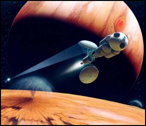
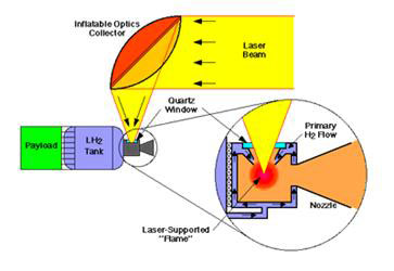
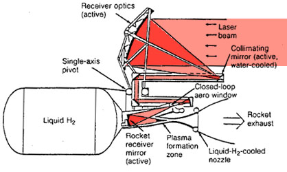

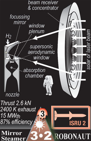

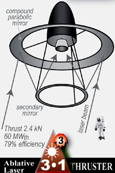


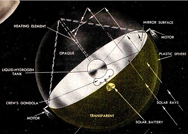
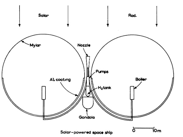
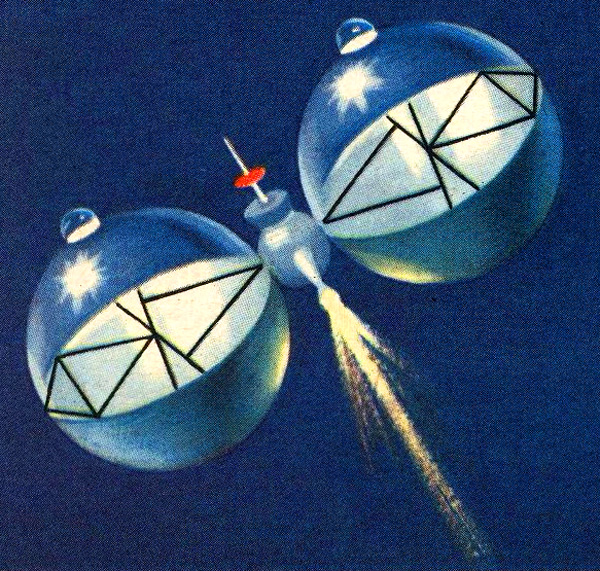

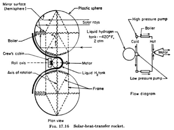


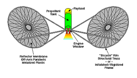

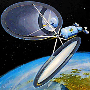
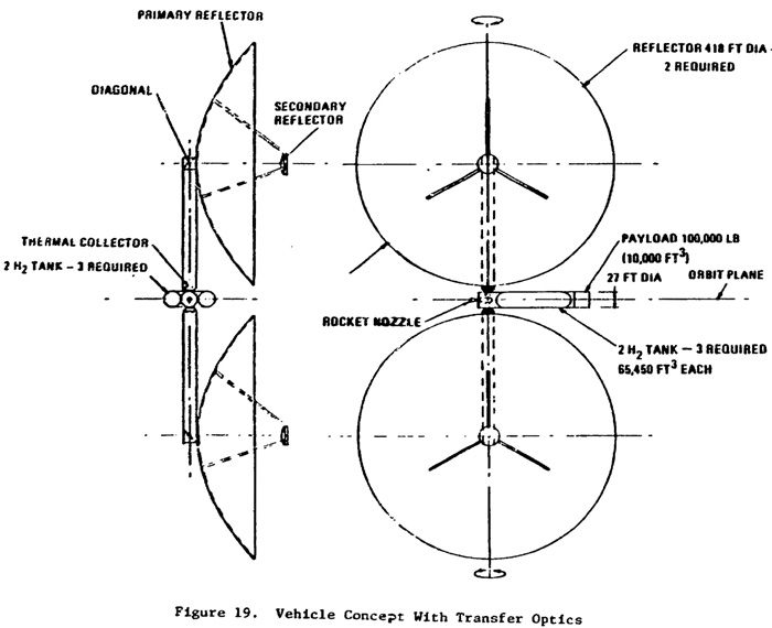
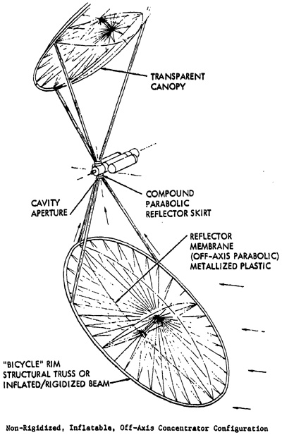

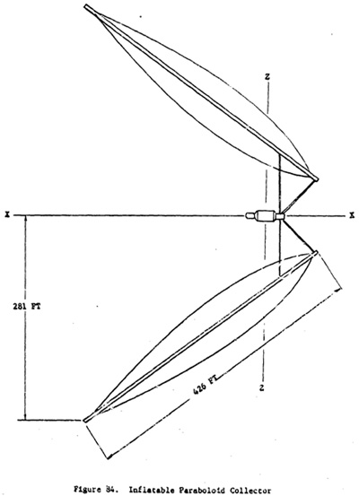
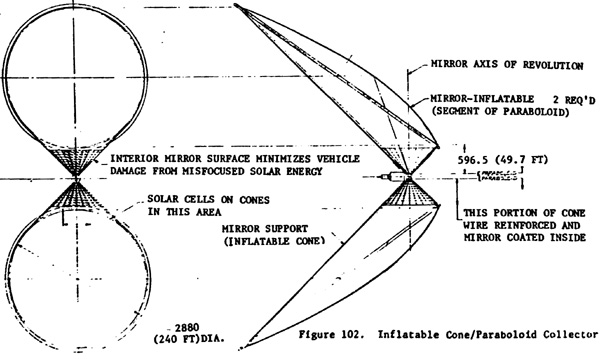


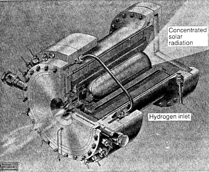
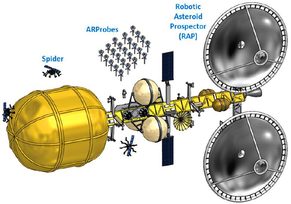


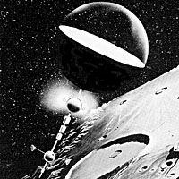
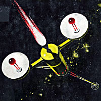
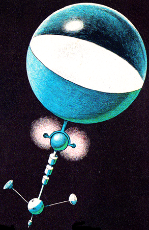
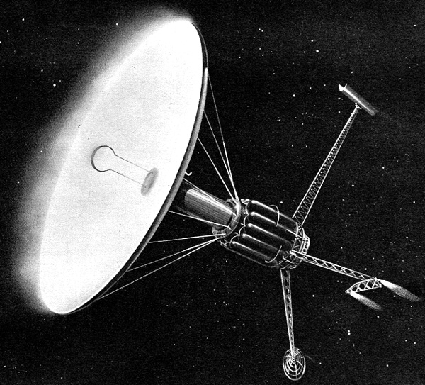
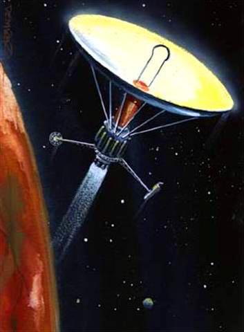

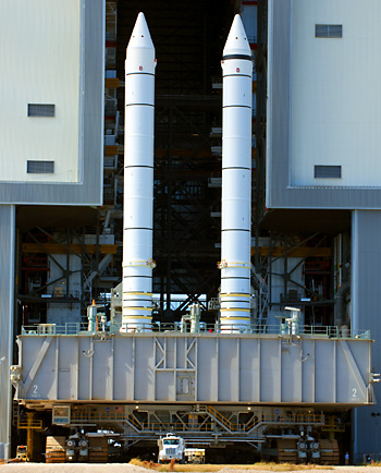
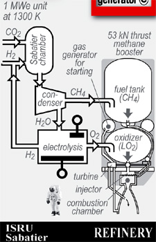

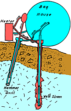
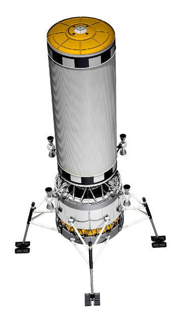
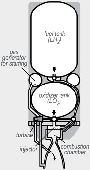
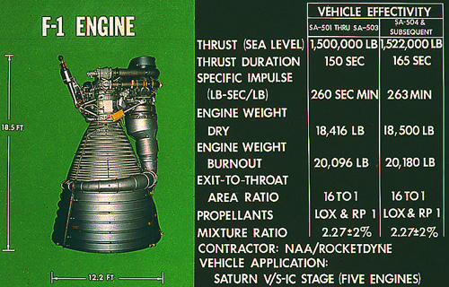
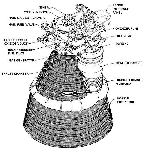
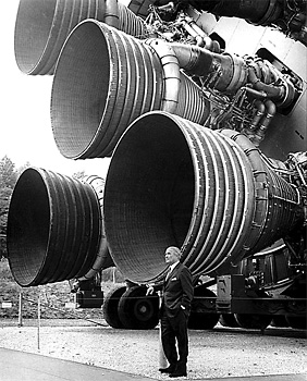
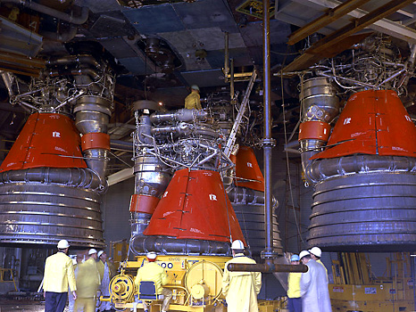
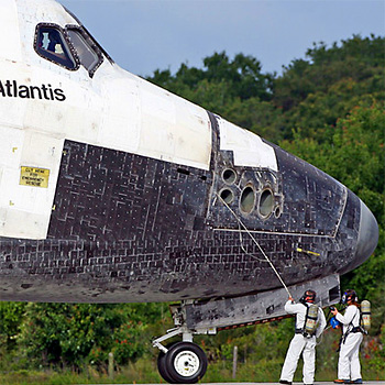
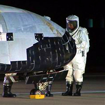
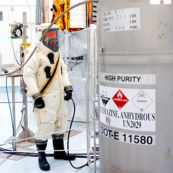
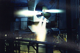
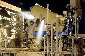
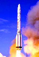


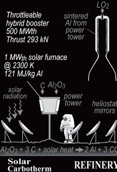
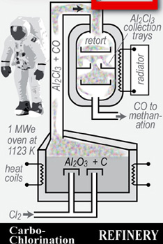
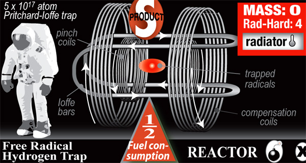
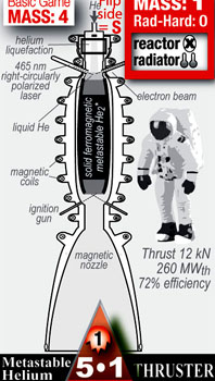
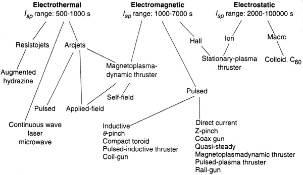

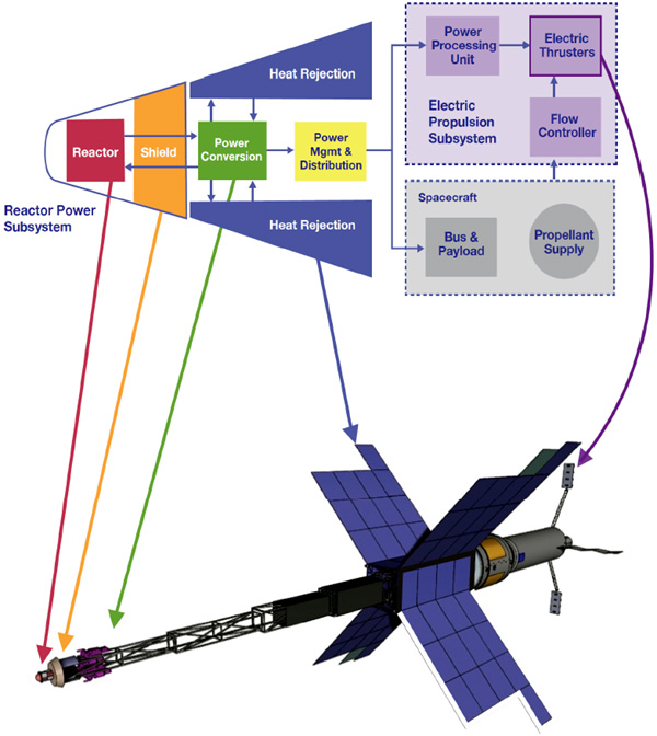
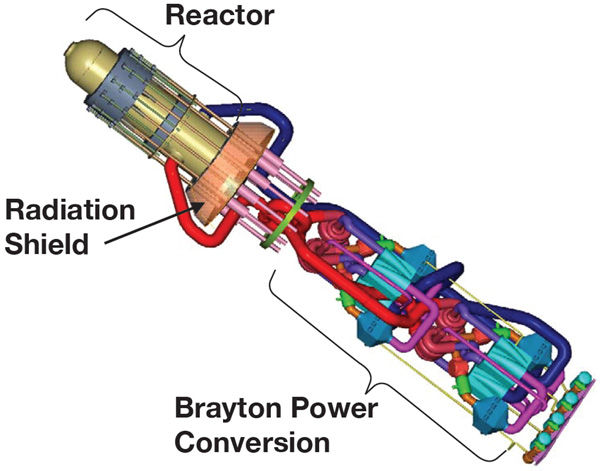
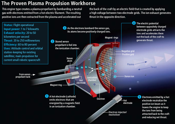
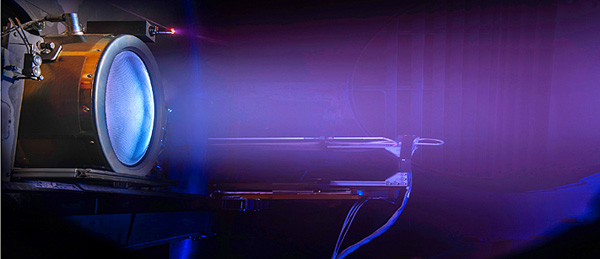
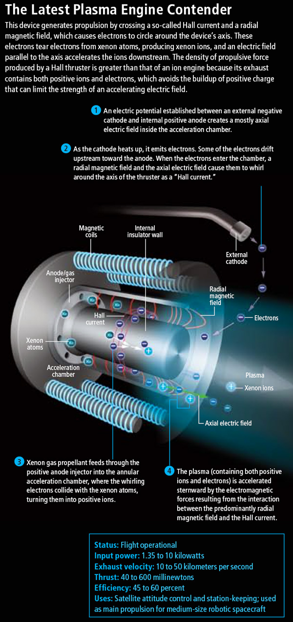
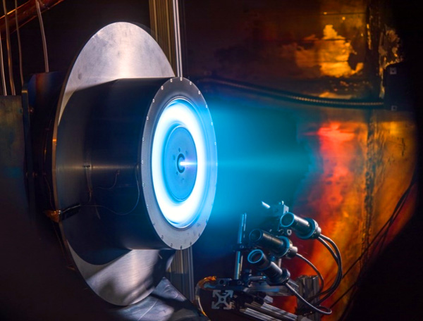
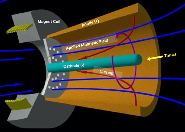
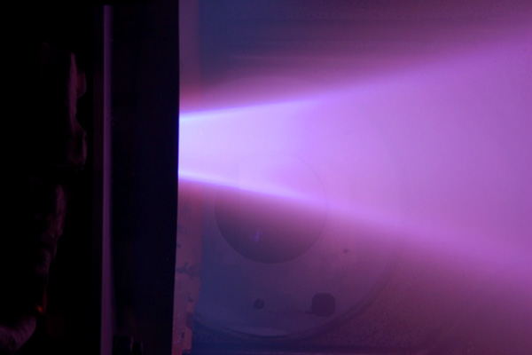
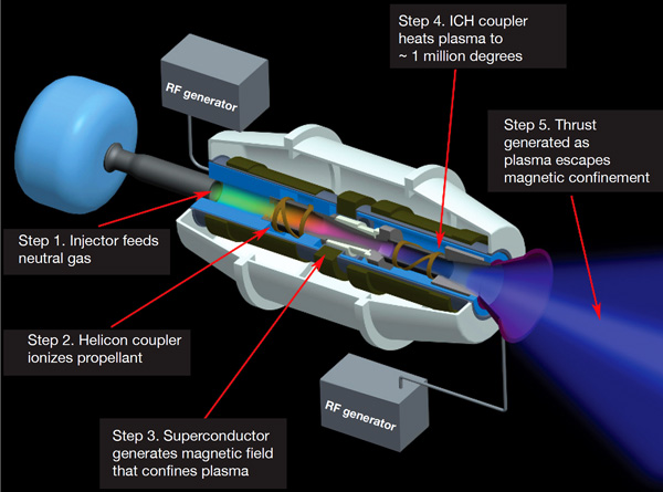
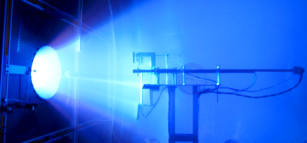
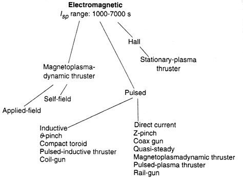
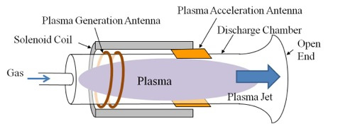
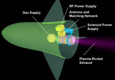
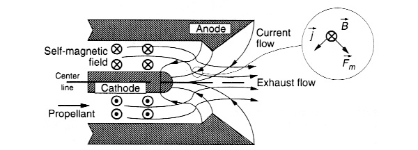

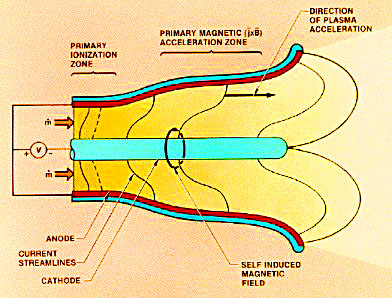
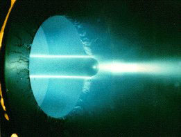
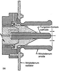
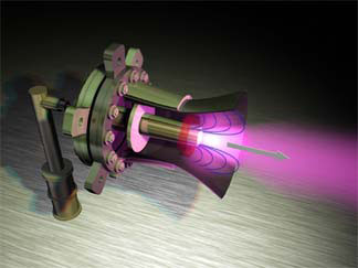
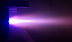
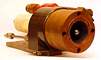
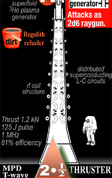
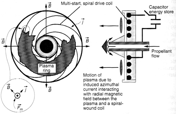
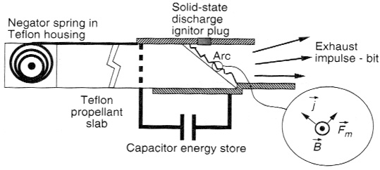
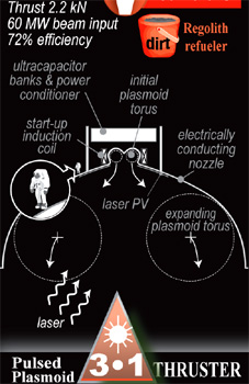

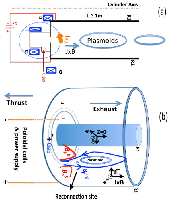
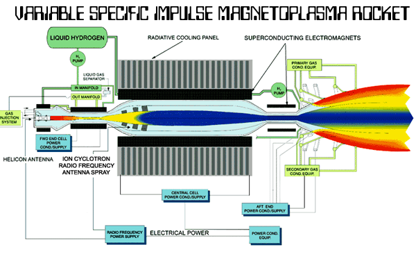
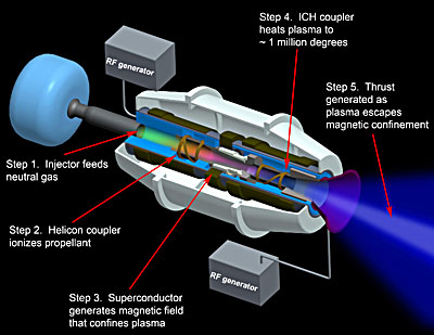
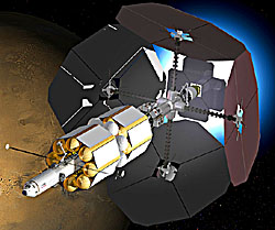
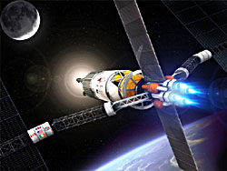
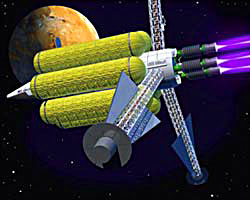
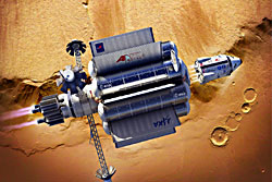
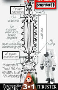
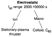


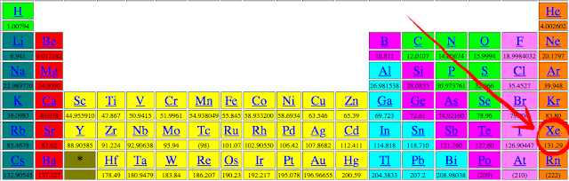
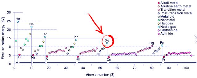
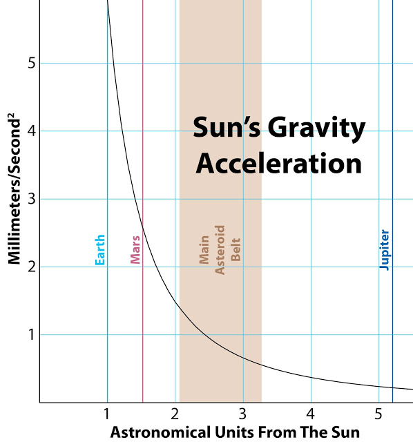
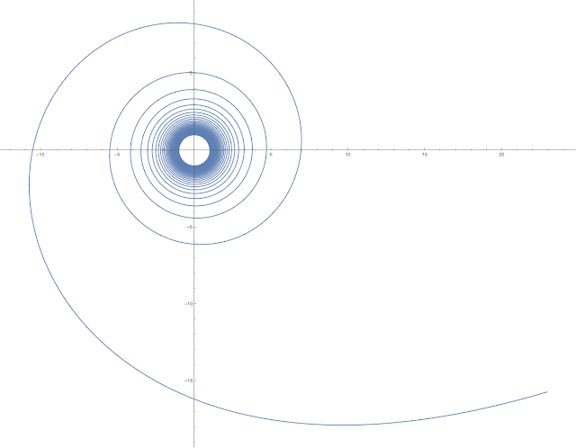
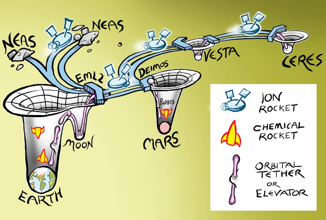

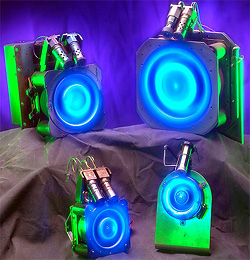
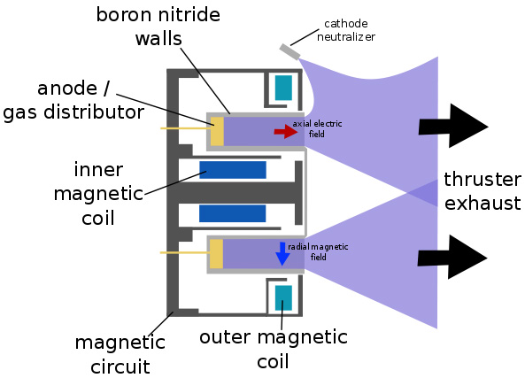
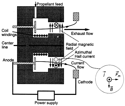
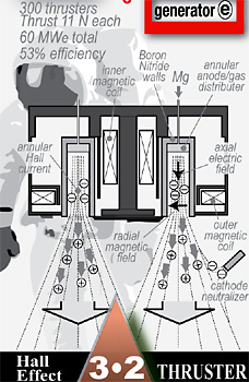
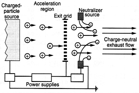
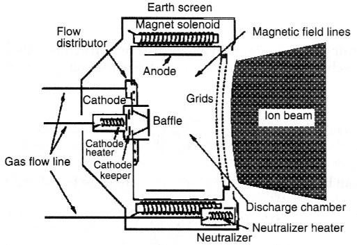
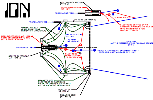


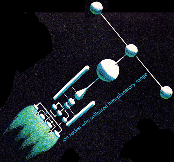
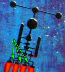
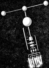


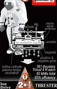
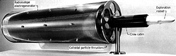
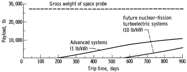
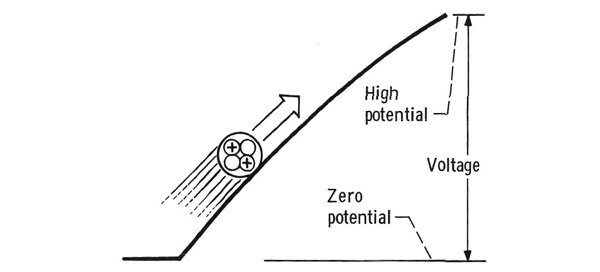
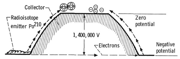
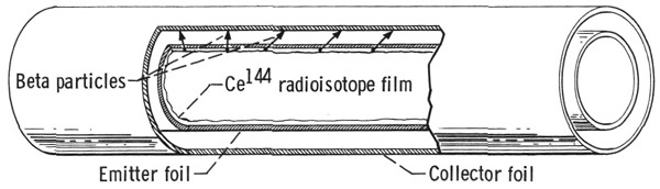

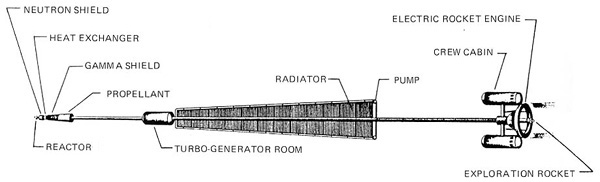


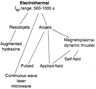
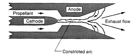
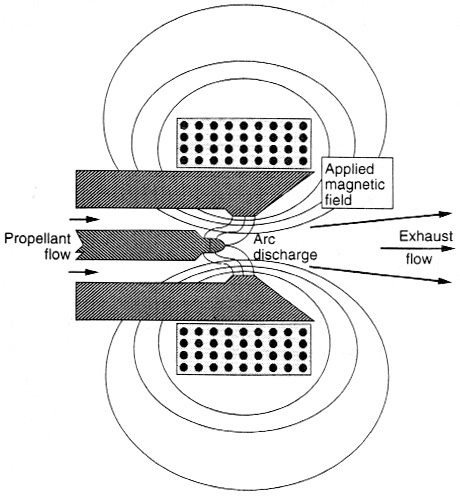
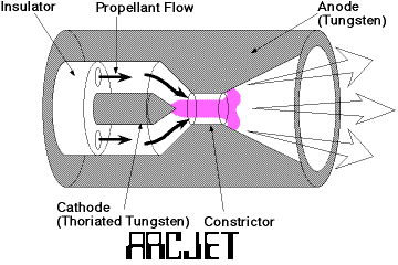
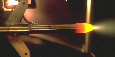
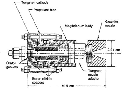
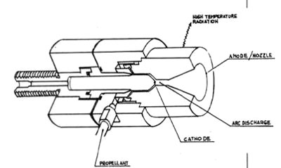
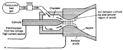
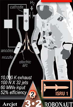
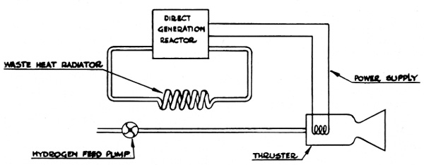
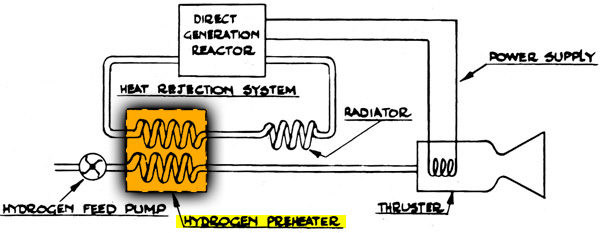
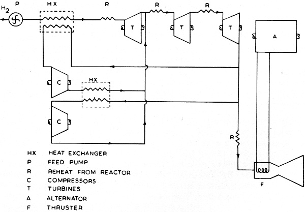
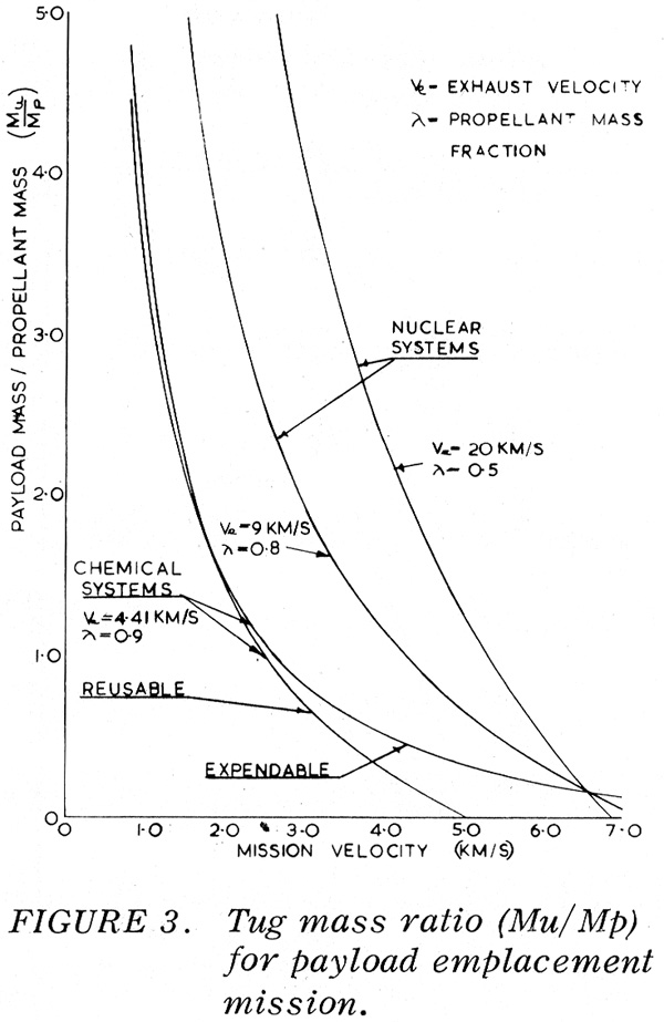
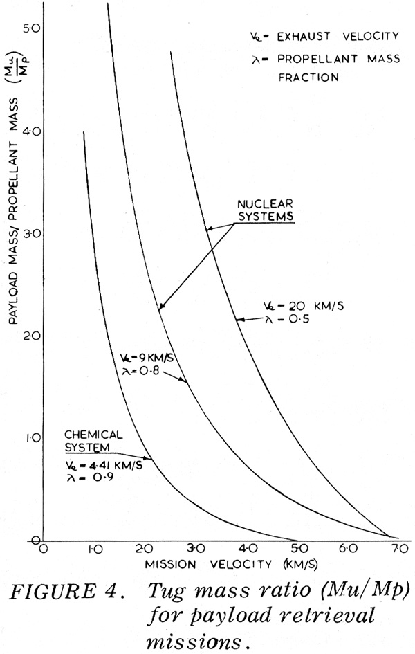
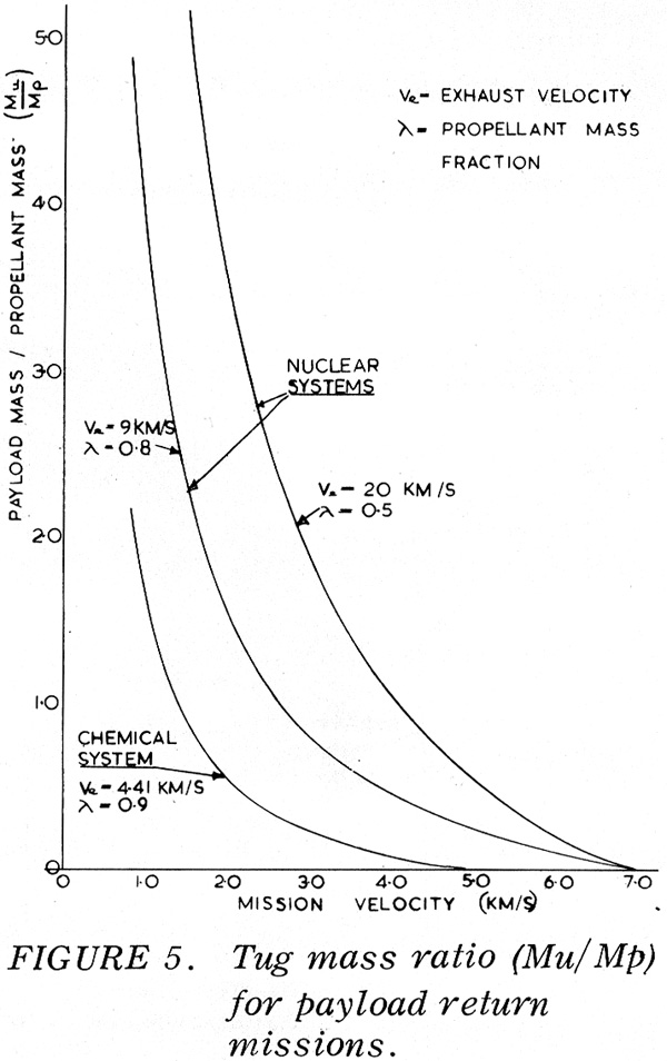
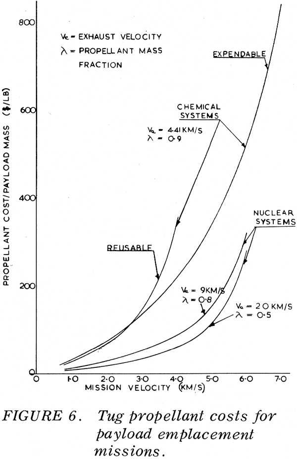
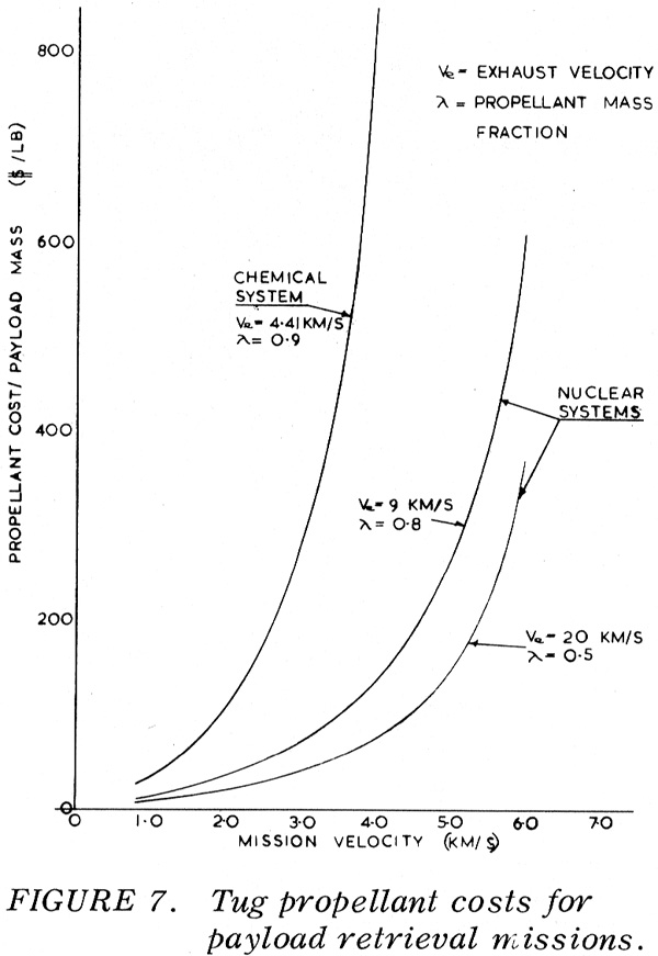
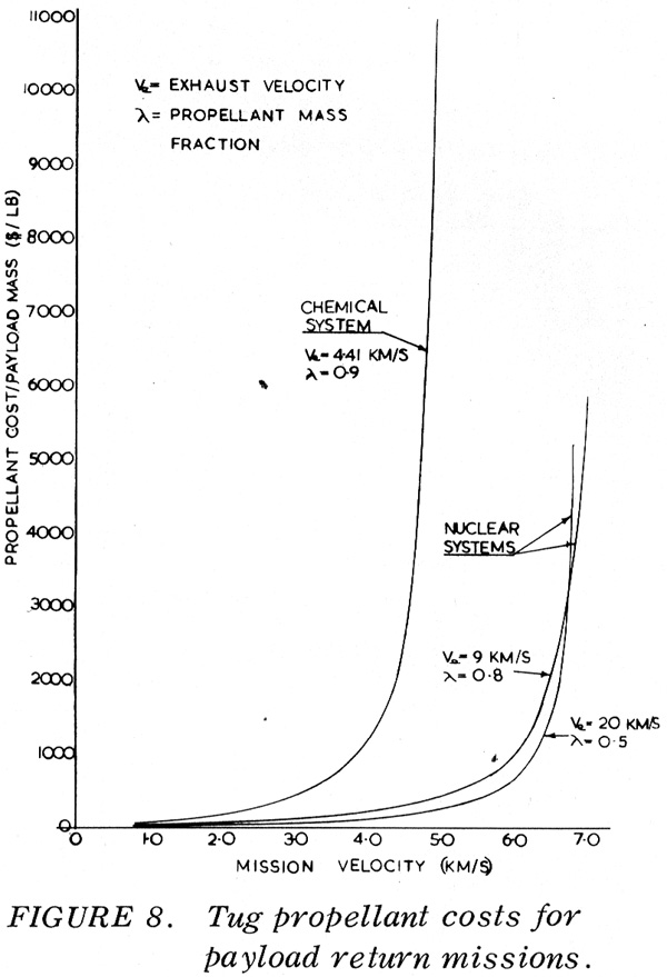
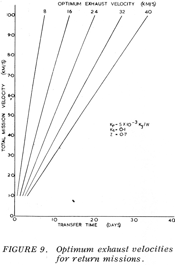
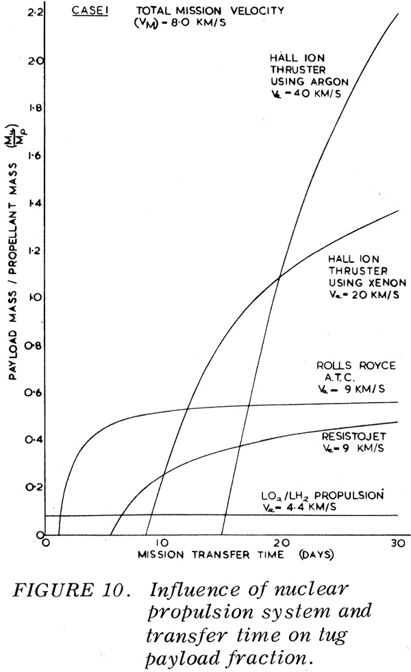
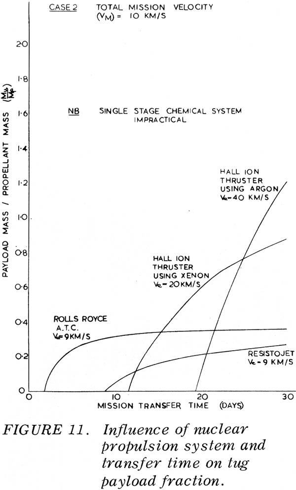
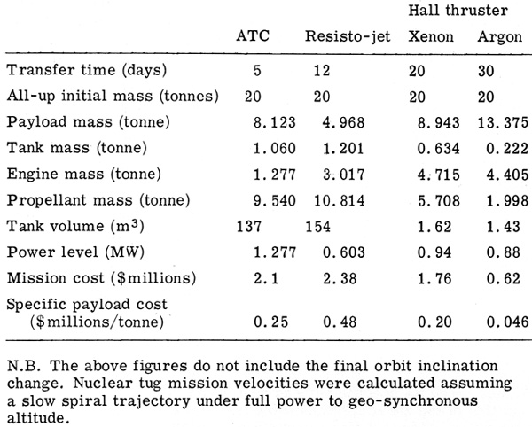
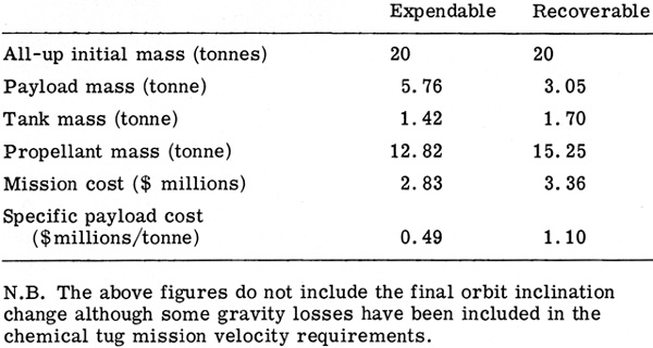
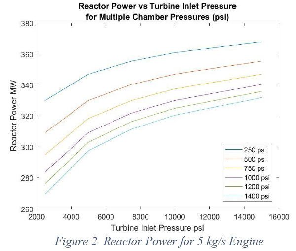
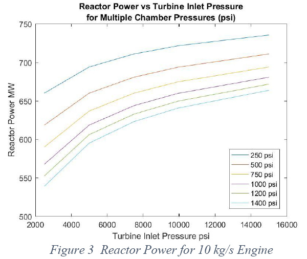
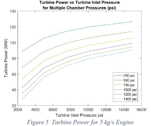
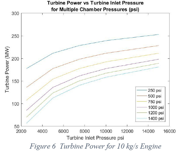
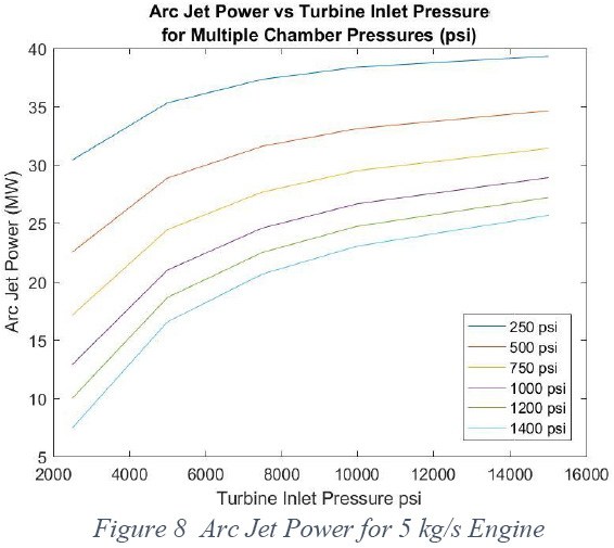
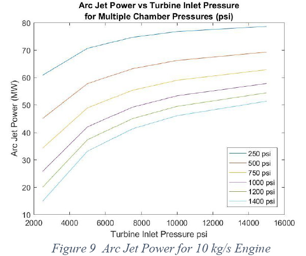
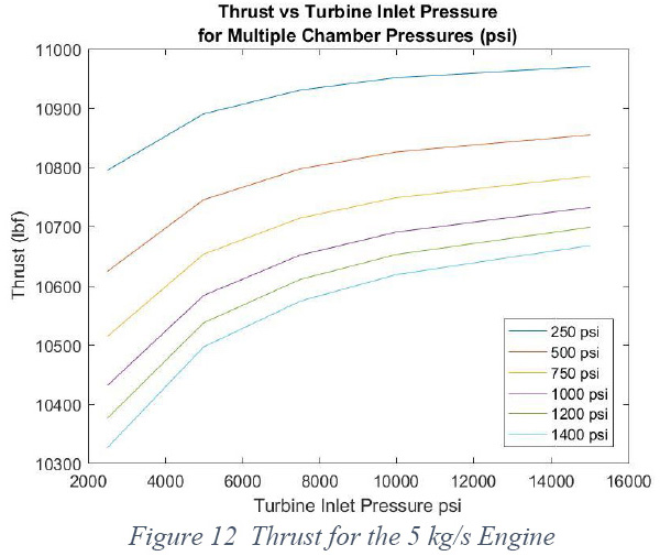
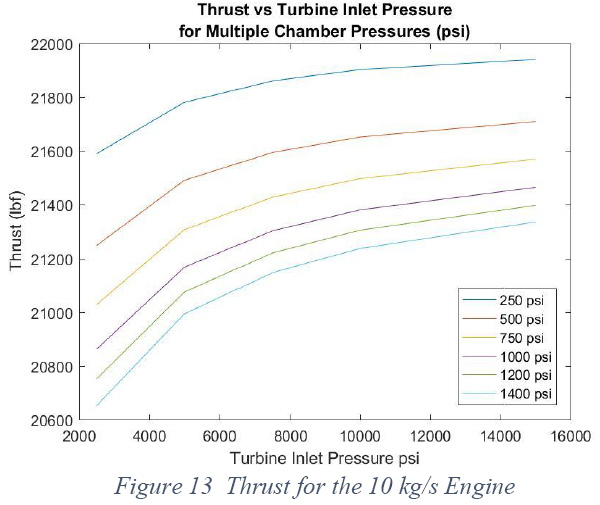
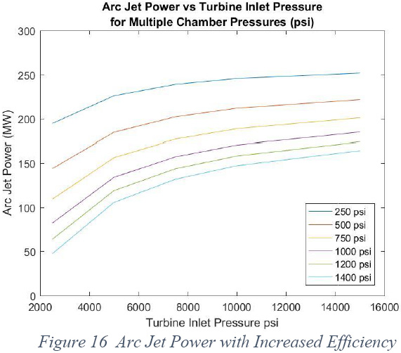
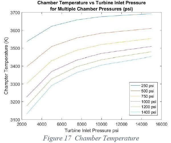
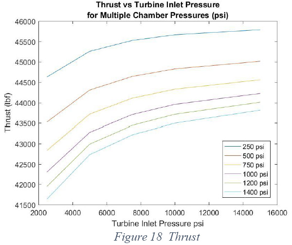
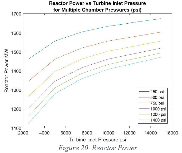
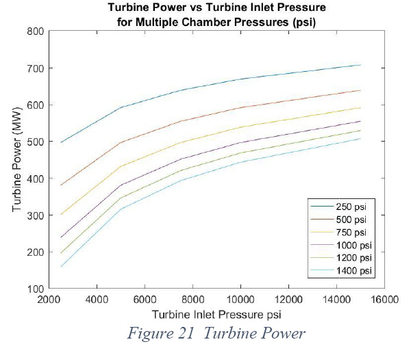
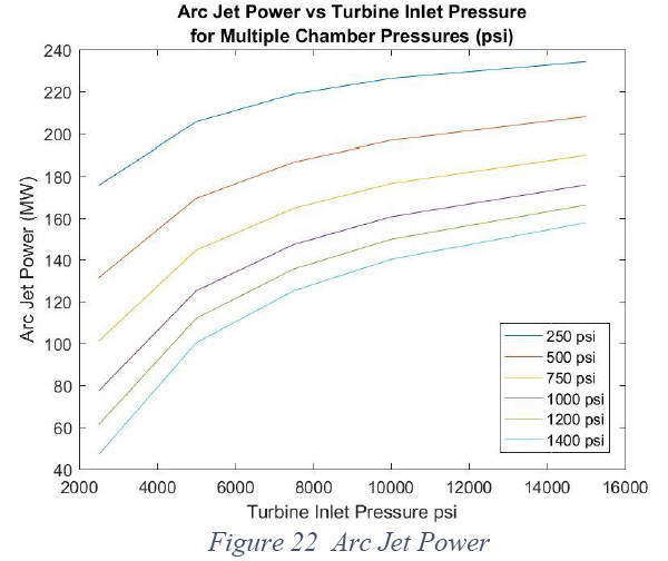
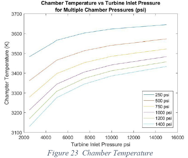
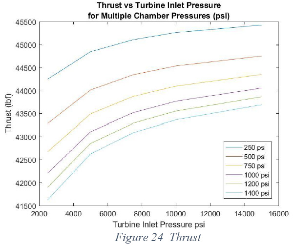
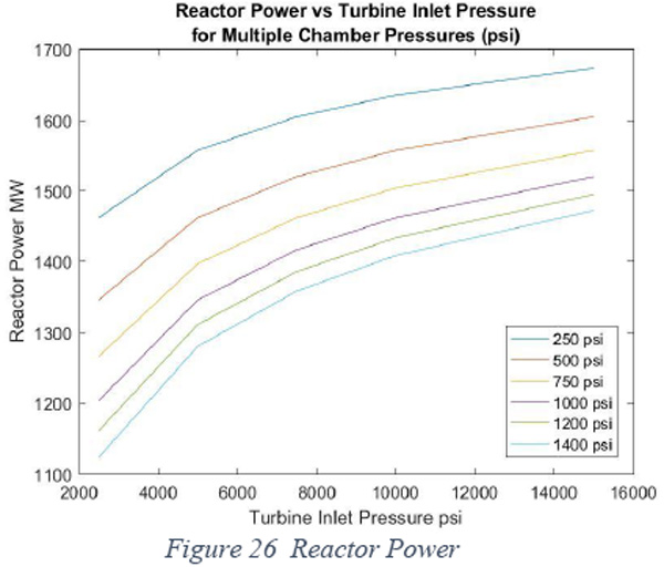
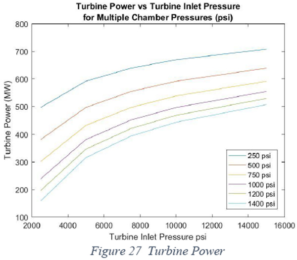
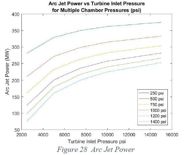
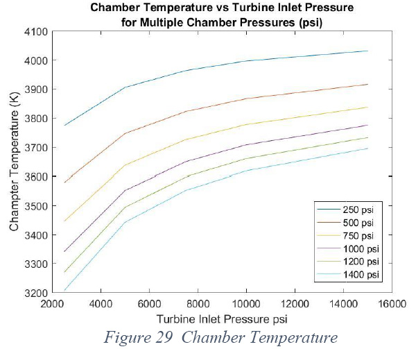
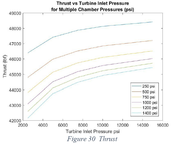
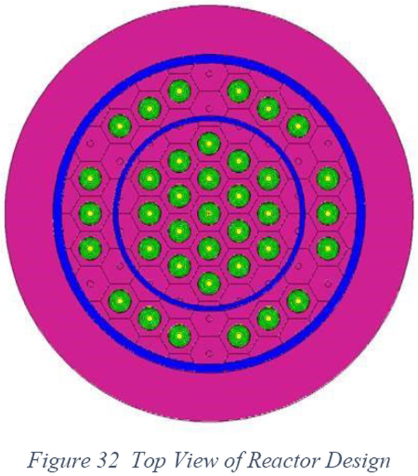
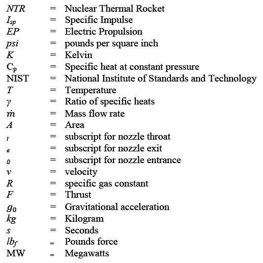
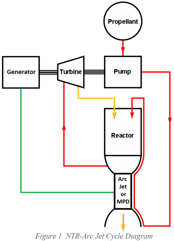
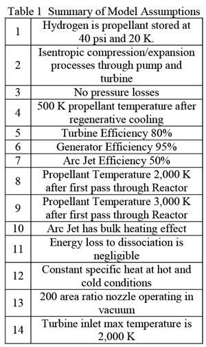
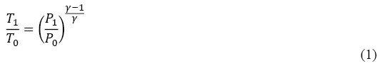
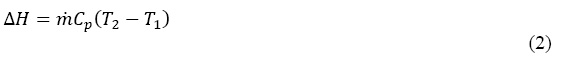
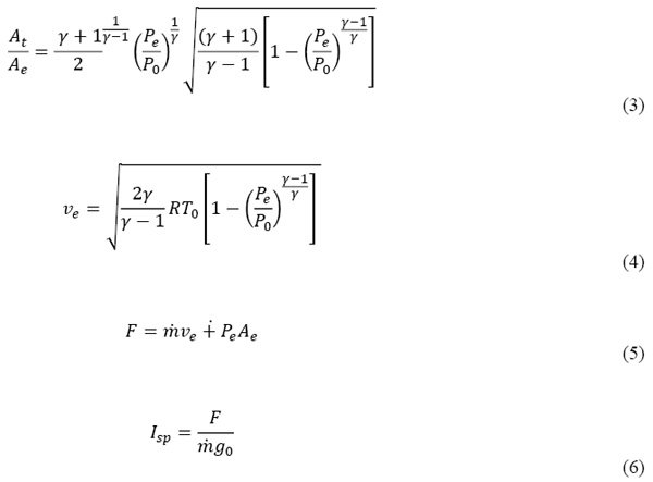
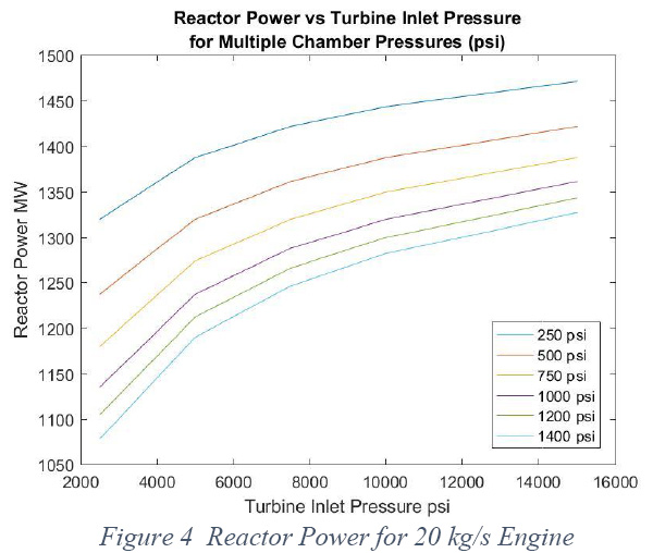
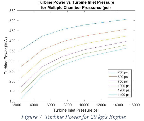
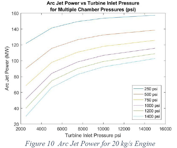
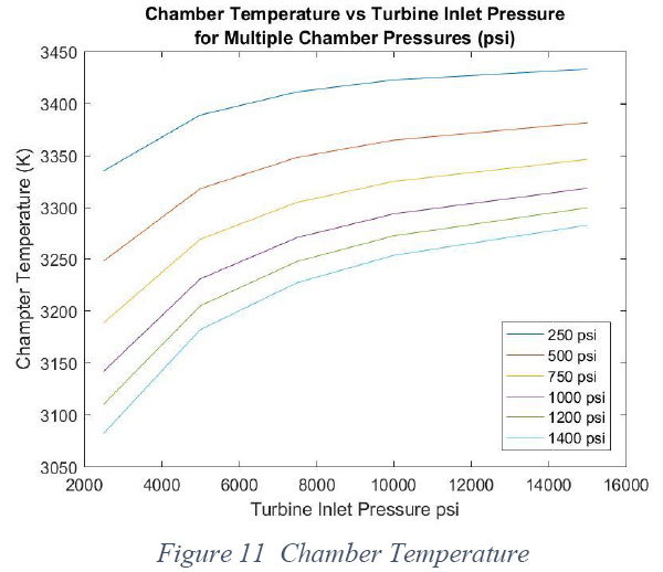
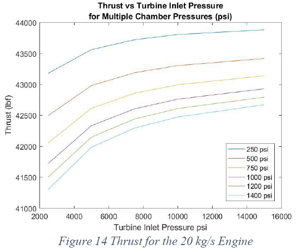
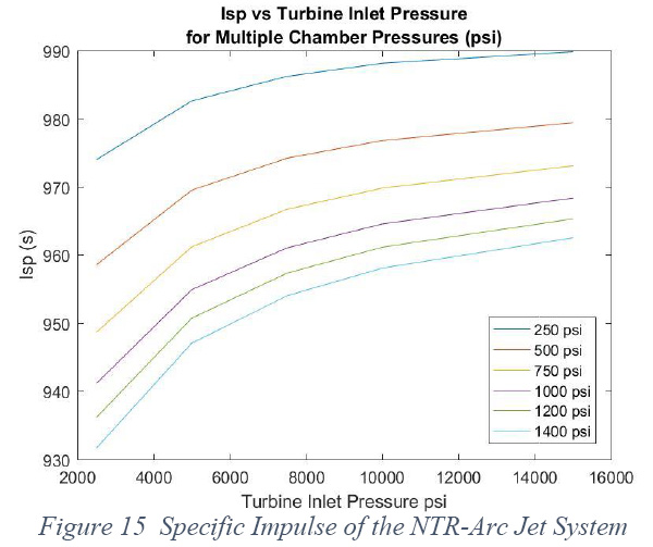
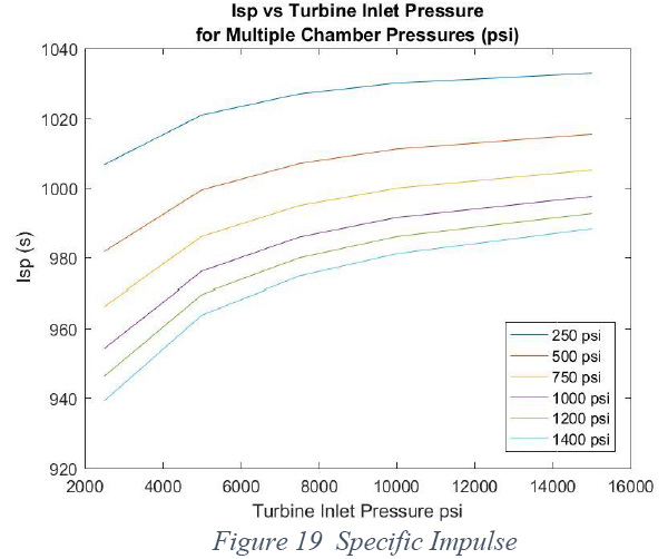
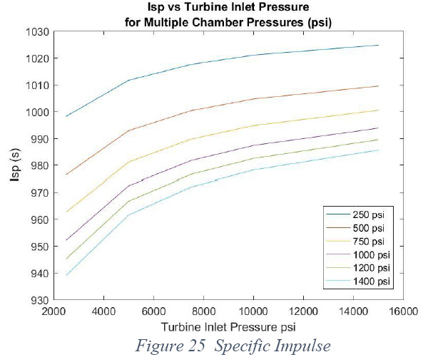
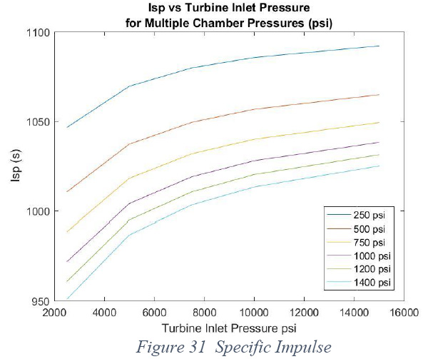
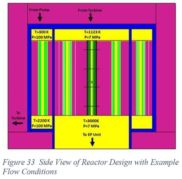
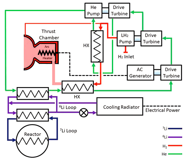


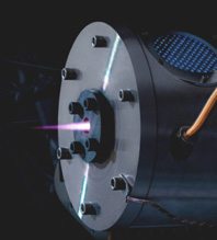
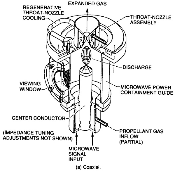
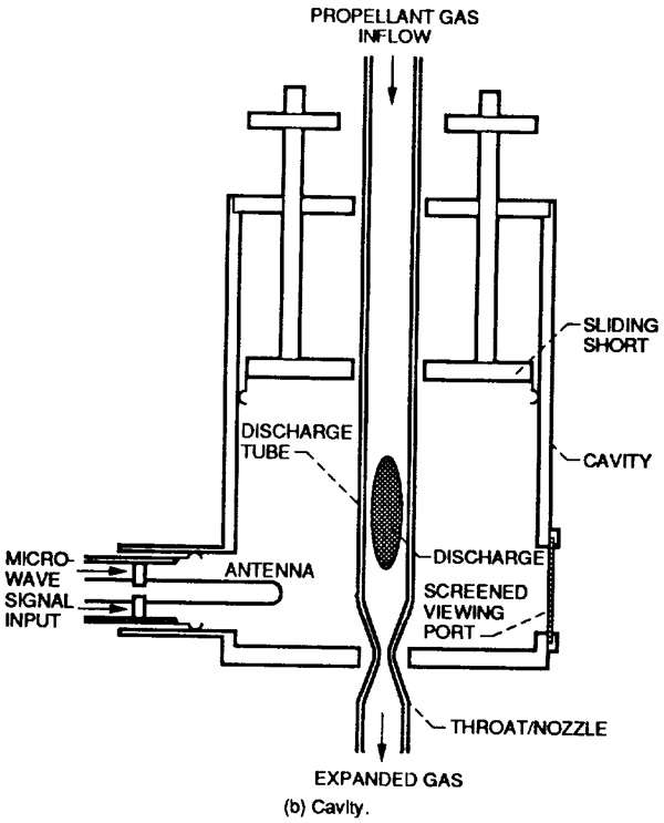
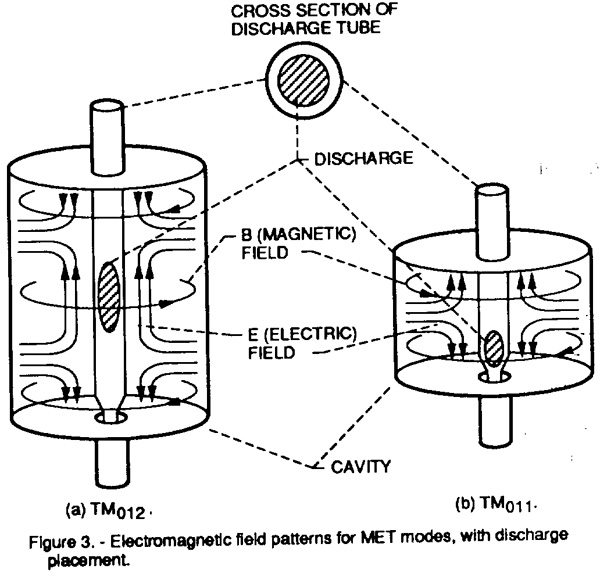
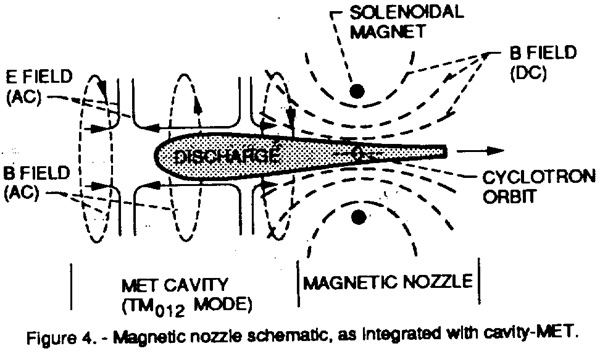
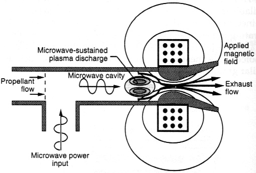
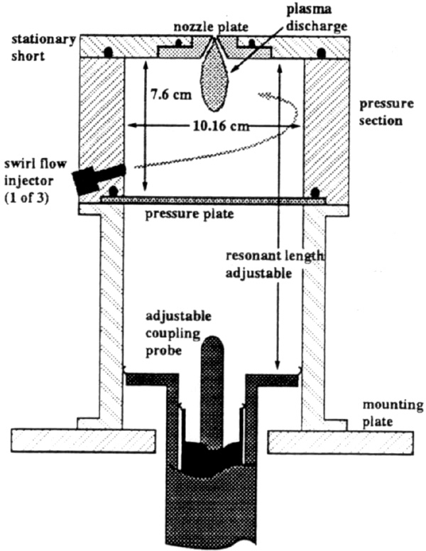
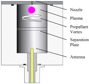
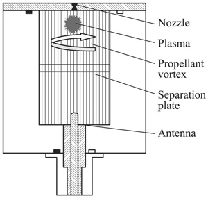
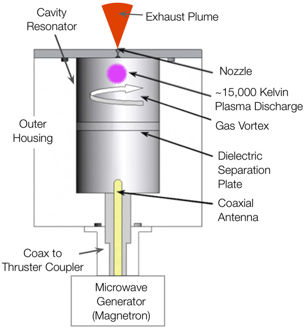
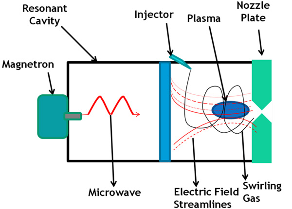
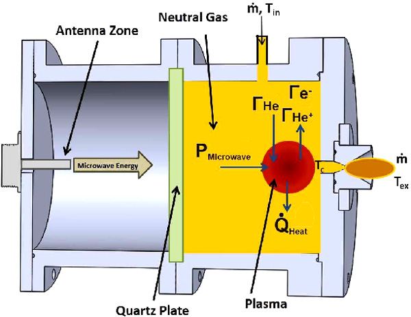
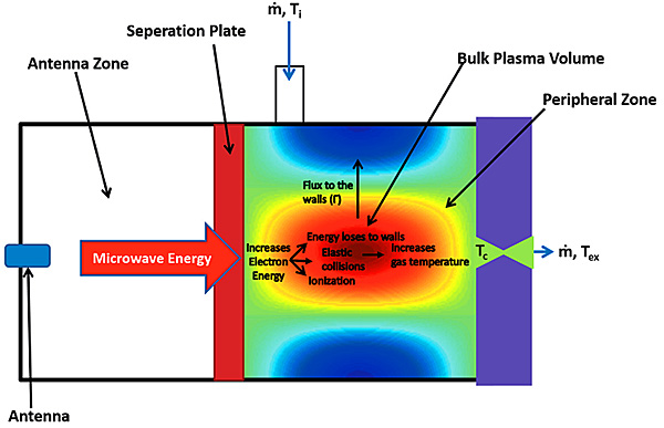
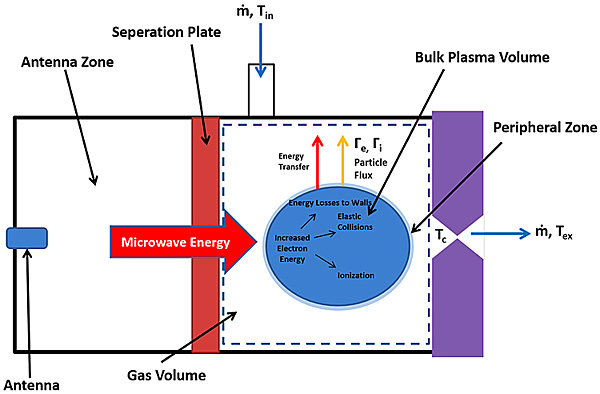
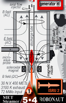

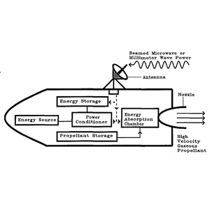
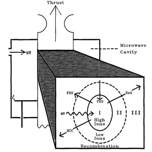
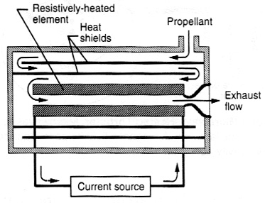
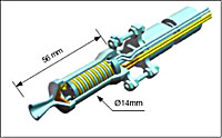
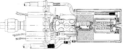
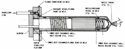
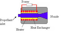
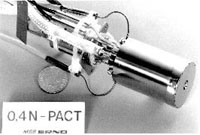
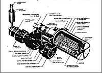
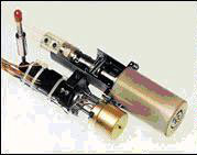

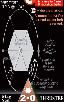

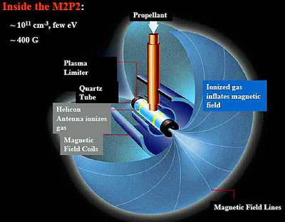
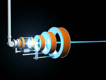
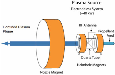
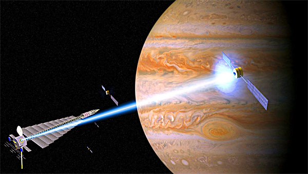
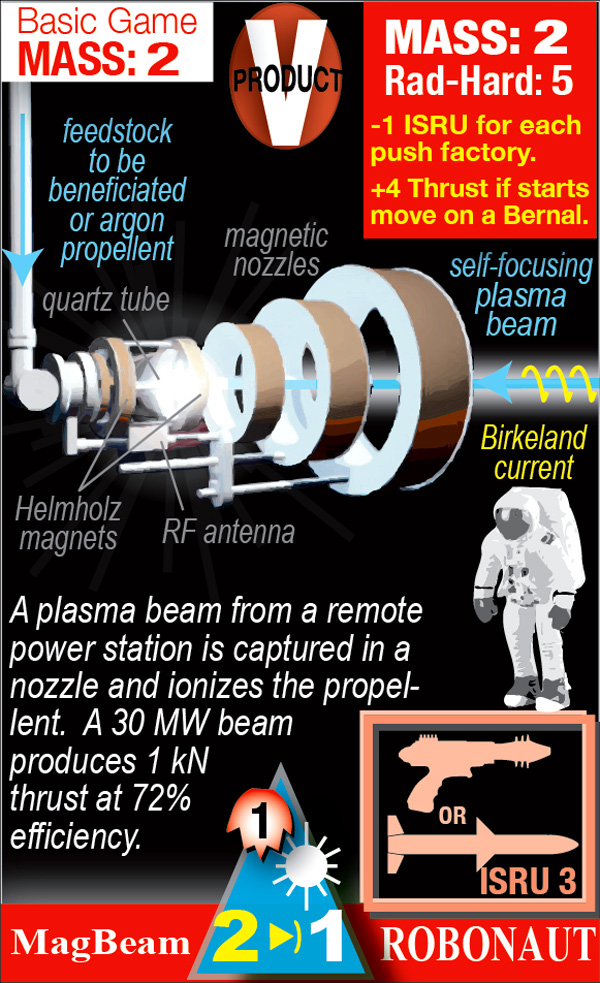


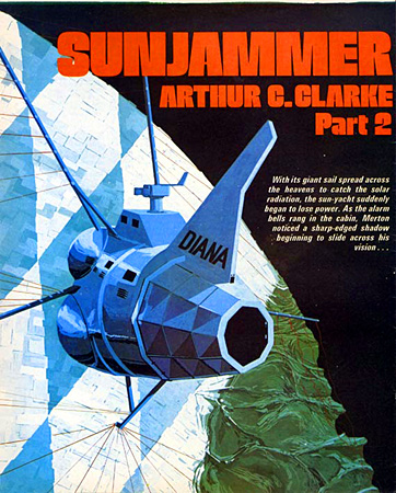
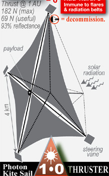
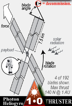

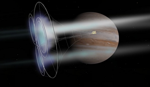
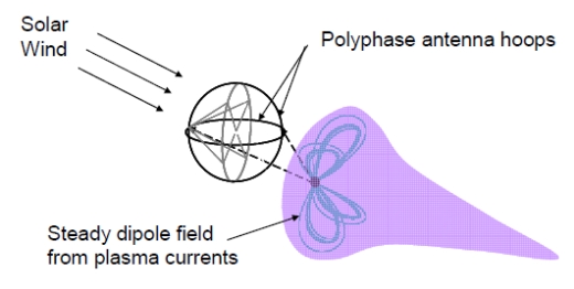
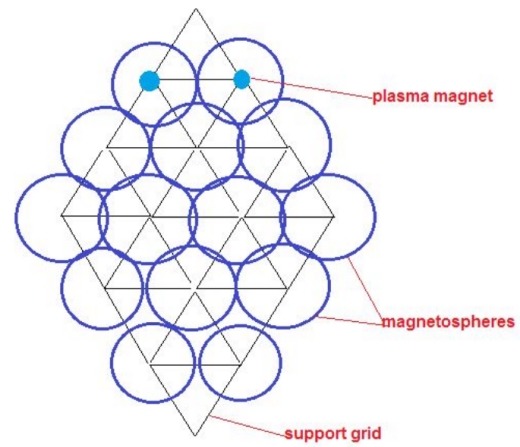
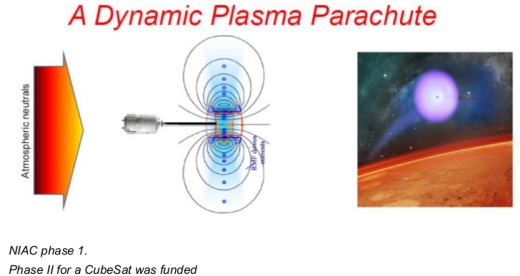
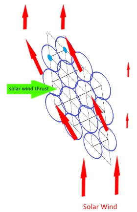


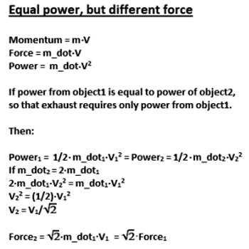
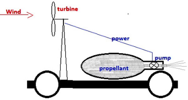
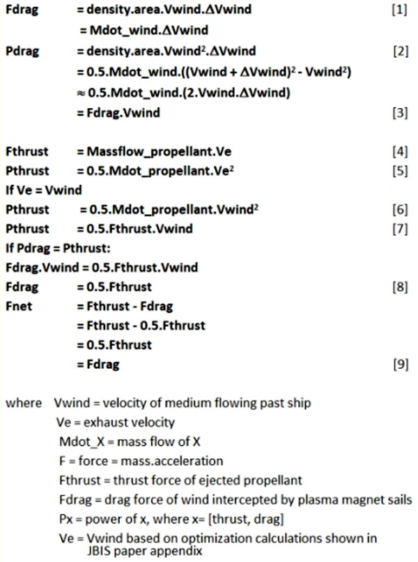
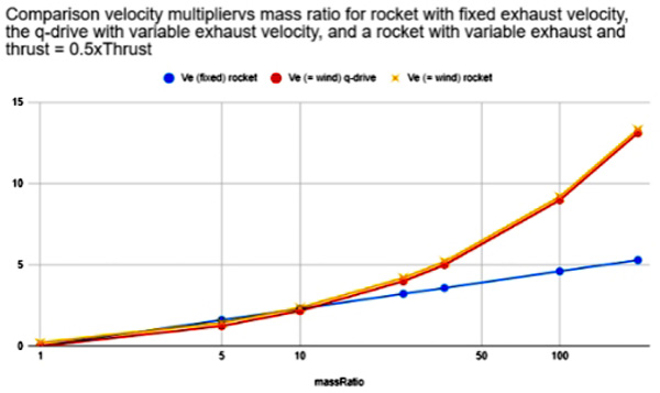
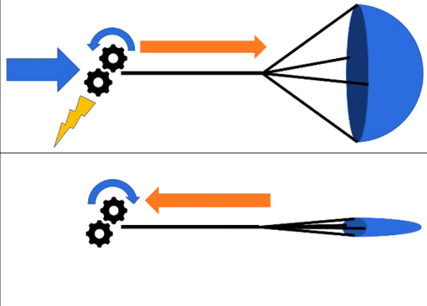
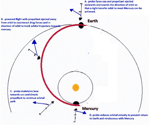
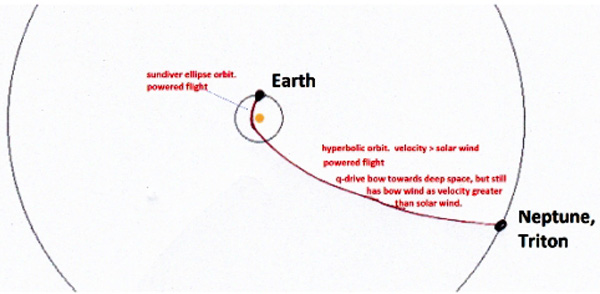
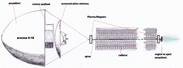
), Equation 3 becomes:
involved at a given phase of flight, differ significantly. As drag devices, they provide thrust as in Equation 1 above, although the power, as shown in Equation 5, is then delivered to the ship rather than being provided by the ship. Power can be large in cases where
is large.
), the scaling is more favorable for the q-drive. Second, mass ratio for a q-drive scales with the square of velocity rather than with the exponential of velocity as in a rocket. Third, in cases where Δv is much less than v∞(initial), as in most flight in the solar system due to the high velocity solar wind, the required mass ratio is even smaller (bearing in mind that the q-drive principle is only useful in situations where v∞(initial)>>0).
of 600km/s, using the q-drive principle with a mass ratio of 16 gives a final velocity of 2400 km/s. This rather startling velocity does not rely on an onboard nuclear reactor or energetic propellant; it is simply the result of momentum and energy exchange with the rest of the medium. The reaction mass is carried away by the surrounding medium and is at rest with respect to it, so the kinetic energy of the initial high-mass ship plus reaction mass has been concentrated into a final, low-mass ship at much higher velocity. It is worth noting that use of drag devices such as the Plasma Magnet sail purely in a drag configuration can produce heliocentric velocities of this magnitude, and that the abrupt deceleration of the solar wind in the termination shock at the heliopause then means that same heliocentric velocity, which tended towards
). While existing electric thrusters operating at ~4x10⁵ m/s exhaust velocity are immature, they are plausible under known physical principles. The expelled reaction mass ends up nearly at rest with respect to the solar wind, while the ship accelerates sunward (or reduces its outward velocity).
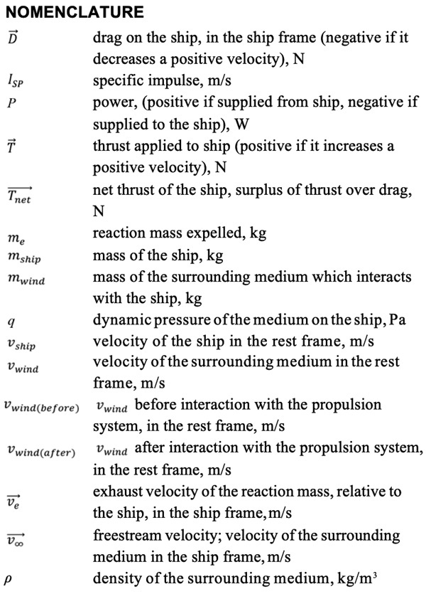
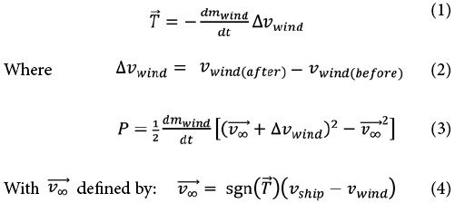

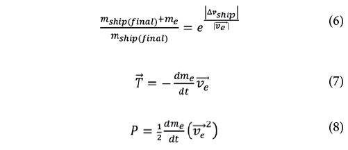
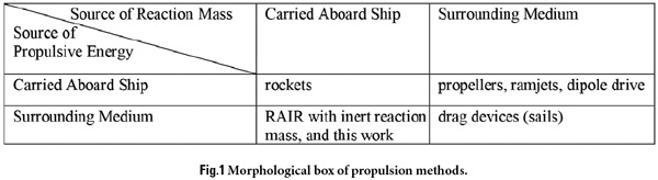
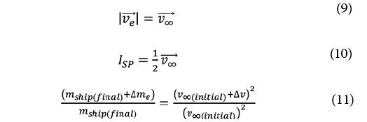
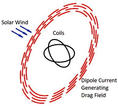
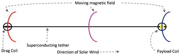

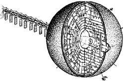


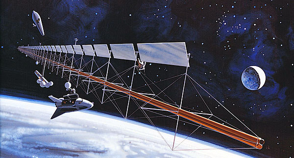
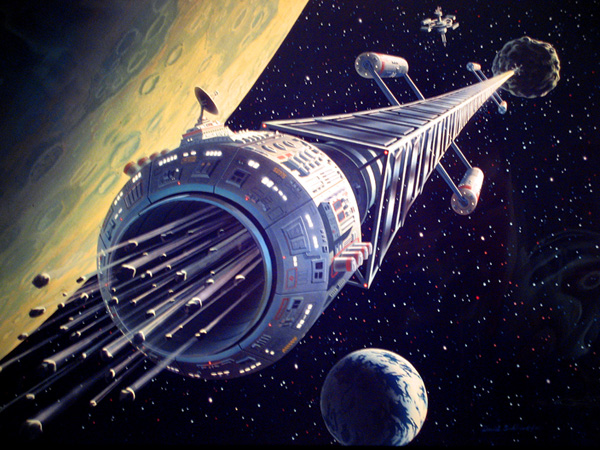

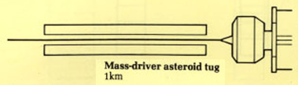


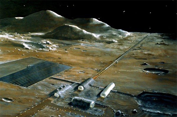
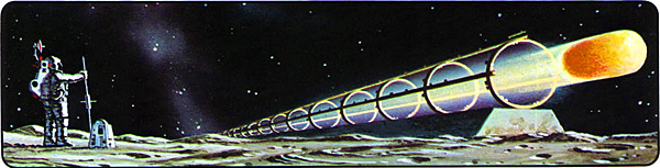
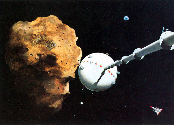
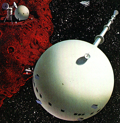
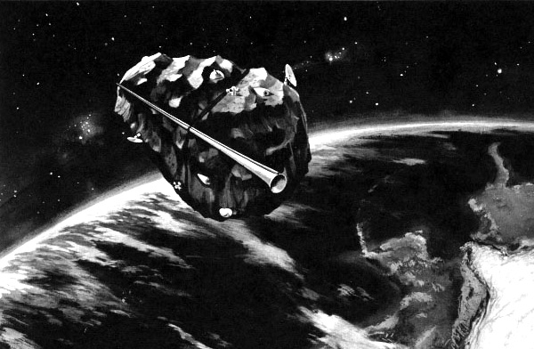
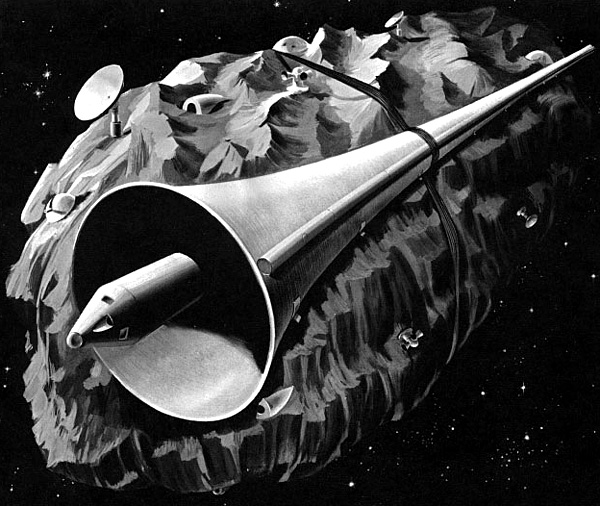

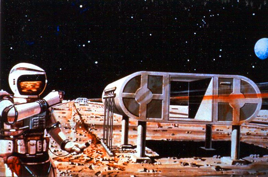

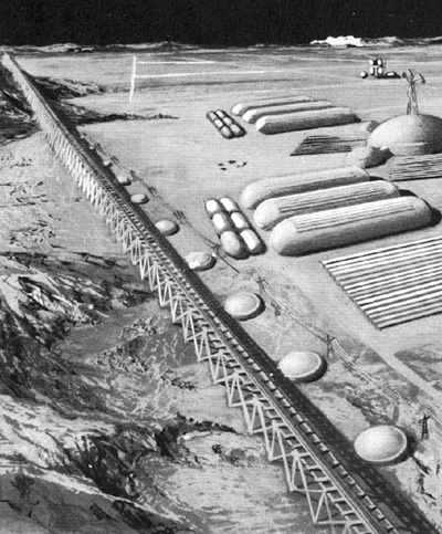
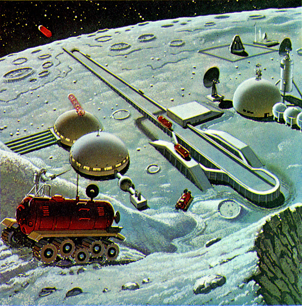
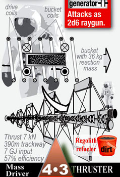


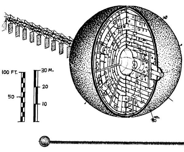
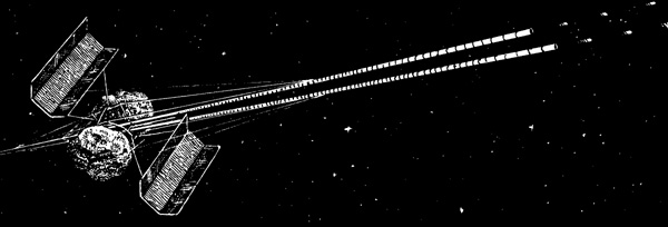
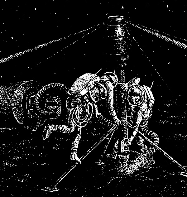
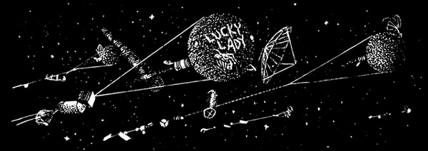
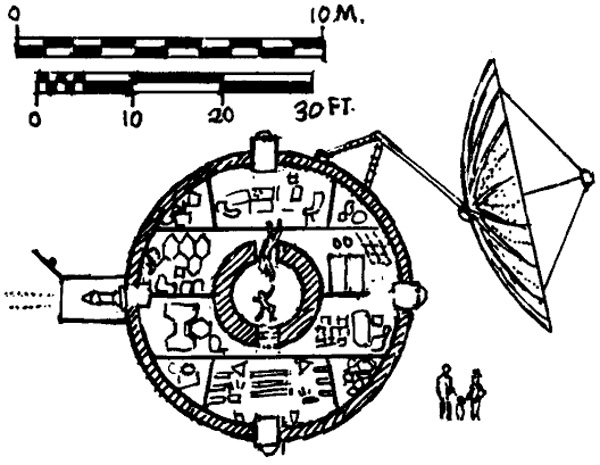


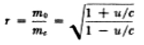
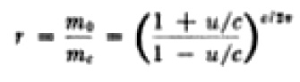
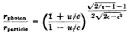

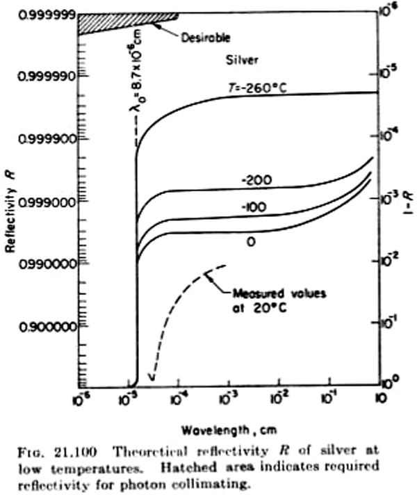
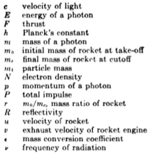
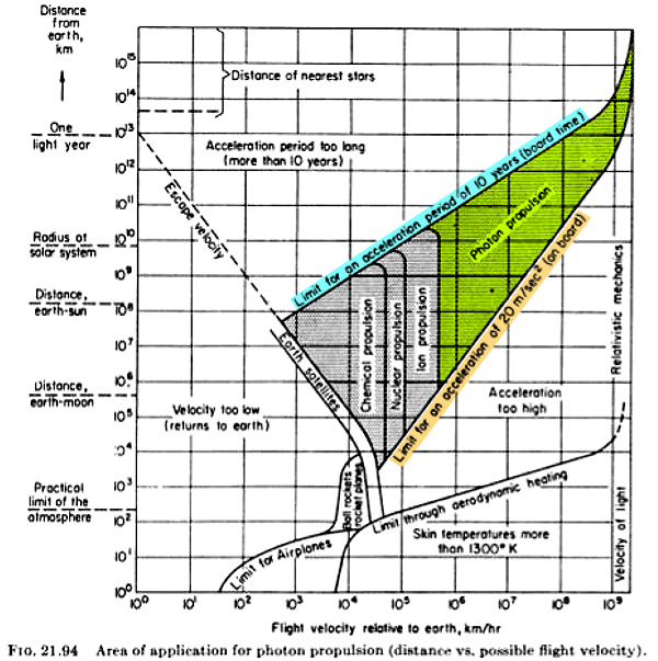
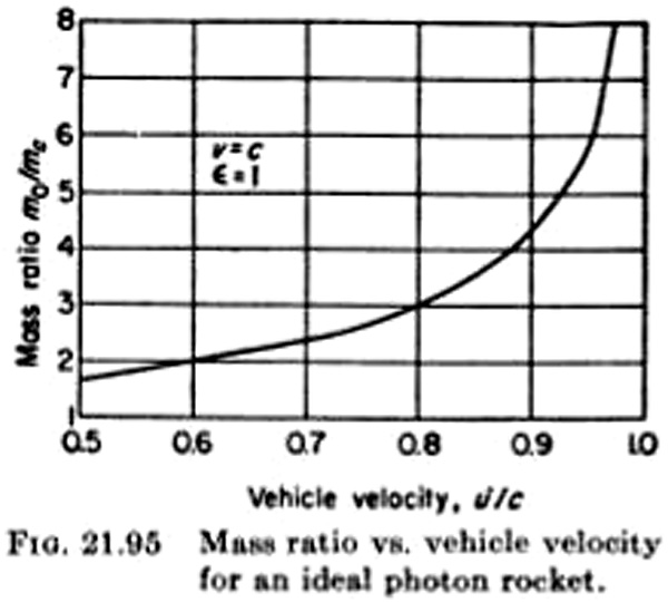
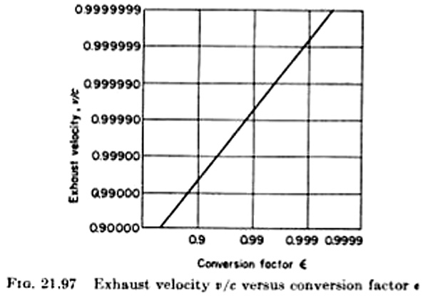
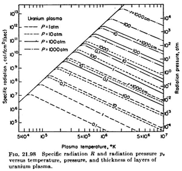
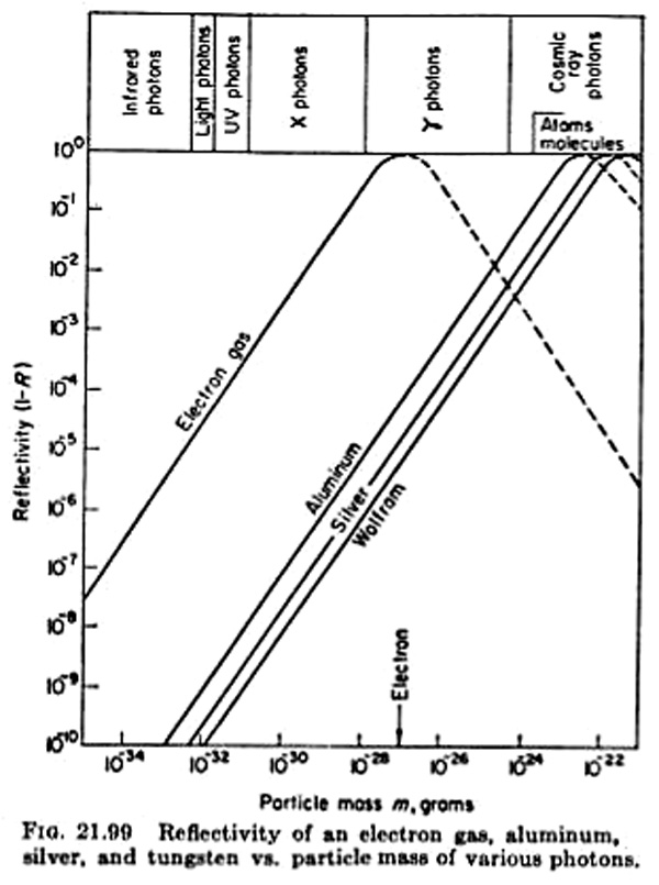
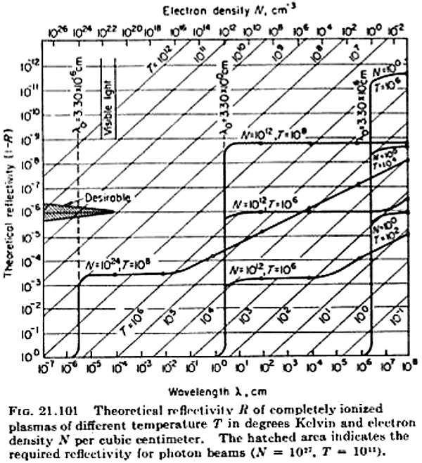
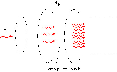
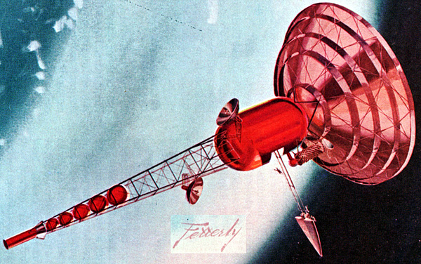
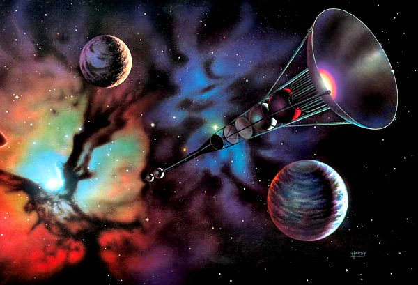
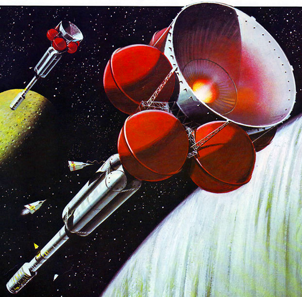
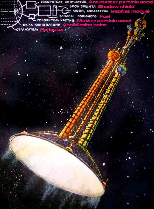
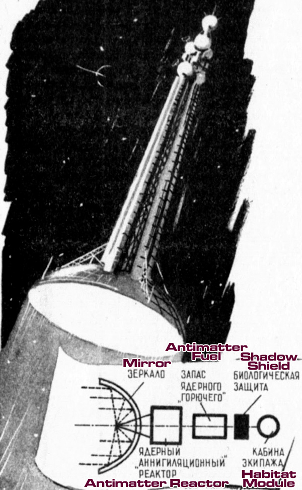
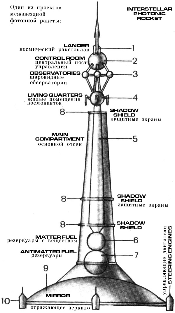
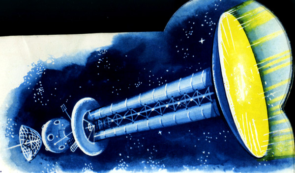
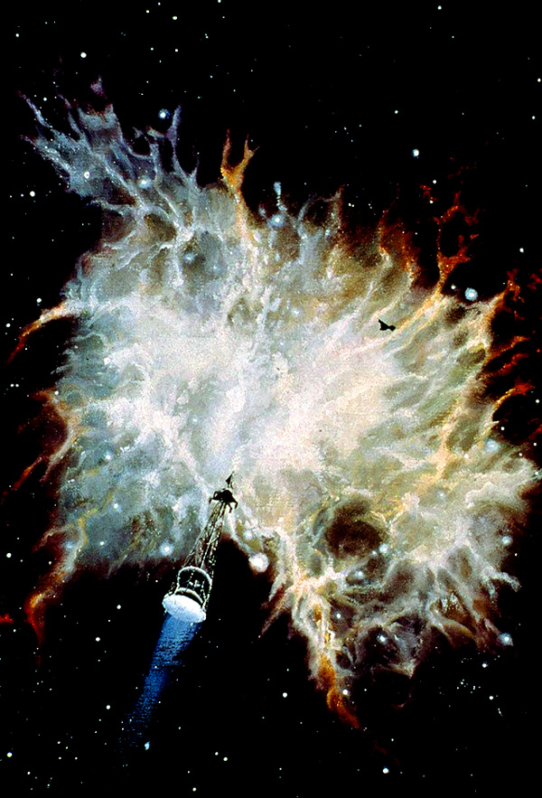

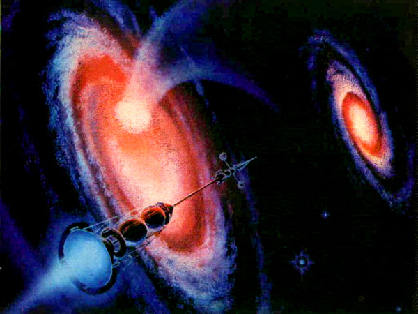
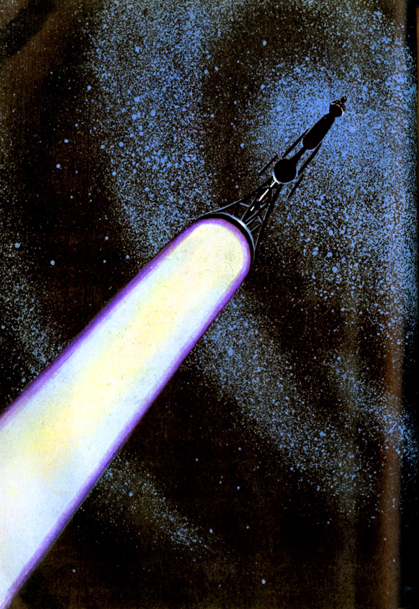
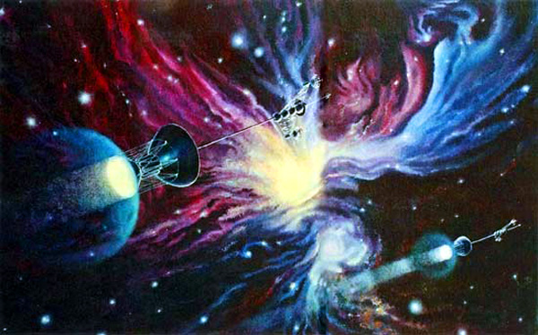
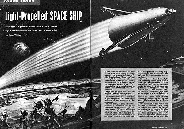
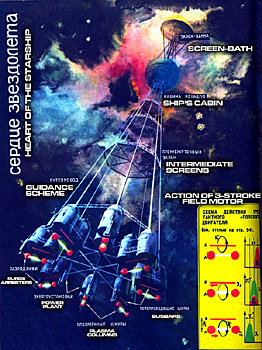
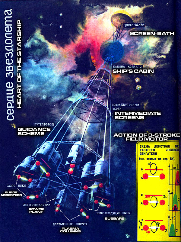

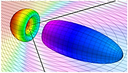
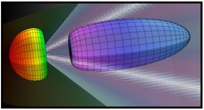


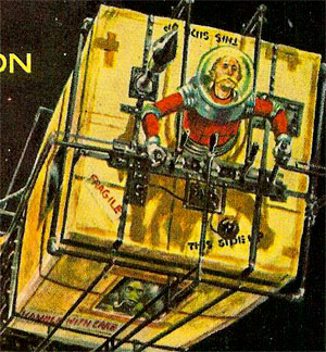
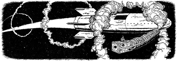
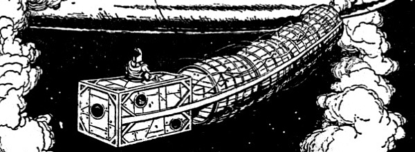

