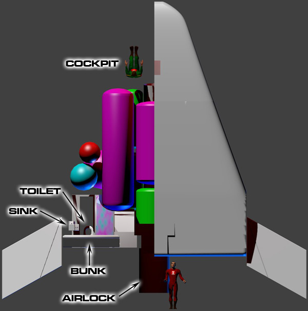
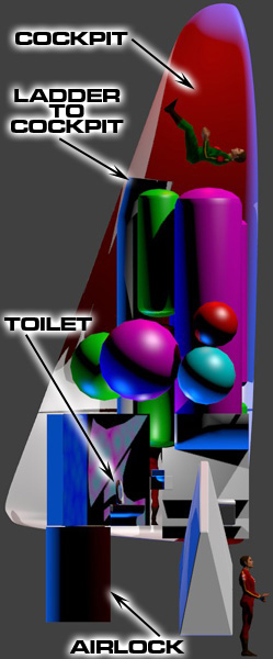
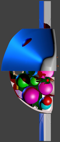
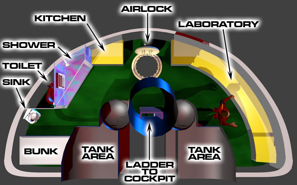
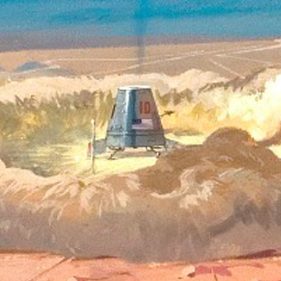
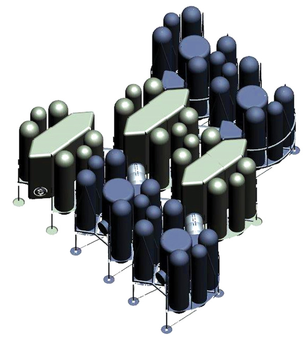
10-Crew Ceres-Vesta PEM Visualization by master artist William Black
Introduction
Assuming your spacecraft is not a freaking torchship, a Mars expedition with the entire spacecraft landing then lifting off is going to demand about ten times as much delta V than it has to spend. This is why pretty much all NASA designed crewed Mars missions have the main spacecraft loiter in orbit while the explorers use a tiny Mars Excursion Vehicle (a "lander") to ferry them to and from the surface.
The landers here assume that the planet they are visiting are wilderness worlds, that is, they do not have local starports equipped with booster rockets or anything like that. A couple of Mars expedition designs try to edge around that. They have prior unmanned missions to land robot factories utilizing the Sabatier reaction that manufacture rocket fuel from the Martian atmosphere. This wonderfully lowers the delta-V requirements.
The Lunar landers listed here will also probably work on any airless body in the solar system, with the possible exception of the planet Mercury. That planet has the dubious honor of having the highest orbital velocity of all the airless bodies. This means Mercury is the most delta-V costly world to land/lift-off from. The planets with more gravity than Mercury have an atmosphere suitable for aerobraking, providing free delta-V.
The Mars landers will work on Mars, but no guarantees on them working with any other planet. Most of them require aerobraking, so they only work on planets with atmospheres. And the planets with more gravity than Mars require more delta-V for lift-off than the landers have.
Turning to some science fiction speculation, an exploration starship with a huge on-board power plant might assist their landers. The mothership can use large lasers to send power to the landers to help with landing and lift-off.
THREE SHIP TYPES
The traveling-public gripes at the lack of direct Earth-to-Moon service, but it takes three types of rocket ships and two space-station changes to make a fiddling quarter-million-mile jump for a good reason: Money. The Commerce Commission has set the charges for the present three-stage lift from here to the Moon at thirty dollars a pound. Would direct service be cheaper?
A ship designed to blast off from Earth, make an airless landing on the Moon, return and make an atmosphere landing, would be so cluttered up with heavy special equipment used only once in the trip that it could not show a profit at a thousand dollars a pound! Imagine combining a ferry boat, a subway train, and an express elevator.
So Trans-Lunar uses rockets braced for catapulting, and winged for landing on return to Earth to make the terrific lift from Earth to our satellite station Supra-New York.
The long middle lap, from there to where Space Terminal circles the Moon, calls for comfort—but no landing gear. The Flying Dutchman and the Philip Nolan never land; they were even assembled in space, and they resemble winged rockets like the Skysprite and the Firefly as little as a Pullman train resembles a parachute.
The Moonbat and the Gremlin are good only for the jump from
Space Terminal down to Luna . . . no wings, cocoon-like acceleration-and-crash hammocks, fractional controls on their enormous jets.
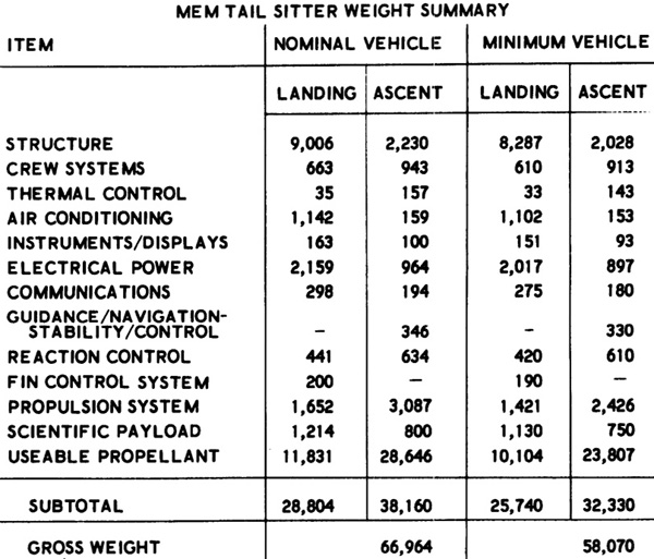
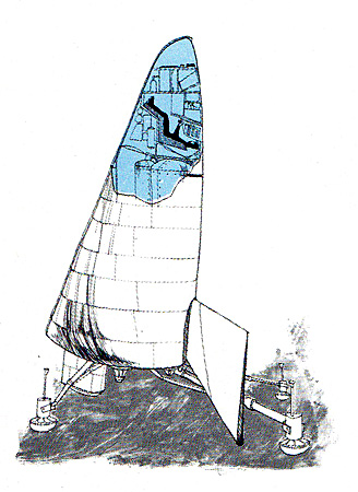
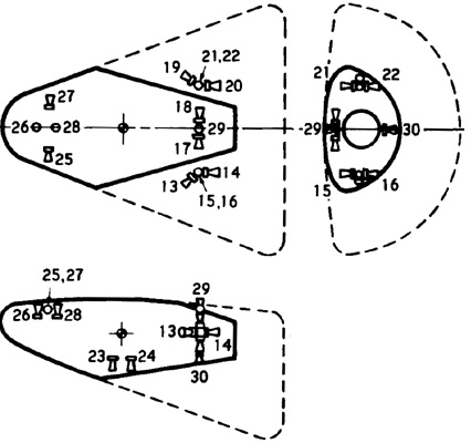
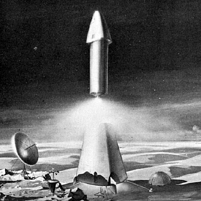
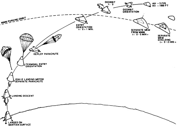
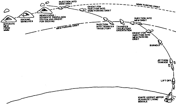
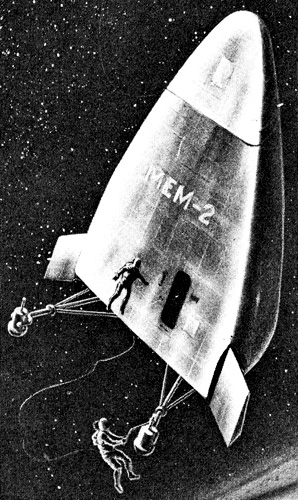
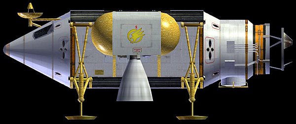
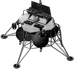
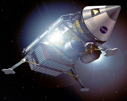
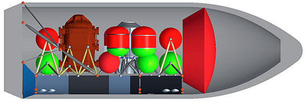
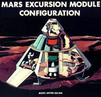
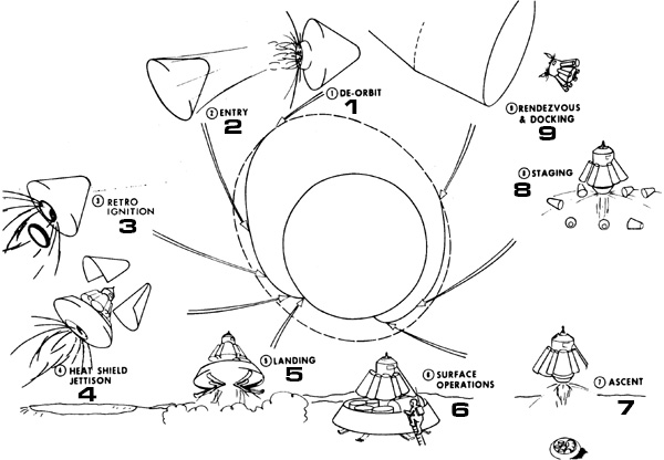
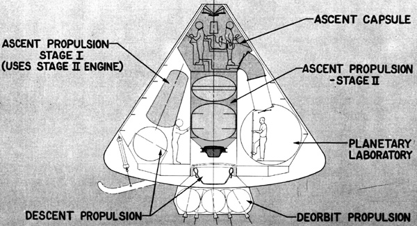
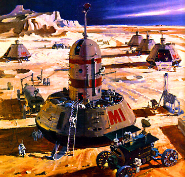
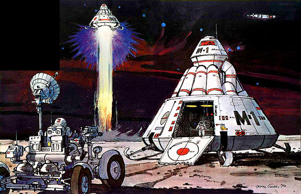
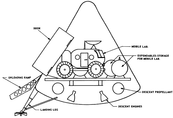
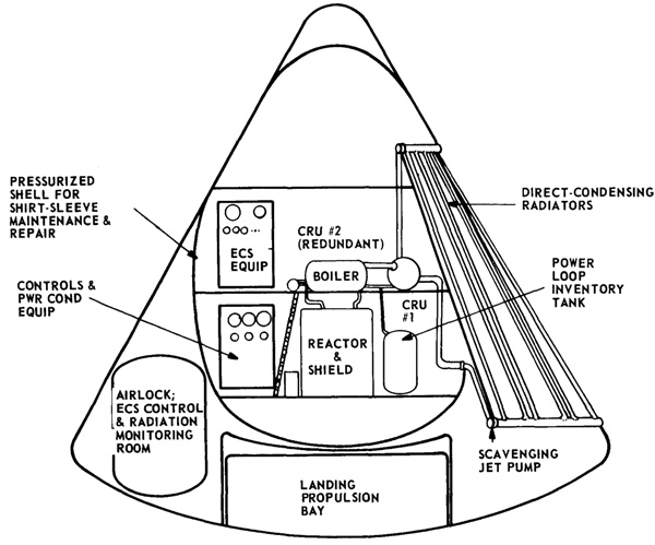
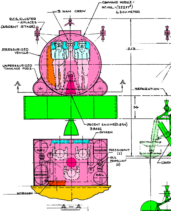
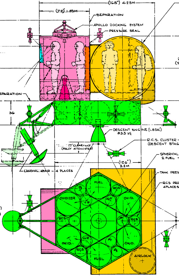
It is used on the 10-Meter Mars Mission Orion. The mission carries two of these, the preferred "tail-sitter" version. The "canted" version has problems, and doesn't fit as well on the Orion. It may also have been used on the Mars Expedition Spacecraft.
Sadly the design assumed a Mars surface atmospheric pressure of 85 millibars. The discovery by the Mariner 4 probe that the actual value was one tenth of this invalidated the design. This is discussed by David S. F. Portree, where he talks about the successor to the Aeronutronics MEM.
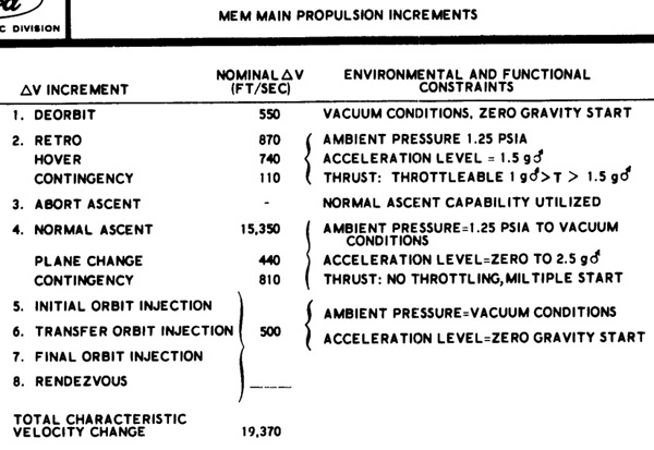
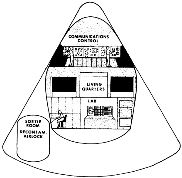
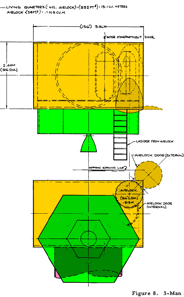
The Aeronutronic MEM was sized for a 40 day stay on the Martian surface with three explorers.
The fuel was a devil's brew of the appallingly corrosive, toxic, and carcinogenic monomethylhydrazine (MMH) mixed with the ever-popular but beyond-insanely-dangerous FLOX. At least it is a re-startable rocket. MMH is hypergolic with any oxidizer, and FLOX is hypergolic with anything.
The reason for this fuel is they needed a specific impulse of at least 375 seconds, but liquid hydrogen fuel just takes up too much blasted room. The designers of the successor to the Aeronutronics MEM had the same problem, so they were forced to use FLOX as well.
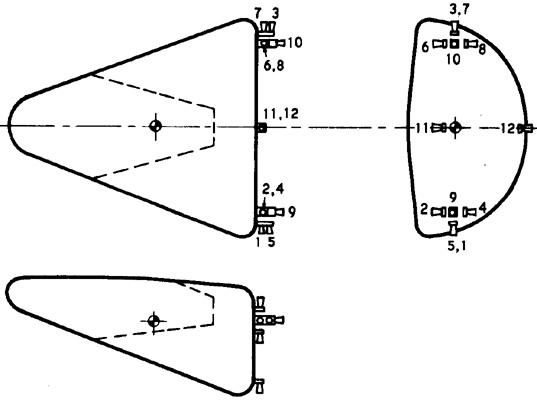
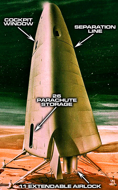
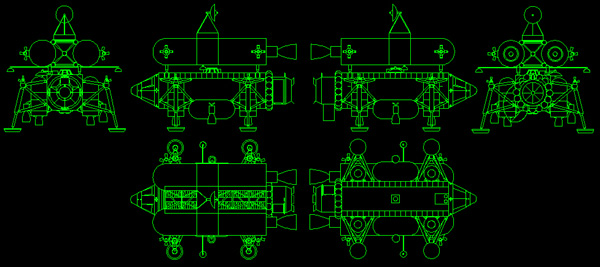
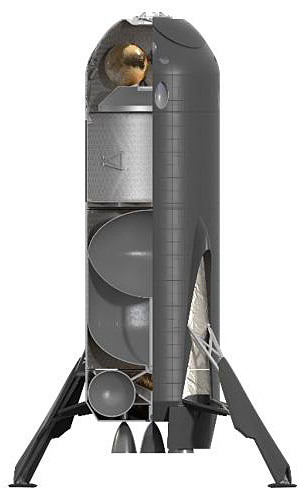
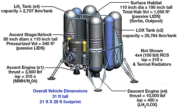
measurements are in pounds
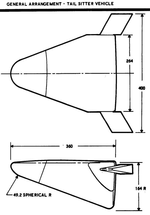
measurements in inches
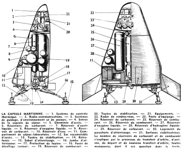
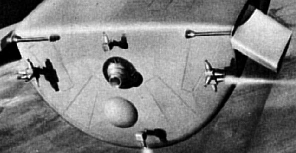
Note distinctive landing feet click for larger image
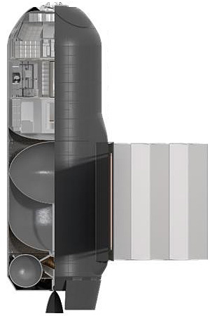
Measurements in inches
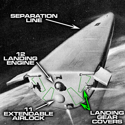
Note extendable airlock at "11"
Note distinctive landing feet
click for larger image
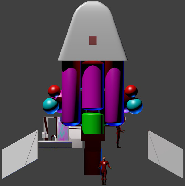
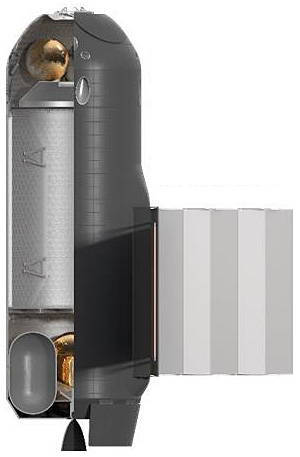
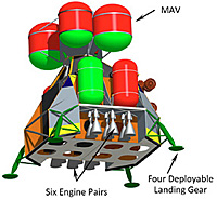
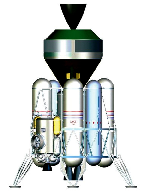
Hot Pink: Oxidizer Tanks
Green: Fuel Tanks
Blue: Liquid Oxygen
Red: Liquid Oxygen artwork by Winchell Chung (me)
Note distinctive landing feet
Note faint outlines of landing gear covers
Placement of descent RCS engines Center-of-gravity mark ⊕ on base (near #11) marks location of landing engine
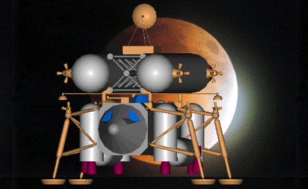
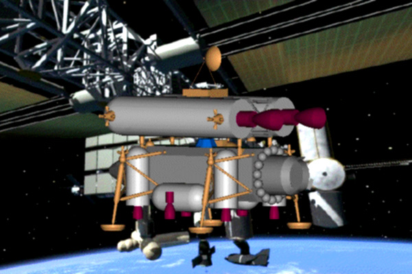
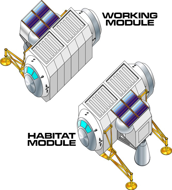
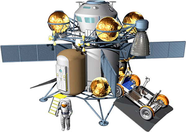
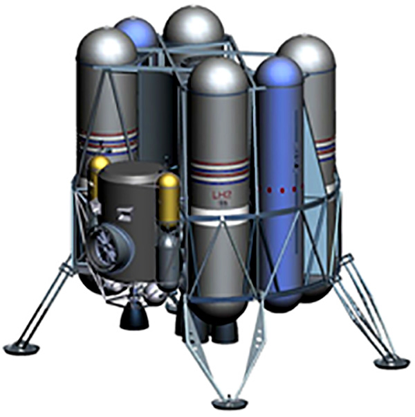
This is from Project Moonlight, a modular lunar mission profile proposed to NASA in 2006 by an Italian team consisting of engineers and scientists from the Italian firms of Alcatel Alenia Space (AAC) of Rome, CIRA of Capua Italy, and the Microgravity Advanced Research and Support (MARS) Center in Naples. The AAC team was lead by Luciano Miccichè, the CIRA team was lead by Gennaro Russo, and the MARS team was lead by Dr. Giuseppe De Chiara.
Project Moonlight proposes a modular lunar exploration architecture that uses many smaller launch vehicles and does not
require a heavy lift launcher such as the NASA VSE Ares V CaLV. The proposal relies on on-orbit cryogenic propellant transfer
and component dockings in both LEO and Lunar Orbit.
While the Moonlight architecture requires more initial launches of smaller components, it aims to provide a reusable lunar
transportation infrastructure consisting of Earth-to-Moon Tugs, reusable landers, and Crew vehicles. This should significantly
reduce the cost of recurring lunar operations, instead of launching an entire infrastructure for each lunar mission as NASA's VSE
intends.
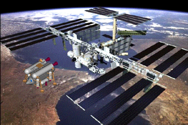
The lunar infrastructure eventually consists of a small space station in lunar orbit, called the Lunar Orbital Operations Platform
(LOOP) logistical station. The lunar station is largely built using existing ISS modules, such as the MPLM for a habitat, a Z1
element with gyros, a docking port node, and an ISS-style truss.
The lunar station would hold multiple docked reusable landers, fuel transported from unmanned Lunar Tanker modules, and
provide a staging area for the crew vehicle.
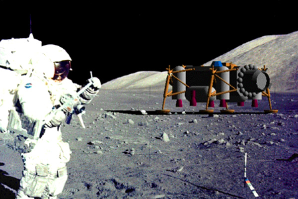
The final phase of the proposal would use the lunar transportation architecture and the reusable modular design of the lunar
lander to land crew habitation modules and other cargo and facilities, forming a permanent or semi-permanent moon base.
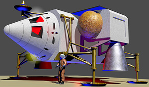
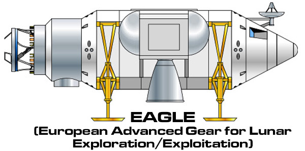
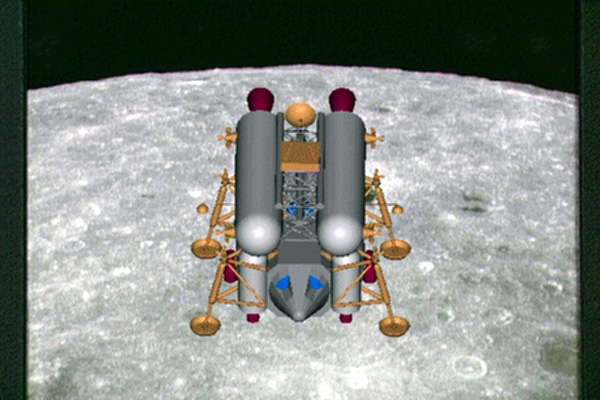
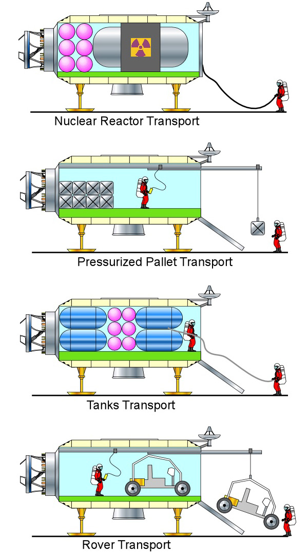
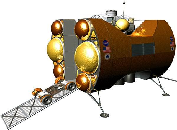
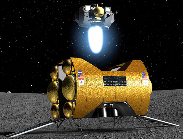
The two designs that are landing spacecraft are the EAGLE (European Advanced Gear for Lunar Exploration) and the Lunar Outpost.
There is a variant design, the EAGLE C which is an uncrewed cargo version of the EAGLE. The EAGLE C is basically an EAGLE with the control compartment replaced with a large cargo port and loading ramp.
Yes, the EAGLE does bear a slight resemblance to the fictional Space 1999 Eagle Transporter. But so does NASA's LUNOX lander proposal. Not to mention the Scorpion. Form follows function, and all are belly landers. So given the same task, it is not surprising that all of the designs resemble each other.
artwork by Marco Gavazzeni, created as an add-on for the Orbiter spacecraft simulator
Since the design was relatively simple, I couldn't resist trying to model it in Blender 3D. It wasn't too hard, though there were a few difficult spots. Mine is not as nice as Marco Gavazzeni, but he has more talent and probably spent more time on it than I did.
click for larger image
click for larger image
click for larger image
click for larger image
click for larger image
click for larger image
click for larger image
click for larger image
Lunar Transportation System
The EAGLE was originally created by Dr. Giuseppe De Chiara for his graduate thesis in 1996. Called the LTS (Lunar Transportation System) project, it had a crewed lander (4 crew) ferried to and from Lunar orbit by an unmanned orbiter. The crew was retrieved in LEO by the STS.
Dr. Chiara's LTS was re-used in the Italian Industrial "Moonlight Scenario" in 2006, as a response to NASA's Constellation program. Dr. Chiara was professionally involved in the development.
click for larger image
Transitional Versions
These diagrams show some transitional steps as Dr. Chiara evolved the LTS into the Eagle.
Common Pressurized Structure click for larger image
click for larger image
click for larger image
click for larger image
click for larger image
click for larger image
click for larger image
click for larger image
click for larger image
click for larger image
click for larger image
click for larger image
click for larger image
click for larger image
click for larger image
click for larger image
click for larger image
click for larger image
click for larger image
click for larger image
click for larger image
click for larger image
click for larger image
EAGLE C
The uncrewed cargo version of the EAGLE. The control cabin is replaced by a large cargo hatch and loading ramp.
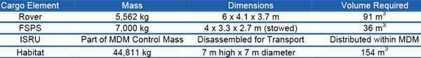
This study looked at the problem of building a
lunar lander to support a small lunar surface base
using one lander that could either land 25 mt (28 t),
one way, or take a 6-mt (7-t) crew capsule up and
down. The initial idea was to build a reusable
lander, suitable for minimizing the transportation
cost to a permanent base, and use it from the first
crewed mission on, taking some penalty and perhaps
expending expensive vehicles early in the program
to avoid building multiple types of landers while
focusing the effort on a space-maintainable, singlestage,
reusable vehicle. A four-engine design for a
multi-purpose vehicle, with total thrust in the range
155,688 to 177,929 N – 53,379
to 57,827 N per engine – and a
throttling ratio in the 13:1 to 20:1 range was proposed.
Initial work indicated a regeneratively cooled, pumpfed
engine would be required due to difficulties with
regenerative cooling over wide throttling ranges with
pressure-fed systems. Three cases of interest were
studied. The first scenario assumed the lunar lander
was used only to place a payload on the surface and
was called the “Cargo Down” case. In this case, the
lander did not have propellant to ascend to orbit after
delivering its payload; it, therefore, stayed on the lunar
surface until refueled. The second case also placed a
payload on the surface, but it carried enough propellant
to return its inert mass to orbit, and was called the “Inert
Returned” case. The third scenario described a case in
which the lunar lander carried a crew module down to
the surface and then back to orbit. This case was called
the “Crew Module Round Trip.”
All three scenarios focused on a single-stage, reusable
lander using nitrogen tetroxide/monomethyl hydrazine
(N2 /O4 MMH) propellants. While the N2 /O4 lander is
considerably heavier than an LO2 /LH2 lander in the
previous section, it is much smaller, due to higher
propellant density. However, features in both landers
are essentially the same. The propellant capacity of
either version of the lander was 35 mt (38.6 t) divided
into four tanks of 16 m3 (565 ft3) each. The tank
diameter was 2.5 m (8.2 ft) for all tanks.
Important features included the following:
An airlock/servicing tunnel down the center of
the lander to allow easy access on the surface and
pressurized volume for Line Replaceable Units. Many
engine connections could be made and broken
inside the pressurized volume.
A removable crew module. The lander was flyable
without the crew module.
The lander fit in a 9-m (30-ft) heavy-lift vehicle
shroud with landing gear stowed.
The landing gear had electromechanical
shock absorbers.
Emergency ascent with one or two crew
members was possible without the crew module.
In that case, the crew would ride in suits in the
airlock/servicing tunnel.
The figure shows this lander being serviced
on the lunar surface and illustrates how the
airlock/servicing tunnel allowed pressurized access
to a surface vehicle. An engine is being removed in
the figure.
Mass breakdowns are included below for the multipurpose
versions of all three cases, using both
LO2 /LH2 and N2 /O4 /MMH propellants.
Mass Breakdown – Multi-Purpose Lander Using LO2 / LH2 Propellant
Cargo Down
Crew Module Round Trip
Inert Returned
Delta-v, Ascent (km/s)
0
2.28*
2.28*
Delta-v, Descent (km/s)
2.10
2.10
2.10
kg
kg
kg
Structure
1,681
1,681
1,681
Engines
822
822
822
RCS Dry
411
411
411
Landing Systems
784
784
784
Thermal Protection
2,017
2,017
2,017
Tanks
3,025
3,025
3,025
Data Management System/GN&C
150
150
150
Electrical Power**
478
478
478
Airlock/Tunnel
455
455
455
Inert Mass
9,823
9,823
9,823
Ascent Prop.
0
11,334
7,240
Descent Prop.
22,597
18,137
20,486
Unusable Prop. (3%)
678
884
832
FPR Prop. (4%)
904
1,179
1,109
Usable RCS
858
689
778
Unusable RCS
43
34
39
FPR (20%)
172
138
156
Total Propellant Mass
25,252
32,395
30,640
Deorbit or Gross Mass (less Payload)
35,075
42,218
40,463
Payload, Descent
25,000
6,000
14,000
Payload, Ascent
0
6,000
0
Deorbit or Gross Mass (with Payload)
60,075
48,218
54,463
Mass Breakdown – Multi-Purpose Lander Using N2O4/MMH Propellant
Cargo Down
Crew Module Round Trip
Inert Returned
Delta-v, Ascent (km/s)
0
2.28*
2.28*
Delta-v, Descent (km/s)
2.10
2.10
2.10
kg
kg
kg
Structure
1,955
1,955
1,955
Engines
956
956
956
RCS Dry
478
478
478
Landing Systems
912
912
912
Thermal Protection
1,006
1,006
1,006
Tanks
1,509
1,509
1,509
Data Management System/GN&C
150
150
150
Electrical Power**
478
478
478
Airlock/Tunnel
455
455
455
Total Inert Mass
7,899
7,899
7,899
Descent
32,861
30,665
31,927
Ascent
0
15,702
9,406
Unusable (3%)
986
1,391
1,240
FPR Prop. (4%)
1,314
1,855
1,653
Usable RCS
990
923
961
Unusable RCS
50
46
48
FPR (20%)
198
185
192
Total Propellant Mass
36,399
50,767
45,427
Deorbit or Gross Mass (less Payload)
44,298
58,666
53,326
Payload, Descent
25,000
6,000
14,000
Payload, Ascent
0
6,000*
0 (Inert Mass returned to LLO)
Total Mass at Deorbit
69,298
64,666
67,326
* Delta-v = 1.85 + 0.43 km/s for a 15-deg plane change in a 93 km circular orbit.
** Electrical power provided for 3 days only, (2 kW). 100% redundant fuel cells/tank sets.
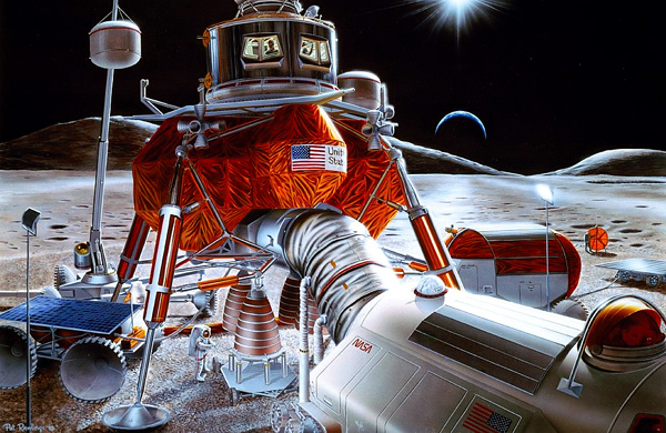
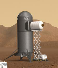
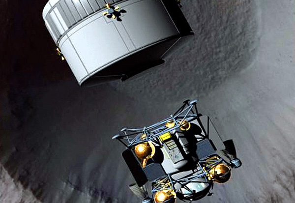
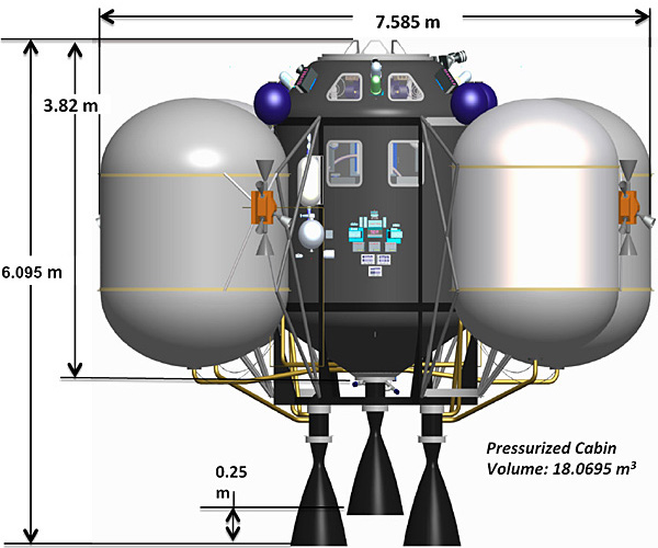
This is a concept designed to support future Lunar and Mars campaigns aimed at establishing self-sustaining human presence beyond Terra orbit. Amazingly this is a mere chemically-powered rocket which is both single-staged and reusable. It also has features allowing full coverage aborts during liftoff and landing from either Luna or Mars, which will bring a smile to everybody's face.
Re-usability is a game-changing feature, which most rocket companies grudgingly admit after SpaceX has rubbed their nose in it, multiple times. With non-resuable Mars landers, every outgoing Mars spacecraft will have to lug along a fresh lander. Which will savagely cut into the spacecraft's payload, making it difficult to grow the Mars base. But with Hercules, you just have to transport one or two of the landers. The rest of the spacecraft visits can have payloads that are 100% base infrastructure.
The other sine qua non of the industrialization of space is in-situ resource utilization. In this case, it mainly means using the magic of the Sabatier reaction to convert the Martian atmosphere into rocket fuel. This will give the The Tyranny of the Rocket Equation a brutal kick in the gonads with steel-shod boots, the fondest wish of all rocket designers. So the Hercules will use methane-oxygen rockets, even though it only has 3,700 m/s exhaust velocity, instead of LH2/LOX's 4,400 m/s. But rocket designers don't care. They will gladly pay the 700 m/s performance hit in exchange for seeing the Tyranny writhing in agony moaning "OW! My Balls!" the vastly increased payload capacity.
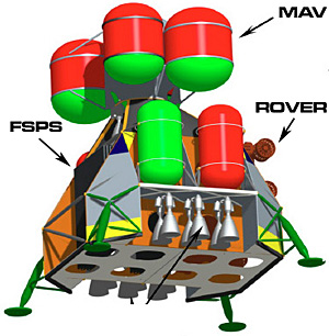
The Hercules Transportation System will be a family of vehicle configurations, built in the same framework (the technical term is "outer moldline" or OML).
HMTV: Hercules Mars Transfer Vehicle [cannot land]
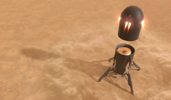
HCRV: Hercules Crew Rescue Vehicle [section that rockets crew to safety in case of abort]
click for larger image
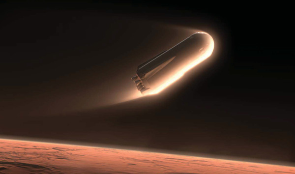
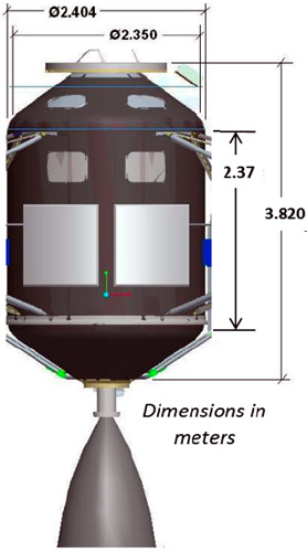
The outer moldline was designed to allow aerodynamic entry into the Martian atmosphere.
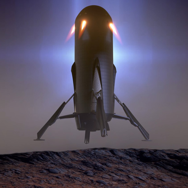
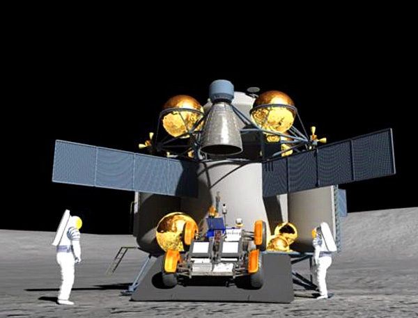
In addition to the main engines at the base (called the Ascent/Descent System or ADS), there are secondary engines at the top attached to the crew compartment (called Abort/Terminal Landing System or ATLS). These are canted 30° outboard from vertical (cosine thrust loss reduces thrust to 87%). The secondaries are used for aborts and for terminal landing. Design-wise you want the abort engines attached to the crew module so it can propel the module away from the rest of the vehicle. And you want the landing engines angled away from the surface to avoid landing in a self-made crater and/or sand-blasting equipment already on the ground(the report calls it avoiding "Surface/Plume Interaction").
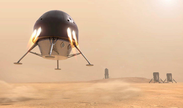
HSRV landing on Mars using the nose section mounted ATLS engines
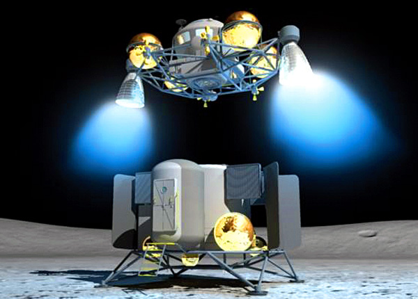
HSRV payload operations illustrating “expendable” scenario where payload bay is separated using nose section
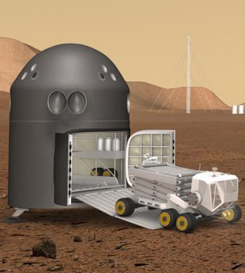
HSRV payload operations reusable scenario where mobility equipment is available for cargo offload
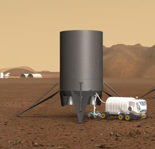
HSRV ascent/descent section repurposed on Mars as a propellant storage facility in support of the in-situ propellant production infrastructure
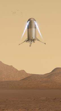
HSRV landing on Mars uses the ATLS for precise payload positioning
HCRV performing hopping manuever on Mars surface
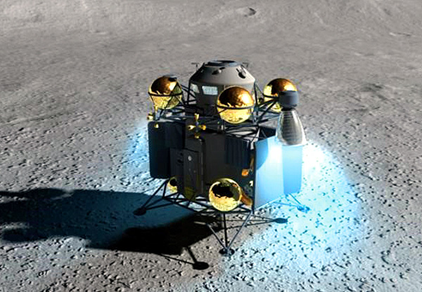
HSRV Lander (Lunar Crew Configuration)
Summary of the HSRV configuration used for lunar crewed flights click for larger image
Lunar Crew Configuration
Subsystem
Descent Mass (kg)
Ascent Mass (kg)
Predicted Mass
14,272
14,272
Structures
5,088
5,088
Thermal Protection
0
0
Landing Legs & Actuation
1,036
1,036
Ascent Propellant Tank
1,936
1,936
Descent Propellant Tanks
318
318
ADS Propellant Feed
418
418
ADS Engines
277
277
ATLS Propellant Tanks
725
725
ATLS Propellant Feed
543
543
ATLS Engines
511
511
RCS Thrusters
114
114
Power & Avionics
850
850
Growth/Margin
2,445
2,445
Propellant Mass
125,838
42,350
Ascent Tank
105,699
22,211
Descent Tanks
10,501
10,501
ATLS Tanks
9,638
9,638
Payload Mass
5,500
5,750
Cargo (Crew Habitat)
5,000
5,000
Crew & Suits
500
500
Samples
0
250
TOTALS
145,610
62,372
The HSRV can deliver up to 20 metric tons of cargo or a crew of 4 to the lunar surface from the Deep Space Gateway(in Near Rectilinear Halo Orbit around Luna), assuming the DSG supplies the cargo/crew and tops off the propellant tanks.
The Lunar HSRV does not have a thermal protection heat shield. That is only used for aerobraking, and there ain't no air around the Moon.
Design Features
Primary Structure: composite; sections designed to separate
Thermal Protection: not required
Propellant Architecture: liquid oxygen and liquid methane (O2/CH4) common across complete system; interconnected propulsion systems
Nose Section
Abort/Terminal landing System (ATLS)
CH4 Tanks: 2 x 2 m diameter at 500 psia
O2 Tanks: 2 x 2 m diameter at S00 psia
Engines: 8 pressure-fed engines installed with 30° cant angle delivering ~60 kN each at min effective Isp 300 sec.
RCS Thrusters: 12 pressure-fed thrusters
Power Generation: 2 internal combustion engines burning O2/CH4 delivering 3 kWe at idle, 40 kWe at max throttle
Habitat Adapter: supports 5.5 t crew hopper habitat
Crew Support: standard docking system; pressurized tunnel to habitat
Payload Section
Crew hopper habitat supporting 4 crew for 3 days
Available Volume: 109 m3
Door Clearance: 4.5 m wide x 3.8 m tall
Ascent/Descent Section
Ascent Tank: common-bulkhead storing O2/CH4 at 30 psia
Descent lanks: dedicated for terminal descent propellant
CH4 tanks: 2 x 2 m diameter at 30 psia
O2 Tanks: 2 x 7 m diameter at 30 psia
Ascent/Descent Engines: 1 pump-fed engine installed at vehicle base delivering ~245 kN at min effective Isp of 360 sec
Body Flap & Actuation: primary control for atmospheric flight
Landing legs: deployable/retractable
Summary of HSRV nose section with crew habitat supporting lunar abort scenarios and crew rescue click for larger image
HSRV – Lunar Concept of Operations click for larger image
Concept of operations for the HSRV at the Moon click for larger image
HPDV Uncrewed Interplanetary Cargo Delivery
The HPDV can deliver 40 to 60 metric tons of cargo to Low Mars Orbit using a Hohmann transfer and aerobraking at Mars. The spacecraft departs from the DSG, having been loaded with cargo and propellant tanks topped off.
The first cargo will be a small space station called an "orbital node." This will be be a place to accumulate subsequent cargo shipments, and as a crew transfer point. The node will be in a 500 km circular LMO at an inclination allowing access to the selected surface base site. The uncrewed node will have multiple docking ports and have autonomous or semi-autonomous robots for in-space assembly and servicing. These robots are used to:
construct and maintain the node
facilitate capture, berth and dock of incoming vehicles
facilitate transfers of payloads between the HPDV (cargo vehicle) and the HSRV (crewed vehicle)
facilitate propellant transfers from the HSRV to various vehicles at the node or to the node itself
The orbital node will also have a large propellant tank used to accumulate methane and oxygen transported from the Mars surface Sabatier factory.
HMTV Interplanetary Crew Transport
The HMTV delivers a crew of 4 to Low Mars Orbit using a 90 to 120 day fast-transfer with aerocapture as Mars. This reduces the crew's exposure to galactic cosmic rays, Hohman transfers take from 180 to 300 days. The spacecraft departs from the DSG, having been loaded with cargo and propellant tanks topped off.
HSRV Lander (Mars Cargo Configuration)
The cargo HSRV can deliver 20 metric tons of cargo from the orbital node to the Mars surface base. At the base it unloads, refuels and travels back to the orbital node. Upon arrival it will have 5 metric tons (5,000 kg) of propellant remaining. This will be added to the orbital node's supply, used to refuel new arrivals.
HSRV Lander (Mars Crew Configuration)
Summary of the HSRV configuration used for Mars crewed flights click for larger image
Mars Crew Configuration
Subsystem
Descent Mass (kg)
Ascent Mass (kg)
Predicted Mass
18,898
18,898
Structures
5,701
5,701
Thermal Protection
2,080
2,080
Landing Legs & Actuation
1,036
1,036
Ascent Propellant Tank
1,936
1,936
Descent Propellant Tanks
318
318
ADS Propellant Feed
474
474
ADS Engines
1,383
1,383
ATLS Propellant Tanks
725
725
ATLS Propellant Feed
543
543
ATLS Engines
511
511
RCS Thrusters
114
114
Power & Avionics
850
850
Growth/Margin
3,216
3,216
Propellant Mass
138,171
12,959
Ascent Tank
121,714
0
Descent Tanks
8,286
6,949
ATLS Tanks
8,171
6,010
Payload Mass
5,500
5,750
Cargo (Crew Habitat)
5,000
5,000
Crew & Suits
500
500
Samples
0
250
TOTALS
162,569
37,607
The crew HSRV can deliver 4 crew from the orbital node to the Mars surface base. At the base it unloads and refuels. At the end of their stay, the 4 crew travels back to the orbital node. Upon arrival it will have 4 metric tons (4,000 kg) of propellant remaining. This will be added to the orbital node's supply, used to refuel new arrivals.
Design Features
Primary Structure: composite; sections designed to separate
Thermal Protection: mechanically-attached ACC6 hot structure with opacifed fibrous inslation
Propellant Architecture: liquid oxygen and liquid methane (O2/CH4) common across complete system; interconnected propulsion systems
Nose Section
Abort/Terminal landing System (ATLS)
CH4 Tanks: 2 x 2 m diameter at 500 psia
O2 Tanks: 2 x 2 m diameter at S00 psia
Engines: 8 pressure-fed engines installed with 30° cant angle delivering ~60 kN each at min effective Isp 300 sec.
RCS Thrusters: 12 pressure-fed thrusters
Power Generation: 2 internal combustion engines burning O2/CH4 delivering 3 kWe at idle, 40 kWe at max throttle
Capsule Adapter: supports 5.5 t separable crew capsule
Crew Support: standard docking system; pressurized tunnel to habitat
Payload Section
Crew hopper habitat supporting 4 crew for 3 days
Available Volume: 109 m3
Door Clearance: 4.5 m wide x 3.8 m tall
Ascent/Descent Section
Ascent Tank: common-bulkhead storing O2/CH4 at 30 psia
Descent lanks: dedicated for terminal descent propellant
CH4 tanks: 2 x 2 m diameter at 30 psia
O2 Tanks: 2 x 7 m diameter at 30 psia
Ascent/Descent Engines: 5 pump-fed engines installed at vehicle base delivering ~245 kN each (1,225 kN total) at min effective Isp of 360 sec
Body Flap & Actuation: primary control for atmospheric flight
Landing legs: deployable/retractable
Separable HSRV nose section with separable crew capsule supporting Mars abort scenarios click for larger image
HSRV – Mars Concept of Operations click for larger image
Concept of operations for the HSRV at Mars click for larger image
Reusable Hercules Taxi Service Surface Ops and Support Functional Model click for larger image
Human Lunar Return Lander
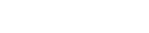
The Human Lunar Return study was
desperate attempt to put astronauts back on Luna at a bargain-basement price. It was one of the last gasps of NASA's Faster-Better-Cheaper design approach.
Yes, I can understand NASA's panicked need for space projects that cost only a few hundred million dollars instead of billons. But if the Apollo Lunar Excursion Module was an antarctic exploration tractor, the Human Lunar Return lander was a unicycle. Blasted thing didn't even have a hull, it was basically a rocket engine with two chairs welded on the top. The contraption is only slightly more sophisticated than the North American Rockwell Moon Hopper.
1996-HUMAN LUNAR RETURN
HLR Option C. This alternative fallback option eventually evolved into HLR's final 1996 baseline after NASA Administrator Dan Goldin criticized the comparatively high cost of the effort at a November 1995 briefing to the Administrator. Goldin wanted "incredible breakthroughs" costing at most a few hundred million dollars rather than billions. The HLR team responded by focusing on bare-minimum lightweight concepts such as Option C's "small lander". Anything that wasn't absolutely necessary (e.g. the LEO cryo fuel depot or lunar orbit station) was to be deleted.
To save weight, HLR would use an unpressurized open-cockpit lunar landing vehicle weighing just 4,565kg with fuel. The vehicle is 3.9 meters tall and 5.6 meters wide. The space-suited crew of two receives oxygen and other life support consumables via umbilicals from the LLV. In the illustration here, arrows indicate foot restraints and ladder. [What a ride that would be!]
The Lunar Orbit Stage (formerly known as Transtage) is protected by a 9.144-meter diameter aeroshell, which is launched in seven segments to save space. The aeroshell is assembled before rendezvous with ISS and then moored to the Space Station. A second Shuttle flight delivers the crew and propellant for the lunar vehicles. The refueling operations are simplified since the LOS and LLV utilize storable hypergolic propellants, which require no new propellant transfer technologies. The 15.6-tonne LOS vehicle only carries enough propellant for lunar orbit insertion and trans-Earth injection; two expendable 20-tonne propulsion modules (derived from the Russian "Breeze" upper stage and launched on two Proton rockets) perform the translunar injection burn. The LOS carries a small unpressurized Lunar Landing Vehicle and a 2.5 meter long Command Module capable of supporting two astronauts for up to 19 days during the Earth-Moon transfer. Date of departure from ISS: August 24, 2001.
NASA Administrator Dan Goldin initiated the “Human
Lunar Return” (HLR) study in September 1995 to
investigate innovative, fast-track approaches for crewed
spaceflight. The HLR team worked through two initial
concepts in an effort to produce the ultimate cut-rate
faster-better-cheaper human lunar mission. The 1996
baseline design was a bare-minimum lightweight
concept in which anything not absolutely necessary
(e.g., the LEO cryo fuel depot or lunar orbit station)
was deleted. It consisted of a Lunar Orbit Stage (LOS),
the Lunar Landing Vehicle (LLV), and the Habitat.
The LOS was protected by a 9.144-m diameter
aeroshell since it would be aerobraking back into LEO
when returning from the Moon. The shell was to be
launched in seven segments to save space, assembled
on orbit, and moored to the International Space Station
(ISS) pending integration with the Lunar Orbit Stage.
A Space Shuttle flight would deliver the crew and
propellant for the lunar vehicles to the ISS, and the
LOS and LLV, together with the crew, would depart
for the Moon. On the return trip, the LOS would again
dock with the ISS after which the crew was to return
to Earth via the Space Shuttle.
The 15.6-mt LOS vehicle carried only enough
propellant for lunar orbit insertion and trans-Earth
injection; two expendable 20-mt propulsion
modules (derived from the Russian “Breeze”
upper stage and launched on two Proton rockets)
performed the Trans-Lunar Injection (TLI) burn.
The LOS carried a small, unpressurized LLV and a
2.5-m long Command Module capable of
supporting two astronauts for up to 19 days during
the Earth-Moon transfer.
The open-cockpit LLV weighed just 4,565.3 kg, including fuel, and was 3.9 m tall by 5.6 m wide. The space-suited
crew of two received oxygen and other life support
consumables via umbilicals from the LLV. After
landing, they were to live in the inflatable Surface
Habitat that had been delivered prior to their arrival.
Following departure from the lunar surface, the crew
reboarded the LOS and the LLV was jettisoned prior to
trans-Earth injection.
Baseline for the Expendable Crewed Lander
Vehicle
Open cockpit sized for two crew in Extravehicular Mobility Unit (EMU)/Portable Life Support
System (PLSS)
LOX servicing at pad pre-launch; vent and servicing interfaces integrated into upgraded
non-toxic Orbiter
Structures
Truss frame structure, composites where feasible
Single-stage, four-leg landing gear with load attenuation
Cockpit frame/payload box provides structural interface to PLSS
Propulsion
Single-stage pressure-fed LOX/RP1
14,679 N, 4:1 throttling main engine w/no gimbal
200 N, 6 DOF Reaction Control System (RCS)
Guidance Navigation & Control
Auto-rendezvous and Auto-Land w/Redesignation
Daytime hazard detection (shadow based)
Star Tracker, Deep Space Network, Inertial Navigation System, Laser altimeter, Beacon, LIght Detection And Ranging (LIDAR)
Power
Two low-mass Proton Exchange Membrane (PEM) fuel cells (load sharing/redundant)
Avionics / Communication
Non-Commercial Off-the-Shelf reduced mass
Computer, S-Band, Ultra-high Frequency, video (descent and ascent)
Life Support
New EMU with amine swing bed CO2 removal
EVA resources via umbilical during ascent/descent
Thermal
Multi-Layer Insulation, Passive with heaters/radiators
Jet Propulsion Laboratory Phase II Concept: 0609-LLPS-JPL
The Jet Propulsion Laboratory ( JPL) Phase II concept
horizontal configuration facilitated large cargo
deployment and simplified crew egress/ingress. The
sortie lander was reconfigurable and directly extensible
to outpost deployment and logistics resupply missions.
The split habitat and minimum volume ascent stage
improved vehicle performance to enhance payload-tothe-
surface capability. The four engine descent stage
main propulsion system provided engine-out capability
during descent.
Descent Stage
Power
9 kW photovoltaic array (30 m2 total in two Ultraflex solar arrays, 100 kg mass). MobiLander
Stage: regenerative H2 /O2 fuel cell hybridized with large-format Li-ion batteries (5000 cycle lifetime, 27.8 kWh
capacity, 216 kg mass).
Propulsion
RL10A4-2 engine, Isp 451, thrust 99 kN, gimbal (±4°), throttleable (100% to 20%); also densified
propellant, multiple tank configuration, increased in surface area/heat leak, multiple tank drain LH2 systems sensitive
to differential pressures.
Thermal
LOX/LH2 active cryo cooling to support the 95-day LEO stay
MobiLander: Passive cooling and boil-off for the trans-lunar flight and landing. Pre-cooling, passive cooling, and
boil-off for the trans-lunar flight and landing. Sun/Earth shade to minimize cryo cooler power requirement in Low
Earth Orbit (LEO). Thermal radiators for Environmental Control Life Support (ECLS) and fuel cell heat exchangers were
mounted on the MobiLander habitat.
Guidance, Navigation & Control
Radar altimeter provided altitude and horizontal and vertical velocity relative to surface. LN-200S and Mars Exploration
Rover (MER) heritage navigation cams and hazard cams were to be used for surface navigation and hazard avoidance.
Ascent Stage
Power
Li-CFx, 8-hour lifetime, 12 kWh capacity, 25 kg mass
Propulsion
Pump-fed MMH/NTO main engine, increase in Isp ~7.5%, XLR-132 engine Isp 340, thrust 22KN, fixed (no gimbal).
Thermal
Outer surface covered with foam insulation plus 60-layer MLI (consider foam core shield, provided both thermal
insulation and micrometeoroid protection). Radiators were mounted to MobiLander stage. Evaporative cooling during
ascent.
Guidance, Navigation & Control
Storable (MMH/NTO) pressure-fed system, 16 at 490 N thrusters, Isp 321 sec. Star trackers and gyros for
stellar inertial attitude determination. Accelerometers for position determination during descent and ascent. Scanning
LIght Detection And Ranging (LIDAR) for rendezvous (couple of kilometers to tens of meters). Wide-angle camera used
during terminal rendezvous (tens of meters).
When Jet Propulsion Laboratory (JPL) was asked, along with the other NASA centers, to contribute innovative
concepts for the next human lunar landing, we asked ourselves what could we bring to the table that others
might not. After much internal discussion, we latched onto one of the principal goals of the study: to maximize
reuse of hardware sent to the Moon, and particularly reuse of hardware from short-duration early crew visits
(i.e., “sorties”) in buildup of a permanent outpost. This goal implied a need to provide mobility for landed
assets, and mobility on extraterrestrial surfaces is something we know a lot about – both from our Mars rover
experience and from work we’ve been leading to develop the ATHLETE system described below. So, we set
out to design a highly mobile habitat for the first lunar crews that could enhance exploration during the 4- to
7-day sortie mission and then could be moved, under telerobotic control from Earth, to become part of the
lunar outpost.
We did most of the work in our “Team X” concurrent engineering environment, which facilitates rapid
development of conceptual designs for a wide variety of space missions. At first we treated the crew members
and their gear as just one more payload, to be delivered to the appropriate place in the Solar System, but we
quickly realized that we had to deal with two major differences between crewed missions and the robotic solar
system exploration missions that we are used to designing: (1) that crew safety is a critical overarching factor
affecting every aspect of the design; and (2) that the crew is an integral part of the mission operations system.
Fortunately, the sponsors of the study had established an environment to facilitate inter-center cooperation. We
were able to make a highly experienced astronaut, Andy Thomas, a part of our team, and to call upon various
other crew system experts to assure that our design was appropriate for a crewed mission.
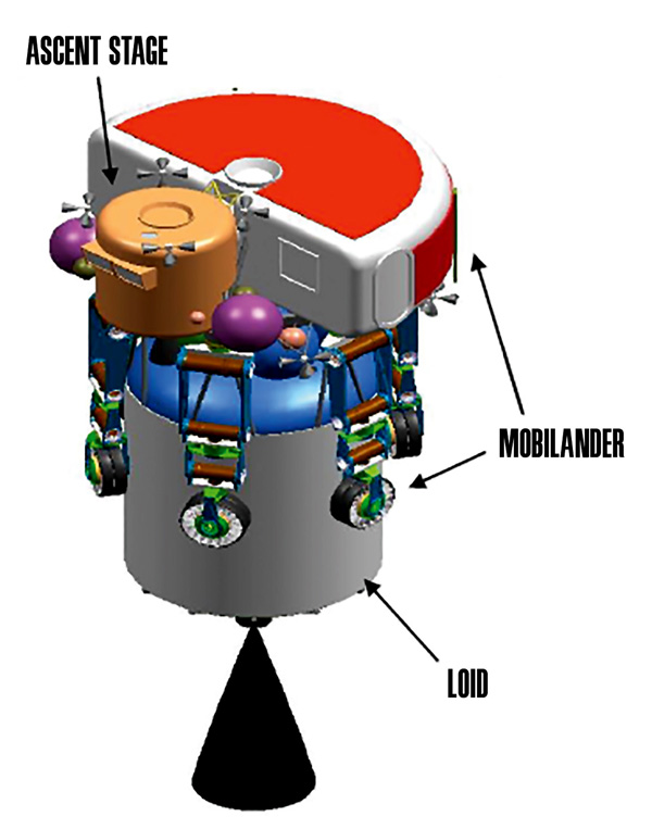
The product of our effort was the MobiLander concept illustrated here. This concept comprises three elements:
(1) the Lunar Orbit Insertion and Descent (LOID) stage, which provides all of the propulsive capability for lunar
orbit insertion (LOI) and part of the capability for deorbit and descent before being discarded to impact the
Moon many kilometers from the landing site; (2) the MobiLander element, which provides the remainder of the
descent and landing propulsion, an integrated landing and mobility system, and a spacious habitat; and (3) a
small ascent stage with minimum functionality needed to transport the crew from the lunar surface to the Orion
Earth return vehicle waiting in lunar orbit. Once on the surface, the MobiLander has the capability to transport
the crew in pressurized comfort tens of kilometers per day and, after a sortie crew returns home, to traverse
hundreds or thousands of kilometers to perform scouting and be available as a backup at the next sortie
landing site and/or to become part of a long-term outpost facility.
As launched from Earth, the MobiLander stack includes
the LOID stage and the Ascent Stage as well as the
MobiLander itself.
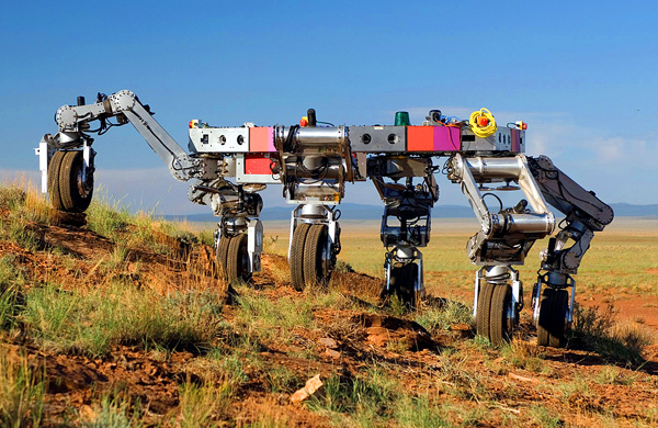
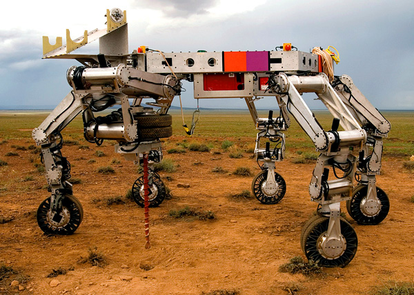
ATHLETE is the All-Terrain, Hex-Limbed, Extra-Terrestrial Explorer,
which is a mobility, manipulation, and landing system being funded
by the NASA Exploration Technology Development Program for
lunar applications. It has six wheels on the ends of six limbs, each
with six degrees-of-freedom so the limbs can place the wheels
in any position and orientation within a substantial work volume.
The wheels provide power-efficient rolling mobility on moderate
terrain, while the limbs provide active suspension to reduce the
“jouncing” effects of moderate-speed driving in low gravity, and
also enable walking mobility on extreme terrain. Each wheel has
a quick-disconnect tool adapter that allows tools to be extracted
from a “tool belt,” with a power take-off from the wheel supplying
power to the tool. The prototype vehicles that have been built
are half-scale at 2.75 m across, a mass of about 850 kg, and a top speed of about 10 km/h. The
legs on a full-scale lunar system would have a combined mass
of about 5% of the total vehicle mass of almost 20 mt.
Landing is accomplished by using an air bag deployed under the
launch adapter ring (that connects the MobiLander to the LOID
from launch to the time the LOID stage is dropped) to dissipate
the landing energy by venting gas through an orifice, while the
ATHLETE limbs are used as outriggers to prevent tip-over.
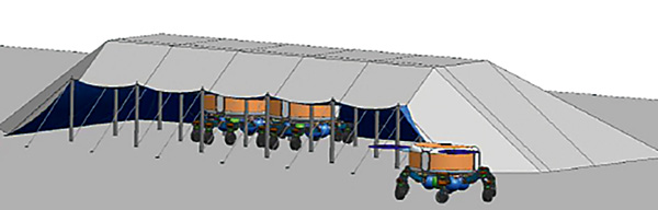
MobiLanders link together to form the outpost core after erecting a dirt-covered tent for protection from solar radiation and cosmic rays.
Athlete climbing a hill
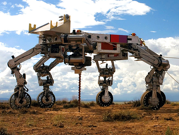
Athlete using its tool adapter
Athlete using its tool adapter to drill into the ground
Having both mobility and manipulation in the
MobiLander provides many benefits. The vehicle can
squat while all six limbs perform manipulation for
self-maintenance, science instrument placement, or
sample gathering. A small glove box at the base of
the vehicle will allow astronauts to handle and inspect
samples without going through all the rigors of getting
into their space suits. A small airlock for samples will
allow them to bring samples of special interest into the
habitat for study or archiving. The limbs will be able
to perform construction operations such as building a
tent that can be covered with dirt for protection from
the radiation of occasional solar flares, or just from the
long-term effects of galactic cosmic rays. A trenching
tool will allow utility cables to be protected from micrometeorites. A larger “dozer blade” will allow substantial
amounts of loose surface material to be collected for processing as a resource — e.g., to extract oxygen. Auger
bits allow sampling of deeper materials to search for resources, as part of a science investigation, or to emplace
anchors as needed to put up the radiation-protection tent or to support rappelling down steep slopes (such as
into craters). Lunar outpost buildup requires mobility for large elements, since these cannot be landed in the
middle of the outpost. Our study designed a long-range mobility system that can be incorporated into the crew
habitats starting in the sortie phase at small incremental mass cost. This concept provides several advantages:
maximum reuse of sortie hardware in outpost buildup, extensive robotic prospecting and detailed scouting of
future landing sites, reduced number of cargo missions to achieve full outpost capability, long-range pressurized
roving available in every mission with options for non-extravehicular activity (e.g., glove box) science, flexible
manipulation capability, positioning of large cargo elements after landing, and safety and robustness for all lunar
surface operations. Our study showed that these advantages of long-range mobility can be achieved consistent
with program resources and constraints for mass, cost, risk, and technology development schedules.
The Descent Assisted Split Habitat (DASH) lander
concept included a Retro Module that staged prior
to landing, thus facilitating cargo deployment and crew
egress/ingress. This sortie lander was reconfigurable
and directly extensible to outpost missions. A split
habitat, minimum-volume ascent stage improved
vehicle performance to enhance payload-to-the-surface
capability. Use of inflatables for expanded surface
habitat volume provided excellent pilot visibility
and the ability to tailor the pressurized volume for
mission needs.
Descent Stage
Power
Power (batteries) to support pressurized logistics in rigid core derived from the surface habitat.
Propulsion
Single non-throttling 110,049.2 N RL10B-2 engine (LOX/LH2); RM performs Lunar Orbit Insertion (LOI)
and ~90% of the lunar descent.
Thermal
Reduced capability from sortie lander for the following: heat exchanger, fluid loop heat rejection, cold plates, 10 mil
Ag-Teflon single-sided radiators, and Multi-Layer Insulation (MLI) blankets.
Structures
Vertical cylindrical configuration, 1.75 m in diameter, volume approximately 6.0 m3.
Good structural support from existing truss underneath. More efficient design for airlock in a smaller
volume (6 to 10 m3 range). Not as efficient if scaled up to around 20 m3.
Dust guard room in rigid central habitat may be necessary to support suit donning/doffing.
Ascent Stage
Power
Four Li-ion batteries (125 Whr/kg specific power and 200 Whr/L specific density). 3-hr lifetime,
4.5 kW capacity, 55 kg/battery
Propulsion
Two 26,689.8 N Orbiter Main Engine (OME) derived MMH/NTO pressure-fed engines;
316 Isp and 1,911 m/s delta-v capability
Telecommunications
Two S-Band transponders, one S Band dual-beam antenna, one K-Band radar signal processor, two K-Band
transponders. Phased array Ka/Ku-Band antenna type, two UHF Transceivers, two UHF antennas
Thermal
MLI-50 flexible blanket with 5.7-cm thickness
Structures
Aluminum-Lithium (Al 2195) I Beams and grid-stiffened panels. 65.5 kPa internal pressure
Guidance Navigation & Control
Two star trackers, two LIght Detection And Ranging (LIDAR)/LADAR, two cameras, two radar altimeter, four GPS/INS,
two radar antennae, 445.2 N NTO/MMH Reaction Control System (RCS) engines (16 total)
The DASH lander mated to the Orion Crew Exploration Vehicle in
Low Lunar Orbit.
NASA’s Descent Assisted Split Habitat
lander may provide the key for future,
routine access to the Moon’s surface
Houston, this is lander Hercules.
All systems are ready for
descent braking initiation.”
– “Roger that Hercules, you
are go for powered descent.
The Retro Module performs the descent braking burn from an altitude of
15 km to just over 5.3 km.
The
With that exchange between the commander of the
lunar lander Hercules and NASA’s Mission Control,
the Lunar Expedition I crew began their historic
descent to the lunar surface. On the afternoon
of September 30, 2020, the four crew members
climbed out of their Orion Crew Exploration Vehicle
(CEV), entered the next-generation lunar lander, and
safely landed at the Moon’s Aristarchus Plateau.
The lander will become NASA’s workhorse for a
series of missions designed to comprehensively
explore the Moon and establish an outpost allowing
for continuous human presence on the lunar
surface. The Descent Assisted Split Habitat (DASH)
lander was conceived by a team of engineers at
the Langley Research Center located in Hampton,
Virginia, during the summer of 2006. DASH is a
versatile lander that uses a disposable braking
stage, called a Retro Module, during most of the
lunar descent along with a small crew module
for the short trip to and from the surface. Human
missions such as the proposed Apollo direct flight
approaches included the use of a lunar braking
module and the Russian LK lander included the use
of a “crasher stage.” These innovative approaches
for landing humans on the Moon combined with the
desire to get the crew and cargo extremely close to
the lunar surface inspired the Langley engineers to conceive of the DASH lander. Fourteen years later, and more
than 50 years after Neil Armstrong first set foot on the Moon, NASA’s vision to return to the Moon has become
a reality. Now 1 week later, with the crew safely aboard the CEV and about to begin their 3-day journey back to
Earth, the Hercules lander is ready to perform its final operational maneuver – a short thruster burn to deorbit
the vehicle. In the future, the lander will be modified to be refueled in lunar orbit and await the next outpost crew
arrival. For now, Hercules’ mission is complete. Provided here is a review of the DASH lander design and its role
in NASA’s successful return to the Moon.
The Retro Module separates from the Lander Module and Payload Module
and impacts the surface over 3 km downrange of the landing site.
The DASH lander is composed of three modules: the Lander Module, the Payload Module, and the Retro
Module. Although the Lander Module, which carries the four crew members within the pressurized Transport
Habitat, contains the primary vehicle flight controls and critical subsystems, the first phase of the lunar landing
was dominated by the 9.3 m long Retro Module. The Retro Module is a high-performance in-space
braking stage powered by a LOX/LH2 propulsion system. The non-throttling engine is capable of producing
110 kN of thrust. Having already successfully completed the lunar orbit insertion maneuver with the
CEV attached, the Retro Module was activated again to perform two critical maneuvers. The first small burn
kicked the DASH lander from its 100 km altitude parking orbit into an elliptical orbit with a perilune
altitude of 15 km. With the astronauts still weightless, it was time for the Retro Module to perform the
second maneuver. The Retro Module operated flawlessly during its 5.4-minute braking burn that canceled the
spacecraft’s orbital velocity and effectively brought the lander to a relative standstill 5.3 km above
Aristarchus Plateau. With no direct viewing of the surface possible during this mission phase, Commander John
Stevenson and Pilot Kathy Reynolds used heads-up displays and the lander instruments to guide themselves
and Mission Specialists Scott Jones and Mike Ross to the Retro Module jettison altitude.
At this point, the Retro Module’s job was complete. Moments after main engine cutoff, the expended stage
separated and safely followed a predictable ballistic trajectory to its impact point 3.2 km downrange of the
landing site. This was a satisfying moment for the NASA engineers that proposed this alternative approach to
traditional two-stage vertical landers. Dan Mazanek, the DASH concept team leader, recalls the initial resistance
to the use of braking stages. “We use staging all the time in launch systems. If we didn’t, we would still be stuck
on Earth. I remember using the term ‘separation anxiety’ to describe some folks’ early concern with braking
stages. It’s terrific to see how beautifully the DASH system performed. The lander’s benefits far outweigh the
relatively minor risks associated with staging.” The biggest benefit is proximity to the surface. The large, empty
propellant tanks on an equivalent two-stage lander force the crew or any large cargo to tower over three stories
(~10 m) above the lunar surface. The tank height is primarily driven by the launch vehicle fairing diameter.
Cranes, elevators, and other devices can overcome this, but add considerable complexity, cost, and risk to
surface operations. The simplest approach is to be close to the surface and use ramps to deploy cargo and
short ladders or ramps for crew access. The crew and cargo height from the surface for DASH is approximately
1.2 m and is limited only by the need to avoid rocks on the surface. Additionally, the DASH lander
provides mass reductions compared to similar two-stage lander designs. Kandyce Goodliff, one of the DASH
team co-leads, adds, “We found that the DASH lander was nearly a metric ton lighter than the two-stage lander.
An Apollo-like approach with a single habitat was 3.5 metric tons more massive than DASH – not to mention
the surface access problems. The DASH lander has definite performance benefits.”
Since the Moon has no atmosphere, the flight path of the vehicle is much easier to predict than for spacecraft
going through the atmosphere, as with those returning to Earth or future missions to Mars. “This is aided by
our much better understanding of the Moon’s gravitational field than during the Apollo missions. The descent
trajectory was designed to assure that the Retro Module impacts harmlessly downrange of the landing site,”
explains Mazanek. Although not critical on this 7-day sortie mission, this becomes an important consideration
for outpost missions. Any design, even single-stage landers, must guarantee that surface assets are protected
during nominal lander operations and abort situations. The DASH trajectory assures that if the Retro Module is
jettisoned during a descent abort contingency, it will land no closer than 3 km from the outpost.
“For much of the descent the impact point is tens to hundreds of kilometers downrange. Also, for outpost
missions the surface assets will be placed out of plane from the lander descent path, and the lander will perform
a ‘dog-leg’ type maneuver that curves toward the outpost location late in flight,” adds Dave Cornelius, the other
DASH team co-lead. On future missions the crew plans to visit the Retro Module’s impact site to gain valuable
engineering data on the vehicle’s performance and survivability of components. It’s even conceivable that
someday the discarded stages could be used as a recyclable resource.
The Lander Module and Payload Module just prior to lunar touchdown.
After jettison of the Retro Module, two highly reliable hypergolic engines ignited in unison and the Lander
Module and attached Payload Module began the 90-degree pitch over maneuver to orient the lander for
touchdown. The Lander Module engines perform the final portion of descent and the precision landing
maneuvers, as well as provide abort to orbit at any point during the descent. Commander Stevenson
commented that it was impressive to see the large Retro Module as it drifted away from the lander.
The 30 mt Retro Module represents two thirds of the entire DASH lander wet mass of just under
45 mt. “We had a terrific view of the Retro Module out the main windows as we pitched over. We were
able to see it all the way to the surface,” said Stevenson.
The 26.7 kN Lander Module engines,
derived from the Space Shuttle Orbital Maneuvering
Engine (OME), provided a smooth, balanced thrusting
for the last 2 minutes of the descent. The gem shape
of the Transport Habitat allows for the efficient use
of the limited volume, maximizing usable space at
arm/chest height while simultaneously allowing for
downward-facing windows for commander and
pilot visibility during the landing phase. The mission
specialists are seated at the rear of the Transport
Habitat. The desire to provide efficient mass staging
by splitting the habitable volume and allowing the
Surface Habitat to remain on the surface required that
multiple engines be used on the lander. The approach
provided another huge benefit for the DASH design by
greatly increasing the height of the engines above the surface to nearly 3.7 m. This effectively reduces
surface plume debris and also permits a lower vertical touchdown velocity, which reduces landing gear mass.
Unlike Apollo, which had to cut off the descent engine about a meter above the surface, DASH is able fire its
engines until the landing pads actually touch down. Engine height also turned out to be critical to reduce dust
interference with the hazard avoidance and landing system, which uses a laser imaging system to detect rocks
and boulders on the lunar surface.
As Reynolds carefully piloted the Hercules lander to the surface, she noted, “We had a great view of the lunar
surface and the dust wasn’t bad at all. The small, agile DASH lander was a pleasure to fly,” said Reynolds. This
agility will prove to be important on future missions where navigation over the mountainous polar terrain will be
much more difficult. The compact lander also proved beneficial during its development on Earth. The complexity
and cost of rigs to support the construction and testing of the DASH lander were significantly reduced, since
the Retro Module was not connected during the crucial operations near the surface. The ability to build the
modules separately and then integrate them with relative ease also helped in the lander development process.
Several engine configurations were considered for DASH; however, the two-engine configuration was chosen
for multiple reasons. It was the simplest approach offering the best packaging and least mass solution, and
eliminating coupled radiative heating and plume interaction issues encountered in four engine in-line and sideby-side designs. In addition, the demonstrated high reliability and extensive heritage of the N2O4/MMH engine
systems have proven that the additional risk incurred by flying a two-engine design over a single-engine design
is insignificant, since feed system redundancy was incorporated as was done for the Apollo Lunar Module
descent stage. The OME was fired more than 2,000 times without failure during Space Shuttle flights, and was
inspected for damage after each flight, so its characteristics were well understood. The only engine modification
required for DASH was the ability to throttle the engine back to around half thrust during touchdown and ascent.
The pintle throttle demonstrated on the Apollo descent stage provided confidence that the OME could be
successfully and safely modified.
Astronauts lower the Lander Module’s plume shields, which double as
deployment ramps, then activate the lunar rover.
One of the design challenges for the DASH lander was controlling the exhaust plume from the Lander Module
engines. When the concept team first proposed the dual use of plume shields as ramps for offloading of cargo,
they knew that shield temperature control, pressure loading, vehicle plume heating, and contamination from
hypergolic propellants would need to be addressed.
Careful design and testing resulted in plume shields
that efficiently direct exhaust away from the vehicle.
Stevenson confirmed that exhaust plume effects
on the lander structure were virtually undetectable.
“Houston, we’ve got a clean bird here at Aristarchus,”
was the message relayed by the commander after
the crew inspected the lander during the initial surface
Extravehicular Activity (EVA). Mission Specialists Jones
and Ross were responsible for lowering the two shield
ramps that protect the external cargo bays during the
first EVA. Each bay can hold approximately 5 m3
of unpressurized cargo, including the lunar rover and
various scientific equipment. “The ramp mechanisms
worked just like they did during training,” complimented
Ross after the 8-hour work shift on the surface.
The crew of the Hercules spent a total of 7 days exploring the Aristarchus Plateau region and performed
a record 10 surface EVAs. They provided a comprehensive survey of the area and are returning over
100 kg of rock and regolith samples. The DASH Payload Module, which is left on the surface, provides
a versatile platform that can accommodate both pressurized and unpressurized payloads – specifically lunar
surface habitats, outpost infrastructure and cargo, and other surface equipment. For this initial mission, the
Payload Module contained a Surface Habitat, which consists of a 14 m3 rigid central core module and a
12 m3 inflatable airlock located at the rear of the lander. When combined with the 6 m3 Transport Habitat,
which was used on the surface as separate sleeping quarters and for crew privacy, DASH had nearly five times
the pressurized volume of the Apollo lander.
The initial DASH lander design included a smaller airlock on the front with a collapsible dust lock inside the central
core and an alcove at the rear. Inflatables for expanded surface habitat volume allow for the ability to tailor the
pressurized volume for mission needs while still providing excellent pilot visibility during descent. However, the
initial design was modified to better control the electrostatically charged lunar dust. Lunar dust creates many
surface suit design problems as well as respiratory health concerns for the crew if the dust were to enter the
pressurized habitats. The final design combined the idea of externally mounted suit ports with a larger inflatable
airlock. Two suit port connections were located on the rear face of the airlock, incorporated into the airlock door.
The other two were located with one on each side of the airlock. This approach minimizes the amount of dust
brought inside the lander and reduces atmospheric replenishment requirements, while allowing the astronauts
to bring the suits inside the airlock when critical repairs are needed. The four suits plus spares are stowed in the
rigid core during landing, transferred to the airlock after deployment, and then externally mounted to the suit port
connections after the astronauts’ initial lunar excursion. Jones commented on the dust mitigation, “Yeah, by the
end of the mission the suits were getting pretty dirty, but the combination of approaches kept them functioning
well and kept that nasty dust out of the lander.”
After the crew had completed their surface activities, they re-donned their EVA-capable in-space suits used
during descent and climbed back into the Transport Habitat for the ascent phase of the mission. A Low Impact
Docking System (LIDS) hatch interface is located on top of the Transport Habitat for docking with the CEV
after ascent from the lunar surface, as well as the earlier mission phases. Emergency surface ingress/egress
is also available through the LIDS hatch on top of the vehicle via a ladder on the back of the DASH lander, but
was never needed during the mission. After the Lander Module separated from the Payload Module, the crew
was subjected to a nearly constant acceleration of about 0.7 Earth-g’s. “The ascent was very smooth and
comfortable,” said Reynolds after rendezvousing with the waiting Orion CEV.
After 7 days on the lunar surface, the Lander Module fires its engines and
ascends to the waiting Orion CEV.
Now safely aboard the CEV, the four astronauts
have a little time to relax during the journey home,
but NASA engineers and technicians are busy
preparing for the next lunar mission. After a short
series of sortie missions, NASA will begin the outpost
buildup. The DASH lander will be up to the task.
It is also an extremely capable outpost lander with
multiple options for crew, cargo, and long-duration
habitat accommodations. The crewed outpost lander
configurations used for crew transport do not need
to support extended surface activities. Therefore, the
lander will only provide minimal crew accommodations
and will remain on the surface in a quiescent mode
for up to 210 days until used for crew ascent back to
lunar orbit.
For a crewed outpost mission, the lander can be flown with just the rigid central core as a pressurized logistics
module and deliver nearly 4 mt of net payload. The crew will be ferried with the cargo from the landing
zone to the outpost via a pressurized logistics rover, delivered previously by a DASH lander configured to carry
the large surface vehicle. For unpressurized cargo, the Surface Habitat is replaced with a cage structure plus a
deployment ramp and the payload capability increases to over 7 metric tons when delivered with the crew.
Uncrewed cargo and infrastructure delivery configurations can land even heavier payloads, 17 mt
of pressurized or 21 mt of unpressurized cargo, since the Lander Module can use its entire propellant
load for descent. In addition, two extended surface habitat options are being developed for deployment by
the DASH lander. They consist of two-level habitat designs providing a total of 52-100 m3 of
pressurized volume, depending on the configuration. This larger volume is roughly the equivalent of a room
5.4 m by 6 m with 3-m ceilings. Finally, development of surface mobility options may
replace the traditional landing gear system and turn the lander into a pressurized mobile vehicle capable of
extending human exploration across even greater regions of the lunar surface.
So now, as the Hercules lander makes one final descent to the lunar surface, the Lunar Expedition Crew I bid
it a fond farewell, knowing that the DASH lander design provided the key component for the first safe and
successful mission to the Moon in over 5 decades. It was the first of many human missions for a long-distance
lunar marathon that NASA hopes will pave the way for an eventual mission to Mars – a journey that is taken one
step at a time.
LANGLEY LUNAR LANDER PREP STUDY PHASE II HORIZONTAL LANDER
The horizontal configuration of the Phase 2 Horizontal
Lander facilitated large cargo deployment and
simplified crew egress/ingress. The sortie lander was
reconfigurable and directly extensible to outpost
deployment and logistics resupply missions, with
a split habitat and a minimum volume ascent stage
to both improve vehicle performance and enhance
payload-to-the-surface capability. A four-engine
descent stage main propulsion system provided
engine-out capability during descent.
Descent Stage
Power
Three Proton Exchange Membrane (PEM) fuel cells, 3-hr lifetime with 5 kW capacity; 198 kg fuel cell
Propulsion
Four RL10 derivative (Common Extensible Cryogenic Engine) throttleable descent engines. 57,826.9 N thrust/engine, 13% minimum throttle, 459.7 sec Isp, 1,250 m/s LOI delta-v, 1,911 m/s descent delta-v
Telecommunications
Two Ultra High Frequency (UHF) transceivers, two UHF antennas
Thermal
2.25 m2 of MLI-50. Active thermal control systems: 10 mil Ag-Teflon Flexible Fabric Reflector and a fluid loop heat rejection system with 60% Prop Glycol/40% H2O
Structures
Vertical cylindrical configuration, 1.75 m in diameter, volume approximately 6.0 m3. Good structural support from existing truss underneath. More efficient design for airlock in smaller volume 6 to 10 m3 range. Not as efficient if scaled up to around 20 m3. Dust guard room in rigid central habitat may be necessary to support suit donning/doffing.
Guidance, Navigation & Control
Two radar altimeters
Ascent Stage
Power
Four Li-ion batteries: 125 W-hr/kg specific power and 200 W-hr/L specific density. 3-hr lifetime, 4.5 kW capacity, 50 kg/battery
Propulsion
MMH/NTO pressure-fed engine; 316 Isp and 1,911 m/s delta-v capability. Sixteen 445.2 N thrusters for attitude control, two Main Propulsion System (MPS) engines
Telecommunications
Two S-Band transponders, one S-Band dual-beam antenna, one K-Band radar signal processor, two K-Band transponders. Phased Array Ka/Ku-Band antenna type, two UHF transceivers, two UHF antennas
Thermal
2.25 m2 of MLI-50. 10 mil Ag-Teflon Flexible Fabric Reflector; H2O Fluid Evaporator system (60% Prop Glycol/40% H2O). 1,764.2 W, 40.577 kg
I grew up a few miles from NASA Langley Research Center in Hampton, Virginia, during the heyday of the
Apollo Program. Many of my friend’s fathers worked at Langley Research Center. I can remember listening
intently to their backyard barbeque conversations as they described their work on the vehicles that took the
first men to the Moon. Since space travel was a new thing, these men drew their experience from a diverse
background. Some had crossed over from the aeronautics groups at Langley, some were military test pilots,
whereas others had come from the shipbuilding industry. One characteristic that these engineers had in
common was practical mechanical experience. They fixed their own cars, built their own airplanes, built their
own houses in their spare time after work, and could fix any mechanical thing under the sun. I sensed at the
time that their work on Apollo was special and important but I did not, until recently, have a full appreciation for
their profound achievement.
During the past year I have had the privilege of working on a team at Langley that has developed one of the
lunar lander concepts that will be considered for the next missions to the Moon. The goal, this time, is to
establish a long-duration human outpost on the Moon and to develop the capabilities to go to Mars. Unlike the
Apollo Lunar Module (LM), which was designed to get two men down to the surface of the Moon with small
science cargos, the next lander will be a workhorse.
Building an outpost will require a lander that can carry four crew to the surface and back, and can also carry
considerable cargo including large Habitation Modules, solar power units, and pressurized surface rovers.
Some of my colleagues have compared our task to designing a heavy duty “dually” pickup truck. The lander
mass will be 45,000 kg (99,200 lb), three times that of the Apollo LM.
Since cargo carrying and unloading will be the primary task, our lander is designed with this as the top priority.
The payloads will be massive and, in most cases, bulky; therefore, the lander is designed with a large cargo bay
that is low to the surface. The cargo can be easily unloaded from the cargo bay via two ramps that are dropped
from either side of the lander (one of our team members commented that the ramps look like moat bridges on
a medieval castle). The resulting configuration is a lander that is wider than it is tall, thus the categorization as a
horizontal lander. We have named our concept Cargo Star (or in shorthand C*, for you rocket folks) to emphasize
the superior cargo carrying and unloading capability, similar to the Air Force’s designation for cargo aircraft.
The ascent stage is designed to be as small as possible to minimize mass. A very small ascent stage can be
used because the crew will not live exclusively in the ascent stage as was done in Apollo. The ascent stage will
only be occupied during the short 3-hour transit to and from the lunar surface. The crew will have a separate
habitat module available for outpost and sortie missions. For egress to the lunar surface, the crew will pass
through an airlock in the surface habitat and walk down the lander ramp.
An uncrewed cargo version of the lander uses the same descent stage as the crewed lander, but has no ascent
stage. In this configuration, the real advantage of the Cargo Star lander becomes apparent. The cargo bay
volume is more than 100 m3. This is equivalent to the volume of two standard 6 m sea shipping
containers. The uncrewed cargo lander can carry more than 20 mt. That’s about the mass of 10 average-sized
sport utility vehicles.
During the conceptual design effort, our team poured over the details of the Apollo LM design. Studying the
design, it became clear that the Apollo LM design was an extremely practical solution to the problem at hand.
There is nothing aesthetically pleasing about the ungainly Apollo LM. It has un-aerodynamic shape and spindly
legs. The beauty lies in the fact that every part on the vehicle was designed to fulfill a specific function with the
utmost efficiency in mass. Each item put on the surface of the Moon is worth its weight in gold many times over.
We made the rookie mistake of showing four large panoramic windows in our ascent stage at the
conceptual design review thinking that the astronauts would want this. The design review panel included
several astronauts (John Young – Gemini/Apollo/Space Shuttle, Joe Engle – X15/Apollo/Space Shuttle,
Andy Thomas – Space Shuttle, Carlos Noriega – Space Shuttle) and Owen Morris, manager of the Apollo
lunar module program. These veterans instinctively knew that large windows are bad because of the mass
penalty and they let us know it. John Young commented in his usual deadpan manner, “An astronaut
couldn’t even carry one of those windows in one-sixth G.”
The Cargo Star Horizontal Lunar Lander click for larger image
Ascent Module and Surface Habitat for the Crewed Lander click for larger image
The Uncrewed Cargo Star Lander click for larger image
The Cargo Star design is also not pretty. Whereas the Apollo LM looked like a spider, the Cargo Star looks like
a big tick with a fat body and little head. But it is designed to perform its crew carrying and cargo ferrying role in
the new Moon missions with practical, no-nonsense solutions to each design requirement. The Apollo LM was
successful because it was designed with a no-frills, “keep it simple” philosophy. We tried to stick to the same
“KIS” principle on the Cargo Star lander concept.
Having been involved in the conceptual design of a lunar lander, I now have an even greater appreciation for
the accomplishments of the people that worked on the Apollo program. They did it without high-powered
computers, which I think may actually hinder the creative conceptual design process (commonly referred to in the
engineering community as “paralysis by analysis”). I attribute much of their success to using engineering “horse
sense” developed by hands-on experience with all things mechanical. Those dads in my neighborhood that were
building houses and rebuilding their car engines were using this haptic knowledge to design spacecraft.
We are embarking on a new era of space exploration, one which will build a sustainable human presence, first
on the Moon and then on Mars and beyond. In the next decade, this generation of engineers and scientists will
design, test, and operate the new human lunar lander. The previous generation showed us that it is possible
with a hearty dose of gumption and a lot of good old engineering common sense. They didn’t let us down, and
we cannot let them down or the generation that follows us.
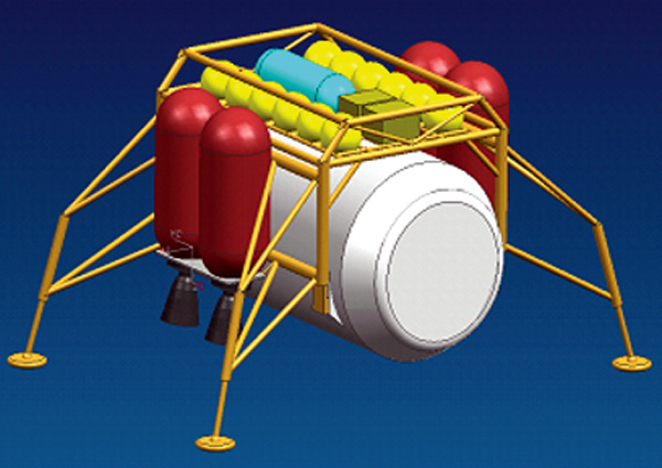
This is about as bare minimum as you can get for a Lunar mission. Yes, there is a small habitat nestled in the bottom, in the middle of the fuel tank cluster.
But there is no airlock. Instead there is a bare bones suitport. This means the space suit is outside the pressurized section with the back-pack inserted into a hole in the wall. The back pack opens like a door to allow the astronaut to wiggle into the suit. You design a vehicle with a suitport only if you are desperately short on pressurized habitat volume, short on habitat mass budget, or both. Full sized. airlocks take up lots of both.
But wait, it gets better. The ascent stage is not pressurized. Which means the crew gets to ride back into orbit wearing their spacesuits while standing exposed on a metal platform with no walls.
In the illustration, note how the reaction control jets on the long booms have little shields on them. This prevents the exhaust flames from the jets from roasting the astronauts.
LANGLEY UNPRESSURIZED CREW TRANSPORT WITH SURFACE HABITAT
This was a two-stage lander that incorporated unique,
dockable rear-entry space suits for a crew of four on an
unpressurized ascent stage. The ascent stage mission
was designed for a nominal surface stay time of 7 days,
and a return payload capacity of 100 kg).
Descent Stage
Power
The descent stage carried oxygen-hydrogen fuel cells for primary power; total peak power required by descent stage (when active) = 4.0 kW; total peak power required by descent stage (when inactive) = 500 W.
Propulsion
The propulsion system had three LOX/LH2 descent engines that operated at an Isp of 459.7 sec. The engine thrust was 31.1 kN. Oxygen boil-off was estimated to be at 1.2% per month and hydrogen boil-off was estimated to be at 4.3% per month. Descent delta-v: 1,900 m/s
Structures
The baseline primary structural material was aluminum 2024 or similar. There were two oxidizer tanks/four fuel tanks; The landing structures made up 3.3% of the total mass to be landed.
Environmental Control and Life Support System
Standard ECLSS in pressurized habitat; 13.2 m3 total habitable volume; 3.3 m3 habitable volume per crew member; 14.2 m3 total pressurized volume.
Down Payload
500 kg
Surface Stay Time
7 days
Nominal Descent and Low Lunar Orbit Loiter Duration
7 days
Low Earth Orbit Loiter Duration
95 days
Guidance Navigation & Control
RCS Cluster (x4)
Ascent Stage
Power
Ascent stage carried Li-ion batteries for primary power during ascent; total peak power required by ascent stage = 1.0 kW
Propulsion
There were four NTO/MMH ascent engines rated for operation at an Isp of 332.5 sec. The propulsion system provided a thrust of 11.1 kN. Thrusters were initially gimballed out to avoid damaging the habitat (which could be reused on a future mission or as part of an outpost). Ascent delta-v: 1,889 m/s
Structures
Aluminum 2024 or similar. There were two oxidizer tanks/two fuel tanks.
Environmental Control and Life Support System
Nominal life support was to be provided by the Extravehicular Activity (EVA) suits.
LUNOX is a concept designed by engineer Kent Joosten of the Johnson Space Center in 1993. You can find more details here, here, and here.
The basic idea was to harness the awesome might of In Situ Resource Utilization (ISRU) to dramatically cut the cost of establishing a lunar outpost.
At the time hydrogen was not believed to be readily available on Luna, but oxygen certainly was. Freaking Lunar regolith was 45% oxygen, the stuff was everywhere! There would be a fantastic cost savings if spacecraft could refuel with both hydrogen and oxygen (instead of having to transport the fuel needed to return home). But even refueling just with oxygen alone (and lugging along the extra hydrogen needed to burn it) would reduce the cost by a whopping 50%! Such is the grim mathematics of Every Gram Counts.
OK, so there is lotsa oxygen there. Can it be easily extracted? Engineer Joosten pointed to no less than fourteen methods of lunar oxygen (LUNOX) extraction are known. He favored a hydrogen ilmenite reduction technique patented by the US-Japanese Carbotek/Shimizu consortium. Joosten figured that an automated/teleoperated plant using solid-state high-temperature electrolysis could produce 24 metric tons of cryogenic liquid oxygen per year (assuming an extraction efficiency of 4% after benefication). This would require somewhere between 40 and 80 kilowatts of continuous electricity, which argues for small nuclear reactor. Such a reactor could also charge up teleoperated mining drones and supply astronauts with power when they were on site.
The plan was for a series of four uncrewed landers (on one-way trips) to deliver the lunar outpost elements. The landers are belly-landers instead of tail-sitters, in order to:
Reduce the chance of toppling over and destroying itself and the cargo when landing
Flight one delivered the oxygen extractor plant and the nuclear reactor. The reactor was on a teleoperated cart so the radioactive thing could be moved far far away from the plant. The plant just stayed in the lander.
Flight two would deliver teleoperated Loaders (to dig up regolith and transport it to the oxygen plant), Tankers (to transport the liquid oxygen produced), and Haulers (for the astronauts to use, when they arrive). All the teleoperated vehicles are electrically powered, periodically recharged by the reactor.
The loaders can collect and sort about 500 kilograms per hour of ilmenite-rich regolith.
Once the plant has produced enough liquid oxygen to refuel a crewed mission (so that the crewed mission has enough fuel to return the crew home), flights three and four will deliver equipment needed by the astronauts. There is no sense going to the expense of sending the astronaut gear if it turns out the oxygen plant or something is broken and cannot refuel the crewed mission.
Uncrewed Lander click for larger image
Oxygen Production
Loader puts regolith into Oxygen Plant's screen covered hopper. Oxygen produced is cryogenically liquefied and stored in lander's tanks. When crewed lander arrives, some of the oxygen is loaded into the tanker. Then the tanker is sent to the Phoenix crewed lander. The nuclear reactor is at a remote location, connected to the oxygen plant by long power cables. click for larger image
LUNAR OUTPOST ELEMENTS
Flight
Item
Mass (kg)
1
Lunox Plant
7,269
1
Nuclear Reactor (40-60kWe)
5,110
2
Tanker #1
1,471
2
Tanker #2
1,471
2
Loader #1
1,728
2
Loader #2
1,728
2
Hauler #1
962
2
Hauler #2
962
3
Pressurized Rover #1
5,150
4
Pressurized Rover #2
5,150
3
Mobile Power Unit #1
1,544
4
Mobile Power Unit #2
1,544
3, 4
Science Payload
2,000
5
Airlock/Node Support Vehicle
11,010
6
Logistics & Spares
12,454
Total:
59,553
LUNOX MASS BREAKDOWN
Phoenix Crewed Lander
Item
Mass (kg)
Apollo-type Crew Module
5,935
Crew and Support (x4 crew)
609
“Phoenix” Crewed Lander (4 x 31,150 KN thrust engines)
5,505
Cargo
2,000
Trans-Lunar Injection Stage (3 x RL-10-A4 engines)
6,130
ELEMENTS
20,179
Crew Module Propellant
199
Lander Propellant
16,944
Liquid Hydrogen Fuel for Return Trip
2,492
Trans-Lunar Injection Stage Propellant
43,930
PROPELLANT
63,565
TOTAL MASS IN LOW EARTH ORBIT
83,744
Lunar Oxygen Required
10,165
TOTAL MASS, INCLUDING LUNAR OXYGEN
93,909
When it is assured that the ISRU site has mined enough oxygen to refill the Phoenix spacecraft's tanks, the four astronauts board the ship and head for Luna. The Phoenix is boosted into orbit and uses a Trans-Lunar Injection Stage to send it into a trajectory to the moon. After it lands, a teleoperated tanker rover transports 10,165 kilograms of LUNOX to the crewed ship and refills its empty oxygen tanks.
Yes, the Phoenix does resemble the fictional Eagle Transporter from the TV show Space 1999. It even has the Eagle's downward pointing chin bubbles. But this is more a case of "form following function", certainly NASA engineers didn't crib spaceship design features from a scifi TV show.
The crew can now explore Luna in style, with the tons of equipment transported to the site. The two pressurized rovers can provide power, communication, thermal control, life support, and habitation for 14 days on the lunar surface. They have a minimum exploration range of several hundred kilometers. Each rover obtains mobile power and water for life support from a mobile power unit. These power units are trailers containing fuel cells. The cells produce water and electricity by combining LUNOX with hydrogen brought from Terra.
But the big advantage is the ISRU has cut the project cost in half.
After the mission and departure from the Lunar surface, upon approaching Terra the conical crew section separates and reenters the atmosphere by aerobraking much like an Apollo Command Module (which is essentially what it is). Joosten recommends designing a steerable parasail-type parachute so that the capsule can come to rest on dry land instead of the ocean, because Apollo-style splashdown and Navy water recovery is so hideously expensive. The rest of the spacecraft is aimed at a remote spot of the ocean and (mostly) burns up like a huge meteor.
click for larger image
Teleoperated tanker travels to the Phoenix landing site. There it refills the Phoenix's empty liquid oxygen tanks. click for larger image
The Mars Design Reference Architecture needed standard Mars landers, so the study authors brain-stormed many concepts and did extensive comparisons using various metrics to winnow out the top designs. I am only going to cover the top couple of landers, you can read all about the others in the report.
The lander is composed of:
Aerobraking Method: either a rigid aeroshell or an inflatable heat shield. This burns off as much velocity as possible by using Mars atmosphere instead of costly rocket fuel
Mars Descent Module (MDM): in either horizontal or vertical configuration. A rocket platform used to gently land the payload.
Payload: see here. There is one payload inventory for the uncrewed precursor landing and one for the crewed landing.
The two major differences that distinguish the designs are Aerobraking Method and Payload Orientation.
Aerobraking method can be either Mid lift-to-drag ratio aeroshell or Hypersonic inflatable aerodynamic decelerator.
Payload orientation can be either Horizontal Configuration or Vertical Configuration.
So there are four possible combinations: mid-L/D horizontal, mid-L/D vertical, HIAD horzontal and HIAD vertical. The orginal DRA used mid-L/D horizontal.
"Baseball Card" for the uncrewed Mars Lander click for larger image
AEROBRAKING: MID-LIFT-TO-DRAG RATIO (mid L/D)
Mid L/D architecture
Mid L/D event sequence
Lift-to-drag ratio (L/D) is the amount of lift generated by a vehicle, divided by the aerodynamic drag it creates by moving through the air. It tells you if your aircraft has the glide capacity of a brick.
A high L/D aircraft is like an aircraft that can glide for miles. A low L/D aircraft is like a brick, meaning it has trouble flying at all. The Apollo command module has a low L/D, it just falls ballistically and hopes it slows to parachute speeds before the heat shield erodes away.
For a Mars mission, where every gram counts, designers figured they needed to encase the lander in a rigid aerodynamic shell with a medium L/D. A high L/D shell eats up too payload mass because the shell weighs too much. A low L/D shell cannot slow the lander enough so it goes splat! and makes a smoking crater. A mid L/D is just right. Basically the aeroshell acts like a lifting body.
The lander is packed in the mid L/D aeroshell. This deorbits and aerobrakes, while steering to the designated landing site. Once it burns off enough velocity, the aeroshell is shed and discarded like a banana peel. The lander proper ignites its rocket engines and uses them to soft-land on Mars.
Advantages over HIAD: very volume efficient in the booster rocket faring since it is almost an inner layer of the faring; aeroshell can be steered right to the desired landing site.
Disadvantages compared to HIAD: HIAD has much less penalty mass compared to an aeroshell;
Aerobraking by using heat shields is tried and true technology. The trouble is that [a] heat shields are heavy which eats into your payload mass, and [b] since the Martian atmosphere is so darn thin you need an extra-wide heat shield, which multiplies the heat shield penalty weight.
The designers try to do an end run around those two problems by making the heat shield an inflatable balloon. A remarkably fireproof balloon, but a balloon none the less.
Advantages over mid L/D: has much less penalty mass since it is a balloon.
Disadvantages compared to mid L/D: deflated balloon takes up lots of room in booster rocket faring; it basically cannot be steered.
PAYLOAD ORIENTATION: HORIZONTAL CONFIGURATION
click for larger image
Horizontal configuration inside mid L/D
Horizontal configuration with HIAD (on right) packaged inside booster faring
PAYLOAD ORIENTATION: VERTICAL CONFIGURATION
click for larger image
Vertical configuration inside mid L/D
Vertical configuration with HIAD (on right) packaged inside booster faring
PAYLOAD
Uncrewed precursor landing
Mars Descent Module (MDM): This is the rocket propelled platform that lowers the rest of the payload to a soft landing on Mars. Since it would be more or less impossible to equip it with chemical engines cranking out enough delta V to land unassisted from orbit, some sort of aerobraking has to be used.
Mars Ascent Vehicle (MAV): Small rocket propelled vehicle that boosts the Mars astronauts back into orbit at the end of the surface exploration part of the mission.
ISRU plant: for certain choices of chemical fuel used by the MAV it will be possible to manufacture said fuel from the Martian atmosphere by using in-situ resource utilization equipment. As always ISRU dramatically increases payload mass since you don't have to lug all that heavy fuel from Terra. If such fuel is not used, the ISRU plant is removed from the payload inventory. Its mass is assumed to be included in the MDM mass, and it is carried as disassembled parts inside the MDM body.
Fission Surface Power System (FSPS): nuclear reactor supplying electricity to the crew habitat and ISRU plant.
Crew Surface Mobility Vehicle (Rover): some sort of Mars groundcar used to extend the range of the crew's exploration. From the illustrations it appears to be some species of NASA Space Exploration Vehicle (SEV)
Crewed landing
Mars Descent Module (MDM): as above.
Explorer Crew: four to six, depending upon the design. Study assumes each crew is 98.5 kg (largest US
male, per SSP 50005). 4 crew is 394 kg; 6 crew would be 591 kg
Crew Habitat: habitat module for the explorers to live in for the duration of the surface mission.
The ascent vehicle transports the Mars surface explorers up to the orbiting spacecraft at the end of the surface segment of the mission. In some designs it is transported to Mars without the heavy oxygen fuel, relying on the ISRU unit to generate it from the Martian atmosphere using power from the nuclear reactor.
The study looked at a 4 crew and a 6 crew ascent vehicle. To get an idea of the lower limit, they looked at a 4 crew "taxi" version. This was from a prior lunar ascent vehicle and was a spartan bare-bones design. The main difference is that the 4 and 6 crew have a life support system, the taxi does not. The 4 and 6 allow the crew to do a pre-flight check out in a shirt-sleeve environment, and use the MAV as a supplemental/back-up habitat module. Not so the Taxi, the crew will have to do check out and fly while wearing suits.
The 4 crew has a 2.35 meter inner diameter, the 6 crew has 2.7.
"Baseball Card" for 6 Crew MAV click for larger image
4 Crew MAV
6 Crew MAV
4 Crew Taxi MAV
6 crew MAV dimensions
4 and 6 Crew MAV Mass Summary Comparison
(both with life support)
4 Crew Taxi MAV Mass Summary
(no life support)
MSFC Lander Concept
MARSHALL SPACE FLIGHT CENTER LUNAR LANDER PREPARATORY STUDY PHASE II
The Phase II concept had a crew EVA hatch close
to the surface (~3 m). The minimized mass/
volume ascent stage allowed for increased payload
capability. Potential radiation protection was provided
by the propellant tanks surrounding the surface
habitat. Combining the ascent stage and surface
airlock provided increased payload capability and
allowed easier cargo stowage and unloading (only
for a sortie mission). Use of storable propellants in
the ascent stage allowed for long-term storage on
the lunar surface and potential cost and production
time savings, using high Technology Readiness Level
technology. Incremental outpost build allowed for
easier incorporation of upgrades and increasing levels
of redundancy. Cargo deployment occurred from the
middle bay. At completion of the study, dust mitigation
in the ascent vehicle/airlock still needed refinement.
Descent Stage
Power
Two H2-O2 5 kW fuel cell power plants (one primary, one backup). Fuel cells were shown to have lower system
mass than batteries in Phase 1 trade. Included 90% Power Management and Distribution (PMAD) efficiency
(4.5 kW average delivered). Two units provided redundancy and reduced mass without sacrificing crew safety.
Propulsion
Assumptions: Fuel: LH2, Oxidizer: LOX, Mixture ratio (Oxidizer/Fuel [O/F]): 6.0, Nominal Isp = 450 sec,
MPS Thrust Level, Four 44,482 N (10,000 lbf) per engine (one engine out, three operating, three
66,723.5 N per engine (one engine out, two operating), Thrust levels dictated by allowable
Thrust-to-Weight (T/W) (0.4 for crewed, 0.3 for cargo) at Powered Descent Initiation.
Telecommunications
Two S-Band transponders (descent stage for lunar communications to Earth and descent stage to EVA and other
habitats) consisted of independent strings. The Ka-Band transceiver on the descent stage was to be used for
wideband data back to Earth, with an S-Band 802 16n wireless network for lunar communications between EVA crew,
internal intercom, outpost to lunar rover, and habitat-to-habitat.
Guidance, Navigation & Control
One radar altimeter, one terrain avoidance system
Ascent Stage
Power
Two 3.5 kW fuel cell power plants (one primary, one backup). Included 90% PMAD efficiency
(3.2 kW average delivered). Reactants sized for 3-hour ascent operation with 5% residuals.
Reactants stored in gaseous state in dedicated reactant tanks.
Propulsion
MPS Engine Assumptions:
Fuel: MMH
Oxidizer: N2O4,
Mixture ratio (O/F): 1.65
Nominal Isp= 315 sec
Thrust = 15,569 N; chosen to produce Apollo-like initial ascent T/W.
Non-gimballable Main Engine, 15,569 N thrust, Propulsion system two-fault-tolerant as necessary,
designed for minimum risk.
Operating Pressures, Propellant Tanks – 1.7 MPa
Design Pressure – 2.8 MPa
Pressurant Tanks – 31 MPa down to 3.4 MPa, Helium pressurant sized for isothermal (plus 10%)
Propulsion hardware Technology Readiness Level 9, design margin on all dry mass 20%.
Telecommunications
Two S-Band transponders (ascent stage to CEV and ascent stage to Earth) consisted of independent strings.
Thermal
MLI, heat exchanger, evaporative cooling system with Coldplates
Structures
The internal equipment mass was applied evenly to the 1st and 2nd floors.
Launch loads = 5.0 g axial, 2.0 g lateral
Staging loads = 1.2 g axial, 0 g lateral
10 Hz minimum frequency.
Isogrid cylindrical habitat walls and interior 2nd floor.
The panel material was Al Li 2195; the beam material was Al 7075.
The major objective of this lander design was to propose an ascent stage/airlock combination with the smallest
possible vehicle mass that could still accomplish the required mission phases. This, along with minimizing
the descent stage structure, allowed the largest possible payload to be delivered to the lunar surface for
the given launch vehicle capability. Another design goal was to reduce the height of the surface access port
(i.e., the airlock hatch). Finally, a common lander was designed to accomplish three separate missions: crewed
sortie, crewed outpost, and unpiloted cargo delivery. These considerations led to the lander configuration in
the figure above.
The Marshall Space Flight Center (MSFC) team, which consisted of members from Johnson Space
Center (JSC), Glenn Research Center (GRC), and Ames Research Center (ARC), developed several lander
configurations. The study review board chose one of these for further study. The selected concept is depicted
above. For those who are familiar with the Apollo lander, the most distinguishing features of this design are the
large propellant tanks that surround the vehicle and the side-mounted ascent stage. Interior to the six large
propellant tanks is a cylindrical surface habitat.
Concept of Operations
Lander/CEV configuration.
This lander is launched on top of the Cargo Launch Vehicle (CaLV) into
Low Earth Orbit (LEO) without its crew. The crew is launched separately
on the Crew Launch Vehicle. The crew, in their Crew Exploration Vehicle
(CEV) capsule, meet up with the lander in LEO. The CEV connects to the
top of the lander, directly to the surface habitat (see figure). The crew then
has access to the lander’s habitable volumes during the remainder of the
mission to the Moon. Once in Lunar orbit, the two ships undock, and the
lander and her crew descend to the lunar surface while the CEV remains
unpiloted in lunar orbit.
Minimized Ascent Stage
Crew in Habitat and airlock/ascent stage.
In the Apollo mission, the one habitat on the lunar lander functioned as
living quarters, airlock, and ascent vehicle. A separate habitat became
desirable with a larger crew of four and a longer surface stay of 7 days.
The driving factor in the design of this vehicle was the mass of the ascent
vehicle. Every kilogram/pound of ascent vehicle costs 0.8 kg (1.8 lb) of
cargo that could have been carried down to the surface. Therefore, to
maximize the number of science instruments and equipment that could be carried, it was necessary to minimize
the mass of the vehicle that brought the crew back up to lunar orbit after their surface mission was complete.
To do this, the physical size of the ascent vehicle was limited to the smallest diameter that could safely
carry the four crew members and allow them to function during ascent. It will be a snug fit, but with a nominal
ascent duration of only 3 hours, the small sacrifice in luxury is worth it. The ascent vehicle weight came in at
just over 5 mt (11,000 lb), almost equivalent to that of the Apollo mission, but carries four crew members
instead of two. Being similar in size to the Apollo ascent “cab” allows for an engine in the same thrust class as
Apollo’s engine. This heritage and experience base will be valuable when developing the rocket engines for the
next-generation landers.
In another effort to minimize vehicle weight and maximize cargo carrying
capability, the ascent vehicle is mounted on the side of the lander and
doubles as the airlock – a notable feature of this concept. If there was not a
separate airlock (as with the Apollo lander), the entire habitat volume would
have to be depressurized every time an Extravehicular Activity (EVA) was
needed, with precious air being lost to the vacuum of space. This would
also require all four crew members to be suited up before depressurization.
It is much less wasteful to have a small airlock for two crew members to
leave and enter the vehicle without depressurizing the entire habitat. This
airlock/ascent stage is shown in the figure and depicts possible locations
of crew members in the surface habitat and the airlock/ascent stage. By
mounting the ascent stage/airlock on the side of the vehicle, the structural
loads are reduced (it is not in compression due to the load from the large
CEV during the Trans-Lunar Injection and Lunar Orbit Insertion burns), and
the surface access hatch is much closer to the surface. This configuration
allows the hatch to be approximately 3 m off the surface, which is
slightly lower than the Apollo lander.
Subsystems
Home on the Moon.
Although the Lunar Lander Preparatory Study (LLPS) lander is three times larger, the structure mass is
only 60% heavier due to selection of this configuration, propellant choice, and numerous other innovations
(including materials). This savings in structure mass contributes to larger LLPS lander payload delivery.
The six main propellant tanks provide LH2 and LOX to the lander’s main propulsion system. This is the same
propellant that was used by the Space Shuttle’s main engines. The LH2/LOX combination is one of the most
fuel-efficient rocket propellant mixes available (on a “miles-per-gallon” basis). This propellant combination is a
cryogenic fluid, requiring refrigeration-like measures, compared to the Apollo storable hypergolic propellants,
and therefore requires thermal management to maintain the LOX and LH2. This thermal management involves
the use of passive measures, namely Multi-Layer insulation (MLI) and spray-on foam insulation. Both Apollo’s
and this concept’s higher technology use 5% of the lander’s total mass for the propulsion subsystem.
The power, control, and avionics subsystems are both dramatically updated for the new lander. One example
is the three orders of magnitude (or more) greater memory storage on the four flight computers (total on both
stages) with three CPUs per computer. Proton Exchange Membrane (PEM) fuel cells are baselined as the power
source for both the descent stage and ascent stage vehicles. These fuel cells are similar to the fuel cells that
were used to power the Space Shuttle, but include many more advanced technologies. The fuel cells generate
power by converting hydrogen and oxygen into water. The water produced during this process can then be
used by the astronauts. The rest of the Power Management and Distribution (PMAD) equipment is based upon
both off-the-shelf components and historical data for NASA spaceflight systems. The avionics design focused
on the following four major areas: Communication & Tracking, Command & Data Handling (includes the flight
computers), Displays and Controls, and Guidance, Navigation & Control. One notable feature of this concept is
an S-Band wireless network for communication with the crew during Moon walks. The descent stage also has
a wideband transceiver to send data such as video back to Earth. The Displays and Controls design includes
controls that can be operated with gloved hands and operate in a vacuum in the event of depressurization.
Each stage has two sets of displays and control panels. The ascent stage also has two sets of hand controllers
for manual control of the spacecraft.
The ascent stage was investigated to determine if it had enough volume to accommodate four crew members
(in modified ACES suits) during descent and ascent and two crew members in larger EVA suits during the lunar
stay. The don/doff operation appeared feasible within the given cabin dimensions, but additional clearance
between the knees and shoulders was needed to reduce the chance of crew and/or suit injury from bumping
into wall-mounted avionics boxes. Therefore, a “keep-out zone” between the knees and shoulders was cleared
of avionics boxes and other obstructions to provide
clearance for the two crew members to doff and don
the EVA suits. Environmental Control and Life Support
System (ECLSS) atmosphere revitalization in the surface
habitat includes a combined cabin and suit loop that
provides CO2 removal, atmosphere trace contaminant
control, sensible heat rejection, and atmosphere
humidity removal. An additional feature of this ECLSS
design is its scarring such that eventually, if this lander
becomes part of an outpost, CO2 and water vapor could
be recovered for closed-loop oxygen and water recovery
rather than being vented overboard. Avionics and crew
metabolic waste heat as well as environmental loads are
thermally collected inside the descent and ascent stages
and rejected through a fluid loop using radiators located
on the descent stage.
Mobility
MULE.
The next people to go to the Moon will eventually live
and work for 6 months at a time from a central outpost.
NASA’s new lunar landing spaceships will bring people,
supplies, and equipment to the lunar base. As with
campers that drive their RVs across country then
set them up in a campground as their home
away from home, the lunar explorers will set the
landers down on the surface then move them
over land to the base. The figure on the previous
page shows an example of a lunar base.
Due to navigation safety and the rocket nozzle
exhaust ejecta damage problem, landers must
set down at remote zones approximately 2 km
from the outpost. The landers must
then be moved to the outpost using a set of
robotic transports. A set of four Mobility Utility for
Lunar Exploration vehicles (MULEs) are used to
accomplish this task (see next figure). MULEs,
currently being studied by engineers at ARC, in
California, are slightly smaller than golf carts and
have a mass of 500 kg. Power is supplied by Li-Ion batteries that can be recharged from the outpost’s
central power station. MULE speeds range from 1 to 3 kph. Even at these low speeds, lander
transportation can be accomplished within half the time allocated for a standard 8-hour EVA.
Conclusions
This lander concept provides a minimum mass ascent stage, necessary for maximizing surface payload, and
combines ascent stage and airlock functions. This design accomplishes the three separate missions with total
lander masses of 45 mt for the crewed sortie and outpost missions and 53.6 mt
for the cargo deliver version. The delivered additional payloads for the separate tasks are 1.7 mt for
the sortie case, 8.8 mt for the crewed outpost mission, and 20.5 mt for the uncrewed
cargo lander. Also, the proposed MULE concept provides an efficient method of satisfying the lunar outpost
mobility requirements and can be easily adapted to fit a variety of lander concepts.
The Mars Excursion Module is from a 1966 study by North American Rockwell. This was the first Mars lander designed after the bombshell from Mariner 4 that astronomers had drastically over-estimated how dense the Martian atmosphere was. They had figured it was a useful 85 hectopascals (hPa), in reality it was an almost worthless 6 hPa (just slightly better than a vacuum). By way of comparison Terra's atmospheric pressure at sea level is 1013 hPa.
The poor prior design that was rendered obsolete by the low atmospheric pressure was the Aeronutronic MEM
The low atmospheric blow Mariner 4 dealt to the scientist was just the cherry on top of the sundae. Much more serious was the photographs. The scientists knew there could be no chance of images of scantily-clad Barsoomian princesses, but they were hopefull there would be some lakes and maybe even a canal or two. But nothing but a bunch of freaking craters? The scientists got a sinking feeling in their stomachs, as they could almost see the Mars exploration program go swirling down the toilet right before their very eyes. Once the taxpayers saw these photos the NASA tax dollars would dry up. Mars looks like the freaking moon, for cryin' out loud! And NASA has already been to the moon. Been there, done that, got the T-shirt. No need to go to Moon part deux.
But NASA put a brave face on things, and proceeded to plan for a Mars mission anyway. Sadly, they were right. As I write this it is fifty years later and the movie The Martian is still science fiction, not a documentary. That furry "whumph" noise you hear is RocketCat doing a facepalm.
Given the pathetic whisp of Martian atmosphere, NAR went with a classic gum-drop shape much like the Apollo command module for aerobraking purposes. For one thing all the expertise obtained from Apollo could be leveraged. Plus there was Terra's atmosphere conveniently located for heat shield test purposes.
Though I did read a recent report suggesting that even with the gum-drop design the Martian atmosphere is not up to the task of aerobraking the MEM before it splats into the ground at hypersonic velocities. The report suggested that entirely new technologies are needed.
In a genius move, NAR made the design modular. If you needed a lean and mean mission, you could remove some internal compartments, ascent propellant, and surface supplies to get the total lander mass down to 30 metric tons. Or you could max it out. Or anything in between.
The price of a low mass lander is that it could only support two crew for four days, and the mothership had to be in a low circular Mars orbit for both departure and return to the mother. The high mass lander needed lots more delta V from the mothership, but it could support four crew for thirty days, and the mothership could be in a high elliptical Martian orbit.
You can also make a lander with no ascent stage at all. This can be used to land supplemental equipment, such as an extended-stay shelter, nuclear power module, or a huge Mars mobile lab with fuel supply.
From Definition of Experimental Tests for a Manned Mars Excursion Module NAS9-6464 (1967)
MEM has a mass of 49,437 kg when it separates from the mothership. The deorbit motors fire for about 200 m/s ΔV. Deorbit motor has a thrust-to-weight-earth of 0.4. The MEM starts falling out of orbit, and the deorbit motors are jettisoned. The MEM now has a mass of 46,078 kg.
The MEM enters the Martian atmosphere at an angle of attack of 147°. It starts aerobraking, subjecting the crew to about 7 g's. When it slows to a mere Mach 3.5, it pops a hypersonic drogue chute to stabilize then inflates a 18 meter diameter ballute. This will slow the MEM down to Mach 1.5.
Once the MEM lowers to 3 kilometers of the surface, it jettisons the ballute. The plug in the heat shield over the descent engine is jettisoned. The descent engine is canted about 13° off center, because the MEM center of gravity is off center, because due to design consideration the MEM is not radially symmetric. Mostly because of that pesky crew quarters and laboratory.
The conical section of the heat shield is jettisoned. The descent engine ignites and burns for 1,070 m/s to 1,450 m/s ΔV, depending upon whether the mothership was in a circular or elliptical orbit when the MEM detached. At this point the engine will have a thrust-to-weight-earth of 1.5 to 0.15.
The design managed to squeeze in enough extra propellant for about two minutes of hovering (about 457 m/s of ΔV). Which could be a life-saver if the landing site unexpectedly turned out to be full of jagged boulders or something. Instead of hoving, the extra propellant can move the MEM laterally about 6.7 kilometers to an alternate landing site. The design had six landing legs. In concert with the incredibly stable gum-drop shape, they could manage a ground slope of up to 15°. Actually the shape is similar to a no-spill coffee mug, and for the same reason.
The crew then frantically does as much Martian scientific research as they can cram into 30 days. The pressurized volume is 21.6 m3 (14.4 is laboratory/living quarters, 7.2 is ascent capsule). 20% is taken up by equipment, leaving barely 4.3 m3 per crewperson (right at the ragged limit before claustrophobia strikes).
When it is time for departure, the descent stage becomes the launch pad (which stays behind on Mars), and the center becomes the ascent stage. It brings the crew and 136 kilograms of Martian geological samples back to the orbiting mothership. It launches as Ascent Stage I.
When the Stage I tanks run dry, they are jettisoned. The ascent stage continues as Ascent Stage II. The two stages have a combined ΔV of 6,200 meters per second. The ascent has five components.
Initial burn to 19 kilometer altitude (mothership circular: 4,206 m/s ΔV, mothership elliptical: 4,286 m/s ΔV)
Coast to 185 kilometer altitude
Burn to circularize orbit (23 m/s ΔV)
At appropriate time, burn to ascend for rendezvous (mothership circular: 168 m/s ΔV, mothership elliptical: 1,327 m/s ΔV)
Rendezvous with mothership at apoapsis
Total ΔV: mothership circular 4397 m/s, mothership elliptical 5,635 m/s
The ascent stage docks with the mothership using its Reaction Control System (RCS). It has 100 meters per second of ΔV left for the docking at this point. The rest was burnt during the descent and ascent phases.
The deorbit motors are the knot on the bottom.
The descent engine is temporarily hidden behind the plug in the heat shield. The engine is tilted about 13° off center. It is fed from fuel tanks in the descent stage.
The ascent stage I is the external tanks. Their fuel is burned through the ascent stage II engine. When the stage I tanks run dry, "staging" is by jettisoning the tanks.
The ascent stage II is the internal tanks and the engine at the bottom.
From Final Report: Propellant Selection for Spacecraft Propulsion Systems, Volume II Missions and Vehicles (1968)
The deorbit stage uses a beryllium solid rocket fuel with a specfic impulse of 300 to 325 seconds, a thrust of 133,500 to 204,600 Newtons, and a burn time of 48 seconds.
The space shuttle used a more modern mix of monomethylhydrazine fuel with nitrogen tetroxide oxidizer. Still toxic but nowhere near as bad. It also has a specific impulse of 336 seconds.
The one joker in the deck was the specified fuel for the descent and ascent stages. It seems they couldn't quite get the ΔV they needed out of conventional liquid oxygen (LOX) and liquid hydrogen (LH2). With the mass ratio the design had (i.e., the tiny fuel tanks), LOX/LH2 could not even manage the 4,880 m/s ΔV required to reach the mothership in a low circular orbit, much less the 6,200 m/s ΔV required if it was in a high elliptical orbit. The problem was that LH2 takes up a lot of room, but the MEM's fuel tanks are cramped. There wasn't room for enough LH2 even if the entire area was converted into one gigantic tank.
So they used FLOX and liquid methane (CH4) instead. That can do 6,200 m/s ΔV easy because liquid methane is more than six times as dense as liquid hydrogen. So you can cram six times as much liquid methane mass into the same sized tanks. Using FLOX instead of LOX makes up for the lower energy in methane. FLOX/CH4 has a specific impulse of 383 seconds, compared to LOX/LH2's specific impulse of 449 seconds. LOX/CH4 is lucky to get a pathetic 299 seconds.
What is FLOX I hear you ask? Why, just a simple mixture of liquid oxygen, and Liquid Fluorine.
Fluorine is beyond insanely dangerous. It is incredibly toxic, and will corrode almost anything (some explosively). They don't call it "The Gas of Lucifer" for nothing. The pious hope of the MEM designers was to contain the FLOX in tanks lined with nickel or something similar that would form a passivation layer.
The FLOX mix is 82.5% fluorine and 17.5% oxygen. Mixing liquid fluorine and liquid oxygen is actually relatively safe. For some odd reason those two will not chemically combine without some coaxing. If they do combine, however, you get the dreaded compound Dioxygen Difluoride. This is the compound with the chemical formula FOOF, which coincidentally is the sound your laboratory will make as it blows up. This is the most famous compound in Derek Lowe's hysterical list of Things I Won't Work With (take a minute to read it, the article is a scream).
Another concern is that in a tank the fluorine and oxygen might separate. Then the engine would periodically be sucking pure fluorine, which certainly will not be doing the engine any good.
Carrying entire tankfuls of ultra-corrosive flaming explosive death to Mars seems to be a questionable decision, to say the least. If the MEM lands a trifle hard and the tanks rupture, you won't have the basis for a re-make of The Martian. More like a large melted crater with a few odd pieces of corroded metal and polished skeleton bits at the bottom.
At least the MEM designers saved mass on the ignition system. You don't need any. FLOX/CH4 is hypergolic (because fluorine is hypergolic with almost anything). This is also a help when the ascent stage does staging, you can easily re-start the engines in mid-flight.
I'm doing more research, but apparently the MEM design is so popular, that it was later redesigned just a bit to remove the need for liquid fluorine oxidizer. This would involve removing equipment and increasing the size of the fuel tanks.
From Definition of Experimental Tests for a Manned Mars Excursion Module NAS9-6464 (1967)
The bent horizontal cylinder next to the crewperson is the laboratory/living quarters.
Artwork by Les Bossinas of NASA's Lewis Research Center (1989)
From Final Report: Propellant Selection for Spacecraft Propulsion Systems, Volume II Missions and Vehicles (1968)
Click for larger image.
From Final Report: Propellant Selection for Spacecraft Propulsion Systems, Volume II Missions and Vehicles (1968)
From Definition of Experimental Tests for a Manned Mars Excursion Module NAS9-6464 (1967)
The descent engine (blue) is canted about 13° off center, because the MEM center of gravity is off center, because due to design consideration the MEM is not radially symmetric. You can see the asymmetry above. The blue circle with the astronaut in it is the laboratory/crew quarters, it is lighter than the green tank on the opposite side.
From Final Report: Propellant Selection for Spacecraft Propulsion Systems, Volume II Missions and Vehicles (1968)
Click for larger image.
From Final Report: Propellant Selection for Spacecraft Propulsion Systems, Volume II Missions and Vehicles (1968)
Click for larger image.
From Final Report: Propellant Selection for Spacecraft Propulsion Systems, Volume II Missions and Vehicles (1968)
Click for larger image.
Detail
Artwork by Tom Peters
click for larger image
Detail
Artwork by Tom Peters
click for larger image
Detail
Artwork by Tom Peters
click for larger image
Detail
Artwork by Tom Peters
click for larger image
Logistics Lander.
From An Initial Concept of a Manned Mars Excursion Vehicle for a Tenous Mars Atmosphere by G. R. Woodcock NASA TM X-53475 (1966)
Nuclear Power Module.
From An Initial Concept of a Manned Mars Excursion Vehicle for a Tenous Mars Atmosphere by G. R. Woodcock NASA TM X-53475 (1966)
Extended-Stay Shelter.
From An Initial Concept of a Manned Mars Excursion Vehicle for a Tenous Mars Atmosphere by G. R. Woodcock NASA TM X-53475 (1966)
North American Rockwell PEM
These are from Technological Requirements Common to Manned Planetary Missions: Appendix D by the space division of North American Rockwell (1965). They detail a s family of Planetary Excursion Modules (PEM).
Here I will focus on the retrobraking PEMs, that is, the ones that use retrorockets to land because the target planets have no atmosphere to allow aerobraking. These particular PEMs were intended for landing on Ceres, Vesta, Ganymede and Mercury. They are based on the Apollo Lunar Excursion Module with an Ascent Stage on top of a Descent Stage. They are designed for a 30 day stay on the planetary surface, before returning to orbit.
They do, however, have Rockwell's fixation on using the insanely dangerous FLOX as an oxidizer, and the only somewhat dangerous Monomethylhydrazine (MMH) as fuel. The reason is that liquid hydrogen requires preposterously huge tanks, but if you use anything else the specific impulse goes way down. Unless you take the mad-scientist step of using FLOX oxidizer to make up for it.
In the diagrams below, the Ascent Stage is pink, the Descent Stage is green, and the mission crew quarters is gold.
3-Crew Ceres-Vesta PEM
click for larger image
North American Rockwell 3-Crew Ceres-Vesta PEM
Total Wet Mass
14,036 kg
Descent Stage
Descent Dry Mass
9,000 kg
Descent Wet Mass
11,350 kg
Descent Propellant Mass
2,350 kg
Propulsion
Chemical FLOX/MMH
Propulsion Isp
333 s?
Descent Engine Thrust
8000 N (835 kg-force)
Descent Engine Mass
1.85 kg
Ceres Gravitational Acceleration
0.28 m/s2
Descent Start Acceleration
2.0 Ceres gravities
Ascent Stage
Ascent Dry Mass
2,280 kg
Ascent Wet Mass
2,686 kg
Ascent Propellant Mass
406 kg
Ascent Engine Thrust
3,780 N (384 kg-force)
Ascent Engine Mass
0.85 kg
Ascent Cabin Volume
6.3 m3
Ascent Cabin Diameter
2.44 m
Ascent Cabin Long
1.83 m
Crew Quarters Volume
14.0 m3
Crew Quarters Diameter
2.44 m
Crew Quarters Wide
3.96 m
Airlock Volume
1.1 m3
Airlock Diameter
0.915 m3
Crew Quarters Volume (inclu. airlock)
15.1 m3
Total Crew Volume
21.2 m3
Consumables (30 day, 3 crew)
MMH
54.4 lbs/ft3
FLOX
90.0 lbs/ft3
Nitrogen
12.30 ft3 295 kg
Oxygen
10.00 ft3 325 kg
Water
8.86 ft3 244 kg
Food
5.63 ft3 175 kg
The mission crew quarters is merged with the ascent stage. Note the Descent Stage Dry Mass does not include the mass of the ascent stage.
white payload module can be lowered directly to the ground
The Schafer LSAM used an undercarriage payload
position for its cargo lander configuration, which was
also referred to as the “bottom loader” configuration.
With this arrangement, a payload could be lowered
to the surface independent of any other system (i.e.,
no cranes required).
For example, a single, large
payload pod, such as the cylindrical module (shown in
illustration above), could be lowered directly by hoists
and cables or other mechanisms using gravity. Other
payloads might be wheeled vehicles that could be
lowered for immediate drive-away operations.
This lander could be made to accommodate a
horizontal or vertical position inside the launch vehicle
shroud, depending on the length of the payload.
Landing legs were to be folded under the frame when
packaged (not shown). RCS thrusters (not shown in
the illustration above) could be sized to assist in
engine-out operation (i.e., multiple, oversized RCS
thrusters in the nadir position).
Another advantage to
this design was that the tanks would be nearly empty at
touchdown, which provided the benefit of a very low
center of gravity.

 Assuming your spacecraft is not a freaking torchship, a Mars expedition with the entire spacecraft landing then lifting off is going to demand about ten times as much delta V than it has to spend. This is why pretty much all NASA designed crewed Mars missions have the main spacecraft loiter in orbit while the explorers use a tiny Mars Excursion Vehicle (a "lander") to ferry them to and from the surface.