These are some spacecraft designs that are based on reality. So they appear quite outlandish and undramatic looking. In the next page will appear designs that are fictional, but much more breathtaking. Obviously the spacecraft on this page are all NASA style exploration vehicles, they are not very suited for interplanetary combat (well, most of them at least).
Many of these spacecraft have a table of parameters. You can find the meaning of many of them here. Numbers in black are from the documents. Numbers in yellow have been calculated by me using the document numbers, these might be incorrect.
Hariven-class Free Trader
This is not actually "real", but the science is admirably hard.
PUTTING THE TRAMP IN TRADER
“It’s a steel box.”
“It’s a fully functional – well, mostly functional, but all primary systems are functional – Hariven-class free trader. Just what you want when you’re starting out in this business.”
“It’s a steel box with a plasma torch welded on the back.”
“And a generous cargo capacity for its displacement, regenerative life support, ah – adequate crew quarters and food vats, and docking room for a single surface-orbit shuttle.”
“And it’s –”
“– a steel box, yes. If you wanted to pay for stylish, would you be shopping for starships in a wreckyard?”
“Show me the contract again.”
(Sadly, they were imagining something like Vaughan Ling’s Planetes-inspired debris collector with comparable dimensions, capacity, etc. Sorry to say it, but that ship? Had some style. The Hariven? Really doesn’t.)
HARIVEN-CLASS FREE TRADER
Operated by: Desperate free traders, just starting-out bands on tour, your sketchy brother, refugees, space hobos, and anyone else who can’t afford a better ship.
Type: Basic freighter.
Construction: Under open-source license; produced by multiple manufacturers, most of whom would prefer not to admit it, along with various backyard fab shops.
(And when I say “desperate free trader”, I don’t mean, say, the people who fly around in a Firefly-class in Firefly. Those people, in this verse, own something like a Kalantha-class. This is down from there at the true ass end of space travel.)
Length: 46m, of which 30m is the hold.
Beam: 8m (not including radiators)
(This assumes you’re following the typical regulations which require – since the Hariven has no AI, and only dumb automation – that at least one qualified person be on watch at all times, hence a minimum of three. In practice, a Hariven can be flown by one and very often is, if they don’t mind violating the rules of navigation of every halfway sane polity in space.)
Drive (typical; may vary from build to build): Nucleodyne Thrust Applications “Putt-Putt” fusion pulse drive.
Propellant: Deuterium pellets. (dirty D-D fusion)
Cruising (sustainable) thrust: 0.6 standard gravities (0.56 g)
Peak (unsustainable) thrust: 1.2 standard gravities (1.12 g)
Delta-v reserve: (Not yet calculated, but limited; if you’re flying a Hariven, you ain’t going brachy unless you devote a lot of your hold space to extra tanks. Be prepared to spend much of your voyage time on the float.)
Maximum velocity: 0.02 c (based on particle shielding)
Not supplied as standard, but a common as-supplied variant adds a partition to convert part of the forward hold into a bay with docking clamps suitable for many surface-to-orbit vehicles.
DESCRIPTION
It’s a classic tail-lander layout of the crudest form: a 30m steel box welded on top of an 8m steel cylinder welded on top of a cheap fusion pulse drive, the latter two surrounded by pellet containers. It couldn’t look more brutalist/functional if it tried. At least most Hariven owners try to give it a bright paint job.
The hold is up front, a big steel box roughly the size of eight standard shipping containers. (Indeed, sometimes it’s made from eight standard shipping containers.) Putting it right for’ard has the advantage of simplifying construction greatly – all the machinery is at one end – and giving Hariven captains the assurance that if they ram their junker into anything accidentally, at least there’s 30m of other stuff between them and whatever they hit.
The hold opens up along its entire length on the port side to permit access. Responsible captains who convert their Hariven for passenger transport (the aforementioned touring bands, refugees, and space hobos, for example) by attaching deck partitions inside the hold and adding canned air have these welded shut. Less responsible captains simply pray for a lack of wiring faults.
The habitable section (the cylinder at the back) is wrapped in auxiliary engineering machinery and fuel storage, to the point that it’s only 4m in internal diameter. (If you need to fiddle with most of the engineering systems, you’re going to need a drone, or to take a walk outside.) It’s divided into four decks, from the bow down:
The bridge, which shares space with most of the avionics;
A small living area, which contains the foodvat, a tiny galley, the inner door of the airlock, and any luxuries you see fit to squeeze in there. Like chairs;
The crew quarters, which means four vertically-mounted sleep pods, and maybe room for another luxury or two if they’re small;
And a tiny workshop, for any repairs that need doing.
That all sits right on top of the shadow shield and the business end of the drive. If you need to adjust anything below that – well, hope you brought a drone.
But enough of this. You buy this ship, treat her proper, she’ll be with you the rest of your life.
Ain’t sayin’ how long that’ll be, mind.
Ru said:
Not that long ago, I spent quite some time running the numbers on fusion-pulse torch drives, and working out various performance figures and limitations. It was all quite informative and interesting. You haven’t given nearly enough information about the ship (eg. dry mass) or the engine (exhaust velocity ranges, reaction mass) for me to hazard a guess at its parameters, so it’ll be interesting to see what else you have for us…
There’s a lot of steel mention in its design. Sounds pretty heavy. Also, metal shells plus charge particle radiation equals bremsstrahlung delight (meaning crew will be constantly irradiated by deadly x-rays) (and it makes for a poor neutron shield, which this sort of drive badly needs). Carbon is probably easier to come by, and much easier to push around.
You don’t mention reaction mass, but with those performance figures you won’t be using pure fusion for peak acceleration. Presumably the drive expends additional deuterium for that purpose (though lithium might be a better choice).
You’re using pure deuterium fusion, but that’s a terrible choice for spacecraft fuel, really. For flights much less than the half-life of tritium, D-T offers easier ignition, lower neutron flux and more charged particles to thrust against. D-3He would be the fuel of choice, but if you want stable and conveniently mineable fuel p-6Li or p-11B would be a much better choice than pure deuterium.
Delta-V reserves for even a fairly conservative fusion spacecraft design are pretty generous. You might not be tooling around at cruising speed for long, but it should be able to sustain a centigee for weeks (or even months if the drive is good enough) at a time with a 3 or 4:1 wet to dry mass ratio.
(on reflection, I am of course wrong that D-T offers a lower neutron flux or a higher proportion of charged reaction products than D-D, but it does offer a significantly lower x-ray output and a higher exhaust velocity)
Alistair Young said:
Ah, but you’ve got to bear in mind the target market, and therefore the design paradigm. If this were higher up the scale of starships, it’d have all the fancy carbon-composite hulls, high-efficiency fuel blends, etc., etc., one could possibly desire. It’s steel, though, because it’s designed to be repaired – and in some cases, even built – by a monkey with a wrench, a backyard welding kit, and duct tape, not by professional yard dogs with all the nanowhatsits in the catalog. (Same reason the neutron protection is a slug of paraffin in the lower hull space rather than proper formed HICAP.) Likewise, it uses D pellets to power an old-style fusion pulse drive rather than D-He3 slush to power a new-style fusion torch because that drive needs much less maintenance, any backplanet schmuck can separate deuterium from water, and the calibration is rough enough that in a pinch, you can stuff just about anything that’ll fuse in there and it’ll mostly work for a while. (Basically, you want to picture the spacegoing equivalent of the beat-to-hell jalopy that’s been driven around the rainforest for forty years, being fixed with banana peels and duct tape and occasionally run on rough home-cooked rum when gas was short. It’s a sh*tbox, but it’s a sh*tbox that’s hard to kill by design.)
Again, there were several spacecraft designs that all wanted to use the name "Helios", which is confusing. Almost as many as the designs who all want to use the name "Orion."
This Helios is closely related to the Project Orion designs, in as much as they both used tiny nuclear bombs as propulsion. Sadly the Helios concept had some fundamental design problems that it never overcame.
The basic idea was created by visionary Dandridge Cole who was then working at the Martin corporation. Mr. Cole was unaware of the nuclear-shaped-charge innovation, so he thought the Project Orion design was wasting 90% of the bomb energy. He figured he could do better than that. The more you surround the bomb, the less energy you will waste. Since most material objects fare poorly when hit by a nuclear blast, Mr. Cole used three strategies:
The reaction chamber surrounding the bomb was given a huge radius. This spreads the ravening energy of the blast over more chamber wall area, so each square meter of wall has to deal with a smaller portion of the total blast. Keeping in mind that when he said "huge", he wasn't fooling. The first design had a reaction chamber diameter of a whopping 40 meters (130 feet).
The bombs were much weaker than the Project Orion pulse units, so the total blast was less. Project Orion units were 1 kiloton, Helios units were 0.01 kiloton, or one hundred times weaker.
390 kilograms of water propellant was injected into the chamber prior to each bomb. The pious hope was that the water would soak up the blast and go shooting out the exhaust nozzle at high velocity, instead of the chamber walls. Hopefully the water would also cool off the chamber walls so they wouldn't melt.
The Cole model I had engine performance that can be charitably described as "disappointing". Specific impulse was 931 seconds, which is in the upper range of conventional solid core nuclear thermal rockets. At one pulse per second the engine had a thrust-to-weight ratio of only 0.25, enough to land on Luna but not enough to lift-off from Terra. By comparison small first generation Project Orion ships were expected to have a specific impulse of 2,500 seconds and a thrust-to-weight ratio of at least 4.0.
One little inconvenient detail that Mr. Cole glosses over is the problem with tiny nuclear bombs. You see, fission reactions have that tiresome "critical" mass requirement. Meaning that if you use less than the critical mass there will be no fission chain reaction. The problem is that a critical mass of uranium-235 or plutonium will ordinarily make a much bigger bang than 0.01 kiloton. Damping the bomb down to 0.01 kiloton means that most of the uranium or plutonium does not enter the reaction. Instead they are merely volatilized into glowing radioactive vapors of death and spread to the four winds at high velocity. This makes it difficult to get permission to launch this monster from Terra's surface.
Even ignoring the radioactive contamination the inefficient use of fissionables is unconscionable. Weapons-grade uranium and plutonium are monstrously expensive, and this design will use tons of the stuff.
Cole Helios Model I
A more ambitious (and utterly insane) version was Cole's nuclear pulse jet. This would be a titanic airbreathing version that utilizes Terra's atmosphere as propellant until the ship climbs into space. The radioactive fallout would be only slightly less horrific than that from Project Pluto. The difference was that Pluto was supposed to be a weapon.
Cole Nuclear Pulse Jet
Cole Nuclear Pulse Jet
Cole Aldebaran The wet mass would be 45,000,000 kg. Specific impulse of 3,000 seconds. Propellant fraction of 0.7. Payload mass of 27,000,000 kg. Or it could soft-land a smaller payload mass of 20,000,000 kg on Luna. Air vents indicate it uses atmospheric gas for at least part of its reaction mass. Artwork by Roy Kerswill.
click for larger image
Artwork by Roy Kerswill.
click for larger image
Cole and the Martin corp stopped working on the concept in the early 1960s, because of the lack of interest on the part of the USAF, NASA, and Martin higher management. There were a few amusing "artist conceptions" of the concept created by the advertising department of other aerospace companies that wanted to appear new and trendy.
Stupid public-relations Cole Helios drawn by somebody who knew more about Buck Rogers comics than they did about real engineering
Space Sphere (1960)
Apparently based on Cole Helios Model I
Artwork by Robert McCall
unknown artist (1966)
AMERICAN BOSCH ARMA CORP HELIOS
Artwork by Frank Tinsley (1960)
ATOMIC PULSE ROCKET
American Bosch Arma Corporation
This is the Atomic Pulse Rocket, a pot-bellied space ship nearly the size of the
Empire State Building, propelled by a
series of atomic blasts.
The enormous rocket (weighing 75,000
tons fully loaded) is designed to leave
Earth with a thrust of 100,000 tons. Altogether a thousand atomic blasts—each
equal to 1,000 tons of TNT—are fired
from a low velocity gun into a heavy steel
rocket engine at a rate of one per second
until the vehicle leaves Earth's atmosphere. Then steam and vaporized steel
maintain the thrust. After transit speed
is reached, and the propulsion system
shut off, power is provided by solar batteries plating the wing and body surfaces.
Inside the rocket. living quarters are
situated in the rim of a pressurized wheel-like cabin which revolves to provide artificial gravity. Radio and radar antennae
revolve with it. Tubular hydroponic
"gardens" on either side of the rim grow
algae to produce oxygen and high protein food.
The Atomic Pulse Rocket could transport payload to the Moon at $6.74 per lb.,
less than one quarter the prevailing air
freight charges over equivalent distance.
A similar project is past the pilot-study stage in the Defense Department
(ed note: This is vaguely based on the Cole study, but is more public relations than a real engineering design study)
Helios Nuclear Pulse
Wet Mass
680,000 kg
Payload Mass
91,000 kg
ΔV
18,000 m/s
Chamber Dia
9.2 n
Propellant per pulse
100 kg
Pulse Rate
1 per 10 sec
Pulse Unit Mass
32 kg
Helios Nuclear Pulse
In 1963 the Lawrence Radiation Laboratory started working on their own version under the name of Project Helios. This was for a crewed mission to Mars. Mass in low Earth orbit (IMLEO) was to be 680,000 kg, delta-V of 18,000 m/s, delivering a 45,000 kg Mars lander into Mars orbit (total payload 91,000 kg).
The reaction chamber would have a diameter of 9.2 meters (radius 4.6 m); into which would be introduced 100 kg or so of hydrogen propellant, a small nuclear explosive charge, and a sacrificial positioning framework to hold the nuke at the center. This will be added with each detonation, at intervals of 10 seconds or longer. Of the hydrogen propellant, nuke, and framework mass; the fraction that is hydrogen propellant is called χ.
LRL Helios nuclear pulse unit
segment of the spherical unit
The nuclear pulse units were one meter in diameter. The core is a 2 kg sphere of weapons-grade uranium. It is coated by 5 kg of high density chemical explosive, and the entire clanking mess is jacketed by 15.7 kg of low density chemical explosive. The nuclear explosive yield is a miniscule 0.0051 kilotons (5.1 tons).
Nozzle
The nozzle sticking out of the chamber is conical with a 20° half-angle. The mass of the nozzle is approximately:
MN: mass of nozzle k: a constant, report does not specify its value ϵ: area expansion ratio of the nozzle p0: initial pressure within the chamber rt: radius of the nozzle throat (ρ/σ)N: weight/strength ratio for nozzle material
Pressure Vessel
The minimum mass of a spherical pressure vessel that can withstand a steady internal pressure p without exploding into a zillion pieces is:
A factor of 4 is then included because the engine is NOT subject to a steady pressure, the pressure pulsates. Then an additional safey factor of 2 is added. So the equation becomes:
Ms: mass of pressure vessel V: cavity volume in the shell ρ: density of shell material σs: shell material yield stress p: steady pressure p0: initial pressure within the chamber
Payload
The analysis used the payload mass MF to "hide a multitude of sins." It includes the mass of the nozzle throat valve, shock absorbers, shadow shields, life support, observational equipment, Mars excursion vehicle, and Terra atmospheric reentry vehicle. They figure that the sum of the nozzle throat valve, shock absorbers, and shadow shields will come to a total of less than 9,100 kg.
Propellant
The analysis assumes that the liquid hydrogen propellant will require an additional 8% of propellant mass for tanks, insulation, and boil-off. The ratio of hydrogen tankage mass to useful hydrogen mass is α.
Nuclear Charges
Each nuclear charge and the sacrificial positioning framework is assumed to have a combined mass of 32 kilograms. There will be an additional 2.3 kg per unit for storage and handling in the pulse unit magazine. The ratio of the charge storage/handling mass to the total mass of the charges is β
Total Mass of Vehicle, Propellant, and Nuclear Charges
Remember that each pulse start with the pressure chamber containing hydrogen propellant, a nuclear pulse unit, and a sacrificial framework holding the nuke at the chamber center. The nuke and the framework will be volatilized in the explosion, and the volatilized gas plus the propellant will be heated and sent out the exhaust nozzle. Of the combined mass, the fraction that is hydrogen propellant is called χ.
δMH: mass of hydrogen propellant δMc: mass of charge debris: volatilized nuclear charge and sacrificial framework χ: propellant fraction
If it takes N pulses total to accelerate the vehicle to the mission delta-V, then the total amount of effluent mass is:
Remember that the ratio of hydrogen tankage mass to useful hydrogen mass is α and the ratio of the charge storage/handling mass to the total mass of the charges is β
Total Initial Vehicle Mass
Using the equation to determine mass ratio (μ) from delta-V and specific impulse (or exhaust velocity) we can make an equation that will spit out the total vehicle mass (M0) given the mission delta-V (ΔV) and engine specific impulse (Isp)
LRL Helios Vehicle cost graph click for larger image
The cost of the vehicle is assumed to be $91 per kilogram (cost of delivering vehicle components into LEO) plus $50,000 per nuclear charge. Both in 1960 US dollars.
Above graph is number of pulse units (N) vs plenum chamber radius (r). Superimposed on top is a grid of chamber pressure (p) vs propellant-to-total-chamber-contents fraction (χ).
Plotted are the family of curves for vehicle cost COST (109$) in units of billion of 1960 US dollars.
For this chart the constants are:
Payload Mass (MF) = 9,100 kg
Nozzle expansion ratio (ϵ) = 200
Chamber temperature (T) = 6000 K
Delta-V (ΔV) = 18,000 m/s
The cost curves close on the left because the mass of the chamber increases rapidly with pressure, due to the thick-shell correction.
The cost curves close on the right because the enthalpy and specific impulse decrease with decreasing pressure for a fixed expansion ratio and initial temperature.
LRL Helios Mission cost vs Chamber pressure
Nozzle expansion is ϵ.
Propellant-to-total-chamber-contents fraction is χ. 1:ϵ and χ fixed 2:ϵ fixed, χ optimized 3: both ϵ and χ optimized click for larger image
Given LRL Helios Payload Mass and Mission delta V, the chart will reveal the Total Vehicle Mass P, T, ϵ are fixed χ optimized click for larger image
LRL Mars Helios click for larger image
LRL Mars Helios detail
LRL Mars Helios detail
LRL Inflatable Helios click for larger image
LRL Stubby Helios click for larger image
HELIOS
As was mentioned, the HELlOS concept is by no means new. In its
simplest form HELlOS is a large cavity, or pressure vessel, filled with high-temperature
and pressure gas. This gas is obtained by introducing it cold
to the chamber and then adding a large amount of energy. A plug in the
throat of a nozzle attached to the vessel is removed and the gas flows out
the nozzle, producing thrust.
click for larger image
What we feel is reasonable to include on the rocket for which HELlOS
is the engine is shown in Figure 1, which may or may not bear any relation
to reality. Forward of the engine is shown a warehouse for the energy
sources. Next are propellant tanks, biological compartments, re-entry vehicles,
mission vehicles, and what-not. Since most of the thrust is produced
by the nozzle, this has to be a fairly substantial structure. Shown in Figure
1 are superstructures surrounding the nozzle which would be dead, wasted
weight to be carried along.
click for larger image
Figure 2 is a rather exotic device by which we bring this dead weight
back to life. We use the nozzle itself as part of the structure. The biological
comparimetitS, mission vehicles, and propellant storage tanks are
carried on the edge of the nozzle. The skirt on the end of the nozzle was
placed there by the artist to serve as a warehouse for the nuclear devices.
The nozzle expansion ratios we talk of are on the order of 100 in area.
In all of the schemes that have been discussed so far in the meeting,
there are two questions that must be answered. First, is it possible to build
the machine, and the second, is it worth building? I believe that we can
categorically state that it is possible to build this engine given enough mass.
Naturally, our primary concern is seeing just how light we can build the engine—and still make it work.
As was mentioned, the idea has been discarded several times previously.
The reasons for this were two-fold. First, until recently, reliable steels had
yield strengths below 100,000 psi, and second, nuclear device technology dictated
that reproducible yields were in excess of 20 tons of H.E. equivalent
energy, and that in order to make efficient use of the nuclear fuel the yields
had to be in the kiloton range.
How these two figures tend to fix the weight of the pressure vessel is
explained as follows. If we assume that the nuclear energy is transformed
into. the internal energy of a perfect, γ-law gas contained within an elastic,
thin-shelled, spherical container, then it is quite simple to show that the
total weight of the pressure vessel is a linear function only of the specific
internal energy of the gas. A few years ago it was estimated that the constant
of proportionality between shell weight and nuclear yield was 100 tons.
of pressure shell per ton of yield. This, coupled with a minimum of 20 tons
of yield (8.37×10¹⁰ J), indicated excessive engine weights. Recent advances in materials
technology have led us to believe that a value of 20 tons/ton is realizable.
This will be discussed in a bit more detail later. Additionally it is felt that
it is not unreasonable to consider nuclear yields down to around 2 tons of
H.E. equivalent (8.37×10⁹ J).
Soon after the energy of the nuclear device is released the vessel will
be subjected to nuclear radiation, recurrent shock waves, high pressures,
thermal radiation, and energy transfer by conduction and convection from
high temperature gas. In order to arrive at quantitative estimates of the internal
environment of the shell we ran a series of problems on one of the
existing digital computer codes at LRL. The code used was designed for the
weapons program, and the equations-of-state are known to be incorrect in our
region of interest, although not grossly so. The greatest inaccuracy is in
the computation of radiation transport. However, we expect that the results
are not grossly in disagreement with nature.
Figure 3 shows the computed pressure on the inside of the vessel wall
as a function of time. The first spike is the initial shock wave that hits the
wall and reflects back inwards to the center of the cavity and reverberates
repeatedly between the wall and the center. There may well be structural
problems created by the shock waves traveling through the material of the
pressure vessel. We are just beginning an experimental program to determine
the internal behavior of metals under repeated, low-intensity shocks.
Figure 4 indicates the response of the shell to this sort of a pressure
history. The wave labeled "b" represents response of the shell to a step in
pressure to the final steady-state pressure. The curve labeled "a" is the
response of the shell to the same pressure step with a short, square-wave
pulse near time t = 0. We have shown that the pressure profile of the previous
slide yields about this same response with minor corrections for the
later reverberations.
We expect the pressure in the vessel to start dropping noticeably in a
few milliseconds. From Figure 3 we see that the gas is not too far from
hydrodynamic equilibrium at times of this order. This exhaust-time scale
is varied by the area of the exhaust port. At present the nozzle throat is
fixed such that about 90% of the gas will be exhausted in around a tenth of
a second. From Figure 4 we see that there is an overshoot of the wall displacement
from what would be expected from a step in the pressure. It is
something like two and a half times the mean pressure expansion. The
weight/yield constant of 20 tons/ton quoted earlier comes from increasing
the weight of the pressure shell by a factor of four over that which would
just contain the steady-state pressure without yielding. This slide indicates
that we only need a factor of 2.5; however, this would leave no safety margin.
The factor of four is used throughout all of our performance and mission
analyses.
Perhaps our most serious and least understood problem is the energy
transfer from the gas to the vessel. Very crude calculations indicate that
there will be something like 100 cal/cm2 deposited on the inside of the wall
of the pressure vessel. About 10% of this comes from the initial fire ball,
and will be deposited within the first milliseconds. We need very much to
have a physical understanding of the processes that go on here. We are
working on this from a purely theoretical standpoint at the moment. The
high-energy deposition rate from the fireball may necessitate the use of
some kind of ablative coating on the inside of the wall.
At any rate, we believe that there will be between 3 and 4% of the
total nuclear energy, of the total energy released, deposited in the metal
itself. Perhaps half a percent of this will be in the form of dynamic ringing
of the vessel.
This 3 to 4% of the energy that gets into the wall will account for
something like a 15 to 20°K rise in the temperature of the wall per pulse.
Sooner or later, it will be necessary to remove the heat from the wall as
demonstrated in Figure 5. Here is plotted the effective strength as a function
of temperature and pressure. The q is that "safety" factor four; omega (ω)
is the tons/ton of yield which, it will be remembered, was claimed to be
completely constant, dependent only on the energy contained within the pressure
vessel. This is true only for a perfect γ-law gas which hydrogen is
not, at temperatures in the dissociation region. The formula for omega includes
a factor which is the ratio of the PV energy of the gas to its internal
energy. The fact that this ratio is a complicated function of both P and E
generates the three different curves shown. From Figure 5 we see that the
weight of the pressure shell needed to contain this energy is fairly flat as a
function of temperature up to around 700°K, then it starts rising rapidly. In
order to keep the weight to a minimum, we must keep the temperature as
low as possible. Since energy cannot be radiated to space from a body at
700°K rapidly enough to be commensurate with the pulse rates we contemplate,
it seems that the only reasonable place to deposit this energy is in
the propellant itself. Even there, energy may not be removed from the wall
unless there is a temperature difference maintained between the propellant
and the wall. It will take several pulses to get up to a reasonable temperature
difference, and we feel that we can maintain this difference by propellant
flowing through the pressure shell wall. Naturally, if we were to expel
the gas faster, we wouldn't have as much of a heating problem; but this
would say that there would be more peak thrust from the engine which would
demand that the nozzle and shock absorbers be increased in strength and
weight. There would thus appear to be some optimum peak thrust dictated
by the cooling requirements of the pressure shell and the mass requirements
of the nozzle.
As the gas expands out the pressure vessel, it follows the curve given
in Figure 6, if an infinite nozzle, complete recombination, and 100% isentropic
efficiency are assumed. We have performed some hand calculations
to determine the effect of a fixed expansion ratio nozzle. We found that this
actually tends to sharpen up the shoulder of the curve. Naturally, it drops
the whole Isp curve; but the Isp does hold up flatter a little longer before it
starts dropping off. We must also include the effects of recombination and
the effects of a fixed amount of contaminant from the energy source, perhaps
70 lb, in the propellant. This also has to be included in the hydrodynamic
calculations. We must know what effect the contaminants have on the recombination
rate. We suspect that it will increase the rate by catalysis.
This is something that we have not done much work on and will have to look
into.
The basic question in our minds is the value of building the engine—as
it seems possible to do so. The answer to this entails a certain amount
of mission analysis. Very preliminary, but indicative results are given in
Figure 7. It has been stated that mission analyses are to be avoided for
this conference; however, we feel that they are necessary for an understanding
of the problems of HELlOS.
We have assumed for this a payload of 50 tons. The equilibrium temperature
of the gas would be 6000°K and the pressure 100 atmospheres.
We have assumed a rather optimistic Martian mission ΔV of 60,000 feet/sec (18,000 m/sec)
for our analysis.
Included in the analysis are analytic, dissociating-gas, thermodynamic
properties for hydrogen, the rocket equation, material properties of steel for
the pressure shell, and fairly optimistic estimates of tankage and nozzle
weight. The thin-shell approximation was used to obtain the vessel radius
and mass. Exclusive of specific impulse, the quantities obtained from this
analysis are, in part, listed in Figure 7. It turns out that there are three
independent variables which must be specified to completely determine a
given system; and these we chose to be temperature, pressure, and specific.
impulse. One might wonder how specific impulse could be an independent
variable here. This obtains because we fix the amount of energy-source
debris we have in the propellant at 70 lb. The rest of the gas is hydrogen.
The debris is treated as a perfect, γ = 5/3 gas of molecular weight 12.
Figure 7 is a typical page of computer output and shows, for example, that
if we want 1800 sec specific impulse from the given conditions, the mass
fraction of hydrogen would then have to be 96%. Now with 70 lb of debris,
the mass of gas in the cavity is quite large. The vessel radius would be
something like 30 ft and the yield around 40 tons, which means that the pressure
vessel would have to be quite heavy. The number of pulses for this
particular case is around 2000. This is a fairly low nuniber, because of the
high specific impulse and the large amount of propellant exhausted per pulse.
The total mass of the rocket is quite large because of the large engine weight.
Now at the other extreme in Isp we see that we need only a small yield
and a low weight percentage of hydrogen in the bottle. However, the low
mass expelled per pulse and low Isp demands many such pulses for a given
mission ΔV. In this case a large total rocket mass is produced from the
rocket equation with low Isp rather than a high engine weight, as in the high
Isp case. As shown, between these extremes there is a minimum in total
weight.
We have devised a figure-of-merit for a given set of parameters which
we guardedly call the mission cost. It is expected that the amount of fissionable
fuel is around 1 kg per pulse. We take $50,000 to be the cost per
pulse. NASA indicates that $200 per pound is not an unreasonable freight
charge to place the total mass in orbit. Our figure-of-merit is the sum of
these two. We find that the minimum in mission cost occurs not too far
from the minimum in total mass. Thus, for these particular parameters the
least expensive mission would start with around 700 tons in orbit, have average
Isp a bit above 1500 sec, and use between 4000 and 5000 pulses.
Question: And the Isp is at equilibrium?
Answer: It is the equilibrium value multiplied by some number less than
one to account for the effects of a finite nozzle, finite recombination, and
pulsing. We have used 0.8 for the results given in Figure 7.
Answer (Cooper): The point is that if the energy of the bomb were added
to pure hydrogen, the temperature would be over 10,000°K. However, the
energy is divided between the hydrogen and the bomb material which has a
molecular weight of 10 or 12. This extra material thus lowers the temperature
and raises the average molecular weight resulting in a lower equilibrium
specific impulse
One good feature of this machine is that it can be tested underground.
In this connection one can conceive of many good physics experiments that
can be carried out with a pressure vessel which could contain a nuclear shot.
Question: What is the time between shots?
Answer: There is no a priori fixed time between pulses. This depends upon
the cooling rate of the vessel and the complexity of introducing the next
device. We want to make the pulse rate as fast as possible. Typically, in
the absence of shock absorbers, the acceleration is about a 2 g pulse lasting
for a tenth of a second. Now, if you wait 10 sec between pulses the average
thrust is then 0.02 g. We would like as high an average thrust as possible.
Question: Would you assume that your charges would need no shielding for
radiation?
Answer: That's right. We have so far.
Question: Do you think this is realistic?
Answer: Perhaps not.
Question: You mentioned 1 kg of nuclear fuel. Is that a critical mass in
this case?
Answer: Well, it depends upon how you build these devices. I can't go into
that deeply, but I think 1 kg is about as low as you're going to go.
Answer (Cooper): I think that the point is, that it's kilogramish and that it's
not 2 to 500 grams. A factor of two one way or the other is reasonable if
the fuel is plutonium and somewhat larger, naturally, if you use uranium as
the fuel.
Question: Does some of the propellant go through the wall? You can see
that the dynamics of the shell would be changed when you have some flow of
the coolant through the wall.
Answer: We have not yet considered the dynamic response of any structure
other than a thin spherical shell. We would like, if possible, to spray the
inside or have flow holes in the pressure vessel, which is going to increase
the weight. Practically any modification of this sort is going to increase
the weight of the pressure vessel. We should also be worried about the
thermal stresses on the inside. wall. This is something that we have not
looked at closely and may well be one of the more serious problems.
Question: What do you think will be the total mission cost?
Answer: The last slide will give that to us.
Answer (Cooper): These are based on something like 50 tons round trip
through 60,000 ft/sec, and the cost generally turns out to be divided about
equally between the fuel and the weight that you have to put into orbit and
the minimum cost is about the minimum weight. So, it's about $148,000,000
to put the thing into orbit, and it's something like a $140 to $200 million
for the charges.
The total cost is thus around $500 million (in 1965 dollars. About $4 billion in 2020 dollars).
Question: How much hydrogen do you use per pulse?
Answer: Each case is different. Shown in this slide is the percent of hydrogen
necessary to produce a given Isp· As you will remember, we fix the
weight of non-hydrogen additive at 70 lb. From this you can easily get the
total mass of gas expelled per pulse. The numbers presented here are
merely indicative of our general analysis.
Question: What's the average thrust to weight ratio for the engine alone?
Answer (Cooper): Well, he really answered the question before. It depends
on the rate at which you fire; and in particular, it doesn't matter. I think
they want to fire at such a rate that they have better than 0.1 g, on the average.
We made some computations on ground take off, and then it appeared
to be quite a problem. It was necessary to fire one per second or faster.
Answer: Well, if you wanted to take off, there are two problems. The first
is a political one, and the second is how fast the engine can be pulsed.
Question: Was the mass number for the pressure shell based on the properties
of maraging steel?
Answer: That's right. It's just about the best we can do. We don't know
if the yield strength we assumed is an over or under estimate. We are just
getting into the experimental study of the problem.
Answer (Cooper): Right. Oh, incidentally, let me mention that there's an
unclassified report that Bob Fox did on this, in I guess about 1957, which
has almost all of this material.
From HELIOS (page 71) by Theodore Stubbs, Lawrence Radiation Laboratory (1965)
FINAL CALCULATION
1. Improvements in Computations
The performance code described in AFN 32 and 45 has undergone
two additional, important improvements. For the most part, the code
employs tables of real gas properties to determine the thermodynamics
of the propellant gas. However, in three crucial steps of the performance
calculation it employs an approximation which assumes the gas to behave
like an ideal, γ-law gas.
Our approach to approximating real gas behavior for each of these
steps was to keep the functional form of the equations used in each step
unchanged. We then used three different γ's which were functions of To ,
po, χ, and ϵ and forced a fit to the real behavior of the gas.
The second major improvement was to include the temperature
dependence of the yield strength of the pressure vessel material.
2. Results
Figure 2 is a plot of the number of pulses vs the radius of the
cavity with grid of po vs χ (the mass fraction of hydrogen in the gas)
overlaid. We note a marked difference in the optimum value of pressure and
chamber radius from the values previously published. This is due almost
entirely to the second term in equation (l) which tends to favor small radii
in order to keep the chamber wall strength high. The inclusion of a
temperature dependent material strength also allows us to optimize with
respect to temperature as seen in Figure 3.
Figure 2 click for larger image
Figure 3 click for larger image
The vehicle also has a minimum in cost and total mass with
respect to the discharge time constant. As we decrease τ the nozzle
throat, and thus the nozzle mass becomes large; however, as we increase
τ the pressure vessel heating and thus mass becomes large. This minimum
is graphically shown In Figure 4a.
For the rest of the plots of Figure 4 we have held temperature,
pressure, χ and ϵ fixed at their near-optimum values of 6750°K, 1000 Atm,
0.7, and 300, respectively. δMc is the mass of the nuclear charge, assumed
to be pure carbon for calculations purposes. β is the hydrogen tankage
fraction and η is the "tankage" fraction for the nuclear charges. Figure
4e depicts the sensitivity of the cost and total mass on the yield strength
of the pressure vessel. We have assumed that the temperature dependence is
unaltered and have merely multiplied the strength values given in Figure 1
by the factors shown as the abscissae in Figure 4e. Figure 4f clearly
indicates the sensitivity of the overall vehicle performance to the amount
of energy absorbed per pulse in the pressure vessel vail. The abcissa
point labeled "Base + 1%” indicates that the constant multiplying Y in the
first term of equation (l) has been altered to 0.0271, etc.
Figure 4 click for larger image
Figure 1 click for larger image
Figure 5 shows the dependence of total vehicle mass on the mission
demanded of the vehicle. Each point represents the conditions obtaining
when the pressure and expansion ratio is held fixed but temperature and χ
are chosen such that $ is minimum with respect to both of these. "Mission"
is defined here as the specification of both the payload (fixed mass) and
the ideal velocity Increment, ΔV, through which this payload must be
accelerated.
Figure 5 click for larger image
In Table 1 we present the various vehicle parameters obtained
uhen the Helios vehicle is optimised with respect to pressure, temperature,
χ, and expansion ratio for a mission of payload = 100 tons and ΔV = 60,000
ft/sec. Of interest is the indication that the diameter of the pressure
vessel is about 10 ft, the nozzle throat radius is 1 ft and the nuclear
yield required is 3.6 tons of H. E. equivalent energy.
Table 1 Properties of an Optimized Hellos Vehicle
Extrinsic (assumed) Variables
MF
100 tons
ΔV
60,000 ft/sec
τ
0.2 sec*
δMc
70 lb.
β
0.08
η
5/70
Optimised Variables
po
1,000 Atm
To
6750°K
χ
0.70
ϵ
500
Intrinsic (calculated) Variables at Optimum
Mo
1,005 tons
N
6,052 pulses
$
0.7045 x ($109)
MN
25.7 tons
Ms
118.2 tons
Îsp
1,538 sec
Mp
494.2 tons
r
1.933 meter
rt
52.4 Cm
Y
3.6 tons
* We see from Figure 4a that this should also be an "optimised variable" having an optimum value of about 0.27 sec.
Author Andy Weir based the original mission on Robert Zubrin's Mars Direct proposal. Weir updated Zubrin's chemical rocket to a nuclear-reactor-powered ion drive using argon propellant. You see, a puny chemical rocket has to use Hohmann transfer orbits which have launch windows tied to the synodic period of Mars. That mission would have had a required stay time on Mars of a little over a year. For dramatic reasons, Weir needed the mission capable of being aborted at any time with a return to Terra. The ion drive allowed this.
In Andy Weir's original conception, the Hermes is cone-shaped so it can aerocapture at Mars and at Terra, saving precious propellant mass.
The Hermes has an acceleration of 0.002 m/s2 (2 millimeters per second, per second). Andy Weir said that the delta V budget for the return trip was about 5,000 m/s.
The spacecraft is split down the middle parallel to the long axis. This allows the two halves to separate, attached with cables, so they can spin like a bola to provide artificial gravity. The halves are called "Semicone-A" and "Semicone-B".
Andy Weir mentioned that the movie version of the Hermes has quite a different design. But he also noted it was "way cooler-looking than the version I imagined."
An Ares mission begins with 14 uncrewed launches (probably with an Atlas or similar sized booster) dropping airbag-cushioned payloads on Mars. These would each weigh about 1000kg on launch, with up to 600kg of payload to the surface. This includes parts of the Hab and supplies.
The crewed part of the mission is mediated by the Hermes, a large vehicle for deep space with a nuclear powered ion drive designed to fly between Earth and Mars and back. The Hermes is used by every mission and was assembled in Earth orbit at (no doubt) astronomical expense.
The six astronauts of Ares 3, together with their supplies are launched from Earth to Hermes. The Mars Descent Vehicle is launched separately towards Mars at about this time.
Hermes and the MDV travel to Mars, parking in Mars orbit after 124 days in deep space. Hermes remains in orbit, uncrewed, while the MDV flies the astronauts to the surface.
On the surface, the astronauts build their Hab from airbag cushioned cargo drops and perform their mission. After 30 days on the surface, they climb into the Mars Ascent Vehicle and fly back up to orbit, where they meet the Hermes and fly back to Earth, taking 208 days to return.
Hermes parks in Earth orbit and the crew return to Earth in some re-entry vehicle like Orion or Dragon.
The MAV was launched years before, made its return fuel on Mars using electricity and ambient atmosphere, then was used for about 6 hours to get back to the Hermes.
This mission architecture is very credible, given a nuclear powered ion drive, which is technically possible but politically problematic. IMO, the architecture is inefficient given most of the hardware is used only once, Hermes is not self sufficient, and the astronauts spend only 30 days on the surface.
Mars Ascent Vehicle (MAV) is quite large. It had to be soft landed, but even empty weighs much more than all 14 presupply missions combined. Given that NASA has (in the story) developed soft-landing capability for tens of tonnes, it's not clear why stuff as mission critical as the Hab is landed relatively inaccurately in lots of parts. It could be that this simply reduces mission cost and complexity, or that there was no practical way to land something as bulky as the hab (even disassembled) in one piece.
At various points of the novel, Weir describes the MAV as weighing 32 metric tons when fully fueled, and standing 27m tall. This implies that it is very long and skinny, which is unnecessary in the thin Martian atmosphere. Not only that, this means a lot of rocket mass relative to the amount of fuel it can carry (spherical rockets are vastly more efficient, absent significant atmosphere). Needless to say that's a bad thing. By comparison, the Falcon 9, a long and skinny rocket by usual standards, is about 70m tall and weighs about 600T on launch. The MAV could easily be a conical shape perhaps 5m wide and 10m tall.
Weir states that it has two stages, though one stage is perfectly adequate for the relatively low delta-V required to reach Low Mars Orbit (4.1km/s). Nevertheless, with a 325s Isp methane-oxygen engine, a two stage system would have a 16T first stage, a 8T second stage, and a 8T orbital module, with an implied mass fraction of 81% fuel vs 19% metal in each stage.
Towards the end of the novel, engineers at JPL describe the MAV as having an unrealistically low launch weight of 12,600kg (12.6T) — similar to a fully-loaded Dragon capsule. So we'll assume this is the dry mass. Let's assume, then, that the orbital module is 8T, the first stage is 3T, and the second stage is 1.6T, empty. The 19.397T of fuel is distributed accordingly, implying an engine Isp of 405s in order to reach 4.1km/s of Low Mars Orbit. This is low for H2/O2 engines, but extremely high for a methane-oxygen engine. Even SpaceX's planned monster Raptor engine has a notional vacuum Isp of 380s.
In order to get to 5.8km/s and intercept the Hermes, the mass of the orbital module needs to be reduced from 8000kg to 4280kg, a reduction of 3720kg. This takes into account adding 780kg of fuel, removing 500kg from the first stage (pulling off an engine), and so on. The accuracy of the numbers indicate that Andy Weir did the math, but it's not clear on what metrics he designed the MAV and its launch system.
More generally, given that the total delta-V needed to get from Mars to Earth is *only* 7.8km/s, a MAV that flies all the way back to Earth is completely possible, though it would probably need to be bigger than the MAV presented here to have adequate life support. But given that the fuel/delta-V is most easily obtained on the surface of Mars, rather than brought from Earth, a direct ascent architecture actually makes a lot of sense.
On Sol 68, Watney points out that NASA never used large RTGs on crewed missions before Ares, but during the Apollo program RTGs were deployed by astronauts to power lunar seismometers. On Sol 69, Watney states that Lewis had buried the RTG for safety reasons. A RTG stashed somewhere on the surface, however, is much less likely to overheat.
Mars Descent Vehicle (MDV). In the Sol 7 log entry, Watney mentions that the Mars Descent Vehicle (MDV) is useless to him for escaping, since its thrusters cannot even lift its own weight. This, of course, refers to its weight when fully fueled. Before landing, much of its fuel has burned off and it can achieve neutral thrust for a hovered landing. Nevertheless, it lacks (by far) the fuel capacity, thrust, and delta-V necessary to fly anything back to orbit!
In Chapter 8, Bruce and Teddy discuss potential MDV modifications. It is strongly implied, though not stated, that the design would not admit the addition of more engine clusters, and they don't have the time to invent a bigger engine. It is likely that this is a narrative device.
Orbital Mechanics
On the first page, Watney states that he was six days into the best two months of his life. Evidently he was confused, as later it's made clear that the surface operations of the mission were only 30 days long.
30 days on the surface is the extent of surface stay permitted under an "opposition" class mission, wherein the astronauts fly by Venus on either the outbound or inbound leg. While shortening the overall mission, opposition class missions significantly lengthen the time spent in space, and also bring the spacecraft much closer to the Sun, increasing the crew's exposure to radiation.
The alternative mission design is the "conjunction" class mission, wherein the crew takes a relatively short 4-6 month Hohmann transfer flight either way, with a ~560 day stay on the Mars surface in between launch windows. Obviously, if Watney had been stranded on a conjunction mission, he would have had no shortage of snacks!
One additional detail is that Weir's spaceship, the Hermes, employs ion thrusters throughout the mission, enabling a wider class of missions and trajectories than the traditional point-and-shoot orbital mechanics described in the previous paragraphs.
In Chapter 16, the Purnell maneuver is discussed, by which the crew can return to Mars fewer days than the 404 it would take Iris to get there. It's probably worth noting that there is a very similar delta-V requirement for Iris to get to Mars vs a resupply probe to reach the Hermes. The advantage of the Hermes approach is that Iris had to be able to do entry, descent, and landing. If this is the case, Iris could also get there faster by borrowing a basic ion thruster package from, say, the Asteroid Redirect Mission (ARM) spacecraft. It's also not clear why all the crew need to return to Mars (aside from narrative reasons) - most or all could return to Earth in the entry vehicle while Hermes takes the Purnell maneuver to Mars to pick up Watney before he starves. Although the remaining crew would then depend on a new entry vehicle being sent up to meet them on their eventual return to Earth.
In Chapter 20, Annie somewhat incongruously asks why Hermes can't wait at Mars for Watney to get there, when it seems he'll be slowed by the dust storm. Venkat points out that Hermes is on a fly by and can't slow down enough to be captured into orbit, but this is not entirely true. On Sol 505, Bruce says to Venkat that Hermes is flying by Mars at 5.8km/s. Mars escape velocity is only 5.5km/s (the Earth's is 11.2km/s by comparison) meaning that a delta-V of only 300m/s is needed to capture into orbit. Given that Hermes can accelerate at 2mm/s/s, a two day burn would be sufficient to capture into a big elliptical orbit, drastically increasing their margin of error. Perhaps, if Hermes slows enough for an orbital capture, its launch window to return to Earth will close too quickly to be useful.
Of course, the MAV was designed to reach Low Mars Orbit, with a delta-V of 4.1km/s. Getting to 5.8km/s is highly non-trivial, as discussed in the previous section describing the MAV. Of course the unmodified MAV has life support, so Watney could wait while Hermes spirals down to 4.1km/s to pick him up (~30 days, because Hermes can't exploit the Oberth effect), while in the modified MAV he gets close to 5.8km/s, making it much easier for Hermes to rendezvous. A MAV that got to, say, 5.2km/s would split the difference nicely. Either way, the most likely explanation is that maneuvering Hermes to do this would make them miss the Earth launch window.
On Sol 543, Beck mentions that the modified MAV will hit 12gs during launch. While they have lightened the primary payload by about 16%, Watney also removed a spare engine, suggesting that the unmodified MAV would hit at least 10gs during launch, which is unlikely for a rocket designed to fly humans! Later, Johanssen reads out a velocity of 741m/s at an altitude of 1350m, which is staggeringly fast, implying an acceleration of 20.7gs. Perhaps she dropped a zero?
When Johanssen and Vogel talk about getting Watney to orbit, what they mean is solar orbit, since Watney will have to escape Mars entirely in order to be intercepted by Hermes.
During the intercept procedure, Ares 3 crew have to think fast to find additional sources of delta-V to move the Hermes close enough to catch Watney as he flies by. The distances and velocities mentioned during this passage in Chapter 26 are correctly calculated and almost entirely realistic.
Watney suggests making a small breach in his suit and using the stored gas as a rocket to close the velocity mismatch of 42m/s. Assuming he has 5kg of gas on board (including reserve tanks) and an exhaust velocity of 400m/s (unlike rocket exhaust, it's not hot) this confers about 17m/s of delta-V, which is just not enough. This idea is transferred to the Hermes, which will spit out its atmosphere to slow down. Assuming Hermes weighs 100T, it would have to lose about 5T of air to make up the required 29m/s of delta-V. At sea-level atmospheric conditions, this implies that Hermes has a volume of 4000 cubic meters, or a floor area of 1300 square meters, or 13,000 square feet, which is the same as a very large house. Perhaps Hermes has large pressurized volumes that aren't used much for habitation? Martinez estimates that the air will take 4 seconds to leave, which implies a relatively small hole, since the shockwave would take about 0.1s to cross a Hermes-sized volume of air. A realistic concept is that Hermes is composed of two large Bigelow inflatable modules each with a diameter of about 12m, such as the BA 2100 habitats. Also worth mentioning that the process of blowing the "Vehicular Airlock" (VAL) will send lots of airlock fragments into space, hopefully missing Watney.
francisdrakex is a talented space artist who took a stab at designing the Hermes. He did an outstanding job if I say so myself, and not just because he was assisted by some data from this website.
The entire spacecraft was designed to fit inside a 5 m payload fairing for easy boosting into LEO.
The ion engine array is mounted at the spin center, a classic technique from Stuhlinger's Ion Rocket.
As per standard best practices, the dangerously radioactive nuclear reactor is mounted as far as possible from the habitat module and the crew. The reactor has a set of heat radiators to reject waste heat. The radiators are in a triangular pattern, to keep them inside the shadow cast by the anti-radiation shadow shield.
The Hermes over Florida during the commissioning flight. Two crew members are performing an EVA to inspect outboard systems. Hermes is launched unmanned on an SLS-type booster. It is designed to fit into a 5 m payload fairing while collapsed. When in orbit the trusses and radiators are deployed and the hab is inflated in an automatic sequence. The reactor is inoperative at this time, electrical power is provided by a temporary solar wing. A separate launch lifts an Orion crew vehicle with a commissioning crew and an initial fill of ion engine fuel into orbit. The ion engine fuel is inert and poses no risk to the crew. The Orion docks to the hab and the crew checks out the hab and flight systems. Using the Orion's propulsion system the orbit of the docked spacecrafts is raised to 800 km. This is to provide additional safety before activating the reactor. When the reactor is started it supplies electrical power to the ion engines and Hermes spirals up to the first Earth-Moon Lagrange point. The commissioning crew then returns to Earth. Hermes is ready for flight.
Artwork by francisdrakex
click for larger image
Hermes has left the Earth-Moon Lagrange point 1 and is departing from Earth's gravity field. The inital maneuver was performed in axial thrust mode without rotation. But now in solar orbit the spacecraft and the thrusters are re-oriented and the vehicle is spinning-up to provide artificial gravity. The ion engines will keep operating nearly continously during the flight. In the first half of they thrust outwards, away from the sun. This is reversed during the second half of the flight.
Artwork by francisdrakex
click for larger image
The pictures shows Hermes during the Mars orbit insertion maneuver using its ion thrusters. When Hermes approaches Mars it has to slow down from a high encounter speed of 10 km/s, which is the price for a short travel time of only 124 days from Earth to Mars orbit. The spacecraft is 85 m long, allowing it to spin at 3 rpm during cruise to create a Mars-like artificial gravity.
Artwork by francisdrakex
click for larger image
This is the hot end of the spaceship Hermes in Mars orbit. The reactor, producing 10 MW thermal energy, is the rear-most part. Radiation protection is provided in forward direction only by a disc-shaped shield casting a 'radiaton shadow'. Adjacent is the Brayton power conversion unit, producing electrical energy from heat. It provides electrical power to the ion engines and the onboard systems. The heat exchangers' large wings shed the excess heat of the coolant fluid. The wings are arranged to stay in the shadow of the shield to avoid the reactors radiation. Whenever possible the spacecraft points the heat exchangers edge-on to the sun, to maximize their efficiency. For docking Hermes shall only be approached from the front, as all other directions outside of the shadow cone are exposed to the reactors radiation. Artwork by francisdrakex
click for larger image
High above the barren landscape of the Valles Marineris Hermes docks to the Mars descent vehicle, which has been pre-deployed in a parking orbit. The ion engines are offline now, the rendezvous is performed with RCS thrusters only. The high gain antenna is pointing forward, being used for the approach Radar.
Artwork by francisdrakex
click for larger image
The movie Hermes has the engines mounted aft the reactor, and a centrifuge to provide artificial gravity.
Ship's power is apparently from a set of 12 solar cell arrays, straight off of the International Space Station (the brown elongated rectangles). Which seems a bit redundant if you already have a nuclear reactor.
Rhett Allain did some calculations about the gravity centrifuge on the movie version of Hermes, and not surprisingly discovered that there was a bit of artistic license involved.
The novel states that the artificial gravity is 0.4 g. Mr. Allain did some measurements from the movie and figured the centrifuge is spinning at about 1.08 rotations per minute (0.109 radians per second). Unfortunately to produce 0.4 g the radius of the centrifuge would have to be an outrageous 329 meters! According to one of the graphics in the flight center, the Hermes is only 80 meters long.
Mr. Allain made some further measurements from the movie and concluded the centrifuge was about 9.0 to 14.5 meters in radius. To produce 0.4 g it would have to spin at an angular speed of 4.97 to 6.30 rotations per minute (0.52 to 0.66 rad/second). Which is right at the nausea limit.
Anyway 1.08 rpm is six times slower than 6.30 rpm, which is where the artistic license comes in.
Using the movie figures of 14.5 meters in radius and a spin rate of 1.08 rpm, the artifical gravity would be a pathetic 0.02 g, not 0.4.
Another difficulty is that the spacecraft is supposed to slow down at Mars and Terra by using aerobraking. This will require something like the ballute from 2010 The Year We Make Contact. Two of them, one for each braking.
Judging by the legend, the Hermes is apparently 85 units long. What the units are is anybody's guess.
Based on the height of humans in other images, the centrifuge is about 24 meters in diameter, which would make the ship about 120 meters in length. Your guess is as good as mine.
If the ship is 120 m, then one "unit" would be 1.5 meters, or the unit distance in the Traveller role playing game.
This was a given as a design problem for rocket scientists.
The problem was to design a manned mission to the Jovian moon Callisto, transporting a given payload, and returning the crew and scientific samples back to Terra. The payload included an In-situ resource utilization (ISRU) plant capable of cracking Callistonian water ice into hydrogen and oxygen rocket fuel. They assumed that space probe precursor missions had mapped Callisto's surface so that landing sites could be selected in advance, with due respect toward safety, operations, and scientific gain.
Calllisto was chosen as a destination because it is outside of Jupiter's radiation belts, and it has water ice on the surface for propellant production. The purpose of the mission was to establish an outpost and propellant production facility near the Asgard impact site on Callisto.
Several design teams entered the challenge, each basing their spacecraft around a different propulsion system for comparison purposes. The idea was to promote apples-to-apples comparison, as opposed to the sad proliferation of apple-to-oranges comparisons.
Transportation of the specified payload is left up to the mission designers.
Some designs use several unmanned spacecraft to deliver all the payload except the crew and TransHab module. Those arrive on a separate manned spacecraft, which is only dispatched upon successful arrival of the unmanned spacecraft.
Other designs using more potent propulsion systems have a single spacecraft carrying all the payload.
PAYLOAD
Payload Mass Breakdown
TransHab Crew Quarters
40,000 kg
Consumables (typical)
3,933 kg
3-Person Crew Pod (Lander)
40,000 kg
Surface Habitat
40,000 kg
ISRU Plant
40,000 kg
PAYLOAD TOTAL
163,933 kg
The standard HOPE payload is a TransHab crew quarter for six (including consumables and the crew), a Lander to ferry three crew and supplies to and from the surface of Callisto, a surface habitat module to house the three surface explorer crew members, and an In-situ resource utilization (ISRU) plant. The ISRU plant package includes an ISRU factory to crack Callistian ice into fuel for the lander, a reactor to power the ISRU plant and surface hab, and two rovers.
Some of the designs that use weaker propulsion systems and thus have longer mission lengths use two TransHab modules to reduce risk and increase available storage for the increased consumables required.
Payload: TransHab Module
TransHab Mass
System
(kg)
Power
1,398
Comm
123
GN&C
n/a
Thermal
1,302
MMOD & Rad shield
14,246
Struture
3,028
6 crew-year consumable
14,937
Science & Spares
5,200
TOTAL MASS
40,233
Contingency
15%
TOTAL w/Cont
46,268
This is pretty much a bog-standard TransHab habitat module, right off the shelf.
Crew quarters for six crew. Pressurized volume is about 333 cubic meters. Typically includes 15 metric tons of consumables, but varies according to mission length of the particular design.
TransHab Module
TransHab Masses for various mission durations
only difference is human factor mass, for increasing life support and food consumables click for larger image
Payload: Lander
Lander Mass
System
(kg)
Propulsion
2,016
Power
433
Tanks & Propellant mgmt.
14,381
COM & Guidance
332
Shielding
1,119
Structure
3,279
Life Support
2,025
Payload
0
TOTAL MASS
23,585
Contingency
15%
TOTAL w/Cont
25,009
The common base section carrying a three person crew pod. Can transport three crew to Callisto surface and back. It can carry down 40 tons to the surface.
Lander
Lander
Lander
Payload: Surface Habitat Module
Surface Module Mass
System
(kg)
Propulsion
2,016
Power
733
Tanks & Propellant mgmt.
13,988
COMM
636
GN&C
206
Thermal
1,062
Shielding
649
Struture
2,420
Life Support
10,779
Payload
1,090
TOTAL MASS
33,580
Contingency
15%
TOTAL w/Cont
36,616
The common base section carrying the inflatable surface habitat module. Can house three crew members on the surface of Callisto. It provides shelter and serves as a laboratory.
Surface Habitat Module
Surface Habitat Module
Surface Habitat Module
Payload: In-Situ Resource Utilization Plant
ISRU Plant Mass
System
(kg)
Propulsion
15,808
Power
12,000
Comm
123
GN&C
224
Thermal
0
Shielding
0
Structure
2,608
ISRU Plant
1,782
Rovers
4,000
TOTAL MASS
36,545
Contingency
15%
TOTAL w/Cont
37,909
The common base section carrying the ISRU kit. This lands on Callisto the nuclear reactor, two rovers, and the ISRU plant to crack Callistian ice into LH2/O2 fuel for the lander.
This is a 1 MW-thermal reactor using a Brayton power converter to produce 250 kilowatts of electricity. It supplies power to ISRU plant and surface habitat module. Reactor is sited one kilometer away from habitat due to radiation. Alternatively tractors can be used to create hills out of local material to act as radiation shielding and reduce the mass required for reactor shielding and long cables.
Material on Callisto's surface is about 55% water ice and 45% rock. The ISRU plant will consume 215 kW of electrical power while processing 21 kilograms of water per hour into liquid hydrogen and liquid oxygen fuel for the lander. This will produce enough lander fuel for one lander sortie mission between the base and the orbiting ship every 30 days. The created fuel is stored in the fuel tanks of the common base sections of the ISRU plant and surface habitat. The engines of those common base sections are used as spares in case the lander's engines need repairs.
The rovers are equipped with bulldozer shovels in order to scoop and transport ice to the ISRU plant.
In-Situ Resource Utilization (ISRU) Plant:
ISRU Plant
Two unpressurized bulldozer/roverse
Three Robonauts
The idea is to take the basic MPD HOPE concept and swap out the MPD crew vehicle for a BNTR engined crew vehicle. The cargo and tanker vehicles still use MPD engines (Nuclear Electric Propulsion NEP). The tanker now transports LH2 propellant instead of MPD propellant to refuel the crew vehicle.
The HOPE (BNTR) crewed vehicle is called the Artificial-Gravity Piloted-Callisto-Transfer-Vehicle (AG / PCTV).
PCTV performs powered Earth swingby (ESB) burn at ~2500 km perigee altitude: ΔV ~ 3.922 km/s (x1.01) + 3.922 km/s (x 0.15; current “g-loss” assumption) / τBurn~74.1 min.
Jettison 4 modular drop tanks in pairs during the course of the ESB burn
Outbound transit time: 851.2 days / 2.33 years
Initiate PCTV artificial gravity (ga =gE) rotation: “spin-up” ΔV ~ 23.5 m/s (for rotation radius and rate of 56 m and ω ~ 4 rpm, respectively. Tangential velocity provided by RCS)
“Spin-down” PCTV prior to outbound mid-course correction (MCC) burn: ΔV ~ 23.5 m/s
PCTV MCC burn: ΔV ~ 50 m/s (provided by RCS)
PCTV “spin-up” burn: ΔV ~ 23.5 m/s
“Spin-down” and PCTV preparation for Callisto arrival: ΔV ~ 23.5 m/s
Jettison outbound “containerized” waste consumables / biowaste (~15.967 t) from rear hatch of TransHab prior to Callisto orbit capture
Propulsive capture into 500 km circular Callisto orbit: ΔV = 3.748 km/s (x1.01) / τBurn~32.5 min.
PCTV rendezvous with NEP “tanker” vehicle: ΔV ~ 50 m/s (also utilizes BNTR “cool-down” propellant thrust for approach and rendezvous)
Crew oversees transfer of “return propellant” from NEP tanker to PCTV (transfer can also be done by remaining 3 crew onboard the PCTV while the other 3 are on the Callisto surface)
Crew (4) transfers to ECRV, separates from PCTV and rendezvous with the surface lander
Lander checked-out, descends to the surface with 3 crew members; ECRV returns to PCTV
Crew lands near integrated surface habitat / science station & begins exploration of Callisto (PCTV and surface crews rotate every 30 days; total mission time at Callisto is ~122.7 days)
Three crew members lift off from Callisto with samples (~1000 kg) in surface lander using LOX/LH2 propellants produced from “in-situ” water ice.
Crew rendezvous with PCTV and transfers samples
Crew checks out PCTV systems in preparation for the return to Earth
“In-line” Tank Mass: Dry: 13.22 t, LH2: 68.60 t, NTO/MMH: 4.85 t
Modular Drop Tank Mass: (1 of 4) Dry: 7.39 t, LH2: 37.86 t
Star / Saddle Truss & RCS Mass: 10.37 t, NTO/MMH: 9.70 t
“Containerized” Consumables: 32.72 t
TransHab w/ Radiation Shielding: 48.13 t
ECRV and 6 Crew & Suits : 5.12 t + 0.6 t
Total IME-ML1: ~459.2 t
Total Vehicle Length: ~128.5 m
Mission Duration: ~5 yrs. (~123 days at Callisto)
The AG / PCTV rotates at ω~4 rpm during transit to and from Callisto to generate a crew AG environment of “1-gE” at the center of the TransHab. The vehicle’s center-of-mass is located ~12.5 m forward of the “in-line” LH2 tank during the outbound mission leg and ~9.5 m on the inbound leg.
HOPE (NEP) Cargo Transfer Vehicle
HOPE (NEP) Cargo Vehicle click for larger image
HOPE (NEP) Cargo Vehicle click for larger image
“Cargo” Vehicle Features / Characteristics:
Twin fission reactors provide ~8.0 MWe of electrical power for constant thrust of ~30 lbf
Multi-MWe Brayton power conversion loops with 1500 K turbine inlet temperature utilized
Four, right triangle shaped, double-sided radiator panels provide ~5500 m2 of heat rejection area
2.5 MWe -class LH2 MPD thrusters assumed (Isp ~8000 s, ~7500 hour life at ~65% efficiency)
IME-ML1 / “Dry” Vehicle / MPD Propellant / Payload Masses: ~296 t / ~102 t / ~74 t (LH2) / ~120 t
HOPE (NEP) Tanker Vehicle
HOPE (NEP) Tanker Vehicle click for larger image
HOPE (NEP) Tanker Vehicle click for larger image
“Tanker” Vehicle Features / Characteristics:
Twin fission reactors provide ~8.0 MWe of electrical power for constant thrust of ~30 lbf
Multi-MWe Brayton power conversion loops with 1500 K turbine inlet temperature utilized
Four, right triangle shaped, double-sided radiator panels provide ~5500 m2 of heat rejection area
2.5 MWe -class LH2 MPD thrusters assumed (Isp ~8000 s, ~7500 hour life at ~65% efficiency)
IME-ML1 / “Dry” Vehicle / MPD Propellant / Payload Masses: ~352 t / ~133 t / ~91 t / ~128 t (LH2)
BNTR Crew Vehicle is piloted (humans aboard), the NEP Tanker is not
Crew vehicle rendezvous with tanker at Callisto, to refill the propellant tanks with ~114 metric tons of LH2
click for larger image
click for larger image
“In-Line” Arrangement of the PCTV and NEP Tanker Showing Twin Sets of Articulated Refueling Arms click for larger image
This HOPE mission concept was based around Magnetoplasmadynamic (MPD) Nuclear Electric Propulsion (NEP).
There are three spacecraft: a one-way tanker, a one-way cargo ship, and a round-trip manned ship (the Piloted Callisto Transfer Vehicle or PCTV).
The tanker is unmanned. It transports to Callisto orbit propellant tanks full of propellant that the PCTV will need for the return trip back to Terra.
The cargo vehicle is unmanned. It transports part of the payload to Callisto: the lander, the surface habitat, and the ISRU plant. Both spacecraft will be dispatched on a slow low-energy trajectory to Calliso.
Only after the unmanned vessels successfully arrive at Callisto (especially the tanker) will the PCTV be dispatched. It transports the rest of the payload to Callisto: the 6 crew, life-support consumables, and the TransHab crew quarters. It will use a fast high-energy trajectory to Callisto (in order to minimize consumables and crew radiation exposure) thus arriving with most of its propellant expended. It will replenish its propellant from the tanker for the return trip.
The habitat module is surrounded by tanks for radiation shielding. The tail radiators are cut in a triangular shape, and the outer heat radiators are arc shaped to keep them inside the shadow shield's radiation free zone, to prevent them from scattering radiation into the ship.
The crew will explore Callisto for 120 days, then depart back home to Terra.
HOPE Cargo vehicle
HOPE Cargo vehicle
ΔV
20,600 m/s
Specific Power
2 W/kg
Thrust Power
430 kW
Propulsion
MPD thrusters
Specific Impulse
8,000 s
Exhaust Velocity
78,500 m/s
Wet Mass
242,000 kg
Dry Mass
182,000 kg
Mass Ratio
1.3
Mass Flow
1.4 x 10⁻⁴ kg/s
Thrust
11 n
Initial Acceleration
4.6 x 10⁻⁶ g
Payload
120,000 kg
Length
130 m
Diameter
55 m
The purpose of this unmanned vehicle is to transport the HOPE payload elements: lander, surface habitat, and ISRU plant. And a couple of propellant tanks for the benefit of the manned spacecraft.
HOPE Tanker
HOPE Tanker
ΔV
20,600 m/s
Specific Power
2 W/kg
Thrust Power
430 kW
Propulsion
MPD thrusters
Specific Impulse
8,000 s
Exhaust Velocity
78,500 m/s
Wet Mass
244,000 kg
Dry Mass
184,000 kg
Mass Ratio
1.3
Mass Flow
1.4 x 10⁻⁴ kg/s
Thrust
11 n
Initial Acceleration
4.6 x 10⁻⁶ g
Payload
103,000 kg
Length
135 m
Diameter
55
The purpose of this unmanned vehicle is to transport propellant tanks so that the crew vehicle can refuel at Callisto for the trip home.
HOPE Crew vehicle
Piloted Callisto Transfer Vehicle
ΔV
26,400 m/s
Specific Power
6 W/kg
Thrust Power
1.5 MW
Propulsion
MPD thrusters
Specific Impulse
8,000 s
Exhaust Velocity
78,500 m/s
Wet Mass
262,000 kg
Dry Mass
188,000 kg
Mass Ratio
1.4
Mass Flow
3.6 x 10⁻⁴ kg/s
Thrust
28 n
Initial Acceleration
1.1 x 10⁻⁵ g
Payload
79,000 kg
Length
117 m
Diameter
52 m
Version 1. MPD thrusters on cross bar
Version 1. MPD thrusters on cross bar
Version 2. MPD thrusters on tail.
Version 2. MPD thrusters on tail.
Comparison with MPD HOPE and FFRE HOPE. MPD wins due to shorter mission duration. FFRE has lower mass due to higher Isp, but lower acceleration make higher mission duration.
Comparison with MPD HOPE and FFRE HOPE. MPD wins due to shorter mission duration. FFRE has lower mass due to higher Isp, but lower acceleration make higher mission duration.
The uncrewed cargo mission goes first, starting at Terra-Moon Lagrange point 1 and delivering to Callisto the following cargo:
Crew Lander
Surface Habitat
In situ resource utilization gear
Propellant for the crewed ship to return home to Terra
The crewed mission only happens if the cargo mission is a total success, obviously. The crewed mission only carries the TransHab module and the crew. And a second TransHab as a spare.
CARGO MISSION TRAJECTORY
Begin Spiral from Earth at L1: 12/6/2043
Period of Earth / L1 Spiral: 15 days
Heliocentric Transfer to SOI of Jupiter: 950 days
Period of Jupiter Injection: 232 days
Period of Callisto Injection: 17 days
Arrival at 500km Parking Orbit: 3/29/2047
Total Mission Time: 1214 days (3.3 years)
CREW ROUND TRIP TRAJECTORY
Begin Spiral from Earth at L1: 2/19/2045
Period of Earth / L1 Spiral: 15 days
Heliocentric Transfer to SOI of Jupiter: 680 days
Period of Jupiter Injection: 170 days
Period of Callisto Injection: 7 days
Arrival at 500km Parking Orbit: 7/5/2047
Stay Time: 30 days
Begin Spiral Out from Parking Orbit: 8/6/2047
Period of Callisto Escape Spiral: 9 days
Period of Jupiter Escape: 140 days
Heliocentric Transfer to SOI of Earth: 670 days
Period of Earth Injection: 20 days
Arrival at Earth / L1: 11/27/2049
Total Mission Time: 1741 days (4.8 years)
The third option utilizes Variable Specific Impulse Magnetoplasma Rocket (VASIMR) propulsion for all vehicles.
VASIMR systems heat hydrogen plasma by RF energy to exhaust velocities up to 300 km/s producing low thrust
with a specific impulse ranging from 3,000 to 30,000 seconds.
There is significant debate in the advanced propulsion
community with respect to the complexity of the engineering challenges associated with the VASIMR system and
hence for the purposes of the HOPE study, VASIMR was viewed at a lower state of TRL than MPD thrusters.
VASIMR performance potential was utilized in this option to improve upon the previous option. A single VASIMR
propelled vehicle is used to transport the surface systems and return propellant to Callisto as opposed to two. As in
the previous scenarios, the tanked/cargo vehicle remains in orbit around Callisto to be used a future propellant depot.
The piloted VASIMR vehicle was fitted with a second TransHab and configured with its main tanks clustered
around the rotation axis. The two TransHabs balance each other and are connected by a pressurized tunnel so that
the crew can move between them. Like the previous option, there are hydrogen tanks protecting the crew but they
do not begin to empty till the last few months of the return mission. The resulting configuration reduces risk by
having two crew habitats, the ability to generate artificial gravity throughout the entire mission plus significantly
improved radiation protection.
The down side is that the payload masses have gone up due to combining the cargo
and tanker vehicles and the piloted vehicle enhancements. The 10 MW that was used for the MPD option is not
enough power for the VASIMR option to meet mission requirements. The VASIMR option does close assuming 30
MW on each vehicle resulting in a piloted mission round trip time of around 4.9 years with 32 days at Callisto. The
total mission mass is between the previous two options with the benefits of increased safety and robustness.
When they say "independent", they mean the missions are totally self-contained. They do no rely upon logistics flights, support missions, orbital propellant depots, or anything like that. A few of the mission modes require a space shuttle flight to return the crew to Terra from orbit, but that's it.
There are several configurations, each with advantages and disadvantages. The baseline mission for all configurations is:
Lunar far side capability with communication through relay satellite
Sample return capacity of 500 kg
30 meter drill capacity
Total lunar surface accessible except for To Be Determined
The spacecraft is basically an Orbital Transfer Vehicle (OTV) transporting a Lunar Lander. Pretty much exactly like the Apollo Command/Service Module transporting the Lunar Module. Except much bigger.
Timelines by lunar orbit chosen click for larger image
There are four flight modes, distinguished by the lunar orbit used by the OTV while the lander is on the surface. The timelines for each are shown in the graph above.
This usually has a short orbit wait of 21 days, including the 14-day surface stay period. But some surface site longitudes require a long orbit wait of 34 days. Add the 6 days total required for transfers from Terra to Lunar orbit and back, and the total mission time is 28 days for the short orbit wait and 41 days for the long orbit wait.
This is where the OTV orbits Earth-Moon Lagrange 2 instead of Luna proper. The advantage is such an orbit allows access to any surface site at any time. It also allows the OTV to act as a communication relay for 90% of far-side surface missions. The draw-backs are the higher mission delta-Vs and slower transfers. It takes 16 days total for transfers from Terra to Lunar orbit and back, and about 3 days each way between halo orbit and the lunar surface. Bottom line is a total mission time of 38 days, regardless of site location.
DIRECT FLIGHT
This permits free selection of lunar orbits since the lunar departure orbit is unconstrained by the lunar arrival orbit. So the average wait is only one day. With a 14 day surface mission and 3 day Terra-Luna transfers, the total mission time is only 22 days. The drawback is there is no habitat module, the crew spends the entire mission inside the cramped Earth reentry vehicle.
The main spacecraft components are:
CREW and EQUIPMENT MODULE (CEM): habitat module and the crew
CARGO MODULE(S) (CM): the surface payload
LUNAR TRANSFER VEHICLE (LTV): transports the CEM and CM to the lunar surface, returns the CEM to lunar orbit at end of surface mission
ORBITAL TRANSFER VEHICLE (OTV): transports the above between Terra orbit and Lunar orbit. And back.
Small OTV Cluster spacecraft
CREW AND EQUIPMENT MODULE
Crew and Equipment Module
This is basically the habitat module. The crew lives in this for the entire duration of the mission, except at the end of an Apollo-Mode mission (see below) where they briefly live in a reentry vehicle during aerobraking and splash-down.
The upper part is the crew section with a capacity of four crew members. The lower part is the equipment section containing electronics, life support, electrical power generators, and consumables. For the return-to-LEO option the typical life support endurance is 30 days (120 person-days), with a maximum capacity of 41 days (164 person-days). The direct-return option has a nominal life support endurance is 34 days (136 person-days).
CEM: Crew and Equipment Module
LTV: Lunar Transport Vehicle (the lunar descent/ascent vehicle)
OTV: Orbital Transport Vehicle (the main spacecraft)
TLI: Trans-Lunar Injection maneuver
LOI: Lunar Orbit Injection maneuver
TEI: Trans-Earth Injection maneuver
EOI: Earth Orbit Injection maneuver
One of the many options is the type of crew return method. The CEM can just Return to Earth Orbit (REO Mode) and have the crew retrieved and landed on Terra by a Space Shuttle mission. The alternative direct-return option (Apollo Mode) is to carry a Earth Entry Module (EEM) much like the Apollo Command Module and land the crew with an aerobraked reentry.
The return-to-Earth-Orbit option has a larger payload capacity, more life-support endurance, and more options for the Orbital Transfer Vehicle. The drawback is it relies upon an expensive Shuttle mission to retrieve the crew.
The Direct-Return-To-Earth option does not require an expensive Shuttle mission. The drawback is reduced payload capacity, reduced life-support endurance, and only one option for the Orbital Transfer Vehicle.
The Earth Entry Module has a mass of 6,870 kg with no crew, and a mass of 8,030 with crew.
CARGO MODULE
LRV: Lunar Rover Vehicle
The two cargo modules contain the Surface Exploration Payload. For the 14 day surface mission, 4,535 kilograms of exploration equipment is provided. Any combination of equipment can be be accomodated. Each of the two payload pallets is approimately 4.4 × 4.4 × 6.0 meters (about 116 cubic meters).
Representative Surface Payload
Lunar Rover Vehicle
1,900 kg
Transport and deployment pallet
500 kg
Surface experiments
1,600 kg
Experiments cannisters
535 kg
TOTAL
4,535 kg
Spacecraft Assembled In Orbit
(Small OTV Cluster) click for larger image
Spacecraft Travels To Luna Using 1.5 Stages, Lander Visits Lunar Surface, Surface Stay Begins
(Small OTV Cluster) click for larger image
Surface Stay Ends, Lander Leaves Lunar Surface, CEM Transferred to OTV, Lander Is Jettisoned, Spacecraft Returns To Terra
(Small OTV Cluster, Return to Earth Orbit mode) click for larger image
Mission History
(Small OTV Cluster)
Mass Comparison of Representative OTVs
(Small OTV Cluster at extreme left)
Size Comparison of Representative OTVs
(Small OTV Cluster at extreme left)
click for larger image
click for larger image
click for larger image
click for larger image
Small OTV Cluster is labled "2-1/2 STG LO2/LH2" click for larger image
This is from the novel Delta-V by Daniel Suarez. Yes, it is fiction but the author did his homework. The list of NASA scientists and rocketry experts in the acknowledgements is quite extensive.
The spacecraft is named after Konstantin Tsiolkovsky. Who you better have heard of or RocketCat is going to give you such an atomic wedgie.
The spacecraft is designed to travel to NEO asteroid 162173 Ryugu and spend four years mining the heck out of it. It will cannibalize three
of its five rocket engines in order to construct three unmanned tugs. The tugs will carry large masses of ore back to cis-Lunar space, where they will accelerate the industrialization of space. The ores are of common elements and metals, but the point is they will already be out of Terra's gravity well. This increases their value a thousand-fold.
In the science-fiction novel, the five methalox rocket engines were purchased from Burkett's "Starion Aerospace" (i.e., five BE-4 methalox engines purchased from Jeff Bezos' Blue Origin). Each engine has 400,000 pounds of thrust (1,993,000 N, total of 9,965,000 N). They are fed from a cluster of oxygen and methane bladder tanks. The tanks are shielded from solar heat by a mylar mirror shield, to avoid fuel boil-off losses. The tanks are clustered around the ship's refinery, used to separate the asteroid material into various elements.
The spacecraft is just over 250 meters from prow to stern.
The prow of the spacecraft has a large solar photovoltaic array and a communication antenna.
Next is a hub containing four docking port, each with a Mule class utility vehicle. The hub also has four suit ports with suits, and four teleoperated drones.
The mid-section has an artificial gravity centrifuge, with three arms each with an inflatable habitat on the end. Two habs are for the crew to live in, the Fab hab is a factory with 3D printers and other manufacturing equipment. The spin radius is 106 meters, the artificial gravity at the bottom of each habitat is 1 g. I calculate the rotation rate to be 2.9 rotations per minute, which is within the spin-nausea limit. The centrifuge has three arms because two arms are not spin-stable. The three arms are at asymmetric angles because the Fab hab is much more massive than the two crew habs. Each arm has a rail-mounted ballast weight used to balance the spin as crew and material moves from hab to hab. The arms must spun down, folded "upward", and locked to the ship's spine before each burn of the main engines. Otherwise the arms might shear off. This is not a problem since there are only two engine burns during the Terra-Ryugu trip.
They need spin gravity because the mission plan calls for them to stay at Rhyugu for four freaking years. Zero gee for that long might not be survivable.
Connecting each habitat to the hub are 2 meter wide tunnels, with electrical/data/plumbing conduits along three sides and composite ladder rungs on the fourth. To save on mass and maintenance an elevator is not used. Instead there is a steel cable with carabiners on a planetary gear. The crew hook their suit harness to the carabiners. The cable can transport a crewperson the length of the tunnel in five minutes.
Next comes a bay carrying four Honey Bee mining robots.
After that comes an ore refinery, surrounded by bladder tanks of methalox fuel, protected from solar heat by a mylar sun shield.
At the bottom is the engine cluster of five methalox engines.
The spacecraft has a dry mass of 346 metric tons and a wet mass of 563 metric tons (mass ratio of 1.63). It was secretly assembled in Lunar DRO for plot related reasons, at a cost of nine billion dollars. The fully amortized cost including construction and R and D was more like twenty-four billion
Every century or so there is an orbital window for an ideal Terra-Ryugu trajectory. According to the novel the next is December 13, 2033. Starting at Lunar DRO during the window a Trans Ryugu Injection will cost only 1.7 km/sec delta-V, have a trip time of 48 days. and a Ryugu Orbital Insertion of 1.9 km/sec. Total of about 3,600 m/s delta-V. The ship was designed to carry the bare minimum propellant for the return trip, but that would not be needed if they can demonstrate an ability to extract oxygen and methane from Ryugu in-situ resource utilization within ten days of arrival. If successful, they can stay and fill their tanks to the brim.
While mining Rhyugu, the Konstantin will hide behind the asteroid, to help shield the crew from deadly solar flares. Only the solar photovoltaic array and the communication antenna will peek over the asteroid. Rhyugu does not have enough gravity to hold the Konstantin in a proper orbit so the ship is forced to use reaction control thrusters in "bang-bang" mode.
Konstantin spun up and en route to Ryugu
Note asymetrical angles of spin arms
Note four Honey Bee optical mining robots docked aft of the central hub.
Ship design by Daniel Suarez
Artwork by Anthony Longman
Konstantin lurks in Rhyugu's shadow, hiding from solar flares. Only the solar cells and comm antenna peek around the edge click for larger image
click for larger image
Side view of centrifuge arms folded in preparation for main engine burn
Top view of centrifuge arms folded in preparation for main engine burn
Note asymetrical angles of spin arms
Robotic return ore tugs
(from top to bottom)
the Amy Tsukada
the David Morra
the Nicole Clarke
Ship design by Daniel Suarez
Artwork by Anthony Longman
HABITAT MODULE
Habitat module are pretty close to standard TransHab modules. On the Konstantin, there are two hab modules of 38 metric tons each, both of which house four crew. Modules are 11 meters in diameter, 8.5 meter tall, and are divided into two levels by static-free decking (plus an upper "attic" and a lower "bilge"). The hab walls were fashioned from a 50-centimeter-thick laminate of Kevlar, Nextel, Nomex, Viton, polyethylene foam, and insulation, designed to withstand the impact of micrometeorites. The upper level contained the ship’s galley, medical bay, and living area, while the lower level held four crew workstations, a shower, a bathroom, and life support systems. The aluminum-walled water-lined core contained the crew quarters and doubles as the anti-radiation storm cellar. The storm cellar walls contain 4,000 liters of water as radiation shielding.
The workstations are for among other things the ship's controls. They are basically chairs, the controls are created inside virtual-reality goggles worn by the crew. This saves mass, avoiding the necessity to boost tons of display screens, dials, buttons, wiring, and switches into orbit—not to mention replacement parts.
Gym and medical bay
Hydroponics
MINING ROBOTS
The mining robots are APIS™ and Honey Bee™ designs created by the real-world TransAstra Corporation, and used in the novel by permission. APIS stands for Asteroid Provided In-situ Supplies. It is a pun on "apis" which is the genus that includes the species honeybee(because like bees Apis efficiently gathers and returns useful resources and then utilizes those resources to perform useful work). A PDF report with more detail about the Honey Bees is available here.
The problem is that asteroids such as Ryugu are more like a pile of gravel in free fall than it is a solid lump of rock. So if you used jack-hammers or explosives you'd just scatter the gravel all over the solar system. Then comes the problem of refining the blasted stuff.
Honey Bees use optical mining, bagging rocks in large sacks and using beams of concentrated sunlight to spall the rock into tiny pieces. Ryugu's orbit has a perihelion of 0.9633 AU and an aphelion of 1.4159 AU. So the solar flux varies from 1.08 to 0.5 that of Terra, or from 1.48 to 0.683 kilowatts per square meter. Each Honey Bee has a pair of 7.5 m radius parabolic mirrors. Therefore each can gather up to 382 to 242 kilowatts of sunlight to spall the ore.
The ship carries drone robots that look like three-legged spiders, with the legs being 18 meters long. These are based on technology created for NASA’s canceled Asteroid Redirect Mission. They walk around on Ryugu's surface looking for likely bolders up to 10 meters in diameter possessing surface spectra of useful elements. When one is found, the drone stradles the bolder with its legs, drills into it with small mandible-like arms, then pushes off Ryugu. Once it has the bolder off Ryugu's surface, it leaves it there and returns to Ryugu to prospect some more.
A Honey Bee then rendezvous with the bolder. It opens up a large bag and wraps it around the bolder. It then focuses its twin parabolic mirrors on the Sun, and directs the beam on the bagged bolder. Frozen volatile ices are vaporized. The vapors are prevented from escaping by the bag. A cold trap condenses the volatiles in a side pouch. The process of vaporizing embedded ice spalls the surface of the bolder into tiny gravel. Eventually the entire bolder has been reduced to a form suitable for the ship's refinery to work on. All the volatile ices have been extracted, but the volatiles that are chemicaly bound in minerals (the "hydrates") are still there.
The ore is taken out of the Honey Bee's bag and put into the spacecraft refinery's reaction chamber. First the refinery heats the gravel to 500°C, causing the hydrates to release their volatiles. This is mostly water vapor, but also includes ammonia, carbon monoxide, nitrogen, methane, hydrogen cyanide, and hydrogen sulfide. These are all valuable chemicals, especially the water. The reaction chamber is spun like a washing machine to condense the volatiles into a liquid and to get them out of the chamber. This liquid is piped into storage for later purification. There hydrogen peroxide and postassium permanganate is used to oxidize out the non-water chemicals, leaving pure water. The water can be used as is, or cracked into hydrogen and oxygen. Hydrogen peroxide and postassium permanganate reagents can be synthesised from asteroid elements.
By this stage all the volatiles in ices and volatiles in hydrates have been extracted. There remains some more stubborn volatiles.
The remaining rock in the reaction chamber now undergoes "benefication", which means concentrating the valuable stuff by throwing away the worthless stuff. This process also extracts the more stubborn valueable volatiles. The first step is to pressurize the reaction chamber with pure hydrogen and heated to 800°C. Stubborn volatiles such as hydrogen, carbon dioxide, sulfur, nitrogen, hydrocarbons, chlorine, sulfuric acid, hydrochloric acid, and assorted amino acids are extracted. These are also spun out from the chamber and stored for later filtration.
At this point the ore in the reaction chamber has had its mass reduced by about half because all the volatiles have been extracted. What remains is the involatile residue. About a third of the residue is valuable iron-nickel-cobalt alloy. This is now purified by an acid leach, which removes everything except the alloy and the silicates. Acid is injected into the chamber, causing a furious chemical reaction. The chamber is spun again to remove the acid and the impurities: phosphorus, sodium, potassium calcium, and magnesium. They are called "impurities" but all are useful elements, they are captured and stored. The acids used in the leach can be synthesised from elements obtained earlier in the process so this is sustainable.
The remainder is iron-nickel-cobalt alloy plus silicates. On Terra this would be purified by smelting in a furnace, but that's a very bad idea in a spacecraft. So an alternate method is used. The idea is to separate the iron-nickel-cobalt alloy into its component elements by successive gasification. The chamber is heated to 100°C, carbon monoxide is injected, and the pressure raised to two atmospheres. Nickel reacts first combining with four carbon monoxide molecules to form nickel tetracarbonyl gas (very toxic). This is removed by spinning the chamber and stored; leaving the iron, cobalt, and silicates. Next the pressure is increased. Now the iron reacts with five carbon monoxide molecules to become iron pentacarbonyl gas (also toxic). It too is spun out of the chamber and stored; leaving the cobalt and the silicates. Finally the chamber temperature is increased to 200°C and the pressure increased to 10 atmospheres. Now the cobalt combines with eight carbon monoxide molecules to form dicobalt octacarbonyl gas (yes, this is toxic too). It is also spun out and stored. At room temperature and pressure the stored nickel and iron carbonyls condense into liquids, which makes them easier to handle (easier than handling red-hot gas at any rate). The stored cobalt carbonyl becomes a powder, but can be turned back into a gas by heating it to a modest 52°C.
The bolder has now been rendered down into valuable water, iron, nickel, and colbalt; plus other assorted chemicals.
What's left is silicate residue, basically sand. The worthless stuff. It currently isn't useful for anything other than bulk radiation shielding. But in the future it may be used to synthesize silicon or glass. And later still there may be a method invented that can economically extract the tiny amount of platinum group metals.
A much more high-tech method of rendering down an asteroidal bolder is vaporizing the thing in a fusion torch and running the resulting plasma through a mass spectrometer (a disassembler). That will sort out all the component atoms nice and neat into separate bins. A pity it requires use of nuclear fusion, ultra-high electromagnetic fields, and other technologies that will take centuries to master. And even longer to make the equipment cheap enough so that this will be an economically sensible method to extract those elements.
click for larger image
Robot Asteroid Prospector (RAP)
Earlier prototype of APSIS Honey Bee
Solar thermal propulsion (the two mirrored dishes, solar moth with water propellant) also supplies process heat for mining and refining, and one megawatt of electricity from a Stirling cycle engine.
Approximately 68 meters from front of gold bag to end of rocket nozzle NIAC 2012 Phase I Cohen Robotic Asteroid Prospector Final Report (PDF)
EVA
Above the central hub is a cluster of four docking ports for the four Mule utility craft. The port cluster is located far enough above the central hub so that the 40° thrust cone from a Mule will not spray the centrufuge arms. Otherwise the exhaust could possibly damage the arms. Immediately above the docking ports are the four suit-ports for the space suits. In between the suits are stored the Valkyrie telepresence drones.
The space suits are entered through suit ports. This means the spacesuits never enter the habitable part of the ship, they are always outside of the spacecraft. The crew gets into the suit by opening the back pack like a fat airlock door.
Why? Because the asteroid regolith is an extreme biohazard. Asteroid regolith is five times finer than talcum powder, and under the microscope looks like tiny razor blades. In the lungs they can enter the blood stream, which will kill you. The regolith which stays in the lungs can cause silicosis, which will kill you. The regolith can abrade gaskets, jam valves, and short-out circuit boards, which can also kill you. Don't let that deadly crap get inside the ship. Since you cannot work in a spacesuit near an asteroid without being freaking covered with death-dust, you can't let your spacesuit inside either. That's why you use suit ports.
Orange space suits attached to suit ports
Little white telepresence drones housed in between space suits (Sony ASIMOs are used as place-holders, in reality they will be more skeletal)
Below is the block of four docking ports. Each port has a Mule utility spacecraft
Orthographic view of the Mule utility spacecraft with human figure for scale
Note running boards and docking port
Ship design by Daniel Suarez
Artwork by Anthony Longman
Kuck Mosquito
RocketCat sez
This thing looks really stupid, but it could be the key to opening up the entire freaking solar system. Orbital propellant depots will make space travel affordable, and these water Mosquitos are just the thing to keep the depots topped off.
They arrive at the target body and use thermal lances to anchor themselves. They drill through the rocky outer layer, inject steam to melt the ice, and suck out the water. The drill can cope with rocky layers of 20 meters or less of thickness.
When the 1,000 cubic meter collection bag is full, some of the water is electrolyzed into hydrogen and oxygen fuel for the rocket engine (in an ideal world the bag would only have to be 350 cubic meters, but the water is going to have lots of mud, cuttings, and other non-water debris).
The 5,600 m/s delta-V is enough to travel between the surface of Deimos and LEO in 270 days, either way. 250 metric tons of H2-O2 fuel, 100 metric tons of water payload, about 0.3 metric tons of drills and pumping equipment, and an unknown amount of mass for the chemical motor and power source (probably solar cells or an RTG).
100 metric tons of water in LEO is like money in the bank. Water is one of the most useful substance in space. And even though it is coming 227,000,000 kilometers from Deimo instead of 160 kilometers from Terra, it is a heck of a lot cheaper.
Naturally pressuring the interior of an asteroid with live steam runs the risk of catastrophic fracture or explosion, but that's why this is being done by a robot instead of by human beings.
In the first image, ignore the "40 tonne water bag" label. That image is from a wargame where 40 metric tons was the arbitrary modular tank size.
First off, he outlined the parameters for a true reusuable single-stage-to-orbit booster, instead of that Rube Goldberg Space Shuttle contraption.
Secondly, a more powerful engine that puny chemical rockets was indicated for the spacecraft. A NERVA-like solid core nuclear thermal rocket would be nice. Unfortunately while their specific impulse was a vast improvement over chemical engines, scaling up the blasted things from the putt-putt NERVA prototype so they had halfway decent thrust levels was a problem. It was a pity, since it only needed high thrust at certain parts of the mission. For the rest of the mission it could get by with already achieved levels of thrust. It's too bad there wasn't any way to make the engine shift gears... waitaminute!
O/H MR = oxygen-to-fuel mixture ratio
15 klbf = 66,700 newtons
Engine mass = 2,300 kg
Engine weight = 22,563 kg⋅m/s2 Thrust (newtons) = 22,563 × T/Weng e.g., at 1.0 oxygen-to-fuel mixture ratio the thrust will be 22,563 × 4.8 = 108,000 newtons
Note this is the thrust for a single engine, multiply by the number of engines for total thrust
I cannot figure out the "Tankage Fraction" column, there is no way that is "mass ratio". Most of the ships here are about 50% propellant
There is a way to shift gears, the old LANTR trick! Just inject some supersonic oxygen into the exhaust nozzle like an afterburner and you could increase the thrust by up to 440%. That is good enough, and sure is easier than designing a monstrously huge reactor. Of course this degrades the specific impulse by a drastic 45% but you can't get something for nothing. You only need the afterburner for small parts of the mission, the rest of the time you can have normal specific impulse.
As it turns out, while Borowski didn't actually invent the LANTR concept, he helped develop it and has promoted it for lunar applications.
Thirdly there was that perennial problem of The Tyranny of the Rocket Equation. You can't have a reasonably sized payload as long as you are lugging along all your propellant. This looks like a job for In-situ Resource Utilization. That always gives the Tyranny a swift kick in the gonads.
Luna has a scarcity of hydrogen, but it has oxygen coming out of its ears. Which is just what a LANTR needs. As it turns out, there was a 1993 study looking into this, called LUNOX.
There had been earlier grandiose plans for huge lunar bases with titanic mining and refining installations to exploit Lunar resources. But LUNOX was trying to do this on the cheap, on a more modest scale. Read: on a scale that would NOT give NASA's funders in Congress an acute case of sticker-shock.
An initial lander delivers an oxygen production plant, storage tanks, and a nuclear reactor. A second lander delivers six remote-controlled tractors. Two of them are "loaders", which operators on Terra use to scoop up ilmenite-rich lunar soil and deliver it to the oxygen production plant. They figure that one plant could produce about 24 metric tons of LOX per year, which is enough for three manned missions.
Before a LUNOX site had been established, the project would have make do with ordinary NTR using no LANTR. Due to the state of the art, these would be use-once-and-throw-away spacecraft. But once LUNOX was up and running they could switch to reusable LANTRs and enjoy a much more economical trip to Luna. Using LUNOX would cut the mass to be boosted into LEO in half! And a resuable LANTR LTV can perform up to 20 missions before its nuclear fuel rods become spent.
Expendable LANTR LTV would transport as payload a Lunar landing / Earth return vehicle (LERV) with a crew module. After the LANTR LTV was disposed of, the LERV would land the astronauts on Luna, and after the mission was over transport the crew back into Lunar orbit and send them on their way back home to Terra.
Resuable LANTR LTV would assume there were a supply of LERVs at the lunar site. These would have their name changed to Lunar Landing Vehicles (LLV) since they would not be used as Earth Return Vehicles. Instead, the LANTR LTV would just transport the naked crew modules and surface payload modules. The LLVs would ferry the crew and surface payload from orbit down to the surface, and later ferry crew modules and a tank of refueling LUNOX back up to the orbiting LANTR LTV. One of the surface payload module types would be liquid hydrogen from Terra. Remember that Luna has vast supplies of oxygen, but precious little hydrogen. The LLVs need the stuff.
The expendable LANTR LTV would operate their engines at an oxygen-to-fuel (O/H) mixture ratio (MR) of 4.0, while the resuables would use an MR of 6.0
DESIGN ALFA
Non-LANTR ship for comparision click for larger image
DESIGN BRAVO
Expendable mode ship with modules sized for 9.2m shuttle cargo bay click for larger image
DESIGN DELTA
Expendable mode ship with modules sized for 13.7m shuttle cargo bay click for larger image
DESIGN CHARLIE
Reusable ship click for larger image
Design Comparison
DESIGN ALFA
DESIGN BRAVO
DESIGN DELTA
DESIGN CHARLIE (crew delivery)
DESIGN CHARLIE (cargo delivery)
Engine
NTR
LANTR
BRAVO
LANTR
CHARLIE
Thrust
66,700 N
66,700 N
BRAVO
66,700 N
CHARLIE
Exhaust Vel
9,230 m/s
9,230 m/s
BRAVO
9,230 m/s
CHARLIE
MR
n/a
4.0
BRAVO
6.0
CHARLIE
MR Thrust
n/a
221,000 N
BRAVO
273,000 N
CHARLIE
MR Exhaust Vel
n/a
5,960 m/s
BRAVO
5,350 m/s
CHARLIE
Re-use?
no
no
BRAVO
YES
CHARLIE
# Missions
1
1
BRAVO
20
CHARLIE
INERT MASS
7,000 kg
8,300 kg
BRAVO
8,300 kg
CHARLIE
Payload
20,000 kg (LERV)
18,500 kg (CH4 LERV)
15,500 kg (LH2 LERV)
8,800 kg (crew mod surface pl)
12,000 kg (surface pl Terran LH2)
DRY MASS
27,000 kg
26,800 kg
23,800 kg
17,700 kg
20,300 kg
LH2 Propellant
13,000 kg
6,500 kg
BRAVO
6,500 kg
CHARLIE
LOX Propellant
n/a
24,900 kg
BRAVO
24,900 kg
CHARLIE
Refuel LUNOX
n/a
n/a
BRAVO
+17,100 kg
+9,700 kg
RCS Propellant
300 kg
BRAVO
300 kg
CHARLIE
Total Propellant
13,000 kg
31,700 kg
BRAVO
31,700 kg
CHARLIE
WET MASS
40,000 kg
58,500 kg
55,500 kg
49,400 kg
52,000 kg
Mass Ratio
1.48
2.18
2.33
2.79
2.56
ΔVLUNOX
3,6000 m/s
7,190 m/s
7,810 m/s
9,470 m/s
8,680 m/s
MR ΔVLUNOX
n/a
4,640 m/s
5,040 m/s
5,490 m/s
5,030 m/s
Design Bravo and Design Delta have almost identical designs (Delta entries that say "BRAVO" are identical to Bravo entries). Design Charlie is one design with two columns, for two different payload mixes (2nd column Charlie entries that say "CHARLIE" are identical to 1st column Charlie entries).
ΔVLUNOX means delta-V without using LANTR afterburner, and not taking into account refueling at Luna with LUNOX lunar oxygen. MR ΔVLUNOX means delta-V with LANTR, but still not taking into account LUNOX.
DESIGN ALFA (expendable)
This is a pathetic Lunar Transfer Vehicle using only a putt-putt NERVA engine with no LANTR afterburner. It is presented for comparison purposes, so the LANTR designs can point at it and laugh. It was designed to have its components boosted into orbit by a conventional Space Shuttle or a Titan IV rocket.
Alfa has an inadequate delta V of 3,6000 m/s. This means it does not have enough ΔV to do a Lunar Orbit Insertion burn. Instead, unlike the other designs, the poor LERV has to separate and do the burn itself. The extra propellant required really cuts into the LERV payload mass. Alfa has a higher listed payload mass than the other designs, but more of it is LERV fuel and less of it is LERV hardware and payload.
DESIGN BRAVO (expendable)
This was designed to be boosted into orbit by a hypothetical new single-stage-to-orbit (SSTO) rocket with a 9.2 m (30 foot) cargo bay. So the design is split into three 9.2 m long parts (9 m propulsion module, 9 m propellant module, and the LERV).
Unfortunately the only way to make everything fit was to put the propellant module liquid oxygen tank inside the liquid hydrogen tank. This is a bad idea. In September of of 2016 a SpaceX Falcon 9 rocket blew up on the launch pad because a liquid helium tank immersed in a liquid oxygen tank froze the oxygen into solid oxygen. Design Bravo has extra insulation around the oxygen tank (incidentally cutting into the payload mass) but it is still a matter of concern.
Also in a desperate attempt to make everything fit into the booster, they had to use a methane (CH4) fueled LERV instead of the more efficient hydrogen (LH2) fueled LERV (methane tanks are smaller because methane is more dense).
DESIGN DELTA (expendable)
This is basically Design Charlie with the assumption that NASA can get Congress to approve funding for a more spacious SSTO booster with a 13.7 m (45 foot) cargo bay. This allows relocating the liquid oxygen tank outside of the liquid hydrogen tank, so it is no longer a ticking time bomb. It also allows using the more efficient LH2 LERV.
DESIGN CHARLIE (reusable)
There are two columns for Design Charlie, but they are the same spacecraft with two different payloads. It assumes that there is a supply of reusable LLVs on site at the LUNOX base to ferry crew and cargo back and forth (delivered by prior expendable missions). So Charlie just carries the naked payloads, it does not lug along the LLVs as well.
The "crew delivery" payload has 6.8 metric tons of crew and crew module, plus 2 metric tons of surface supplies for the LUNOX base. The "cargo delivery" payload is just 12 metric tons of surface supplies. Among the surface supplies are liquid hydrogen fuel for the LLVs and other equipment at LUNOX base. Remember the Lunar soil is jam-packed with oxygen but hydrogen is very hard to come by.
The design shown is based on Design Bravo, with the oxygen tank ticking time bomb.
Since the LLVs at LUNOX base can also refuel Charlie with oxygen, Charlie is reusable. It can perform 20 missions before the nuclear fuel runs out. The other designs are disposed of, criminally wasting 95% of their costly nuclear fuel rods. Actually even Charlie is wasting 85% of its fuel rods, but NASA figures attempting to remove the rods for reprocessing is just begging for a nuclear disaster in space.
Charlie just runs its engines at 6.0 MR for the entire mission, to stay within the LH2 and LOX propellant limits.
Note that only "reuse mode" ship performs Earth Orbit Capture and Trans-Earth Injection, and those only after it has refueled at Luna. The "expendable mode" ship just does a Lunar Orbit Disposal instead.
The report was trying to put a price tag on an transport system capable of handling the construction of a large solar power station.
According to a later report, for various reasons, the report concluded the project would require a fleet of 13 LCOTVs. Not all of the fleet would be on line, some would be undergoing maintenance. The ships in the fleet would be allocated such that the SPS project would receive a total of 56 flights, transport a total payload of 29,860 metric tons, make from 1 to 13 flights a year, and transport from 33 to 2010 metric tons per year.
Two designs were considered. The "Normal Growth" design used conservative extrapolations of the state-of-the-art, the "Accelerated Technology" assumed additional money was invested to increase the state of the art.
Everybody in rocketry is waiting for somebody to invent a torchship.
For a typical Mars mission, designers want an engine with high thrust so the Trans-Mars insertion burn takes only a few minutes. Instead of taking a year, with most of that year spent inside the Van Allen radiation belt irradiating the hapless crew with atomic death-rays.
But at the same time designers want an engine with a high specific impulse, otherwise the design will get eaten alive by the The Tyranny of the Rocket Equation. The result will be a spacecraft looking like a skyscraper composed of fuel with a wretchedly tiny Mars expedition perched on the top.
Chemical engines have fantastic thrust and woefully minuscule specific impulse ("muscle" class). Electric propulsion like ion drives are the exact opposite ("fuel-economy" class). A torch drive would be high in both, but currently there ain't no such animal.
Most Mars missions using chemical propulsion are forced to rely upon staging to cope with the huge fuel requirements. This turns the spacecraft into a disintegrating totem pole, throwing away fuel tanks and engines. Oh, and did I mention that designers wanted the spacecraft to be totally reusable? Staging is almost criminal if you are using nuclear engines, but there are plenty of Mars missions that do just that. Nothing like jettisoning strongly radioactive fission reactors still full of nuclear fuel into eccentric solar orbits where they will be a radiation hazard for generations to come. Tends to earn harsh words from the future generations, it does.
So lacking a torch drive, how does a designer get out of this mess? Presently the best idea is to make a hybrid spacecraft, with two types of engine. The unstoppable Stanley Borowski has a design using solid core nuclear thermal rockets along with an ion drive, using the clever Bi-Modal NTR trick. The Langley design manages to make a chemical-ion hybrid.
The Langley design dramatically lowers the fuel requirements (which is the same thing as raising the payload size), allows the spacecraft to be reusable, and manages to get away with using a Solar Electric Propulsion (SEP) engine with a remarkably low power requirement of only 300 kilowatts. The latter is important because 300 kW can be easily suppled by a low-mass solar array, a megawatt class electric drive would need a nuclear reactor and those things weigh tons.
The chemical engines take care of just the high-thrust burns, and the fuel-economy ion drive performs the burns where thrust is not quite so urgent. If you arrange the trajectory with sufficient cleverness, the fuel mass savings will more than take care of the mass penalty of having two separate rocket engines. And also have no significant increase in the flight times, even if you are using a low-thrust ion drive.
The spacecraft does require a cis-lunar Basecamp in order to reduce the orbital energy, but you can't have everything.
Bottom line: larger mission payload and a totally reusable spacecraft.
To size the spacecraft the designers used software called Glenn Research Center Collaborative Modeling for Parametric Assessment of Space Systems (GRC COMPASS).
One of the design parameters was the ability to do Mars missions with [1] 300 day (10 month) or longer Mars orbit dwell time and [2] less than 1,100 day (3 year) round trip heliocentric mission duration.
Hybrid Architecture Mission Phases
The cargo and crew are launched to the basecamp. The crew uses a fast "taxi" transfer which takes eight to ten days, 300 to 400 m/s ΔV, and a lunar gravity assist (LGA). The cargo uses a slow ballistic lunar transfer which takes 120 to 200 days and 0 to 40 m/s ΔV (to maximize cargo delivery capability).
GRC COMPASS Hybrid Propulsion Stage Options
The heart of the system is the Hybrid Propulsion Stage (HPS).
The ion drive uses components designs that were created for the Asteroid Redirect Mission (ARM). The ARM engine buss uses 150 kW of electrical power for 12 Hall Effect ion engines utilizing xenon propellant. The engines can operate in high specific impulse (3000 sec) or low specific impulse (2000 sec) modes, shifting gears.
For the Hybrid, two busses are to be used, with a power requirement of about 318 kWe, 24 engines, and double the thrust.
The ion engines are 12.5 kW HERMeS Hall Thruster, as described in "Development Approach and Status of the 12.5 kW HERMeS Hall Thruster for the Solar Electric Propulsion Technology Demonstration Mission" IEPC-2015-186. HERMeS is an acronym for Hall Effect Rocket with Magnetic Shielding.
HERMeS operating conditions
Discharge Voltage (V)
Discharge Current (A)
Discharge Power (kW)
400
31.3
12.5
500
25.0
12.5
600
20.8
12.5
700
17.9
12.5
800
15.6
12.5
HERMeS Thrust per engine
(1 mN = 0.001 Newton)
I interpolated the thrust values graphically, treat them skeptically
HERMeS Specific Impulse
I interpolated the thrust values graphically, treat them skeptically
Option 1 uses the ARM engines and the ARM structure. Option 2 uses the ARM engines but a new structure is designed so that the HPS can fit into the SLS narrower 8 meter diameter shroud instead of the larger 10 m shroud. Out of an abundance of caution Option 1 was chosen.
Both options use the same solar arrays which provides 435 kWe at Terra's distance from Sol, but only 184 kWe at Mars. The ion engines are not used near Mars so the fact that the solar array does not provide enough power for the ion engines is not a problem. Remember the engines use 318 kWe
Both options use chemical engines: array of x10 Aerojet R-42 engines using storable MMH/NTO fuel with oxidizer-to-fuel ratio of 1.65, nominal specific impulse of 303 seconds and total thrust of 890 Newtons.
Phobos Expedition Missions click for larger image
First Mars Surface Expedition Missions click for larger image
Second Mars Surface Expedition Missions click for larger image
Integrated Campaign for First 3 Mars Expeditions click for larger image
The report notes that while solid-core nuclear thermal rockets have twice the specific impulse of chemical rockets, this isn't enough of an increase for high-energy trajectories with very high payloads. On the other end of the spectrum, ion drives have superb specfic impulse, but their pathetic thrust lead to undesirably long mission times.
The report decided to stop playing around and look at a rocket engine that is more in the middle between solid NTR and ion drives in both specific impulse and thrust: open-cycle gas-core nuclear thermal rocket. Gas-core has about four to twelve times as much specific impulse as solid-core, about sixty times as much thrust, and a hideously deadly radioactive exhaust plume. About as radioactive as if a solid-core rocket had a total nuclear meltdownat a rate of one solid-core rocket per second.
The report ignores the radiation, figuring it is not their department to worry about it. They wanted to analyze the performance of the gas-core NTR to find the circumstances where the performance was so superior that it warranted a more detailed study (including how to deal with the lethal exhaust).
They didn't bother analyzing the safer closed-cycle NTR because it was a typical compromise that wound up with the disadvantages of both and the advantages of neither. For one thing the specific impulse was half that of an open-cycle engine.
Spoiler Alert: the open-cycle gas-core nuclear rocket is so superior to the solid-core that it isn't even a contest. The real eye-popping gains show up at 3,000 seconds of specific impulse, but even 1,500 seconds is impressive. It is worth it to develop the GCNR further.
click for larger image
Their baseline was a pretty standard regeneratively-cooled open-cycle gas-core engine. They assume a specific impulse in the range of 1,000 to 3,000 seconds (exhaust velocity of about 10,000 to 30,000 m/s) which is about seven times that of chemical rockets and about four times that of solid-core NTRs.
But unlike prior reports, they looked into optimizing the thrust levels for a given mission.
Engine Mass
The mass of the gas-core NTR engine is obviously the sum of its parts:
Me = Mmod + Mps + Mtp + Mn
where:
Me: mass of engine (kg) Mmod: mass of nuclear moderator (kg) Mps: mass of pressure shell (kg) Mtp: mass of turbopump (kg) Mn: mass of nozzle (kg)
They assumed the following relationships:
where:
MH2: hydrogen propellant flow rate (kg/sec) Note the "M" should have a dot over it (because m-dot means mass flow). Unfortunately many computers do not have unicode fonts capable of rendering the character "Ṁ". F: thrust (N) Isp: specific impulse (sec) g: standard value of gravity acceleration (m/sec2) = 9.80665 m/sec2 Isp × g: exhaust velocity (m/s)
VU: volume of uranium in core (m3) Vc: volume of core (m3) MH2: hydrogen propellant flow rate (kg/sec) MU: uranium fuel flow rate (kg/sec)
Moderator Mass
Moderator is assumed to be 0.762 meters thick.
where:
Mmod: mass of nuclear moderator (kg) D: outer diameter of the core/moderator (m) = for this study 3.66 m ρmod: density of moderator material (kg/m3) = 1,150 kg/m3
Pressure Shell Mass
where:
P: pressure (atm) Mcr: critical mass in reactor (kg) = 48 kg F: thrust (N) Isp: specific impulse (sec) D: outer diameter of the core/moderator (m) = for this study 3.66 m MU: uranium fuel flow rate (kg/sec) MH2: hydrogen propellant flow rate (kg/sec)
where:
t: thickness of pressure shell (m) P: pressure (atm) D: outer diameter of the core/moderator (m) = for this study 3.66 m σ: allowable stress in pressure shell (atm) = 13,600 atm
where:
Mps: mass of pressure shell (kg) D: outer diameter of the core/moderator (m) = for this study 3.66 m t: thickness of pressure shell (m) ρps: density of pressure-shell material (kg/m3) = 8,000 kg/m3
Turbopump Mass
where:
Mtp: mass of turbopump (kg) MH2: hydrogen propellant flow rate (kg/sec) P: pressure (atm) ρH2: density of hydrogen (kg/m3) = 72 kg/m3
Nozzle Mass
where:
Mn: mass of nozzle (kg) ε: area ratio of nozzle = 300 F: thrust (N) P: pressure (atm)
Hydrogen Propellant Temperature
This does not help calculate the mass of the engine, but it is needed with other parts of the design.
where:
T: propellant temperature (°C? K?) P: pressure (atm) F: thrust (N) Isp: specific impulse (sec) D: outer diameter of the core/moderator (m) = for this study 3.66 m MU: uranium fuel flow rate (kg/sec) MH2: hydrogen propellant flow rate (kg/sec)
Constants
Note that the thrust level has been optimized for each mission.
D: outer diameter of the core/moderator = for this study 3.66 m Mcr: critical mass in reactor = 48 kg H2/U: hydrogen-to-uranium flow-rate ratio = 100 σ: allowable stress in pressure shell (atm) = 13,600 atm ρps: density of pressure-shell material (kg/m3) = 8,000 kg/m3 ρH2: density of hydrogen (kg/m3) = 72 kg/m3 ε: area ratio of nozzle = 300 ρmod: density of moderator material (kg/m3) = 1,150 kg/m3
Mission delta-Vs
The report took the simplistic ideal mission delta-Vs and made a function to account for gravity losses, since in the real world rocket impulse burns are not instantaneous (indeed, with ion drive a burn can take weeks). The function figured in acceleration levels, parking orbit eccentricity, and final hyperbolic excess velocity.
This has to be done iteratively, since once you calculate the real delta-V, you optimize the thrust level to the real delta-V, which means you have to recalculate the real delta-V, which means you have to reoptimize the thrust level… You keep iterating until the function converges on a value.
The simplistic ideal mission delta-Vs
where:
(Mp)i: propellant mass of ith maneuver (kg) (M0)i: mass at beginning of ith maneuver (kg) ex: antilog base e or inverse of natural logarithm of x ΔV: delta-V (km/sec) Isp: specific impulse (sec) g: standard value of gravity acceleration (m/sec2) = 9.80665 m/sec2 Ispg: exhaust velocity (m/s)
where:
(M0)i+1: mass at beginning of next maneuver after ith maneuver (kg) (M0)i: mass at beginning of ith maneuver (kg) (Mp)i: propellant mass of ith maneuver (kg) (Mpstr)i: propellant-structure mass of ith maneuver (kg) Mjettison: mass jettisoned, such as Mars Lander (kg) (Mis)i: interstage structure mass of ith maneuver (kg)
where:
(M0)imax: mass at beginning of last maneuver (kg) (Mp)imax: propellant mass of last maneuver (kg) Mpstr: propellant-structure mass (kg) Mts: thrust-structure mass (kg) Mpay: payload mass (kg) Me: engine mass (kg)
where:
Mts: thrust-structure mass (kg) F: thrust (N)
where:
(Mpstr)i: propellant-structure mass of ith maneuver (kg) (Mp)i: propellant mass of ith maneuver (kg)
where:
(Mis)i: interstage structure mass of ith maneuver (kg) (M0)i: mass at beginning of ith maneuver (kg)
where:
Me: engine mass OF A SOLID-CORE NUCLEAR ROCKET as an approximation. For GCNR use this equation. (kg) F: thrust (N)
For Mars and Jupiter missions Mjettison = 136,100 kg
Uncrewed Lunar Ferry Mission
click for larger image
In the uncrewed lunar ferry mission the GCNR starts parked in LEO, does a Hohmann transfer to deliver various amounts of payload (Mjettison) to be placed into a lunar orbit. It still has 50,000 kg of Terra return payload. It then does a Hohmann back into LEO parking orbit. After refueling it is ready to deliver another payload.
The graph in figure 5 compares the performance of the gas core rocket with a 825 sec Isp solid-core Nerva-II, and a theoretical maximum 825 Isp Nerva-II (meaning it has zero engine mass). A specific impulse of 2,000 seconds was chosen for the GCNR. The GCNR leaves both NERVAs in the dust. It needs much less initial mass in LEO for a given payload. Actualy for the 50,000 kg payload to Luna and 50K kg back (blue line in graph) the GCNR can carry close to twice the payload (red line in graph).
click for larger image
The graph in figure 6 shows fuel/propellant consumption, where the GCNR shames the NERVAs even more. With a 50,000 kg payload the GCNR uses about half the the propellant needed by the NERVAs.
click for larger image
click for larger image
Figure 7's graph shows, among other things, that raising the specific impulse from 2,000 seconds to 3,000 seconds only reduces the initial mass in LEO (IMLEO) requirement by 11%. Simply because the propellant requirement goes down with higher specific impulse.
Figure 8a shows how the moderator mass varies with the core diameter. You probably should use the "best guess" curve for required critical mass.
Figure 8b shows that changing the hydrogen-propellant to uranium-fuel ratio (H2/U) doesn't change the IMLEO very much. The report uses H2/U = 100. The IMLEO goes up as H2/U rises because the pressure shell weight increases (see equation), of course as H2/U rises the amount of expensive uranium fuel needed goes down.
Uncrewed Slingshot Mission
In the uncrewed slingshot mission the GCNR starts parked in LEO, the spacecraft accelerates into some amount of hyperbolic excess velocity (V∞), releases a payload of mass Mjettison, waits until it comes back to Terra, and then burns like heck to circularize into LEO. It still has 50,000 kg of Terra return payload. It can be reused after being refueled.
Figure 9 shows how various factors affect the IMLEO. Mass increases with increase in amount of V∞, mass decreases with increase of specific impulse. At V∞=0 if you double the GCNR Isp from 1,500 to 3,000 seconds you will save 20% on IMLEO. At V∞=5 km/s doubling Isp will save 30% on IMLEO.
The GCNR can point its finger and laugh at the optimistic solid-core NTR. SCRN cannot reach V∞=5.5 km/s at all, not without staging at any rate. Which coincidentally is the delta-V requirement for a 300 day Mars round trip. A single-stage 1,500 Isp GCNR can manage it. A 3,000 Isp GCNR can do that without even working up a sweat.
click for larger image
Crewed Interplanetary Missions
For crewed interplanetary missions, it assumed that 136,100 kg (Mjettison) of payload is delivered into a 0.9-eccentricity planetary parking ellipse with a periapsis at 1.1 planet radii. An additional 90,700 kg is the command module / habitat module plus the Terra reentry vehicle. The GCNR does not brake into orbit to be reused, it goes streaking by Terra into a far Solar orbit. The crew bails out in the reentry vehicle that aerobrakes to the surface. The analysis did not set a limit on entry velocity, though in reality if it is much over 11 km/sec it is difficult to make a reentry vehicle that won't melt into a fiery blob of molten impure aluminum.
Figure 10 below shows the results for the Mars round-trip mission.
The analysis simplified things by assuming circular coplanar orbits, so this is more of the average performance regardless of synodic period.
In figure 10a, if you fix the IMLEO at 106 kg for all cases, 3,000 sec Isp GCNR can do the mission in 225 days, 1,500 sec GCNR needs 360 days, and the weakling 825 sec SCNR needs a whopping 430 days.
If you fix the trip time at 200 days, the 3,000 sec GCNR needs only one-fifth the IMLEO of the 1,500 sec GCNR. The IMLEOs are all higher than 106 kg, but it might be worth it if you are trying to spare the crew from excessive radiation doses.
Figure 10b shows among other things that the optimum thrust is in the range of 400,00 to 5 million Newtons (4×10⁵ to 50×105 N).
click for larger image
Figure 11 below shows the results for the Jupiter mission.
The possible missions are the circles, ignore the lines connecting them (those are just to label circles with their specific impulse). A mission can be performed in 580 days, or 1,020 days or 1,420 days but not at any other intermediate time values. The circle values are when Jupiter and Terra are in opposition or conjuction at mid-say. At other times the delta-V becomes impossibly high. If you really want the scary mathematical details they can be found in Approximate trajectory data for missions to the major planets.
Because of the circle limits, for the Jupiter mission raising the specific impulse can only reduce the IMLEO. For the Martian mission raising the specific impulse can both reduce the IMLEO and the trip time. But the GCNR can perform the mission faster than the SCNR because the latter is too weak to have access to the columns of circles with lower trip times. It can only do the 1,420 day trip.
In the 1,420 day column, the 3,000 sec Isp GCNR requires only 15% the IMLEO of the SCNR, and 60% of the 1,500 sec GCNR.
Figure 11b shows among other things that the optimum thrust is in the range of 106 to 2×10⁷ Newtons, about twice that of the Mars mission.
This is from a 1965 study by the Lewis Research Center entitled Space Flight Beyond The Moon.
This is a standard ion rocket powered by a nuclear reactor. The reactor is at the nose, behind a shadow shield and separated from the crew compartment by a 120 meter long boom in order to use distance as extra radiation shielding. The heat radiators are trimmed in order to not extend outside of the radiation shadow, their narrow aspect indicates the shadow shield is minimal in order to save on mass.
Higher ion drive exhaust velocities come at the expense of higher power requirements, which means higher power plant mass, which means lower acceleration. The report mentions that one can calculate the optimal exhaust velocity/power plant mass, but does not go into details. As a general rule a rocket's acceleration should not be below 0.05 m/s2 (5 milligee) or it will take years to change orbits.
Note four clusters of ion engine arrays (means each engine has a pathetic maximum thrust) Double crew cabins spin for centrifugal gravity There are three heat radiator arrays, which is a poor design. The radiators beam heat at each other. A two array design is better.
Narrow heat radiators indicate a narrow radiation shadow shield (trying to economize on shield mass)
Radiation shadow (white) cast by anti-radiation shadow shield
The "heavy shielding against radiation" is the storm cellar.
The Exploration Rocket is the Mars Lander.
Nuclear fission turboelectric power plant (1)
The fission reactor heats up the heat transfer fluid. The heat exchanger transfers the heat from the heat transfer fluid into the working fluid. The cooled heat transfer fluid is sent back to the reactor.
Neutron shadow shield stops neutron radiation from reactor. Gamma shadow shield stops gamma radiation from heat transfer fluid (made radioactive by neutrons from reactor). Gamma radiation from heat transfer fluid is incapable of making working fluid radioactive, so it does not need a shadow shield.
Nuclear fission turboelectric power plant (2)
The hot vapor working fluid is separated from the hot liquid working fluid, then sent to spin the turbine. The generator converts the spin into electricity
The vapor from the turbine is sent through the heat radiator array to condense it back into liquid. It is then sent back to the heat exchanger.
Nuclear fission turboelectric power plant (3)
The electricity from the generator energizes the ion rocket engines. The engines electrostatically accelerate propellant in order to create thrust.
MOECKEL DESIGN
(ed note: Notice that this is for a 1,100 day mission, not 500 days like the Lewis design. That is why this has 39,600 kg for crew provisions, instead of only 18,000 kg.)
ELECTRICAL POWER GENERATION
Weight estimates made by members of the NASA Lewis Library staff for several electric power generation systems are shown in Fig. 4. Along the abscissa are shown the electirc power levels appropriate for various space propulsion missions. At the higher power levels required
for manned interplanetary expeditions, only three of the many possible
generating methods were found to be competitive on a specific weight
basis—the nuclear-fission turboelectric, solar turboelectric, and the
thermonuclear or fusion electric systems. The nuclear turboelectric
system weights were based on use of a sodium-vapor cycle, with turbine
inlet temperature of 2500° R and radiator temperature of 1800° R. The
cycle efficiency for these temperatures was 20%. The design was based
on minimization of radiator size without exceeding reasonable temperatures in other parts of the system. Even with this minimization, the radiator
was the heaviest part of the generating system except at low power levels,
where shielding weight became dominant.
The solar turboelectric system weights were based on the use of half-
silvered polyethylene balloons as collector of solar radiation (as suggested
by Krafit Ehricke). These balloons replace the reactor and shielding of
the nuclear turboelectric system.
Solar batteries were the lightest of the low-power systems, but were not
competitive at the power levels of interest for high-payload space missions.
The solar turboelectric system was found to be very close in weight to
the unshielded fission turboelectric system at all power levels. The
straight line which represents both systems at high power levels corres-
ponds to a specific powerplant weight of about 5.5 lb per electric kilowatt.
If the electric power could be converted to jet power with 100%, efficiency
and no accelerator weight, the specific powerplant weight at for electric
propulsion systems would then be 5.5 lb per jet kilowatt. Allowing for
some inefiiciency in conversion, and some accelerator weight, it appears
that a specific powerplant weight between 5 and 10 lb per jet kilowatt
should be attainable. These values, together with the curves of Fig. 2,
indicate that electric propulsion systems should operate with initial
acceleration between 10-4 and 2×10⁻⁴ g at a specific impulse near
10,000 sec to accomplish a round-trip satellite-to-satellite Mars mission
with a payload ratio near 0.5.
INITIAL WEIGHT COMPARISION FOR MARS JOURNEY
To illustrate the magnitude of weight savings that are possible with
some of the nonchemical systems described in the preceding section, the
total initial weights that must be placed in orbit near the Earth to undertake a rather elaborate Mars expedition are compared in Fig. 8. This
comparison is for an eight-man expedition with landing and exploration
equipment. The basic payload, which includes crew, cabin, navigation
and communication equipment, environment control, etc., was assumed
to be 50,000 lb. (22,700 kg) Exploration equipment, including glide landing vehicle
and take-off rocket for six men and supplies, was estimated to be about
60,000 lb (27,200 kg). Food, water, and oxygen allowance of 10 lb (4.5 kg) per man-day is
included. The total-initial payload, which is basic payload, exploration
equipment, and survival supplies, is, therefore, about 200,000 lb. (91,000 kg). With a
four-stage chemical rocket having specific impulse of 300 sec and a
structure and motor weight of 0.05 per stage, the total-initial weight
required in orbit is about 6.5 million pounds. For the advanced chemical
rocket, with specific impulse of 420 sec, the initial weight is reduced to
about 2,000,000 lb (907,000 kg). A nuclear heat-transfer rocket with specific impulse
of 800 sec, a thrust-weight ratio of 1.0, a tankage weight equal to 8% of
the propellant weight, and a powerplant weight of about 50,000 lb (23,000 kg) can
accomplish the mission with an initial weight of about 800,000 lb (360,000 kg). If the
powerplant weight is 20,000 lb (9,000 kg) the initial weight required is about
600,000 lb (270,000 kg).
Some improvement in initial weight is possible, for the same powerplant
weights, if a specific impulse of 1400 sec is achieved with an initial
acceleration of 10-1, but the initial weight increases if the initial acceleration with Isp=1400 goes to 10-2 g.
An electric propulsion system with initial acceleration of 10-4 g and
a specific powerplant weight of 10 lb/kW (4.5 kg/kW) can do the job with about
400,000 lb (180,000 kg) initial weight.
The nonchemical propulsion systems therefore offer the possibility
of weight reductions by a factor of 10—15 over conventional chemical
rockets and by a factor of 3—5 over high-energy chemical rockets. When
it is remembered that each pound in orbit requires from 10 to 100 lb (4.5 to 45 kg) in
launching weight, it seems clear that the development of nonchemical
propulsion systems is essential for high-payload space missions.
HYPOTHETICAL SPACE VEHICLE
Koelle, Handbook of Astronautical Engineering, 1961
An example of the type of space vehicle that might be feasible using a
nuclear turboelectric propulsion system is shown in Fig. 9. The mission
for which this vehicle was designed is similar to that used in the comparison
shown in Fig. 8. The components of the nuclear-electric system are scaled
in accordance with the size and weight estimate made for the curves of
Fig. 4. The design is based on shadow shielding, with rigid tubular
separation of the major components. The entire vehicle is to be spun about
its axis to provide artificial gravity both for the crew and for the separation
of liquid and vapor phase in the radiator.
Needless to say, there are some unattractive features in this design,
particularly in the magnitude of the radiator required. This size, and the
need for light construction make it vulnerable to meteoroid damage.
The frequency of penetration can not yet be accurately predicted, but
rough estimates based on available meteoroid distribution data indicate
that penetrations of the order of several per week may be expected with
the thickness of tubing assumed. The weight penalty to insure against
these penetrations would be prohibitive. Most penetrations, of course,
will be microscopic, but they will nevertheless have to be repaired to avoid
significant mass loss of the heat—transfer fluid.
Assuming that the engineering problems associated with such a space
vehicle can be solved, the propulsion system is seen to be a very good
one indeed on the basis of payload capacity. The weight that must be
launched into orbit is less than twice the initial payload weight. Similar
weight ratios seem feasible with nuclear heat-transfer rockets. If launching
rockets are developed which are capable of placing 45,000 kgs of payload
into orbit, only four launchings would be required to start the expedition
on its way. In terms of current technology, this is a staggering undertaking,
but certainly few will deny that such projects are well within the limits of
future capability.
Poor artist conception. It shows the side pods as rocket engines when they are actually habitat modules. And it has habitat module cabin portholes on the engine and the turbo-generator. I have no idea what the pods on booms are up near the nose, but they are scattering deadly radiation from the reactor onto the crew.
Yet another nuclear engine design that tries to squeeze out enough delta V so it can actually land astronauts on Mars, instead of attempting to do months of science in five minutes as they go whizzing by. Since they were designing with underpowered NERVA engines with only 850 seconds of specific impulse, they were forced into the irresponsibly cuckoo "nuclear staging" solution just like the Boeing IMIS. Except the Lewis design does not jettison five dangerously radioactive nuclear reactors like used beer cans. It jettisons seven.
And like the IMIS, it cannot afford a NERVA for braking into Terra orbit. They come in hot at full velocity, trusting to the miracle of aerobraking. The crew of seven enters a winged reentry craft and gets to dice with death, gambling that they will run out of delta V before they run out of ablative heat shield. If they lose, perhaps some kid will make a wish on the shooting star which is all that is left of their incinerated bodies.
The mission had a crew of seven. Depending upon the types of optimization, either four or all seven made excursions to the Martian surface. A minimum of three crew was needed for emergency operation of the spacecraft. Normal operation required six crew, operating in pairs. 1/3rd of the day was for spacecraft operational duty, 1/3 was for sleep, and 1/3 was off-duty (recreation, personal chores, scientific duties, and study).
The propulsion is by a series of NERVA style solid-core nuclear thermal rockets using liquid hydrogen as propellant. They have a specific impulse of 850 seconds and a thrust-to-weight ratio of 10. Well, actually T/W of 8 because the liquid hydrogen tanks need thermal protection from the engines or they will boil-off dry in no time. And T/W of 3 if you must have biological anti-radiation shields. The crew is protected from engine radiation by a combination of propellant tanks, separation distance, and command module storm cellar but no biological shields (but offhand it looks like that will not be enough shielding). Somewhat arbitrarily the study authors assumed each engine would have a minimum mass of 3,630 kg (7,260 kg with thermal and biological shields.) The initial acceleration of each engine with a full propellant tank is 0.2 gs.
There was a variant with chemical engines, but it was pretty pathetic.
The report has zillions of trajectories, each optimized for one factor or another. For mission with durations of 600 days and below, the total delta V requirement vary from 26,070 to 41,360 m/s.
Nuclear
click for larger image
Chemical
Chemical
Note bottom stage has four engines, not three
Power from an old-school solar thermal generator. Because photovoltaic technology was not mature enough and nuclear generators had too much mass.
This mass schedule only includes the parts that make the entire trip, it omits the components that are left on or around Mars.
"Attachments and miscellaneous" are the Mars surface samples and stored data which are the point of the entire mission i.e., the "real payload".
This mass schedule only includes the parts are abandoned on or around Mars, i.e., the parts that only make half the trip. This is for a typical 420-day mission.
The Orbital Payload include landing probes, atmospheric static probes, orbital magnetic and radiation probes, probes to Phobos and Deimos, and a variety of ship mounted sensors to survey the planet.
COMMAND MODULE
Command Module
As with most designs this is a combination of the spacecraft control room and the anti-radiation storm cellar. Because nobody wants to die horribly by manning an unshielded control room during a solar proton storm, and leaving the control room unmanned is a Really Bad Idea. During normal operations a crew of two or three occupies the command module. All seven can be contained during radiation events for short periods (1 day), four of the crew have to stand.
The command module has a mass of 4080 kg (9,000 pounds), not counting the radiation shielding. It has a volume of 12.7 cubic meters, of which 1.4 m3 are radiation sensitive operating equipment.
The radiation shielding is the chemical rocket fuel and oxidizer used by the Earth reentry vehicle. The fuel is pumped into the vehicle at the end of the mission.
LIFE SUPPORT SYSTEM
Life Support System
The life support system is wrapped around the command module. The food and oxygen cycles are open, but the water cycle is closed (totally recycled). It assumes each crew consumes per day 1 kg of food, 1.8 kg of water, and 0.95 kg of oxygen (which is a little skimpy on the water). Plus each crew has 9 kg of recycled water per day for washing and other utility purposes.
Cabin air leakage is assumed to be about 0.68 kg per day, and complete air changes are made at three month intervals.
The total life support requirements for 7 crewmembers per day is 1608 kg plus 260 watts of power.
LIVING MODULE
Living Module
The living module has a mass of 4080 kg (9,000 pounds) not including radiation/meteor shielding and a volume of 156 cubic meters. The breathing mix pressure is 48 kPa (7 psi). To improve reliability the module is divided into two pressure independant units.
The walls hold about 29 kilograms per square meter of reentry vehicle chemical fuel as meteor and mild radiation protection. For full-blown radiation storms the crew retires to the storm cellar. The chemical fuel is held in multiple independant loops. Since the sun only heats the sun-side of the module, temperature is equalized by rotating the meteor shield or circulating the fuel. The desired level of temperature is maintained by adjusting the angle of the module with respect to Sol and by surface coatings.
The living module is connected to the Earth deceleration system by a long boom. The boom rotates fast enough to provide the living module with 0.3 g of artificial gravity (close to the Martian surface gravity of 0.376g). A smaller counter-rotating centrifuge balances the angular momentum. It provides up to 10 g's for the crew to exercise because it would be real nice for the crew to be able to walk when they return to Terra.
The scientific crew might spend their entire duty cycle (all day) in the living module. The control crew have to spend part of their duty cycle in the command module.
SOLAR POWER GENERATOR
The spacecraft requires 7.5 kilowatts of power. A solar Rankine system was selected because nuclear power reactors have too much mass and are too radioactive to be repairable. The Rankine was assumed to have an alpha of 91 kilograms per kilowatt for a mass of 680 kg. 1,360 kg since they carry along a spare.
During the mission the generator dish does its best to shield the cryogentic hydrogen propellant tanks from the burning rays of the sun. Otherwise all the hydrogen will boil off.
Solar photovolatic panels were considered, but in 1966 they were not exactly "mature" technologies.
EARTH DECELERATION SYSTEM
Earth Deceleration System
frantically aerobraking for all it's worth
As previously mentioned the design cannot afford the additional NERVA engines and propellant to brake the spacecraft into LEO. So the designers took the cheap way out and used aerobraking.
The system has a mass of 24,490 kilograms, including the 16,780 kg of chemical fuel which is stored during the mission around the command and living modules as radiation shielding. It carries a payload of 1,090 kg (the "real mission payload") consisting of the crew, the Mars surface samples, and the data.
The system is a winged reentry vehicle with a thick ablative heat shield on its belly (much like NASA's Space Shuttle), a retro-rocket with the chemical fuel, and a meteor shield to protect everything during the long mission.
The winged reentry vehicle has a mass of 4,990 to 7,480 kg for atmospheric entry velocities of 7,930 to 19,810 m/s. It has 1.7 meters of unobstructed interior depth to accomodate the seated crew. Internal volume of 40 cubic meters. Leading edges swept 60°, small radius nose, and maximum attack angle of 23°. Maximum G load of 10 g's, entry corridor depth is 48 kilometers. The planned entry maneuver calls for 8 g deceleration at supercircular speeds and 4 g at subcircular speeds.
MARS LANDING VEHICLE
Mars Landing Vehicle
Each landing vehicle can carry two crew.
Since the landers use aerobraking most of their mass is the propellant needed to lift off from Mars and return to the orbiting spacecraft.
While the spacecraft is in Martian orbit, the landers separate and shed their meteor/thermal shields. The retrorocket fires to put the lander on entry trajectory, then is jettisoned so it does not obstruct the aerobraking heat shield. The shield burns its little heart out because the Martian atmosphere is like making love in an airlock exceedingly close to vacuum (1/100th of Terra's atmospheric density does not help much with braking). The landing/hover rocket extends from the top and burns at 2 gs of deceleration. It has enough fuel to hover and "translate" for only two minutes so the pilot has to pick the landing spot quickly. Hopefully the shock absorbers are up to the task of absorbing the landing impact.
The takeoff tanks are kept cool enough to avoid boil-off by foils in a vacuum jacket. Ordinarily you couldn't do this on a planet with an atmosphere, but as previously mentioned the Martian atmosphere is not that far from being a vacuum already. The fuel has a specfic impulse of 430 seconds, they suggest Diborane fuel with Oxygen difluoride oxidizer (B2H6 + OF2). Well, at least they didn't do a jackass maneuver like try to use FLOX for oxidizer.
The crew does as much science as they can possibly cram into 40 days. Life support and electrical power have 40 days worth of consumable. If you need a longer mission stay time, you'll have to replace the power and life support with a system as massive as the spacecraft's.
Just before takeoff the lander is stripped of every possible gram of excess mass, because it is not carrying much in the way of extra fuel. This includes ripping off the tank insulation, detaching the landing/hover rocket, ditto the remains of the heat shield and landing system. The lander takes off on a bare minimum delta V trajectory into orbit. Two more tiny boosts allow rendezvous with the spacecraft.
The takeoff section has a mass of 1,540 kg, including two crew plus 227 kg of Mars samples and data. If one lander fails, the other can carry all four crew but no Mars samples.
EQUIPMENT LANDERS
These are two unmanned landers on a one-way trip to land exploration equipment. Each lander has a mass of 1,360 kg and carries 1,810 kg of payload. The total mass for both loaded landers is 6,340 kg. The payload includes scientific equipment, land roving vehicles and their fuel.
Mass Schedule part 1
Mass Schedule part 2
Reference Source
7. Anon: Manned Mars Exploration in the Unfavorable (1975-1985) Time Period.
Vol. H. Summary. NASA CR-53911, 1964.
8. Ehricke, K. A. : A Study of Early Manned Interplanetary Missions (Empire Follow-
On). NASA CR-60375, 1964.
9. Anon. : A Study of Manned Mars Exploration in the Unfavorable Time Period (1957-
1985). Vol. IH. NASA CR-53668, 1964.
11. Widmer, Thomas F. : Application of Nuclear Rocket Propulsion to Manned Mars
Spacecraft. Proc. AIAA and NASA Conf. on Eng. Problems of Manned Interplanetary
Exploration, Palo Alto (Calif.), Sept. 30-Oct. 1, 1963, AIAA, pp. 85-101.
12. Ragsac, R. V., et al. : Manned Interplanetary Missions. Follow-on Study of Final
Report. Vol. 1. Summary. NASA CR-56762, 1964.
14. Shapland, D. J. : Preliminary Design of a Mars-Mission Earth Reentry Module.
NASA CR-56209, 1964.
15. Dixon, Franklin P., and Neuman, Temple W. : Study of a Manned Mars Excursion
Module. Vol. I of III - Pt. I. NASA CR-56182, 1963.
The "fast" missions have durations of 600 days or less (non-blue area).
The missions in the table below are the unperturbed trajectories with 40 day stay time in Martian orbit (yellow line)
The point of this paper was to present a "reference design" to use to measure other design proposals presented at the conference. There was a Mars mission reference and a Lunar mission reference, both using solid-core nuclear thermal rocket propulsion based on NERVA technology.
The standard NERVA is basically liquid hydrogen heated in a nuclear reactor then emitted through a converging/diverging exhaust nozzle to create thrust. The hydrogen is compressed to high pressures by a turbopump. It is then "preheated" by cooling the nozzle, reflector, control rods, peripheral shield, and core support structure. Finally it is injected into the reactor.
One of the problems is where to get the energy to run the turbopump. There are two solutions: the "hot-bleed" cycle and the "full flow topping" or "expander" cycle.
In Hot-bleed, about 3% of the hot hydrogen exhaust emitted from the reactor is diverted (left green arrow) to run the turbopump. It is then either used for roll control or reintroduced into the exhaust nozzle. So it is called "hot-bleed" because it is bleeding off some of the hot stuff and using it to make the turbopumps spin.
In Full Flow Topping, all the preheated hydrogen is diverted (right green arrow) to run the turbopump. Then it is injected into the reactor to create thrust. Full Flow Topping has superior specific impulse compared to Hot-bleed, I presume it is much more difficult to engineer.
Lewis Mars Reference Mission
2016 opposition class mission with 30-day surface
stay and an inbound Venus swingby click for larger image
click for larger image
The Lewis Mars Reference mission was developed by Borowski in 1991, aimed at the Mars launch opportunity in the far-future year of 2016 (heh). It examined both old-school 1972 and more modern 1991 NERVA engines.
In 1969, Werner von Braun described a Mars mission where the spacecraft had triple NERVA engines, using a 640-day opposition class mission with an 80-day stay at Mars and inbound Venus swingby. The Lewis Mars Reference mission uses a spacecraft with a single NERVA, using a of 434-day opposition class mission with a 30-day stay at Mars and an inbound Venus swingby. The Lewis mission is much easier on spacecraft stress and astronaut exposure to galactic cosmic rays.
The Lewis mission came in two options. The "all propulsive" profile uses extra propellant so at the end of the mission the spacecraft can be braked into Terra orbit for future re-use. The other option is to forgoe the extra propellant, carry seven metric tons of Earth Crew Capture Vehicle (ECCV), and at end of mission have the crew use the ECCV to do a aerobraking landing while the abandoned spacecraft sails off into an eccentric heliocentric orbit, never to be used again. Though presumably in future decades the authorities would want to capture and properly dispose of derelict spacecraft with still radioactive engines littering the solar system.
The base assumptions and ground rules for designing the mission are as follows:
PROPELLANT TANKS JETTISONED AFTER TMI AND MOC BURNS
TANKAGE FRACTION (PERCENTAGE OF TOTAL PROPELLANT REQUIRED PER MANUEVER): VARIES WITH TANK SETS: TMI (~ 13%), MOC (~ 15%), COMMON TEI/EOC (~ 16%)
3 CHAMBER PRESSURE = 1000 psia, NOZZLE EXPANSION RATIO (ε) = 500:1 4 ASSUMED VALUE - DETAILED CALCULATIONS REQUIRED TO VERIFY ADEQUACY/INADEQUACY 5 INCLUDES MASS FOR RCS ATTITUDE CONTROL WHILE ON STATION, MAIN PROPELLANT
FEEDLINE FROM TANK LINES TO ENGINE, RUN TANK, TRUSS, AND INTERSTAGE[I'HRUST
STRUCTURE)
At T/W 0.05 (350 kN NERVA engine), a single burn escape has a gravity loss of 1,500 m/s, but a triple burn has only a 350 m/s loss.
At T/W 0.15 (1,112 kN Phoebus engine), a single burn escape has a gravity loss of only 400 m/s. The problem is the spacecraft's IMLEO grows to 750 mt
The reference mission's optimization is focused on reducing the Initial Mass in Low Earth Orbit (IMLEO) {which can be thought of as the wet mass}. This is the reason the spacecraft and mission is built around using a single NERVA engine, since those things are heavy. The engine has a thrust of 334 kilo-newtons (75 klbf).
One engine instead of three means the thrust-to-weight (T/W) ratio goes way down. The spacecraft has a lower acceleration, which means it takes longer to escape Terra's gravity, which means the gravity losses become larger, which means more delta V is needed, which means more propellant is needed.
The way to avoid this vicious cycle is to use the magic of the Oberth Effect. By doing the Terra departure burn at perigee (at the point in the orbit when closest to Terra, more generally periapsis) you actually get some delta V for free (actually the extra delta V comes from the potential energy from the mass of the propellant expended).
In this case, you want to do three burns at periapsis to minimize gravity loss. Refer to the graph above. If the spacecraft has a thrust-to-weight ratio of 0.05, escaping Terra with a single burn at periapsis will cost you 1,500 m/s of gravity loss. But if you do the escape with three separate burns at periapsis, the gravity loss is only 350 m/s.
Naturally if you increase the engine thrust in such a way that the T/W ratio goes up, this will also lower the gravity loss penalty. This is tricky since higher thrust engines generally also have a higher mass. But in this case it is almost impossible since the optimization is focused on lowering IMLEO. You'd somehow have to increase the thrust while keeping the mass the same. Maybe by shifting gears.
The report points out if you swap the 334 kilo-newton NERVA engine for a honking monsterous 1,112 kilo-newton Phoebus engine the spacecraft could do a single burn escape with gravity loss of only 400 m/s (the T/W ratio rises to 0.15). The price is the IMLEO rises from 615 metric tons to 750 metric tons.
6 AI/Li VERSUS SiC/AI METAL MATRIX TANKS ON BOEING REF., G-LOSS
AS FUNCTION OF VEHICLE THRUST-TO-WEIGHT (FROM LOOK-UP TABLE)
VERSUS ASSUMED CONSTANT VALUE (200 m/s), ETC.
The table above compares the IMLEO spacecraft masses of two older Mars reference missions, and the Lewis all-propulsive (resuable) reference mission with a NERVA operating at a specific impulse of 925 seconds. The impressive part is how the optimized trajectory of the Lewis mission saves about 150 metric tons of IMLEO.
click for larger image
On the left is the Lewis all-propulsive optimized reference ship. On the right is the NASA reference ship. The differences are in the sizes of the various propellant tanks, and the IMLEO. The Trans-Mars Injection Drop Tanks are limited by the payload shroud dimesions of anticipated heavy launch vehicles. The report assumes the limit is 10 meters in diameter by 30 meters in length.
For the four NERVA engine types, the initial mass in low Earth orbit (IMLEO) and the total engine burn time was calculated for the mission. The carbide core has the lowest mass, but the 1,112 kN composite core has the shortest burn time.
The 2016 propulsion-optimized 434-day mission was assumed, along with engine thrust of 334 kilo-newtons (75 klbf) or 1,112 kN (250 klbf), 1000 psia chamber pressure, 500-to-1 nozzle expansion ratio, 3 perigee burn Terra departure (1 burn for 1,112 kN composite), and in reuse mode (i.e., spending extra delta V to avoid discarding the ship).
NERVA Engines
Engine
Temp
Isp
IMLEO
Burn time
GRAPHITE CORE
2,350 K
850 s
725 mt
202.8 min
COMPOSITE CORE (334 kN)
2,700 K
925 s
613 mt
179.4 min
COMPOSITE CORE (1,112 kN)
2,700 K
925 s
750 mt
65.3 min
CARBIDE CORE
3,100 K
1,020 s
518 mt
158.4 min
Burn Durations
334 kN (75 klbf)
1,112 kN (250 klbf)
Graphite
Composite
Carbide
Composite
TMI (total)
122.1 min
104 min
87.8 min
38.2
TMI (# perigee burns)
3
3
3
1
MOC
40.0 min
36.8 min
33.8 min
13.4 min
TEI
30.0 min
28.0 min
26.1 min
11.0 min
EOC
7.1 min
6.9 min
6.7 min
2.7 min
TOTAL
199.2 min (202.8 min)
175.7 min (179.4 min)
154.4 min (158.4 min)
65.3 min
TMI = Trans Mars Injection, MOC = Mars Orbital Capture, TEI = Trans Earth Injection, EOC = Earth Orbital Capture
Size comparisons of Lewis all-propulsive optimized reference ship
using Graphite, Composite, or Carbide nuclear reactors click for larger image
Size comparisons of Lewis all-propulsive optimized reference ship
using 334 kN Composite or 1,112 kN Composite nuclear reactors click for larger image
The report looked at other missions across the synodic period. The chart below assumes the spacecraft uses the 334 kN (75 klbf) composite engine with an Isp of 925 seconds. The chart shows how increasing the initial mass in low Earth orbit (IMLEO) shortens the trip time.
"All Prop" is the all-propulsive mission where extra delta-V is spent to capture the spacecraft into Terra orbit for reuse.
"ECCV" is the mission where the extra delta-V is NOT spent, the crew abandons the spacecraft in the Earth Crew Capture Vehicle (ECCV) and aerobrakes to Terra landing, but the spacecraft goes sailing off into the wild black yonder.
"Split-sprint" is where the cargo is sent in an unmanned spacecraft on a Hohmann conjunction-class trajectory, while the crew goes in a manned spacecraft on a faster high-energy opposition-class trajectory.
Not shown is the dangerous "Hohmann tanker/dual vehicle" mission. This is where the unmanned cargo ship also carries the manned spacecraft's return propellant. Which means if the manned ship arrives only to discover that all the return propellant has leaked out, the crew is doomed.
As you can see, the 2018 All Prop mission has an IMLEO of about 700 metric tons at a 434 day mission. If you wanted to decrease the mission time to 365 days (1 year) you'll have to almost double the IMLEO to about 1350 metric tons.
It is about Lockheed Missiles and Space Company's study of the Early Manned Planetary-Interplanetary Roundtrip Expeditions (EMPIRE) Mars mission.
Lockheed Missiles and Space Company
Before becoming contractually involved in the EMPIRE studies with the
NASA-Marshall Space Flight Center, the Lockheed Aircraft Corporation (later
the Lockheed Corporation) of Sunnyvale, California, had performed several in-house research studies germane to manned Venus and Mars fly-by missions. As
early as I960, the Lockheed Missiles and Space Division produced a report on
space mechanics by C. M. Petty. Another pertinent study, published a month
later by Leighton F. Koehler, concerned the orbital parameters of a manned
satellite orbiting Mars.
Detailed studies on interplanetary transportation systems supporting EMPIRE were conducted during 1962 and 1963 under contract NAS8-2469 by
Lockheed Missiles and Space Company’s (LMSC) Flight Mechanic Group,
Aerospace Sciences Laboratory. Supervision was exercised by Marshall’s Future
Projects Office and Aero-Astrodynamics Laboratory. The final report, which
was submitted on 30 April 1964, covered LMSC’s study of analytic derivations
and numerical data applicable to interplanetary and planetocentric flight mechanics, navigation, and guidance. In the words of the report, “the general information provides the background and means for extended mission studies; the
specific [information] illustrates its use and significant applications.”
This study examined five areas of importance to EMPIRE planning: non-stop interplanetary round-trips, stopover interplanetary round-trips, missions
launched normal to the ecliptic, nonstop trips passing Mars and Venus, and precise calculations and investigations of requisite guidance sensitivities.
EMPIRE studies conducted under NASA contract NAS8-5024 were directed to Marshall’s Future Projects Office during 1962 and 1963. The first
phase of this effort was concerned with spacecraft and launch vehicle sensitivities for manned flyby missions carried out during the Venus 1974 conjunction
and the 1975 Mars opposition. The contract, which was subsequently extended
from 1 April 1963 to 1 January 1964, emphasized missions most likely to be
realized using launch vehicles proposed at the time.
Study objectives established for LMSC by Marshall’s Future Projects Office included:
A detailed definition of suitable mission profiles not requiring the development of major new chemical or nuclear propulsion systems.
Sufficient investigation of subsystems to delineate requirements and
possible pacing items.
Preliminary design of spacecraft capable of undertaking early Venus
and Mars round-trips based on the capabilities of the Saturn launch vehicle family.
Identification of launch vehicle requirements and comparison with current programs.
Development plan and funding schedule.
The method of approach was described in these terms:
By an iterative process, mission velocities, and their effects on booster and
re-entry requirements, were compared with mission times and their effects
on life support and environmental control weights for ‘nearly open’ and
‘nearly closed’ systems for different crew sizes. When it became clear that
Earth departure velocity was the dominating factor for the missions under
considerations, the analysis to select missions of minimum mass on Earth
orbit was simplified to the selection of missions with minimum Barth departure velocities.
The many systems were investigated sufficiently to provide (within limits
set by study fund limitations) an indication of applicability of the manned
interplanetary program; development status; weight, size, and power characteristics; and cost. Vehicle concepts were developed and masses determined
for different missions considering mission time and its effects on life support requirements, and also (with the influence of solar proximity) on
shielding requirements. The spacecraft masses were compared with the velocity/payload performance capability of different Earth orbit boosters and
the resulting combined weight effect for Earth surface launch boosters.
Principal assumptions developed for the EMPIRE study took account of a
number of constraints. Among them:
The Earth surface launch vehicle was to be the Saturn V with the S-II
serving as its second stage.
Systems carried to Earth orbit by the Saturn V were to rendezvous
(where needed) to form the escape vehicle.
If possible, the mass required in Earth orbit was to be held to that
achievable by two Saturn V launches (one rendezvous) so that a third launch
pad could accommodate a backup launch vehicle and two payloads ready in the
event either Saturn V launch were to fail.
The Earth orbit escape was to use a chemical propulsion system or a
nuclear propulsion system developed from NERVA technology (either a single
stage or a two stage configuration).
The spacecraft was to carry probes to gather direct data on planetary
atmospheres and surface conditions.
Earth reentry was to be accomplished using an Apollo capsule modified to meet new mission requirements and increased entry speeds.
Unless and until it were established that an artificial gravity field was
not required, vehicle systems capable of providing simulated gravity were to
remain under investigation.
Study limitations were an important aspect of the LSMC effort. Considering the capability of the Saturn V, nuclear propulsion likely to be developed by
then available technology, and the use of the Apollo spacecraft, the only interplanetary missions that appeared to be achievable were flybys. Limited funding
precluded detailed investigations of the many subsystems such missions demanded.
LMSC made its first EMPIRE progress report on 6 August 1963 at the
Marshall Center. A second report was delivered on 2 October 1963 at Lockheed’s Palo Alto, California, facility. It was concluded that launch vehicle and
spacecraft performance and design assumptions were valid and that major subsystems had been more clearly identified and delineated than had earlier been
the case.
At the conclusion of the study, the LMSC team under the direction of
Benjamin P. Martin delivered its final report to the Marshall Space Flight Center
in several volumes. The first of these was an unclassified summary of the complete study. The second volume consisted of unabridged findings in two parts,
Part A containing all unclassified material and Part B incorporating classified
data on the nuclear propulsion systems and their associated launch vehicles. The
third volume was a condensed, unclassified summary of the entire project.
The follow-on phase of the EMPIRE studies emphasized manned flyby
missions of Venus and Mars during the 1974 conjunction of the former planet
and the 1975 opposition of the latter. For the Venus mission, a departure on 11
November 1973 was proposed, a cruise duration of 370 days, and an approach
to within 500 nautical miles of the planet. For the Mars mission, launch would
occur on 24 September 1975; and, following a 670-day cruise, the spacecraft
would also pass within 500 nautical miles of its target.
Martin and his associates stressed that such flyby missions would be very
useful as precursors for later manned landings on the planets. Not only would
landings provide the opportunity to gather valuable planetary data by on-board
sensors and crew observations but would further define man-machine relationships and roles and crew requirements for long-term space voyages.
A number of conclusions were drawn from studies dealing with launch
from parking orbit. Among them were:
The problem of launch window (the time available for launch from a
particular parking orbit including plane-change requirements) must be a major
consideration in selecting orbit launch systems and determining related operations. Launch windows would depend on the vehicle’s ability to absorb a plane
change and could range from several days to several hours.
A dual burn technique might be useful in reducing the plane change
penalty.
The penalty of maintaining the departure asymptote with the orbital
plane was found to be greater than that of absorbing the plane change during
launch.
Selection of an orbit inclination slightly higher than the declination of
the departure asymptote would keep the plane change penalty low over the longest period.
Most of the work involving crew utilization and requirements was accomplished in the first phase of the EMPIRE effort and was so reported in earlier
documentation. However, general recommendations for life support and environmental control systems were made for a physico-chemical system of the “nearly
closed” type shown in Figures 17 and 18. Assumptions supporting the selection
are shown in Table 9. The crew compartment as a subsystem of the complete
spacecraft and environment control system is shown in Figure 19. Food and
water requirements for the subsystem are presented in Table 10, and the electric
power requirements for various size crews are listed in Table 11. To protect the
crew from ionizing radiation, sufficient shielding (consisting of aluminum and
polyethylene) was felt to be necessary to limit the probability to 0.0001 of exceeding 200 rad to the blood-forming organs, with doses from cosmic and nuclear reactor sources both assumed to be 20 rad/hour.
In carrying out the guidance and control portion of the study, Martin and
his associates divided the interplanetary mission into the following phases: (a)
injection into the heliocentric trajectory; (b) midcourse; (c) planetary approach;
and, where stopover missions were considered, (d) the stopover orbit. Depending on the mission, some phases would be repeated on the return leg as shown
in Figure 20.
During the initial study period, navigation techniques, accuracy requirements, guidance procedures, and the conceptual development of an integrated
spacecraft guidance system were considered for the injection, midcourse, and
planetary approach phases. The follow-on study was directed toward a refinement of techniques, extending spacecraft guidance to include stopover capability
as well as the development of an instrumented landing probe to aid in defining
stopover orbit guidance requirements and surface reconnaissance techniques. A
diagram of a proposed system is shown in Figure 2l.
Estimated weight and power requirements are summarized in Table 12. It
is noted that environmental control equipment and attitude torquers are not included. Computer memory and clock are continuous while other items operate
intermittently.
Interplanetary reconnaissance as envisioned by Martini and his LMSC EMPIRE study team was to require a total, integrated system of data sensing, processing, correlation, and evaluation geared to supply planetary data for future
designs related to manned landings on and exploration of Mars. It was anticipated that these data would supplement a logical sequence of earlier Earth-based
astronomical and unmanned reconnaissance missions. However, the intimate
knowledge of the landing site and its environment necessary to commit a
manned lander appeared attainable only through the coordinating efforts of an
on-board space crew. The crew was to perform this role only if it were possible
to design an adequate, on-board, data processing and display system.
Figure 17
schematic of Lockheed life support system click for larger image
click for larger image
click for larger image
Figure 19
Schematic of Lockheed environmental control system click for larger image
Preliminary review on the reconnaissance goals, capabilities, and problems
of three interplanetary missions—flyby, orbiting, and landing—led to the following conclusions:
The flyby would be a limited, one-shot, narrow-swath reconnaissance
tool, subject to continuous scale and angular-rate variation detrimental to optimum sensor design and to data interpretation. Its best use might be for operational testing of future-mission equipment and possibly for accurate insertion of
a reliable unmanned reconnaissance orbiter and/or lander.
The manned orbiting mission would provide a stable reconnaissance
platform, capable of mapping the complete planet, sensing vast quantities of
detailed surface data at near-uniform scale, and—if properly equipped—collating atmospheric and surface data. Major problems were felt to involve mass-data handling, automatic processing and displays required to aid the crew in
tracking, correlation, sensor control and evaluation.
The landing mission would require a higher order of data-handling and
correlation sophistication than the orbiter. It was noted that in the course of
repetitive orbits, preferred exploration areas would have to be located and landing site details (including the immediate environment) closely inspected by
means of on-board and probe-borne sensors. The safety of manned landing operations would be judged from orbit. Furthermore, landing and return-rendezvous sensor systems would have to be provided along with surface exploration
aids. The total equipment weight (including probes) was found to vary from
1,600 pounds for the flyby mission to 20,000 pounds (plus storage and transmission equipment) for the landing mission.
Studies of electric power requirements for three-man Venus/Mars flyby
missions took into account nuclear and solar-activated primary systems as well
as auxiliary or emergency systems and trade-offs. Auxiliary power plant investigations considered Gemini- and Apollo-type hydrogen-oxygen fuel cells and reciprocating engines. A power output of 5 to 8 kilowatts was assumed for each
such system. Among the nuclear options studied, the preference was for an 8-kilowatt nuclear/dynamic system using a SNAP 2/8 reactor and a Brayton gas-cycle energy conversion unit.
At the time the electric power supply and system portion of the LMSC
EMPIRE study was completed, a number of observations could be made:
The leading candidate for the spacecraft was a nuclear power system.
No firm requirement for auxiliary power could be established in conjunction with the nuclear power plants.
There were weight penalties inherent in the nuclear power plant.
At the same time, there were several operational constraints in the solar/dynamic power plant.
It was felt that multiple solar/dynamic systems might be required.
An auxiliary power plant would be needed in conjunction with the use
of a solar/dynamic primary power plant for Earth escape.
The LMSC investigators proposed a slowly rotating spacecraft that would
produce an artificial gravity of 0.4 g. They reported that “two detailed spacecraft
configurations were designed for the interplanetary flyby missions with differences brought about largely because of the electrical power system concepts.
One design employs a solar dynamic power system, and the other a nuclear
dynamic power system. The first configuration, which is a modification of the
spacecraft described in the initial EMPIRE report, incorporates a larger, more
spacious solar shelter in the hub and provides for a heavier Earth-entry system.
The second configuration is a more detailed study of a spacecraft mentioned
briefly in the initial report.” In both cases, the spacecraft would comprise a
command module, a mission module, a power system, and a mid-course propulsion unit.
The command module for the spacecraft fitted with a solar power system
would be a modified Apollo with an internal volume of about 8.5 cubic meters.
It would serve as the crew’s launch vehicle, emergency escape vehicle during
launch, Earth entry vehicle during an emergency in Earth orbit, command/control center during interplanetary cruise, and Earth entry vehicle at the completion of the mission. For one configuration using a nuclear power system, the
command module would be a special purpose design integrating the command/control center with the solar shelter. A second configuration would em-ploy a command module similar to the solar power system configuration’s command module.
The mission module would house the crew’s living quarters, the dining
and recreational area, and the environmental control equipment, food, water, and
spares for the spacecraft. Internal volume of the module would be 113 cubic
meters.
The spacecraft was designed with a protective shelter to shield the crew
from radiation during periods of intense solar activity.
This configuration, shown in Figure 22, consisted of command and mission modules connected by 25-meter rigid spokes to a hub. Crew access to the
modules would be through these spokes. The command module would be a
modified Apollo spacecraft with an attached retro-propulsion pack to decrease
Earth entry velocity to design values. The mission module would be 3.66 meters
in diameter and 12.1 meters long. The solar shelter, shown in Figure 23, would
have an internal volume of approximately 5.6 cubic meters and would be located at the rotational hub with the electric power system and the mid-course
propulsion unit.
For launch, the spacecraft would be stowed as shown in Figure 24. The
sequence for deploying the craft once in Earth orbit was described by the LMSC
EMPIRE team thus:
The spacecraft is launched as a compact package on the booster and then
erected in Earth orbit. The crew is launched into orbit in the command module to which the emergency escape rocket is attached. This rocket is jettisoned at the end of the first stage burnout. In orbit, the sequence is as follows: (1) the fairings and interstage adapters are jettisoned, (2) the command module with the attached retrorocket is rotated 180 degrees and secured to its spoke, (3) this assembly is rotated 90 degrees and secured to the
hub, (4) the opposite spoke with the mission module attached is rotated 90
degrees and secured to the hub, and then (5) the mission module is rotated
and secured to the spoke. A cable system can be used to move the spokes
and modules into proper position, one section of the system would ‘pull’ the
modules into position and the other section would ‘restrain’ these modules
from closing too rapidly.
All systems within the spacecraft were to be checked out in Earth orbit
before proceeding with the interplanetary cruise. Power during the checkout
phase was to be supplied by an auxiliary chemical system, either a thermal piston or turbine system, which would operate on storable propellants from the
mid-course propulsion system, or by fuel cells. The solar concentrator was not to
be erected in Earth orbit because the large diameter reflector could not withstand escape loads during the injection phase.
The nuclear-powered configuration is shown in Figure 25. Basically, the
arrangement of the modules is the same as that of the solar-powered version,
except that a third spoke is required to support the nuclear-power system and a
radiation shield is added. The solar shelter located in the hub, as seen in Figure
26, is of a somewhat different design. A variation shown in Figure 27 would
shift the Apollo Earth-entry module to the hub. Its solar shield is illustrated in
Figure 28.
At launch the spacecraft would be folded as shown in Figure 29. The crew
would accommodate itself in the entry body and the erection sequence on orbit
would proceed as follows: (a) the entry body would rotate 180 degrees and two
crewmen would transfer into the command module/solar shelter, (b) the entry
body would next be maneuvered to the side of the hub and docked, (c) the
command module/solar shelter would be rotated, attached to the spoke, and this
assembly would then rotate 90 degrees and be secured to the hub, (d) the mission module and spoke would rotate 90 degrees, the spoke secured to the hub
and the module to the spoke, and (e) the nuclear power system and spoke would
rotate 90 degrees and the spoke would be secured to the hub. The nuclear power
system would then be activated to supply power to the spacecraft.
Injection payload weights for the various spacecraft configurations studied
are summarized in Table 13. Detailed weight breakdowns for the Venus flyby
are given in Table 14, and the same data for the Mars mission appear in Table
15.
click for larger image
Since the 1970-1980 timeframe was specified for the study, all evaluations
of launch vehicles had to be predicated on the Saturn V and its various stages,
actual and proposed. as shown in Figure 30.
Flyby missions were analyzed using both an all-chemical Saturn V launch
vehicle and a variation incorporating a nuclear-powered upper stage. One alternative studied for the former configuration consisted of two S-IVB stages while
another would be capable of orbiting an S-II stage. Both approaches would require modifications to the stages, orbital rendezvous and on-orbit fueling operations.
Figure 31 shows NERVA nuclear stage configurations considered by the
Lockheed Missile and Space Company team. S-NA is the designation given to
any nuclear stage powered by a Mod 1 engine. Two sizes were studied: (a)
S-NA1 for stages with a propellant capacity of less than 64,000 kilograms, and
(b) S-NA2 for stages with propellant capacities in excess of that amount. The
name S-NB applies to any stage using Mod 2 engines. Engine characteristics
assumed are given in Table 16. Venus and Mars flyby configurations for nuclear
stages are shown in Figure 32 while Figure 33 depicts the tank structure for a
typical nuclear stage.
Conclusions reached by the LMSC team during the course of the EMPIRE
study program include:
A manned Venus flyby based on a single Saturn V/N (nuclear upper
stage) launch could not be completely ruled out.
The Venus flyby definitely appeared to be possible based on two Saturn V launches (single rendezvous). The mission could be initiated from orbit
by: (a) staging of either of two S-IVB’s, two nuclear stages, or an S-IVB/nuclear combination; or (b) one large nuclear stage.
The liquid oxygen/liquid hydrogen propellant required for the Venus
flyby mission was beyond the amount that could be orbited in an S-IVB stage
by a Saturn V. Therefore, a flyby initiated with one S-IVB would not be possible unless propellant were added through refueling, or providing additional
tanks, or developing another suitable propulsion stage.
The ability to perform a Mars low-energy flyby with two Saturn V
launches to orbit could not be resolved at the time.
It was determined that three two-stage booster configurations would
yield the highest performance: S-NA1/S-NA1, S-NA1/S-NA2, and S-IVB/S-NA1. Substituting a Mod 2 or superior engine would provide an even greater
capability. However, the S-NA1/S-NA1 would require close to a 50-S0 split in
the payload launched to orbit, greatly complicating rendezvous operations and
systems. The S-NA1/S-NA2 would require two different nuclear stage sizes.
The S-IVB/S-NA1 would achieve high performance because the thrust-to-weight
ratio for each stage would be sufficient to reduce gravity loss to a minimum.
However, it presented configuration problems arising from a first stage of
smaller diameter than the second stage.
The Saturn V appeared incapable of launching a single nuclear stage
into orbit with sufficient propellant to accomplish a Mars low-energy flyby.
Thus, either the payload mass would have to be reduced or some other configuration or operational change would need to be devised.
There were, of course, ways to overcome the discrepancy between payload
requirement and booster capability. Three Saturn V launches, for example, with
two orbiting S-NB nuclear stages and a third orbiting the intact payload, would
virtually guarantee Mars flyby capability. This was seen as one of the simplest
and least costly methods offering the greatest chance of success.
Development planning undertaken by the Lockheed team was restricted by
both time and budget; therefore, only the Mars mission was considered.
This is from Manned Mars missions: A working group report(1986). This was mainly to update earlier Mars mission data, examine the impact of new technologies, and identify new issues that needed new research. In other words a lot of this report is a re-hash of old stuff.
The report starts with the old, tired, golly-gee-whiz stuff about how the Space Shuttle was only the beginning. You ain't seen nuttin' yet, folks! This was followed by the obligatory word-salad of miscellaneous excuses why Mars was the logical destination for our valiant astronauts. Things like "going to Mars is an endeavor that can captivate
and motivate a generation of young people from
throughout the world, just as the American
frontier motivated generations past".
Nomenclature (this differs a bit from what we use in this website)
Transportation Vehicle = Inert Mass + Propellant
Spacecraft = Payload
Mission Module = Habitat Module
PAYLOAD
"Spacecraft" Mass Schedule
what we generally call the "payload"
HABITAT MODULE OPTIONS Large Module is basically the Boeing IMIS Habitat Module Space Station Modules are modifications of the basic units used in the International Space Station. Which at the time the report was written did not exist yet.
Mission Module: the habitat module the astronauts live in
Mars Excursion Module: vehicle that transports the explorers to the Martian surface, then returns them to the spacecraft in orbit at the end of the surface stay.
Scientific Equipment: equipment used for scientific observations on the journey to and from Mars, plus on the Martian surface, in an attempt to cram as much science into the expensive Mars mission as they possibly can.
PROPULSION SYSTEM
click for larger image
The report figured that anything with an acceleration below 0.05 g's (dotted line in figure 4.22) would increase the trip time over acceptable duration, so should be eliminated from consideration. So the only acceptable propulsion systems are Orion nuclear pulse, Solid-core nuclear thermal rockets (NTR), or Chemical rockets (cryogenic liquid oxygen/liquid hydrogen)
Orion drive with its fuel tanks full of nuclear bombs is a non-starter. Solid-core NTR would be a vast improvement over chemical rockets, but the technology is not quite ready for prime time. Chemical rockets have a lackluster specific impulse, but at the time the report was written they had been around for half a century. It certainly was a mature technology. Most of the report focuses on chemical rocket propulsion (with occasional sunday-newspaper science-supplement comments about pie-in-the-sky stuff like antimatter rockets. Hey kids, ask your grandparents what a newspaper was).
DESIGN ALFA
This is designed for the maximum delta-V possible: for ΔV hungry Opposition-class missions with no aerobraking to get free ΔV (all-propulsive). It uses cryogenic LOX/LH2 fuel. The report tried designing it with non-cryogentic storable propellant but the end result was too massive to be practical (over 400 metric tons).
Not only does this design require the most fuel, it also need three propulsive stages. click for larger image
DESIGN BRAVO
This design is for Opposition-class missions as well. The difference is it uses aerobraking for both Mars capture and Terra capture. As a result it has almost half the mass of the all-propulsive, requires only two propulsive stages, and each stage is smaller.
The only drawback is you have to ride a giant spacecraft on a flaming roller-coaster ride through the atmosphere while facing instant cremation if it strays outside the planned trajectory. Twice.
Oh, and there are some missions where it cannot be used, because the aerobraking g-loads would be high enough to kill the crew. click for larger image
All Propulsive = Design Alfa
All Aerobraking = Design Bravo
2-Year Space Vehicle = Opposition-Class Mission
3-Year Space Vehicle = Conjunction-Class Mission
Bar #3 shows what happens when you take the ship described in bar #2 and scale up the residual payload on Mars in manned missions by a factor of Eight click for larger image
DESIGN CHARLIE
Design for a conjunction-class mission with a 10 to 15 month stay on Mars (as opposed to 2 months). Has two Mars landers instead of one, and massive amounts of propellant because it uses no aerobraking. click for larger image
Design with an artificial gravity Dependent Centrifuge
Habitat modules have 0.4g of gravity, so spin radius is only 18.3 meters. Still difficult to use with aerobraking. click for larger image
Design with an artificial gravity Dependent Centrifuge
Habitat modules have 1.0g of gravity, so spin radius is a whopping 61 meters. click for larger image
MISSION PROFILES
Just like every other Mars mission design in the universe, there are three basic trajectories: Fly-by, Opposition Class, and Conjunction Class.
Fly-by mission are a waste for a manned mission, since there really isn't anything a manned fly-by can do which couldn't be performed vastly less expensively by a robot probe.
Conjunction class missions have a longer mission duration than Oppostion class (three years as opposed to two). They require a longer stay on Mars than Opposition class (one year as opposed to two months). The advantage is that Conjunction class requires less propellant and less initial mass in LEO (IMLEO).
The report suggests that Opposition class is suited for unmanned cargo delivery missions, and for initial short duration manned missions (when the bugs are still being worked out). Later manned missions might be better suited to use Conjunction class.
NASA is no stranger to atomic rockets. The Nuclear Engine for Rocket Vehicle Application (NERVA) ran for almost two decades before it got the axe in 1972. Shifting priorities, political winds and space budget cutbacks lead to NERVA's downfall.
The problem is trying to make a Mars mission spacecraft using conventional chemical rockets is like attempting to make a rubber-band powered passenger airplane.
A Mars expedition spacecraft with only chemical rockets can only abort back to Terra within five days of the start of the mission. After that it is committed to the mission. By contrast, a spacecraft using NTP can abort any time from the start up to three months into the mission.
One of the obstacles is that the original NERVA project used highly-enriched uranium. Otherwise know as "weapons-grade." The powers-that-be are hysterically afraid of Highly Enriched Uranium (aka "Weapons-Grade") falling into the Wrong Hands. HEU drastically increases the development costs and security regulations.
BWXT Nuclear is well aware of this, and has figured out how to make a solid core nuclear thermal rocket engine using Low Enriched Uranium (LEU). As it turns out there is so much energy in uranium that using HEU is a bit of over-kill, if you pardon the expression. LEU has more than enough power to send a spacecraft to Mars while simultaneously soothing the fears of the powers-that-be.
Chemical engines are hard pressed to make the Terra-Mars section of the mission is less than 258 days. A trio of 111 kN BWXT engines can do it in 160 days flat. That's a bit more than three months less, which is three less months of freefall muscle atrophy and cosmic radiation exposure. Not to mention three months less of life support consumables mass that can be reassigned to mission scientific payload. Actually six months less if you count the return trip.
Abbreviations
NTP: Nuclear Thermal Propulsion. Another name for Nuclear Thermal Rocket
4% FPR:Flight Performance Reserve, the extra propellant carried in case things go wrong. In this case it is an additional four percent of the propellant mass.
OMS: Orbital Maneuvering System, engines used for orbit-to-orbit manuevers
TMI: Trans Martian Insertion, engine burn to depart Terra for Mars
MOI: Mars Orbit Insertion, engine burn to brake into Mars Orbit
TEI: Trans Earth Insertion, engine burn to depart Mars for Terra
EOI: Earth Orbit Insertion, engine burn to brake into Terra orbit
NRHO:Near Rectilinear Halo Orbit, a stable spot to assemble spacecraft components or for a ship to await the arrival of the crew. The object sort of orbits around EML1 or EML2
LD-HEO: Lunar Distant High Elliptical Orbit. An orbit with a perigee near LEO and an apogee near Luna. Starting in this orbit helpfully reduces the delta-V needed for TMI.
The report has a vague reference to an Orbital Maneuvering System (OMS) engine that has a specific impulse of 500 seconds. It is used for manuevers within Terra and Martian spheres of influence. I'm not sure if this is a separate engine or a different mode of the nuclear engine.
2017 design
2018 design
2019 design
BWXT Nuclear Thermal Engine
111 kN NTP engine (left)
Standard chemical RL10 engine (right)
Inspired by a post by Retro Rockets I took a look at the fictional spaceship Luna from the movie Destination Moon (1950). With Robert Heinlien as technical consultant, this movie was the most scientifically acurate one since Frau im Mond (1929). It held the throne for 18 years, until it was supplanted by the movie 2001: A Space Odyssey (1968).
For the specifications I used data from Spaceship Handbook and the Retro Rockets article. I then massaged the figures until they were internally consistent.
Spaceship Handbook calculated that a round trip mission to the surface of Luna would take about 16,480 m/s of delta V. So that's our performance limit for the mission. In addition, it will have to have a thrust-to-weight ratio greater than 1.0, since it has to lift off from Terra's surface. The movie specifies 5 gs, which translates to 11,000,000 newtons.
The movie specified that the reaction mass was water, not liquid hydrogen. While this does simplify the tankage, it does cut the exhaust velocity/specific impulse in half. Heinlein apparently wanted storable propellant, not liquid hydrogen with all its cryogenic coolers and other complications.
A solid-core nuclear thermal rocket engine is not going to be able to crank out enough delta V, not with water at the specifed mass-ratio it ain't. But the liquid-core Liquid Annular Reactor System (LARS) will do nicely. It can jet out liquid-hydrogen propellant at 20,000 m/s or better, so it can probably manage to hurl water at 10,300 m/s. That will give the Luna a delta-V of 16,600 m/s, just a tad larger than the required 16,480 m/s for the Lunar mission. More than enough, assuming you don't waste a lot of delta V during the landing.
The movie says the structural mass is 27 metric tons, which makes it 60% of dry mass. Nowadays NASA vessels typically have a structural mass of 21.7% of structual mass. 60% is a bit extravagant but believable with 1950's technology. If you made the structure NASA-light, you could add about 17 metric tons to the payload. The payload is the crew, equipment, life support, acceleration couches, and controls.
DESTINATION MOON
“Loading is coming all right,” answered Bowles, “provided the trucks with the oxygen aren’t late.”
“You should have flown it in.”
“Quit jittering. The trucks are probably in Cajon Pass this minute.”
“Okay, okay. Power plant, Doc?”
“I haven’t broken Ned Holmes’ (Atomic Energy Commission's Tamper-Evident) seal on the atomic pile yet. The water tanks are filling, but they’ve just started.” (spacecraft uses water as propellant)
It was still framed by the skeleton arch of the Gantry crane
The great ship was ringed with floodlights spaced inside the bull pen. It was still framed by the skeleton arch of the Gantry crane, but the temporary anti-radiation shield which had surrounded its lower part down to the jets was gone; instead there were posted the trefoil signs used to warn of radioactivity—although the level of radiation had not yet become dangerously high.
But the power pile was unsealed and the ship was ready to go. Thirteen-fifteenths of its mass was water, ready to be flashed into incandescent steam by the atomic pile, to be thrown away at thirty thousand feet per second.
(ed note: 13/15th of wet mass is propellant mass. Means mass ratio = 7.69
exhaust velocity 30,000 fps = exhaust velocity 9,144 m/s = specific impulse of 932 sec
ΔV (delta-V) = 18,640 m/s. Spaceship handbook calculated Luna would need 16,480 m/s for the moon round trip so we have enough. )
High up in the ship was the control room and adjacent air lock. Below the air lock the permanent anti-radiation shield ran across the ship, separating the pressurized crew space from the tanks, the pumps, the pile itself, and auxiliary machinery. Above the control room, the nose of the craft was unpressurized cargo space.
At its base triangular airfoils spread out like oversize fins—fins they would be as the ship blasted away; glider wings they would become when the ship returned to Earth with her tanks empty.
Time checks had been completed with Muroc, with White Sands and with their blockhouse. The control room was quiet save for the sighing of air-replenishing equipment, the low hum of radio circuits, and stray sounds of auxiliary machinery. The clocks at each station read 3:29—twenty-four minutes to H-hour.
The four were at their stations; two upper bunks were occupied by pilot and co-pilot; the lowers by power engineer and electronics engineer. Across the lap of each man arched a control console; his arms were supported so that his fingers were free to handle his switches without lifting any part of his body against the terrible weight to come. His head was supported so that he might see his instruments.
Barnes could hear sirens, rising and falling, out on the field. Above him in the TV screen, the Luna stood straight and proud, her head in darkness.
“Eleven!
“And ten!
“And nine!
“And eight!”—Barnes licked his lips and swallowed.
“Five—four——three———two—
“Fire!”
The word was lost in sound, a roar that made the test blast seem as nothing. The Luna shrugged—and climbed for the sky.
Barnes felt himself shoved back into the cushions. He gagged and fought to keep from swallowing his tongue. He felt paralyzed by body weight of more than half a ton; he strained to lift his chest. Worse than weight was noise, a mind-killing “white” sound from unbearable ultrasonics down to bass too low to be heard.
The sound Dopplered down the scale, rumbled off and left them. At five effective gravities they outraced their own din in six seconds, leaving an aching quiet broken only by the noise of water coursing through pumps.
(ed note: initial acceleration = 5g = 49 m/s2 )
Corley joined Bowles. Barnes hesitated; he wanted very badly to see, but he was ashamed to leave Traub working. “Wait,” he called out. “I’ll turn ship and we can all see.”
Mounted at the centerline of the ship was a flywheel. Barnes studied his orientation readings, then clutched the ship to the flywheel. Slowly the ship turned, without affecting its motion along its course. “How’s that?”
“Wrong way!”
“Sorry.” Barnes tried again; the stars marched past in the opposite direction; Earth swung into view. He caught sight of it and almost forgot to check the swing.
Power had cut off a trifle more than eight hundred miles up. The Luna had gone free at seven miles per second (11,265 m/s which is Terra escape velocity); in the last few minutes they had been steadily coasting upwards and were now three thousand miles above Southern California. Below—opposite them, from their viewpoint—was darkness. The seaboard cities stretched across the port like Christmas lights. East of them, sunrise cut across the Grand Canyon and shone on Lake Mead. Traub was saying in a steadier voice, “Spaceship Luna, calling White Sands. Come in White Sands.”
At last an answer came back, “White Sands to Spaceship—go ahead.”
“Give us a series of radar checks, time, distance, and bearing.”
A new voice cut in, “White Sands to Spaceship—we have been tracking you, but the figures are not reasonable. What is your destination?”
Traub glanced at Barnes, then answered, “Luna, to White Sands—destination: Moon.”
“Repeat? Repeat?”
“Our destination is the Moon!”
There was a silence. The same voice replied, “ ‘Destination: Moon’—Good luck, Spaceship Luna!”
Later the radio claimed his attention. “White Sands, calling Spaceship—ready with radar report.”
The first reports, plus a further series continued as long as White Sands and Muroc were able to track them, confirmed Barnes’ suspicion. They were tracking “high,” ahead of their predicted positions and at speeds greater than those called for by Hastings’ finicky calculations. The difference was small; on the autopilot displays it was hardly the thickness of a line between the calculated path and the true path.
But the difference would increase.
“Escape speeds” for rockets are very critical. Hastings had calculated the classical hundred-hour orbit and the Luna had been aimed to reach the place where the Moon would be four days later. But initial speed is critical. A difference of less than one percent in ship speed at cutoff can halve—or double—the transit time from Earth to Moon. The Luna was running very slightly ahead of schedule—but when it reached the orbit of the Moon, the Moon would not be there.
Doctor Corley tugged at his thinning hair. “Sure, the cutoff was mushy (when you turn off the engine the thrust does not instantly stop, it sort of gradually tapers off. This was not according to the design), but I was expecting it and I noted the mass readings. It’s not enough to account for the boost. Here—take a look.”
Corley was hunched at the log desk, a little shelf built into the space between the acceleration bunks. He was strapped to a stool fixed to the deck in front of it. Barnes floated at his shoulder; he took the calculation and scanned it. “I don’t follow you,” Barnes said presently; “your expended mass is considerably higher than Hastings calculated.”
“You’re looking at the wrong figure,” Corley pointed out. “You forgot the mass of water you used up in that test. Subtract that from the total mass expended to get the effective figure for blast off—this figure here. Then you apply that—” Corley hesitated, his expression changed from annoyance to dismay. “Oh, my God!”
“Huh? What is it, Doc? Found the mistake?”
“Oh, how could I be so stupid!” Corley started frenzied figuring.
“What have you found?” Corley did not answer; Barnes grabbed his arm. “What’s up?”
“Huh? Don’t bother me.”
“I’ll bother you with a baseball bat. What have you found?”
“Eh? Look, Jim, what’s the final speed of a rocket (the delta-V), ideal case?”
“What is this? A quiz show? Jet speed times the logarithm of the mass ratio. Pay me.”
“And you changed the mass ratio! No wonder we’re running high.”
“Me?”
“We both did—my fault as much as yours. Listen; you spilled a mass of water in scaring off that truckload of thugs—but Hastings’ figures were based on us lifting that particular mass all the way to the Moon. The ship should have grossed almost exactly two hundred fifty tons at takeoff; she was shy what you had used—so we’re going too fast.”
(ed note: wet mass = 250 tons = 226,800 kg. Shortly before lift-off they did a half-g burn of superheated steam to discourage a truckload of Soviet agents from sabotaging the launch. The expended propellant altered the mass ratio)
“Huh? I wasted reaction mass, so we’re going too fast? That doesn’t make sense.” Barnes hooked a foot into the legs of the stool to anchor himself, and did a rough run-through of the problem with slide rule and logarithm table. “Well, boil me in a bucket!” He added humbly, “Doc, I shouldn’t have asked to be skipper. I don’t know enough.”
Corley’s worried features softened. “Don’t feel that way, Jim. Nobody knows enough—yet. God knows I’ve put in enough time on theory, but I went ahead and urged you to make the blunder.”
“Doc, how important is this? The error is less than one percent. I’d guess that we would reach the Moon about an hour early.”
“And roughly you’d be wrong. Initial speed is critical, Jim; you know that!”
“How critical? When do we reach the Moon?” Corley looked glumly at the pitiful tools he had with him—a twenty-inch log-log slide rule, seven place tables, a Nautical Almanac, and an office-type calculator which bore the relation to a “giant brain” that a firecracker does to an A-bomb. “I don’t know. I’ll have to put it up to Hastings.” He threw his pencil at the desk top; it bounced off and floated away. “The question is: do we get there at all?”
“Oh, it can’t be that bad!”
“It is that bad.”
From across the compartment Bowles called out, “Come and get it—or I throw it to the pigs!”
But food had to wait while Corley composed a message to Hastings (professor at the university who calculated the original course using room-sized computers). It was starkly simple: OFF TRAJECTORY. USE DATA WHITE SANDS MUROC AND COMPUTE CORRECTION VECTOR. PLEASE USE UTMOST HASTE—CORLEY.
The Luna plunged on; Earth dropped away; radio signals grew weaker—and still no word from Hastings. Corley spent the time trying endlessly and tediously to anticipate the answer he expected from Hastings, using the tools he had.
“Doctor Hastings calling.”
“Oh, fine,” Corley acknowledged. “Slide out of there and let me take it.”
Hastings’ report was short but not sweet. They would reach the Moon’s orbit where planned, but more than fifty hours too soon—and would miss the Moon by more than 90,000 miles!
Barnes whistled. “Hot pilot Barnes, they call me.”
Corley said, “It’s no joke.”
“I wasn’t laughing, Doc,” Barnes answered, “but there is no use crying. It will be tragic soon enough.”
Traub broke in. “Hey—what do you mean?”
“He means,” Bowles said bluntly, “that we are headed out and aren’t coming back.”
“On out? And out—out into outer space? Where the stars are?”
“That’s about it.”
“Not that,” Corley interrupted, “I’d estimate that we would reach our farthest point somewhere around the orbit of Mars.”
Traub sighed. “So it’s Mars, now? That’s not so bad, is it? I mean, they say people live on Mars, don’t they? All those canals and things? We can get another load of water and come back.”
Corley raised his voice. “Please! Everybody! I didn’t say we weren’t going to get back. I said—”
“But you—”
“Shut up, Red! I said this orbit is no good. We’ve got to vector west, toward the Moon. And we’ve got to do it at—” He glanced at a clock. “Good grief! Seven minutes from now.”
Barnes jerked his head around. “Acceleration stations, everybody! Stand by to maneuver!” For forty hours they fell toward the Moon. The maneuver had worked; one could see, even with naked eye, that they were closing with the Moon.
Some two hundred thousand miles out the Luna slid past the null point between Earth and Moon, and began to shape her final orbit. It became evident that the correction vector had somewhat overcompensated and that they were swinging toward the Moon’s western limb—“western” as seen from Earth: the Luna’s orbit would intersect her namesake somewhere on the never-yet-seen far side—or it was possible that the ship would skim the far side at high speed, come around sharply and head back toward Earth.
Two principal styles of landing were possible—Type A, in which a ship heads in vertically, braking on her jets to a landing in one maneuver, and Type B, in which a ship is first slowed to a circular orbit, then stopped dead, then backed to a landing when she drops from the point of rest.
“Type A, Jim—it’s simplest.”
Barnes shook his head. “No, Doc. Simple on paper only. Too risky.” If they corrected course to head straight in (Type A), their speed at instant of braking would be a mile and a half a second and an error of one second would land them 8000 feet above—or below!—the surface.
Barnes went on, “How about a modified ‘A’?”
Modified Type A called for intentionally blasting too soon, then cutting the jets when the radar track showed that the ship hovered, allowing it to fall from rest, then blasting again as necessary, perhaps two or three times.
“Confound it, Jim, a modified ‘A’ is so damned wasteful.”
“I’d like to get us down without wrecking us.”
“And I would like us to get home, too. This ship was figured for a total change of twelve and a half miles per second. Our margin is paper thin.”
“Just the same, I’d like to set the autopilot to kick her a couple of seconds early.”
“We can’t afford it and that’s that.”
“Land her yourself, then. I’m not Superman.”
“Now, Jim—”
“Sorry.” Barnes looked at the calculations. “But why Type A? Why not Type B?”
“But Jim, Type B is probably ruled out. It calls for decelerating at point of closest approach and, as things stand now, ‘closest approach’ may be contact.”
“Crash, you mean. But don’t be so damned conventional; you can vector into a circular orbit from any position.”
“But that wastes reaction mass, too.”
“Crashing from a sloppy Type A wastes more than reaction mass,” Barnes retorted. “Get to work on a ‘B’; I won’t risk an ‘A.’ ”
Corley looked stubborn. Barnes went on, “There’s a bonus with Type B, Doc—two bonuses.”
“Don’t be silly. Done perfectly, it takes as much reaction mass as Type A; done sloppily, it takes more.”
“I won’t be sloppy. Here’s your bonus: Type A lands us on this face, but Type B lets us swing around the Moon and photograph the back side before we land. How does that appeal to your scientific soul?”
Corley looked tempted. “I thought about that, but we’ve got too little margin. It takes a mile and a half of motion to get down to the Moon, the same to get up—three miles. For the trip back I have to save enough mass to slow from seven miles a second to five before we dip into the atmosphere. We used up seven to blast off—it all adds up to twelve. Look at the figures; what’s left?”
Barnes did so and shrugged. “Looks like a slightly fat zero.”
“A few seconds of margin at most. You could waste it on the transitions in a Type B landing.”
“Now the second bonus, Doc,” Barnes said slowly. “The Type B gives you a chance to change your mind after you get into a circular orbit; the straight-in job commits you beyond any help.”
Corley looked shocked. “Jim, you mean go back to Earth without landing?”
Barnes lowered his voice. “Wait, Doc. I’d land on the Moon if I had enough in tanks to get down—and not worry about getting up again. I’m a bachelor. But there’s Mannie Traub. No getting around it; we stampeded him. Now it turns out he has a slew of kids, waiting for poppa to come home. It makes a difference.” Traub’s features worked in agonized indecision. “But it’s not my business to decide!” Bowles spoke up suddenly. “You’re right; it’s not!” He went on, “Gentlemen, I didn’t intend to speak, because it never crossed my mind that we might not land. But now the situation demands it. As you know, I received a coded message.
“The gist was this: our trip has caused grave international repercussions. The Security
Council has been in constant session, with the U.S.S.R. demanding that the Moon be declared joint property of the United Nations—" “As it should be," Corley interrupted. “You don’t see the point, Doctor. Their only purpose is to forestall us claiming the
Moon—we, who actually are making the trip. To forestall us, you understand, so that the
United States will not be able to found a base on the Moon without permission—permission
that is certain to be vetoed.” “But,” pointed out Corley, “it works both ways. We would veto Russia establishing a
base on the Moon. Admiral, I've worked with you because it was a way to get on with my
life's ambition, but, to be frank, using the Moon as a rocket launching base—by anybody—sticks in my craw.” Bowles turned red. “Doctor, this is not an attempt to insure the neutrality of the Moon;
this is the same double-talk they used to stop world control of atomics. The commissars
simply want to tie us up in legalisms until they have time to get to the Moon. We'll wake
up one morning to find Russia with a base on the Moon and us with none—and World War
Three will be over before it starts.” “But—Admiral, you can’t know that." Bowles turned to Barnes. “Tell him, Jim." Barnes gestured impatiently. “Come out of your ivory tower, Doc. Space travel is here
now—we did it. There is bound to be a rocket base on the Moon. Sure, it ought to be a
United Nations base, keeping the peace of the world. But the United Nations has been helpless from scratch. The first base is going to belong to us—or to Russia. Which one do you
trust not to misuse the power? Us—or the Politburo?" Corley covered his eyes, then looked at Bowles. “All right,” he said dully. “It has to be—but I don’t like it." Traub broke the ensuing silence with “Uh, I don’t see how this ties in with whether we
land or not?" Bowles turned to him. “Because of this: the rest of that message restored me to active
duty and directed me to claim the Moon in the name of the United States—as quickly as possible. We would have what the diplomats call a fait accompli. But to claim the Moon I have to
land!” Barnes locked eyes with him. “You can take your authority and—do whatever you think
proper with it. I'm skipper and will stay so as long as I'm alive." He looked around. “All
hands—get ready for approach. Doc, go ahead with trial calculations, Type B. Mannie, warm
up the pilot radar. Bowles!" Finally Bowles answered, “Yes, sir." “Rig the autocamera in the starboard port. We’ll take a continuous strip as we pass
around the far side." “Aye aye, sir.” Traub leaned from his couch and peered out the starboard port. “lt’s just like the other
side.” Barnes answered, “What did you expect? Skyscrapers? Co-pilot, how do you track?” “Speed over ground—one point three seven. Altitude, fifty-one point two, closing
slowly." “Check. I project closest approach at not less than twenty-one—no contact. What do
you get?” “Closer to twenty, but no contact." “Check. Take over orientation. I'll blast when altitude changes from steady to opening." “Aye aye, sir!" The Luna was swinging around the unknown far face of the Moon, but her crew was
too busy to see much of the craggy, devil-torn landscape. She was nearing her closest
approach, traveling almost horizontally. She was pointed tail first, ready to blast back from
a top speed of a mile and a half a second to a circular orbit speed of a mile a second. At
Barnes‘ order Bowles gave his attention to placing her axis precisely horizontal. The television screen read “View Aft”; in its center was a cross mark lying over a picture
of the mountainous horizon they were approaching. He jockeyed the ship against the re-
action of the flywheel, then steadied her by gyros when one cross line held steady on the
horizon. Barnes set his controls on semiautomatic, ready both to fire and cut off with one punch
of the firing button. Into his autopilot he fed the speed change he wished to achieve. Altitude
dropped to forty miles, to thirty, to less than twenty-five. “Power plant,” Barnes called out,
“stand by for blasting!" “Ready, Jim,“ Corley reported quietly. “Electronics?” “Everything sweet, Skipper." Barnes watched ground speed with one eye, the radar altimeter with the other …
twenty-three, it said … twenty-two … twenty-one and a half… Twenty-one point five … twenty-one point four—point four again—and again. Point
five! and crawling up. His finger stabbed at the firing button. The blast was fourteen seconds only, then it cut off, but in the same mushy fashion
which it had before. Barnes shook his head to clear it and looked at his board. Altitude
twenty-one point five; ground speed, one plus a frog‘s whisker—they were in orbit as
planned. He sighed happily. “That’s all for now, troops. Leave everything hot but you can get
out of your hammocks." Bowles said, “Hadn’t I better stay and watch the board?" “Suit yourself—but they won’t repeal the law of gravitation. Doc, let’s see how much
juice we have left." He glanced at a clock. “We've got an hour to make a decision. It will be
almost half an hour before Earth is in sight again." “I don’t like the way she cuts off," Corley complained. “Quit fretting. I used to have a car that sounded its horn every time I made a left turn."
Bowles got a container of coffee, then joined Traub at the starboard port. They peered
around the automatic camera and watched the moonscape slide past. “Rugged terrain,"
Bowles remarked. Traub agreed. “There’s better stuff going to waste in California." They continued to
stare out. Presently Bowles turned in the air and slithered back to his acceleration couch. “Traub!” Mannie came to the desk. “Mannie,” Barnes said, pointing at a lunar map, “we figure to
land spang in the middle of the Earthside face—that dark spot, Sinus Medii. It's a plain.” He was interrupted by Bowles’ voice. “Captain! We are closing, slowly." “Are you sure?” “Quite sure. Altitude nineteen point three—correction: point two … closing.” “Acceleration stations!” Barnes was diving toward his couch as he shouted. Traub and Corley followed him. As
he strapped down Barnes called out, “Co-pilot—get a contact prediction. All hands, stand
by for maneuvers." He studied his own board. He could not doubt it; they were in something
less than a perfect circle. He was trying to make a prediction from his display when Bowles reported, “I make it
contact in nine minutes, Captain, plus or minus a minute.” Barnes concentrated. The radar track was jiggling as much as five or ten percent, because of mountains below them; the prediction line was a broad band. As near as he could
tell, Bowles was right. “What now, Captain?” Bowles went on. “Shall I swing her to blast forward?" A slight
nudge would speed up the ship, in effect, lift her, permit her to fall around the Moon rather
than curve down. It would also waste reaction mass. Nine minutes . . . nine hundred miles, about. He tried to figure how many minutes it
would be until they raised Earth over the horizon, ahead. Seven minutes, possibly—and Earth would be in sight. A landing at Sinus Medii was
impossible but they still might land in sight of Earth without using more precious water to
correct their orbit. Co-pilot, steady ship for deceleration. Sing out when you see Earth." “Aye aye, sir!" “There’s Earth!“ Barnes glanced up, saw Terra pictured in the TV screen, rising behind a wall of mountains. Bowles went on, “Better land, Jim. You'll never get over those mountains." Barnes did not argue; their altitude was barely three miles now. He shouted, “Stand by.
Red, start swinging as soon as I cut off." “Right!” “Fire!” He stabbed the button. This maneuver was manual, intended only to stop
their forward motion. He watched his ground-speed radar while the ship shivered—nine-tenths. . . seven . . . five. . . four. . . three . . . two . . . one. . . six-hundredths. He jerked his finger off just before it dropped to zero and prayed that a mushy cutoff
would equal his anticipation. He started to shout to Bowles, but the ship was already swinging. Earth and the horizon swung up in the TV screen and out of sight. For a crawling ten seconds, while they fell straight down, the Luna crept into position
for a tail-first landing. They were less than three miles up now. Barnes shifted scale from
miles to feet and started his prediction. Bowles beat him to an answer. “Contact in seventy-two seconds, Skipper." Barnes relaxed. “See the advantage of a Type ‘B’ landing, Doc," he remarked cheerfully. “No hurry—just like an elevator." “Quit gabbing and get us down,” Corley answered tautly. “Right,” Barnes agreed. “Co-pilot, predict the blast altitude." His own hands were busy to the same end. Bowles answered, “Jim, you going manual or automatic?” “Don’t know yet." Automatic firing was quicker, possibly more certain—but that mushy
cutoff could bounce them like a pingpong ball. He steadied cross-hairs on his autopilot display and read the answer: Blast at five two oh feet. What do you get, Red?" “Check." Bowles added, “That’s less than three seconds blast, Jim. Better make it
automatic." “Tend to your knitting." “My mistake." Nearly forty seconds passed and they had fallen to eleven thousand feet before he decided. “Power plant, set for manual landing. Co-pilot, cover me at five hundred feet.” “Jim, that’s too late,” Bowles protested. “You will be covering me all of a tenth of a second after I should fire." Bowles subsided. Barnes grabbed a glance at the TV screen; the ground under them
seemed level and there was no perceptible drift. He looked back at his board. “Correction—cover at five ten.” “Five ten—right." The seconds clicked past; he had his finger poised over the button when Bowles
shouted, “Jim—look at the screen!" He looked up—the Luna, still carrying a trifle of drift, was now over a long crack, or rill
—and they were about to land in it. Barnes jabbed the button. He let up at once; the Luna coughed to silence. The rill, canyon, or crevasse was still in
sight but no longer centered. “Co-pilot—new prediction!" “What happened?" Corley demanded. “Quiet!” “Prediction,” Bowles chanted, “blast at…at three nine oh." Barnes was adjusting verniers for his own prediction as Bowles reported. “Check,” he
answered. “Cover at three seven oh." He threw one glance at the TV screen. The crevasse
was toward the edge of the screen; the ground below looked fairly smooth. Unquestionably
the ship had a slight drift. All he could do was hope that the gyros would keep them from
toppling. “Brace for crash!” 480—450—400— He jabbed the button. The terrible pressure shoved his head back; he lost sight of the altimeter. He caught it
again—190—150—125— At “fifty" he snatched his finger away and prayed. The jet cut off sloppily as always. A grinding jar slammed him more deeply into the
cushions. The ship lurched like an unsteady top—and stayed upright. Barnes found that he had been holding his breath a long time.
This transport system has two components: the Lunar Transfer Vehicle (LTV) and the Lunar Excursion Vehicle (LEV). The LTV transports crew and cargo between Low Earth Orbit (LEO) and Low Lunar Orbit (LLO), part of the cargo could be a LEV. The LEV transports crew and cargo between LLO and the lunar surface.
Lunar Transfer Vehicle
The LTV is a "one and one-half" stage design, with a reusable core surrounded by expendable propellant tanks. This reduces the propellant load by about 10% compared to a single-stage reusuable vehicle. The core contains the propulsion/avionics module, the main propellant tanks, the aerobraking shield, the crew module (if any), and other assorted subsystems.
The LTV and LEV are boosted into orbit in a single heavy-lift launch vehicle. The LTV will be boosted with the core fully fueled, but the LEV will only be partially fueled due to the payload limit of the launch vehicle. The four fully loaded drop tanks will be boosted into orbit by two subsequent heavy-lift vehicles. The crew and any cargo modules would be boosted by the space shuttle.
Some in orbit assembly will be required: adding drop tanks to LTV core, the eight peripheral aerobrake segments attached to the LTV aerobrake shield core, and the cargo modules added to the LEV.
The LTV does a trans-lunar injection burn, and jettisons two empty drop tanks. It brakes into LLO and drops the two remaining empty drop tanks. It then acts as a staging base in LLO for the LEV.
If there is already an empty LEV in LLO parking orbit waiting to be reused, the LTV loads it with propellant, consumables, and attaches new cargo modules.
When the LEV has performed its mission, the LTV does a trans-Earth burn using the core propellant tanks.
It circularizes itself into LEO using aerobraking instead of propellant, at a considerable savings in initial mass required in LEO at mission start. After each mission the aerobrake shield is refurbished and verified at the International Space Station. The aerobrake shield can be reused for five missions.
The optional LTV crew module provides habitable support for the crew for the 4 day translunar trip and up to 7 days for the return to the space station. Naturally the crew can override the automatic rendezvous and docking system. Crew module obtains electricity from the LTV, has a two-gas open-loop environmental control and life support system, has a galley, zero-gravity toilet, and a personnel hygiene station.
The crew module has docking ports fore and aft, passing through one is an intravehicular activity (no space suit required). There is no airlock, so extravehicular activity requires all the crew to don space suits and depressure the entire module. There is enough repressurization gas carried for 2 EVAs.
The crew module carries a storm cellar with walls filled with water radiation shielding. The water is vented before aerobraking to save wear and tear on the aerobrake shield.
Lunar Excursion Vehicle
In "reusable" mode, the LEV can transport 15 metric tons of payload to the lunar surface (along with a crew and crew module), and return to LLO. It can be reused up to five missions.
In "expendable" mode the LEV can transport 33 metric tons of payload to the lunar surface (with neither crew nor crew module) and stays on the surface forever after.
If the cargo load is small enough, an unmanned LEV with no crew module has enough of an automatic pilot to be able to land, discharge cargo, return to orbit, and rendezvous with the orbiting LTV.
The LEV and LTV shares a lot of systems designs to reduce development and testing time (such as engines, cryogenic RCS, avionics, software, communiciation equipment, fuel cells, etc.).
When the LEV is parked in lunar orbit and abandoned, it is powered by solar arrays. On the lunar surface, the propellant system is designed for 30 days. For longer stays it will require surface support (from in-situ resource utilization).
The LEV's crew module is related to the LTV crew module, but with some differences. It has no storm cellar. It transports four crew members between the LTV and the lunar surface. During landing operations two crew members have landing control panels and windows, the other two are in shock webing and just have to be patient and stare at the walls.
The LEV's crew module's systems are in a quiescent state, except for 4 days during descent/ascent missions (2 days during descent and initial surface operations, 2 days for preparation and ascent to orbit). While quiescent the crew module has no interal power, thermal control, or propellant conditioning. Bottom line is either the descent/ascent mission only lasts 4 days, or there has to be support systems available on the lunar surface (a lunar base in other words).
Just like the LTV crew module, the LEV crew module has no airlock and only enough repressurization gas for 2 EVAs.
LTV rendevous with empty LEV in parking orbit. The LTV will attach the two cargo modules, and restock the LEV with propellant and consumables.
Both transfer and excursion vehicles use the same engine, but with different sized exhaust nozzles. Excursion uses smaller nozzle to allow the landing legs to be shorter and to reduce dry mass, at the cost of a 16 second reduction in specific impulse.
Both vehicles use four engines.
Lunar Transfer Vehicle crew module (excursion module is smaller). Mass includes crew.
LUNEX
LUNEX
Mass Schedule (kg)
Crew
x3
Total Length
16.16 m
Max Diameter
7.62 m
Propulsion
Chemical LOX/LH2
Glider Length
9.30 m
Glider Mass
9,163 kg
Booster Rocket Thrust
26,700,000 N
Mass Schedule (kg)
a. Body
3,402
(1) Structure
1,588
(2) Heat Shield
1,814
b. Wing Group
907
(1) Structure
363
(2) Heat Shield
544
c. Control System
352
(1) Aerodynamic
272
(2) Attitude
79
d. Environmental Control
694
(1) Equipment Cooling
63
(2) Structure Cooling
426
(3 ) Cryogenic Storage
205
e. Landing Gear
318
f. Instruments & Displays
91
g. Electric Power System
272
h. Guidance & Navigation
181
i. Communications
113
j. Furnishings & Equipment
386
(1) Seats & Restraints
102
(2) Decompression Chamber
79
(3) Equipment Compartment
136
(4 ) Miscellaneous
68
k. Life Support
181
1. Crew (3 men)
272
m. Radiation
544
n. Abort System
1,361
TOTAL DRY MASS
8,802
Propellant
52,198
TOTAL WET MASS
61,000
This is from Lunar Expedition Plan from the headquarters Space Systems Devision of US Air Force Systems Command (1961).
Please do not confuse this with LUNOX which has a similar name, that is about using lunar mined oxygen with LANTR nuclear thermal rockets.
This was a US Air Force project started in 1958 designed to seize the "high ground" of space, about three years before the start of NASA's Apollo program. The idea was to ensure that the first lunar landing was made by the US (showing those pesky Soviets who is top dog in space), establish a 21-crew lunar USAF base, and use the base like a spy satellite to keep an eye on US enemies. And maybe even site a few nuclear missiles at the lunar base.
The project was cancelled in 1961, mostly due to the USAF's increasing preoccupation with how the Viet Nam War was devouring their budget. Contributing factors were that it would cost x1.5 the Apollo program, as the study progressed it became obvious the scheduled time-line was incredibly overoptimistic, President Kennedy wanted the moon race to be a civilian effort not a military one, and only an idiot would put a spy satellite 400,000 kilometers away from Terra's surface on Luna when the satellite would have a much better view from a 200 kilometer Low Earth Orbit. The only thing more stupid is siteing nuclear missiles at a lunar base, since it provides zero advantage over siteing them on Terra but does inflict lots of severe handicaps.
So that the project wasn't a total waste, the USAF released a partially declassified report in order to disconcert the Soviets. Look what we were planning, and you didn't even know. Makes you wonder what else we are up to, eh Khrushchev? You better watch your step.
If the project had actually created a real rocket, the advantage was that the US would have the technology for a great launch vehicle very similar to the Space Shuttle. A booster with a LOX-LH2 core, huge strap-on solid rocket boosters, and a flying re-entry vehicle. This would be a great set of technologies for future space programs. Instead we went with the Apollo program, which gave us the Saturn V rocket which will never be used again, the Lunar Module which isn't good for much except allowing three crew and a minuscule payload to visit the lunar surface, and the slightly less useless Apollo command/service module.
Having said that, the LUNEX design had some severe problems.
Mainly because it was using a direct ascent design. This is when you boost the lunar spaceship into orbit as one piece, land the entire clanking mess on Luna, then blast-off the entire clanking mess (less the landing rockets) directly into a return to Terra.
The point is that every gram counts. Particularly during landing and lift-off. Each extra gram is going to require tons more fuel. This is why the Apollo mission didn't send down to the surface the command/service module along with the lunar module, because it wasn't needed on the moon. Only an idiot would design a mission like that, or a designer terrified of having the astronauts being forced to perform an orbital rendezvous with the return spacecraft.
The fuel required for LUNEX's direct ascent was so outrageous that the spacecraft could not carry enough. The program would have to use an unmanned cargo rocket to land 20 tonnes of fuel first. Once they were in place, LUNEX could land next to the cargo rocket and refuel. Or accidentally land too far from the cargo rocket and inflict a public relations nightmare on the USAF as the stranded astronauts waited for their oxygen to run out. The cargo rocket also carries a landing beacon to provide terminal guidance for the crewed spacecraft. The cargo rocket is basically just the LUNEX's landing stage with the fuel tank cargo perched on top, it is missing the launch stage and the reentry glider.
Assuming everything went according to plan, the spacecraft would return to Terra. Shortly before arriving all parts of the spacecraft would be jettisoned except for the hypersonic lifting body. This would have to enter Terra's atmosphere at a blistering 11.3 kilometers per second, aerobrake while hoping they run out of excess velocity before they run out of heat shield, and land on a aircraft runway at Edwards Air Force Base. This would be a huge engineering task since basic data on such hypersonic reentry had not been explored yet. Did I mention already how incredibly overoptimistic the development time-line was?
At the start of the mission, the booster does not send the spacecraft in Terra orbit. No, it is boosted directly into trans-Lunar trajectory (the same way as the Apollo missions). The trip to Luna will take about and one-half days. The spacecraft will arrive pretty much still with a mass of 61,000 kilograms. All of which will have to be delta-Veed about 2,737 meters per second to land the entire contraption next to the uncrewed cargo ship, since the landing legs can only handle about 6 m/s of jolt.
The crew will spend five days exploring, then lift-off directly into their Terra return trajectory.
When aerobraking, strict accuracy is required. The re-entry angle must be within ± 2° of optimal. Too steep and the crew will be flattened by the gee forces while being incinerated by the heat. Too shallow and they will ricochet off the atmosphere into an eccentric orbit. By the time they can make another attempt, the crew will run out of air and/or suffer a lethal radiation dose while cruising the Van Allen belt.
The 2.5 day trip to Luna and 2.5 day trip back home was selected as optimum. Longer flights would have more problems with life-support and guidance. Shorter flights would need excessive amounts of fuel.
These two designs are from The Resources of the Solar System by Dr. R. C. Parkinson (Spaceflight, 17, p.124 (1975)). The Lighter ferries tanks of liquid hydrogen from an electrolyzing station on Callisto into orbit where waits the Tanker. Once the Tanker has a full load of tanks it transports them to LEO. All the ships are drones or robot controlled, there are no humans aboard. The paper makes a good case that shipping hydrogen from Callisto to LEO would eventually be more economically effective than shipping from the surface of Terra to LEO, with the break-even point occurring at 7.8 years. Please note that this study was done in 1975, before the Lunar polar ice was discovered, and probably before the ice of Deimos was suspected.
Warning: most of the figures in the table are my extrapolations from the scanty data in the report. Figures in yellow are sort of in the report. Use at your own risk.
The tanker uses a freaking open-cycle gas-core nuclear thermal rocket. This is an incredibly powerful true atomic rocket, but it is only fractionally more environmentally safe that an Orion nuclear bomb rocket. The report says it should be possible to design it so the amount of deadly fissioning uranium escaping out the exhaust is kept down to as low as one part per 350 of the propellant flow (about 300 grams per second), but I'll believe it when I see it. Since it is used only in deep space we can allow it, this time. The report gives it an exhaust velocity of 35,000 m/s, which is about midway to the theoretical maximum.
The lighter can get by with a more conventional hydrogen-oxygen chemical rocket. It will need an acceleration greater than Callisto's surface gravity of 1.235 m/s2, for safety make it 1.5x the surface gravity, or about 1.9 m/s (0.6g).
The four major Galilean moons are within Jupiter's lethal radiation belt, except for Callisto. The black monolith from 2010 The Year We Make Contact only told us puny humans to stay away from Europa, so Callisto is allowed. If you want ice that isn't radioactive, you've come to the right place. It is almost 50% ice, and remember this is a moon the size of planet Mercury. That's enough ice to supply propellant to the rest of the solar system for the next million years or so. Europa has more, but it is so deep in the radiation belt it glows blue. Callisto is also conveniently positioned for a gravitational sling shot maneuver around Jupiter to reduce the delta-V required for the return trip to Terra.
The report says that the requirements for an economically exploitable resource are:
It is not available in the Terra-Luna system
It must provide more of it than the mass originally required to be assembled in Terra orbit at the outset of the expedition
It must be done within a reasonably short time (the break-even time)
Hydrogen fits [1], or at least it did until the Lunar ice was discovered. [2] and [3] depend upon the performance of the vehicle.
There are three parts. First is the Tanker, which is an orbit-to-orbit spacecraft to transport the hydrogen back to LEO and brings the expedition to Callisto in the first place. Next is an electrolysis plant capable of mining ice, melting it into water, cracking it into oxygen and hydrogen, and liquefying the hydrogen. Last is a Lighter which is an airless lander that ferries liquid hydrogen from the plant on Callisto to the orbiting Tanker.
The report decided to use modular cryogenic hydrogen tanks that would fit in the Space Shuttle's cargo bay. They would have to be about 18.3 meters x 4.57 meters, about 300 cubic meters capacity. The report has a filled tank massing at 26,000 kg, with 22,000 kg being liquid hydrogen and 4,000 kg being tank structural mass. Examining the drawing of the tanker, the front cluster is composed of four tanks while the rear has nine, for a total of thirteen. The tanker will have a length of two tanks plus the length of the rocket engine, 37 meters plus rocket. The rear has tanks arranged in a triangular array about four tanks high. So a diameter roughly 18 meters or so.
The lighter carries a single tank, so it is roughly one tank in diameter, and one tank long plus the fuel tanks+engine length. It will need a large enough liquid hydrogen/liquid oxygen chemical fuel capacity to lift off from Callisto to the tanker and land back on Callisto.
The report figures that the electrolysis plant can produce hydrogen for about 39 kW-h/kg, that is, each kilogram of hydrogen in the plant requires 39 kilowatt-hours. Figure it needs more electricity to liquefy the hydrogen, and more to produce the liquid oxygen needed by the lighter, for a total cost of 50 kW-hr/kg for liquid hydrogen delivered to the orbiting tanker. So a 2 megawatt nuclear reactor could produce 350 metric tons of hydrogen per year. Launch windows back to Terra occur every 398.9 days.
Once the lighter has made enough trip to fully load the tanker, the tanker departs for LEO. It will use some of the hydrogen for propellant, some will be the payload off-loaded at LEO, and enough will be left to return the tanker to Callisto. The amount of payload is specified to have a mass equal to 37% of the fully loaded mass of the tanker. It also specifies that the inert mass fraction of the tanker is 25% of the tankers fully loaded mass.
The report had an esoteric equation that calculated the mass of the lighter and electrolysis plant as a percentage of the tanker mass in order to be economically viable. It turns out to be 13% of the fully loaded mass of the tanker. When the expedition is launched the tanker will carry the lighter, the electrolysis plant, and enough propellant so that the total mass is 52.9% of the fully loaded mass (i.e., it departs half empty). The lighter will have its tanks full.
Five years later, upon arrival at Callisto, the lighter lands the electrolysis plant on a prime patch of ice. It then starts the cycle: patiently waiting for the plant to fill the payload tank and the fuel tanks, boost the payload to the tanker, then land back at the plant to start again.
In context: this was one of a series or articles I wrote for Spaceflight
at the encouragement of the then editor, Ken Gatland, triggered off in
the dark days following abandonment of the Apollo programme by a
discussion at the BIS as to what would be needed to make spaceflight
self-supporting. The first article was published in Spaceflight 1974
p.322 under the title "Take-Off Point for a Lunar Colony." There was
then a second on "The Colonization of Space" (S/F 1975 p.88) and a
couple of subsequent ones on Lunar Colonies (S/F 1977 p.42/103). Later,
when they invented the first spreadsheets, I did some speculation on how
the economics of everything might fit together economically in a big
input-output model which got published as "The Space Economy of 2050 AD"
in JBIS v.44, p.111 (1991) which also appeared in my book Citizens of
the Sky (1989) later. It is unlikely that I was consistent through all of
this — my opinions develop with time — and by the 1991 period I was
heavily in to the economics or reusable launchers and what would happen
if the models were pushed to very high flight rates.
Going back to "The Resources of the Solar System", I'm not sure how much
detail I managed at the time. I remember that there were a couple of
things influencing me at the time. One was the concept of a gas core
nuclear engine (GCR) which might have a specific impulse of about 3500
sec (35 km/s). To really move around the Solar System you need a high
thrust-to-mass engine with this sort of specific impulse, and GCR had
the interesting property of using hydrogen as propellant. (Ion motors
can meet the specific impulse, but to do a similar job would require a
power-mass ratio several orders better than anything we could consider
then or even today — VASIMIR suffers the same problem). Nowadays I might
put my money more on a pulsed-fusion system (see “Using Daedalus for
Local Transport,” JBIS, 62, p. 422-426 (2009)) — note NOT using
helium-3, which would change the model significantly.
The second thing at the time that influenced me — at a time when the
Space Shuttle was still a paper vehicle — was that the Space Shuttle
payload bay was just about the right size (15 ft × 60 ft) to carry a
full liquid hydrogen tank (there are reasons now why it wouldn't which
led to the abandonment of design work using Centaur as an upper stage) —
so my modular design was based around using that as a standard tank.
For use in long duration space missions the tank would have to have some
sort of active cooling system to keep the hydrogen from boiling away,
but given that you could then ship LH2 around the Solar System on slow,
economical trajectories like modern oil tankers on Earth. Once you have
rerfuelling stations at either end interplanetary flight becomes a lot
easier and you can think of using higher speed trajectories for special
cargo like human beings.
From personal email from Dr. Parkinson (2014)
All the other figures in the table are ones I've extrapolated from the few figures given in the report.
A plausible figure for nuclear power generation is 0.12 Megawatts per ton of generator. This would make the electrolysis 2 MW power reactor have a mass of 16,000. This is close to the 25,000 kg mass of a payload tank. So to simplify, assume the electrolysis rig with liquefaction gear and all masses a total of 25,000. This also ensures that the lighter is capable of landing it.
The tanker's inert mass fraction is 25%, and hydrogen payload is 37%. This means the dry mass is 62%, which means the mass ratio is 1.61. With an exhaust velocity of 35,000 m/s, this yields a total delta-V of 16,730 m/s. I am unsure if this is enough for a Callisto orbit-LEO mission followed by a LEO-Callisto orbit mission. Not without a heck of a gravitational sling-shot it isn't. Or I could have made a mistake in math.
Note both the payload and the propellant is hydrogen, stored in the same array of tanks. If the inert mass fraction is 25%, then the payload+propellant mass fraction is 75%. If there are 13 tanks each of 25,000 kg, then the total is 325,000 kg. If this is 75% of the wet mass, the actual wet mass is 433,000 kg. If the payload is 37% of the wet mass, it is 160,000 kg. If a hydrogen tank is 87% hydrogen and 13% tankage, the amount of hydrogen payload is 139,000 kg.
On the initial trip, the tanker carries the electrolysis plant and the lighter (with no payload, but with full fuel tanks). This is 13% of the wet mass or 56,300 kg. If the electrolysis plant is 25,000 kg, the lighter (with no payload) must be 31,290 kg. The lighter payload is one payload tank at 25,000 kg. So the lighter wet mass is 56,290 kg.
The lighter needs a delta-V of 3,414 m/s (Callisto-surface-to-orbit + orbit-to-Callisto-surface). Chemical fuel has exhaust velocity of 4,410 m/s. This means the mass ratio has to be 2.17. This implies the dry mass is 25,898 kg. Subtract the 25,000 kg payload, and there is 898 kg for the structure and the engine. Seems a little flimsy to me, perhaps 25,000 kg is a bit to generous for the payload tank.
Tanker and lighter. Artwork by Dr. R. C. Parkinson
Tanker. Artwork by Dr. R. C. Parkinson
Tank. Artwork by Dr. R. C. Parkinson
Tank is scaled to fit in Space Shuttle cargo bay. At least the the proposed size of the bay in 1975 when the report was written, it was later reduced in size.
4.55 m wide × 18.2 m long
Mass 26 metric tons
LH2 Mass 22 metric tons
Notes, from left to right:
Docking Ring
Limited amount of pressurization equipment round head end, also radar transponder
Strong ring with attachment points
Recirculating and pressurization pipes
Strong ring with attachment points
Docking Ring
Fill valve connect. Associated propellant management equipment
Radiator
Lighter rendezvous with tanker above Callisto, carrying a freshly filled tank full of Callistonian hydrogen. An electrolyzing station on Callisto cracks water ice into oxygen and hydrogen. Artwork by Dr. R. C. Parkinson
Master Artist William Black's reenvisioning of Dr. Parkinson's Lighter. (Work In Progress)
Master Artist William Black's reenvisioning of Dr. Parkinson's Lighter. (Work In Progress)
Master Artist William Black's reenvisioning of Dr. Parkinson's Lighter. Click for larger image.
Master Artist William Black's reenvisioning of Dr. Parkinson's Tanker. Click for larger image.
Master Artist William Black's reenvisioning of Dr. Parkinson's Tanker. Click for larger image.
Master Artist William Black's reenvisioning of Dr. Parkinson's Tanker. Click for larger image.
Master Artist William Black's reenvisioning of Dr. Parkinson's Tanker. Click for larger image.
After weighting all the options, chemical propulsion was chosen. Nuclear electric had too many drawbacks.
The tyranny of the rocket equation led them to go with reliability over redundancy. Equipping the spacecraft with back-up units for all critical systems cuts too much into payload mass. Instead they went with single units that were super-duper fault tolerant.
Medical issues dictated supplying the crew with a full one-Terran-gravity. An elaborate bola system was designed. The system resists twisting via a unique spreader system and four tether configuration. Spin grav is used for the trans-Mars coast and the trans-Terra coast. The tether is reeled in before each propulsive manuever to prevent the spacecraft from destroying itself by the crack-the-whip effect.
THE MISSION
An opposition class Venus inbound swingby was used for the trajectory. About 300 days are spent travelling to Mars. It spends 60 days in Mars orbit. It uses the Venus inbound swingby leg to travel to Terra LEO which takes 210 days. This trajectory was chosen due to relatively short overall mission and Mars stay time. It does however require more delta V than conjunction class trajectories.
The sixty day exploration period is mostly focused on Phobos and Deimos, but there is a segment where a crew of three is sent to the surface of Mars for seven days. Staging bases will be set up on the moons, and they will be assesed for deposits of water ice and other valuable in-situ resource utilization goodies.
Opposition Class Venus Inbound Swingby Trajectory
Mission Phase Timeline
click for larger image
MPV is the Manned Planetary Vehicle, the spacecraft. CCV is the Crew Command Vehicle, a small auxiliary spacecraft carried as payload.
Mission Phases:
Low Earth Orbit construction
Vehicle assembly
Crew training
Trans-Mars injection
Propulsive maneuver
Communication satellite deployment
Spin-up
Power system deployment
Tether system deployment
Trans-Mars coast
De-spin
Power system retrieval
Tether system retrieval
Communication satellite retrieval
Mars circularization
Propulsive maneuver
CCV surface operations
CCV return to MPV
Trans-Earth injection
Propulsive maneuver
Communication satellite deployment
Spin-up
Power system deployment
Tether system deployment
Trans-Earth coast
De-spin
Power system retrieval
Tether system retrieval
Communication satellite retrieval
Earth orbit capture
Propulsion stage, CCV, and MPV separation
Propulsion stage remains in hyperbolic orbit
CCV propulsively circularizes at LEO with crew
MPV aerobrakes into Space Operations Center orbit
MANNED PLANETARY VEHICLE (MPV)
The mission spacecraft is composed of the following components:
Pressurized Environment System: the habitat module
Four-Tether System: provides 1 gee of spin gravity
Staged Propulsion System
It carries the following payload:
Crew Command Vehicle (CCV): transports explorers to Phobos, Deimos, and Martian Surface
Communication Satellite
Pressurized Environment System
This is the MPV's habitat module. It is composed of a habitation module, a laboratory module, a safe haven (storm cellar) and connecting tunnels. The large modules will have three airlock section, each with two means of egress: one to another pressurized airlock section, and the other to either the exterior or another airlock section. Space suits will be stored next to each exterior egress for use in a planned EVA or emergency escape to the CCV. The storm cellar will accomodate the 6 member crew for 12 days. The anti-radiation walls are 10 cm thick aluminum.
The mass budget for the system is 98,000 kg.
Power System
The power system mass is budgeted at 20,700 kg. It is specified to provide 150 kW constant power. It uses a set of solar dynamic power systems rated at 128 kg/kW. This system cannot be used during propulsive maneuvers or planetary eclipses. During these periods power is supplied by fuel cells.
Solar Dynamic Power System
Structural System
The structural system is rated to withstand forces of 3.5 g under propulsion and 1 g under spin gravity. The layout with pressurized environment allows optimal thrusting through the center of gravity. The system budget is 32,000 kg.
Folding Aerobrake System
The aerobrake system is used at the end of mission, to brake the MPV into the orbit of the space station. This saves a whopping 50% of propellant. The system assumes that the crew has already departed in the CCV, to remove the mass of the CCV and to spare the crew a fiery death in case aerobraking fails.
The system consists of the aerobrake (in two folding sections), a transferrable strutural pallet, folding mechanism, and fuel for Terra orbit circularization and rendezvous with the space station.
It is also used as a movable counterweight mass while in spin-grav mode.
If the aerobrake is non-functional, the MPV would enter a hyperbolic trajectory and enter a wild solar orbit.
The mass budget is 70,000 kg.
Four-Tether System
This is a bola type of spin gravity, providing 1 gee of gravity to the habitat module. Bolas are much more lightweight than centrifuges using girders or something. Much easier to boost into orbit as well. However it is prone to dangerous oscillations and perturbations. If the cables snap, the habitat module will be separated from the propulsion system, and fly into the big dark heading for a lonely doom for the unfortunate crew.
The students designed a four-tether system to deal with oscillations.
The rotation speed was limited to 2 rpm. For 1 gee his means the spin radius at the habitat module will have to be about 224 meters. The spin center will of course shift as propellant is burnt and the center of gravity changes.
Scenarios
While the students were designing they realized that aerobraking the MPV at Earth left little counterweight mass for the return rotation cycle. So they created two scenarios with different arrangements, and different mass budgets.
Scenario 1
Total delta V: 10,475 m/s
Trans-Terra injection propulsion stage containment mass is retained for counterweight mass on return leg rotation cycle.
Aerobrake is transferred from MPV to propulsion stage for counterweight mass on return leg rotation cycle.
Trans-Mars injection separated into two propulsive maneuvers.
Scenario 2
Total delta V: 12,599 m/s
Trans-Earth injection propulsion stage containment mass is retained for counterweight mass on return leg rotation cycle.
Aerobrake remains attached to MPV and is not transferred as in S1
Aerobraking maneuver has a propulsive assist = 610 m/sec which requires more fuel than S2
Trans-Mars injection is one propulsive maneuver.
Falure analysis showed that up to two tether could snap simultaneously without catastrophic failure. In this case the habitat module would be reattached to the propulsion system, and the crew would just have to endure zero gee for the rest of the mission.
The mass budget for the tether system is 13,000 kg.
Propulsion System
The student's analysis showed that a nuclear-electric propulsion system was unworkable, so they used a plain vanilla liquid hydrogen / liquid oxygen chemical rocket. Unsurprisingly the failure analysis revealed that the propulsion system fails anytime after trans-Martian injection the crew faces a death sentence. Even with a free return flyby, the ship will run out of consumables years before it return to Terra.
click for larger image
Propulsion system assesment for Scenario 1
click for larger image
Propulsion system assesment for Scenario 2
click for larger image
Propulsion system assesment for all propulsive Terra orbit capture
click for larger image
CREW COMMAND VEHICLE (CCV)
The CCV is a little auxiliary spacecraft carried as payload. The mission re-uses the heck out of it, to get their money's worth out of the mass it eats up. The crew occupies it during all propulsion burns made by the MPV. It ferries explorers to Phobos and Deimos. It lands a team of three explorers on the Martian surface. And at mission's end it transports the crew to the space station while the unmanned MPV aerobrakes into parking orbit.
The CCV is used by the crew when the MPV does burns because the habitat module does not have any acceleration couches (every gram counts!). Having said that, the couches can be rotated 180° between two configurations, since the direction of "down" is different between MPV burns and CCV landing on Mars. Without rotation, MPV burns would feel like the couches were attacked to the ceiling with the astronauts in a most uncomfortable "eyeballs-out" position.
CCV mass is budgeted at 50,000 kg.
CCV components
Mars vicinity CCV configurations
CCV during Mars descent
MARCO Fast Crew Transfer Vehicle
This is from Design of a Fast Crew Transfer Vehicle to Mars. It is a 1988 design project done by the students of Dr. Wallace Fowler of the University of Texas at Austin department of Aerospace Engineering and Engineering Mechanics.
This is a fast crew transfer vehicle (FCTV) capable of a 150 day transfer from Terra to Mars, a 40 day stay time at Mars, and a 150 day transfer from Mars to Terra. It is used in the second half of a split mission to Mars, where an unmanned cargo vehicle (the Barge) is sent ahead with the bulk of the payload. Only upon successful arrival will the manned mission be launched.
The FCTV is designed for a crew of six with an endurance of one year (2,190 person-days of life support). Four crew modules (similar to the proposed Space Station Common Modules) are for crew habitats and support equipment. There is a command module that doubles as a storm cellar.
The propulsion is chemical, five Space Shuttle main engines (SSME) with a total delta-V of 27,600 m/s. Actually the spacecraft will expend all its fuel in the first leg of the mission, and will refuel from the Barge in Mars orbit for the second leg.
The ship's power supply is an SP-100 nuclear reactor producing 300 kWe of power using an Alkali Metal Thermoelectric Converter (AMTEC). It will generate approximately 2 MWt of waste heat that will be removed by two rotating bubble membrane radiators (RBMR). Each RBMR can radiate 10.1 MWt, has a radius of 2 meters, and a mass of about 100 kg.
This Mars base mission concept was released about one hour before SpaceX released their Mars mission concept. The Lockheed mission relies heavily upon NASA's Space Launch System (SLS). A person of suspicious mind would find the timing questionable. It would seem to be for the purposes of stealing SpaceX's thunder.
The background is that the SLS has suffered development delays, cost overruns, and criticism that it is not really needed so should be cancelled. On the other hand it provides lots of jobs in states controlled by powerful senators. Meanwhile the United Launch Alliance (ULA) {which just so happens to include Lockheed-Martin} had a monopoly on boosting USAF payloads even though their boost price kept rising. SpaceX filed a lawsuit which they won, and then proceeded to boost the USAF payloads at a mere 20% of ULA's price tag ($90 million as opposed to $460 million). ULA's VP of engineering made public comments that ULA was quote "resentful of SpaceX" unquote. He latter resigned.
The point being that Lockheed-Martin does not like SpaceX very much.
In a related development NASA made an announcement it was looking into a Deep Space Gateway in cis-Lunar orbit (EML-3). The interesting facts are that the Gateway's components are carefully sized so they cannot be boosted by SpaceX's rockets {only by the as-yet nonexistent NASA SLS}, and that the project has been criticized as having no purpose. Well, no purpose other than giving the SLS a reason to exist, that is. And trying to sabotage SpaceX.
But I digress.
click for larger image
click for larger image
The Mars Base Camp is a crewed vehicle established in Mars orbit. From it a crew of 6 astronauts can perform excursions to Deimos and Phobos, perform telerobotic exploration of the Martian surface (including sample returns), produce LH2/LOX fuel via solar-powered electrolysis from water (either delivered from Terra by unmanned Water Delivery Vehicles {WDV} or from ISRU ice from Martian Moons), and allow astronaut sorties to the surface via reusable Mars Ascent/Descent Vehicles (MADV).
Elements of the camp are pre-placed before the arrival of astronauts, such as the lab, the center node, two excursion modules, two MADV and one or more Mars-orbiting cryogenic fuel depots. These are transported by unmanned dual-mode stages. These have solar electric propulsion for long-period delta V, and chemical thrusters for RCS.
The crew transfer vehicle stack consists of a habitat module, two cryo-stage propulsion systems, and two Orion spacecraft(NASA's proposed Multi-Purpose Crew Vehicle, not the nuclear bomb powered kind. There are too many freaking spacecraft named "Orion").
The crew transfer vehicle carries 6 crew. After the mission is over the transfer vehicle is docked to the Deep Space Gateway while the crew returns to Terra by Orion reentry. The transfer vehicle can be serviced and reused.
The idea is NOT to perform a stupid "flags and footprints" stunt like Apollo, spending billions of dollars to let some clown walk on the moon and then nothing. The Mars Base Camp is intended to establish reusable infrastructure to sustain long-termed crewed operations at Mars. Each mission should lay the groundwork for the next, otherwise the intermittent funding of NASA can lead to large post-mission gaps. As of this writing the post-mission gap after the last Apollo lunar mission has grown to 45 years with no end in sight. In addition every piece of equipment should be reusable because US lawmakers frown on multi-million dollar pieces of gear that are used once then thrown away like high-tech toilet paper.
As much as possible existing technologies should be used, because the long development times for non-existing technologies is just begging to get the entire project axed by penny-pinching congress-critters.
It goes without saying that crew safety is paramount. Astronauts dying a low agonizing death in space will be a public-relations nightmare that NASA is unlikely to survive. No single point of failure is to be allowed, which means everything should be redundant. Two Orions, two crew quarters, two MADV landers, etc. The movie The Martian was nice science fiction, but unlikely to have a happy ending in the real world.
The report also specifically states the Mars Base Camp must be used to prove that the Deep Space Gateway is not a gigantic boondoggle, even if it is. About two pages of the entire report is devoted to listing various ways the DSG can be used to assist the development of the Mars Base Camp.
The MADV landers can each make multiple sorties to the Martian surface, provided there is enough orbital propellant depots to refuel them. The fuel is generated as needed from water by electrolysis. This is because liquid hydrogen and liquid oxygen has an annoying habit of boiling, with the need to waste fuel by venting the vapor to space or the freaking fuel tanks explode. The longer the liquid fuel sits in the tanks, the more you lose to boil-off. The water is supplied by unmanned water delivery vehicles, from NASA if need be but the report has the pious hope that commercial suppliers of water will spring into being. They can produce water by mining various in-situ sources (asteroids, Martian surface, but ideally from the moons of Mars) and deliver it to Mars Base Camp propellant depots. And give NASA the bill for their services.
Mission Overview
click for larger image
Unmanned central part of Mars Base Camp
click for larger image
In between manned mission the unmanned central part of the Mars Base Camp remains in Mars orbit.
Lab Module
Center Node
Deimos/Phobos Excursion Module
x2 solar electric propulsion stages and related solar panels
Since the crew transport uses Hohmann transfers, the crew will have to stay at Mars for one synodic period (11 months) before they can head for home. The report notes that due to the availability of the MADV landers, the crew spends much of that time in orbit, inside the Mars Base Camp instead of spending the entire time on the surface as in most all other proposed Mars missions. This lowers the mission cost since you do not have to land the entire crew habitat module and all the support equipment. It also eliminates the failure mode where the habitat module is pre-positioned but the crew lander accidentally planets at a distance from the hab mod which is too far to walk.
The Crew transfer vehicle carries enough fuel for the round trip to Mars and back, and enough surplus fuel for either [a] Two sortie missions to the Martian moons or [b] One sortie mission to the Martian surface. If any more sorties are desired, water will have to be delivered by water delivery vehicles and electrolyzed into fuel. Missions to the moons are performed with an Orion-Excursion System-Cryogenic Propulsion Stage stack split off from the crew transfer vehicle. Missions to the surface are performed by a Mars Ascent/Descent Vehicle. Surface sorties will transport 4 crew to the surface while 2 crew remain in orbit in the base camp.
The Crew transfer vehicle is designed to have zero boil-off, but the MADV and WDV are not.
Water Delivery Vehicle
ORBITAL PROPELLANT DEPOT
Water delivery vehicles can theoretically be of any size, but the report assumes they carry 52 metric tons of water. The report calls this a 50 MT Class WDV. Two of these carry enough water to fuel one MADV sortie. They have a solar-electric propulsion stage that doubles as a 375 kW solar-powered electrolysis plant. 375 kW at Terra orbit, it drops to 160 kW at Mars orbit due to the inverse-square law. WDV carries:
Tankage for 52,000 kg of water (full when launched)
Tankage for 40,000 kg of LOX/LH2 (6:1 ratio, empty when launched)
Solar-electric propulsion stage (375 kW at Terra orbit, 160 kW at Mars orbit)
Water electrolysis system (powered by SEP stage)
Navigation and communication systems
Upon arrival the WDV is captured by one of the Mars Base Camp's robotic arms, the WDV then starts electrolyzing the water. Two WDV working in parallel can create enough fuel for one MADV sortie in about 2.5 months. The base camp can hang on to two WDV at a time. If multiple sorties are planned, it will be better to have the WDV to cluster slightly ahead or behind of the base camp orbit to create an orbital propellant depot. This will mean the MADV will have to detach from the base camp and make a short trip to the propellant depot to fuel up.
MARS LANDER
The Mars Ascent/Descent Vehicles are sized for a 4.7 km/s entry velocity and have a mid-L/D profile. As previously mentioned they carry 4 crew, while 2 crew remain in orbit. They are totally reusable, which means no inflatable aerodynamic decelerators or other device that cannot be repackages and refurbished. Parachutes could be used were it not for the regrettable fact that the thin Martian atmosphere would require a prohibitively large chute to land a 100+ metric ton spacecraft. Retro thrust must be used.
The MADV has six RL-10 engines for propulsion. Wikipedia says they have 110,000 Newtons of thrust each for presumably a total of 660,000 Newtons.
Once landed the MADV will be home for the crew of 4 for the next 10 days (actually sols), though it has a 50% contingency margin for a total of 15 sols in case of emergency. It has a payload of 2,500 kg of scientific experiments. A 2 person airlock is adjacent to the 2 person mechanical lift on the spacecraft side which transport the crew to the planet's surface. It has enough consumables for two 2-person EVAs per sol.
The fuel tanks contain more fuel than is needed for a descent and ascent. The remaining fuel is used in fuel cells for power generation. It requires 780 m/s delta-V to land and 5,200 m/s delta-V to ascend, for a total of 6,000 m/s delta-V. The MADV has a propellant mass fraction of 74% (which I calculate to imply a mass ratio of 3.85).
Two water delivery vehicles (with 40,000 kg of LOX/LH2 each) can give the MADV enough fuel for one sortie. The report is not specific as to exactly how much is required, so the MADV requires something between 40,001 kg and 80,000 kg fuel for a sortie (probably the full 80,000). If so with the propellant mass fraction I calculate the wet mass of the MADV is about 108,000 kg. If true this is approximately the same mass as the Shuttle Orbiter (without the external tank and solid rocket boosters).
I did some pixel measuring on the cut-away view. Assuming that the human figures were the standard 1.77 meters tall (and the diagram is accurate), the MADV is approximately 25 meters tall (about 31 meters shorter than the Space Shuttle Stack).
click for larger image
Note the cylindrical retractable equipment lift at the base. This contains rover and other EVA equipment.
click for larger image
click for larger image
click for larger image
click for larger image
click for larger image
click for larger image
click for larger image
click for larger image
click for larger image
click for larger image
click for larger image
Capturing a teleoperated Mars sample return
click for larger image
click for larger image
Orion with cryo-stage propulsion unit, with a Phobos/Deimos excursion module docked to its nose.
click for larger image
This was from a NASA study to make some basic Mars exploration missions using a variety of propulsion systems. The idea was these could be used to measure the performance of other design proposals and/or be used as a springboard to create new designs.
This particular design reference was the one using nuclear electric propulsion: ion drive in other words. Since it is nuclear powered you will notice the spacecraft is coated with heat radiators. The design uses a 2.5 megawatt reactor and ion drives with a specific impulse of 5000 seconds.
The Mars Lander is sent ahead in an uncrewed cargo mission and waits in High Mars Orbit for the crewed mission to arrive.
ASSEMBLY
The spacecraft can be boosted into orbit with only two launches. The first carries the crew habitat and ion drives, the second carries the nuclear reactor. Both carry a portion of the xenon propellant. They have chemical propulsion systems based on Space Shuttle OMS engines used by the sections to rendezvous and dock. The two sections have small solar photovoltaic arrays to provide power until the two components connect. Then the heat radiators and boom deploy and the reactor powers up.
Figure 3-63
A: Hab/EP Element (Habitat and electric propulsion)
B: Power Element (Nuclear Reactor)
Each element carries part of the xenon propellant (orange spheres)
Figure 3-36
Hab/EP element inside booster payload shroud
Figure 3-37
Hab/EP element inside booster payload shroud
Figure 3-38
Hab/EP element in stowed configuration
Figure 3-39
Power element inside booster shroud
Figure 3-40
Power element inside booster shroud
Figure 3-41
Power element in stowed configuration
Figure 3-45
Both elements expanded and mated together
MISSION
The as yet uncrewed spacecraft starts its slow spiral to Terra escape velocity. This allows the spacecraft to spend lots of time passing through the deadly Van Allen radiation belt since there is no crew aboard to be harmed. This is a common problem with low-thrust/high-specific-impulse propulsion systems such as ion drives. How long will this take? About 354 days.
At the 354 day mark the spacecraft is almost at Terra escape velocity. The six person crew is delivered to the spacecraft in a small Orion spacecraft. The crew frantically checks out the ship, they can abort back to Terra within the next 11 days but after that they are stuck on the ship for the duration of the mission.
The trip to Mars takes 293 days. Upon arrival the ion drive will take 21 days to spiral in to a High Mars Orbit (20,000 km circular orbit, similar to Deimos). The crew then descends in the Mars Lander (send in an earlier uncrewed mission and waiting in orbit) then spends the next 400 days doing all the science they possibly can.
At the end of their stay, the crew uses the ascent module to return to the orbiting spacecraft. It will take another 21 days to spiral out into Terra Transfer Insertion. The trip home will take 215 days.
Upon Terra arrival the crew bails out in the Orion and aerobrakes to a landing at about 13 kilometers per second. The uncrewed spacecraft starts the long process of braking into a storage orbit, there to wait to be used for a follow-on mission.
Figure 3-34
Figure 3-30 click for larger image
Table 3-12
Mission Events click for larger image
Table 3-10
Delta-V summary for Conjunction class mission click for larger image
Figure 3-42
Figure 3-43
Figure 3-44
Figure 3-46
Figure 3-47
Figure 3-48
Figure 3-49
Figure 3-50
Figure 3-51
Figure 3-52
Figure 3-53
Figure 3-54
Figure 3-55
Figure 3-61
Figure 3-62
Figure 3-64
Table 3-14
Master Equipment List of the Habitat/Electric Propulsion Element click for larger image
Table 3-16
System Summary of the Habitat/Electric Propulsion Element click for larger image
Table 3-17
System Summary of the Power Element click for larger image
Table 3-21
Habitat Mass Breakdown
Table 3-22
Habitat Mass Breakdown click for larger image
Table 3-31
Ion Drive Components in Hab Element Mass Breakdown click for larger image
Table 3-33
Ion Drive Components in Power Element Mass Breakdown click for larger image
Table 3-34
Structures and Mechanisms in Hab Element Mass Breakdown
Structures and Mechanisms in Power Element Mass Breakdown
Table 3-35
Mars Expedition Spacecraft
This is from a NASA Manned Spaceflight Center (renamed the Johnson Space Center in 1973). The study was done in 1963. I have not been able to find lots of hard details, but there is some information in David Portree's monograph Humans to Mars on pages 15 to 18, available here.
It travels in a Hohmann transfer to Mars, separated into two parts spinning like a bola for artificial gravity. In Mars orbit, the heat shield, laboratory, and rendezvous ship separate and land. After a forty day stay, the astronauts use the rendezvous ship to climb back into orbit and travel to the mother ship. After the journey back to Terra, the astronauts land via the re-entry module.
From Prudential's Guide to Outer Space (1965)
courtesy Dreams of Space Click for larger image
From The Dream Machines by Ron Miller. Note how it separates and spins like a bola for artificial gravity.
Mission Initial Mass in LEO (IMLEO)
Assumes a 40-day launch window and a total mass of 1.47 million pounds.
I presume the ΔV values are in feet per second.
Spacecraft proper uses liquid hydrogen + liquid oxygen fuel (LH2/LO2)
Mars Excursion Module uses Flox + Monomethylhydrazine fuel (OF2/MMH). I notice the values for the MEM's ΔV and Isp are missing. from Vehicle Design for Mars Landing and Return to Mars Orbit (1963)
Mars Excursion Module
During aerobrake landing on Mars, launch vehicle is in stowed position (gold). Aerobraking shield (blue) protects lander from heat.
For duration of surface stay, crew occupies the habitat module/laboratory (red)
Upon departure, launch vehicle is rotated around the pivot point until pointed skyward (green).
from Vehicle Design for Mars Landing and Return to Mars Orbit (1963)
click for larger image
Mass Ratio: 2.24 Specific Impulse: 4,000 seconds Exhaust Velocity: 39,200 m/s ΔV: 31,560 m/s Thrust: 25.5 Newtons Engine Power Req: 6 MWe Efficiency: 0.5 Mass Flow: 0.64 grams/second Initial Acceleration: 1.3×10⁻⁴ m/s2 (1.3×10⁻⁵ g)
Tankage Fraction: 5%
This is from a document entitled Human Exploration Of Mars: Artificial-Gravity Nuclear Electric Propulsion Option, 15 July, 2003 which apparently has vanished from the face of the web so throughly that I cannot find it any more (but thoughtfully labeled "Internal NASA Use Only"). But you can find much of the details in this earlier report. Actually both are not so much reports as they are series of slides. Earlier details can be found in Preliminary Assessment of Artificial Gravity
Impacts to Deep-Space Vehicle Design.
The Mars Crew Transfer Vehicle is basically a "tumbling pigeon" spacecraft with an ion drive powered by a nuclear reactor (nuclear-electric propulsion or "NEP"). The report mentions Ion thrusters, MPD thrusters, and VASIMR. At this point in the study they are assuming a specific impulse of 4,000 seconds (exhaust velocity of 39,200 m/s)
Mission
There are two basic mission classes: Short-Stay (opposition class) and Long-Stay (conjunction class). The important difference is once the astronauts have landed, how long is it until the launch window arrives? "Launch window" translates as "the date when the spacecraft had better depart for home or the astronauts will all die a lingering death from running out of oxygen". The report suggests that the first few mission will be short-stay because they are less risky. The longer you stay the bigger the chance that something will go wrong (vital equipment wears out, astronaut doing a surface excursion breaks their leg, somebody develops appendicitis, things like that).
The report decided the mission needed the following characteristics:
Initial missions limited to 18-24 month round trip (allows lesser performance engine to be used. Also minimizes steering requirements, which is a problem with huge fragile spinning artificial gravity ship)
Three months stay in Mars system
“Split mission” –no “Mars-specific” cargo sent out with crew (meaning the Lander is sent on an unmanned mission to High Mars Orbit first, it is not carried along with the manned mission. Means spacecraft can be generalized, not forced to be optimized to different types of Landers)
Assembly Orbit: Low Earth orbit 700 km (easier to assemble)
Departure/return point: High Earth orbit 90,000 km (requires less delta V and less propellant, assumes the presence of local orbital shuttles)
Destination: High Mars orbit 90,000 km (requires less delta V and less propellant)
Piloted vehicle stack less than 200 tons initial mass (less stress on spacecraft spine, less delta V, less propellant)
MISSION OVERVIEW
Prior to the Mars Crew Transfer Vehicle (MCTV) making the journey to Mars, the Mars Lander travels to High Mars Orbit unmanned and under remote control. Naturally if the lander fails to make it or arrives damaged the manned mission is scrubbed.
The components of the MCTV are boosted into 700 km LEO by a series of launches, and the components are assembled in orbit. It is then boosted into the 90,000 km HEO.
Crew is delivered to the MCTV by Earth Neighborhood transport infrastructure (XTV), which is some system of orbital transports. It then departs on the 10-odd month transit to High Mars Orbit.
At Mars Orbit, the MCTV rendezvouses with the Mars Lander and is loaded with the surface exploration crew. The poor Mikeys stay in orbit while being forgotten from the pages of history. The Lander lands, and the surface crew starts their 30 day surface stay. The Mikeys send them a constant stream of Mark Watney jokes.
At the end of 30 days the surface crew rides the Lander up to rendezvous with the MCTV. If something catastrophic happens during the lift off, the Mikeys will never forgive themselves for the jokes. Assuming all goes well the Lander is jettisoned and the MCTV departs on its ten-odd month trip home. In HEO it is met by an XTV craft and the crew is returned to Terra.
The mass returned to Terra is 89 metric tons.
Trajectory Sensitivity Analysis
TRAJECTORY SENSITIVITY ANALYSIS
Initial Mass in LEO vs. Earth Return Orbit Altitude click for larger image
TRAJECTORY SENSITIVITY ANALYSIS
Total and Crewed Mission Time vs. Earth Return Orbit Radius click for larger image
The purpose of the trajectory sensitivity analysis is to determine tradeoffs and sensitivities of key trajectory parameters including:
Earth departure altitude
Mars parking orbit altitude (and ultimately Mars lander size)
Stay time in Mars vicinity
Useful time on Mars surface
Total trip time
Earth return altitude
Trajectory Assumptions:
Earth Departure Orbit: 700 km altitude
Earth Return Orbit: vary from 30,000 to 90,000 km altitude
Mars Parking Orbit: vary from 500 to 17,200 km altitude
Stay Time in Mars Orbit: calculated to sum time in Mars vicinityto approximately 90 days (Resulted in stay times at Mars in orbit from 37 to 77 days)
Total Trip time includes spiral time from LEO to high Earth orbit
Nuclear Electric Propulsion Vehicle System Assumptions:
Power: 6 MW
Specific Impulse (Isp): 4000 sec
Thruster efficiency: 60%
Tankage Fraction: 5% (metal tank mass as percentage of propellant mass)
Mission Assumptions:
Mass returned to Earth: 89 metric tons
Launch Date: 2026
Stay time in Mars space: approx 90 days (Resulted in stay times at Mars in orbit from 37 to 77 days)
Earth return orbit altitude: vary between 30,000 - 90,000 km
Mars parking orbit altitude: vary between LMO of 500 km and aerosynchronous
2026 TRAJECTORY POINT DESIGN click for larger image
Observations:
Missions of 700-days round trip are possible with limits on Earth and Mars orbit altitude choices
Total trip time does not equal total crew time (Note: The astronauts will ascend to the NEP vehicle once it’s in the high earth altitude via a the XTV)
Trade studies needed to evaluate choice of Mars parking orbit with respect to Ascent/Descent vehicle versus NEP vehicle performance
Further analysis needed to evaluate proximity to Sun on return leg
If Specific Impulse is 4,000 seconds and the thruster is fed 1 megawatt of electricity, then Thrust: 25.5 Newtons Efficiency: 0.5 Mass Flow: 0.64 grams/second
Mars Crew Transfer Vehicle Body
click for larger image
click for larger image
CURRENT CONFIGURATION
"Fire Baton" click for larger image
Standard NASA TransHab Module (modified for artificial gravity) click for larger image
POWER MODULE CONCEPT
POWER MODULE CONCEPT
POWER MODULE CONCEPT
POWER MODULE CONCEPT
PRELIMINARY LAUNCH PACKAGING
Stowed Masts click for larger image
Lander and Aerobrake
MARS LANDER SENSITIVITY ANALYSIS
Lander Mass at Mars Atmospheric Entry REFERENCE POINT: 6 crew / 60 days / 500 × 33,572 km / 82,800 kg click for larger image
MARS LANDER SENSITIVITY ANALYSIS
Lander Mass During Mars Cruise REFERENCE POINT: 6 crew / 60 days / 500 × 33,572 km / 91,300 kg click for larger image
MARS LANDER SENSITIVITY ANALYSIS
Lander Mass versus Staging Orbit Altitude REFERENCE POINT: 6 crew / 60 days / 500 × 33,572 km / 91,300 kg click for larger image
MARS LANDER SENSITIVITY ANALYSIS
Lander Mass versus Surface Stay Time REFERENCE POINT: 6 crew / 60 days / 91,300 kg click for larger image
MARS LANDER SENSITIVITY ANALYSIS
Lander Mass versus Crew Size REFERENCE POINT: 6 crew / 60 days / 91,300 kg click for larger image
MARS LANDER SENSITIVITY ANALYSIS
Lander Dimension Trends
Length varies from 12.8 m to 14.3 m
Diameter varies from 5.6 m to 8.1 m click for larger image
MARS LANDER REFERENCE CONFIGURATION
Mars Crew Transfer Vehicle Artificial Gravity
The entire point behind this study was to discover the optimum way to give artificial gravity to an ion-drive spacecraft. Prolonged microgravity missions do horrible things to the health of the crew. Mars missions tend to have over-long wait times to start with. Limiting Mars missions to the ones with the shortest duration drastically reduces the available mission trajectories in a given decade. Ion and other electric powered drives only exacerbate the problem with their absurdly low accelerations. This particular design is going to take three extra months just to accelerate up to Terra's escape velocity (chemical and nuclear thermal propulsion reaches escape velocity in a matter of minutes). That is long enough for the crew to lose 4.5% of their bone mass.
The problem is that the standard artificial gravity architectures have problems on a spacecraft that uses rockets for propulsion. And these problems are also exacerbated by low-acceleration drives.
Each of the mission's maneuvers contains a specifed Axis of Acceleration. To perform the maneuver the spacecraft's thrust axis has to be exactly on the axis of acceleration. Before the maneuver the spacecraft has to be rotated so the thrust axis is in the proper orientation, and during the burn the thrust axis must be monitored and corrected if it drifts off the specified acceleration axis.
The problem is that the spacecraft's spin-gravity section acts like a gargantuan momentum wheel. This gyrostabilizes the ship and will fight your attempts at TVC tooth and nail. This is referred to as the Rotational Angular Momentum problem.
FIRE BATON
OX CART
BEANIE CAP
Spin Gravity Concepts
Concept
Features
Advantages
Disadvantages
Example
FIRE BATON
In spin section (entire ship) the habitat is counterweighted by the reactor and power conversion system
The entire ship rotates as a unit, there are no segments without rotation.
The majority of TVC is by pointing the entire vehicle
No rotating problematic joints, megawatt power connections or fluid piping
Power conversion can take advantage of operating in a gravity field
The vehicle angular momentum must be continuously vectored during TVC in order to deal with the rotational angular momentum problem.
Heat radiators have to be designed to operate in a gravity field.
It is challenging to design methods for crew ingress, crew egress, and ship docking to a spinning object.
Mars NEP with Artificial Gravity (this section)
OX CART
In spin section (everything but engine modules) the habitat is counterweighted by the reactor and power conversion system
Thrusters are de-spun and gimbaled for TVC
TVC is decoupled from rotational angular momentum, thus avoiding the rotational angular momentum problem.
Power conversion can take advantage of operating in a gravity field
Design is faced with the daunting problem of transferring megawatts of electricity and kilograms of propellant across a rotating joint. For months.
Potential cyclical loading of rotating joints can shatter them.
Heat radiators have to be designed to operate in a gravity field.
It is challenging to design methods for crew ingress, crew egress, and ship docking to a spinning object.
The problem can be avoided by de-spinning the spin-grav section of the ship for the duration of the thrust. Sadly, since the thrust is more or less on for the entire trip, this kind of defeats the point of giving the ship spin-grav in the first place.
Ox Cart and Beanie Cap avoid the rotational angular momentum problem by de-spinning the engines from the spin gravity sections of the ship. The spin plane is aligned with the interplanetary trajectory plane. The main draw-back is the engineering and maintenance nightmare of the rotation joints.
Fire Baton is trying a new approach. The entire ship spins in order to avoid those nasty rotation joints. Instead it tries to precess the entire ship in order to aim the thrusters for TVC.
To lock a spacecraft or other object solid with gyrostabilization you actually need three spinning gyros at 90° angles to each other. A spin-grav ship only has one spinning object. So instead of being locked in place, if you push on it the spinning thing will undergo precession. Which is a fancy word meaning the object rotates unexpectedly at a right angle to the direction you push it. Try playing with a spinning gyroscope and you'll quickly discover this.
The report did an analysis and discovered that thrust vector adjustments came in two classes: very slow rates and moderate rates. The very slow rates were changing the vector less than two degrees per day (during the heliocentric trajectory). The moderate rates were changing the vector fifteen degress per day (during Terra departure and during midcourse thrust reversals). This means that two different steering strategies can be used. For flipping the main engines to point the opposite direction (for braking) a third strategy can be used.
In both strategies, the mechanism is to thrust in a direction at right angles to the desired steering direction, to precess the thrust axis in the desired direction (see "resulting precessional yaw rate" in diagram above). The thrust has to be done intermittently, when the thruster is pointed in the correct direction by the ship's spin (see "thrusting arc" in diagram above). If the thrust is appled every 180° of a spin-grav rotation, very slow rates require 3 Newtons and moderate rates require 15 Newtons.
differentially throttling the main ion thrusters (the two banks are throttled in an unbalanced manner)
firing tangential RCS to spin the ship 180° on its long axis
The report tried all the combinations, and concluded that the lowest propellant consumption was if:
Very slow rates precession (∼2°/day, 3 n) was performed with differentially throttling the ions engines ±5%
Moderate rates presession (15°/day, 15 n) was done with the RCS
Spinning 180° on the long axis was performed with tangential RCS
Over the entire mission the report calculates these strategies will require approximately one extra metric ton of propellant (1,074 kg). And no nasty rotation joint needed.
Mars One
MARS ONE
Engine
Space Shuttle Uprated Engine
Thrust
2,043,000 N
Fuel
LOX/LH2
Isp
452.3 sec
Exhaust Velocity
4,437 m/s
Engines in TMI Stage
x2
Engines in Propulsion Stage
x1
This design comes from the fictional book THE MARS ONE CREW MANUAL by Kerry Mark Joëls, former NASA employee and co-author of the SPACE SHUTTLE OPERATOR'S MANUAL. He notes that the design is assembled out of parts from twenty years of NASA Mars mission studies, which means some of the components were designed with different assumptions and may not fit together well. But the figures are at least in the ballpark. He acknowledges the help of quite a few scientists at the California Space Institute, the Jet Propulsion Laboratory, The Center for Earth and Planetary Studies, the Ames Research Center, the Johnson Spaceflight Center, and Lockheed Missiles And Space.
The Trans-Mars-Insertion (TMI, Earth Departure) stage is to the left. It comprises about 60% of the entire spacecraft's Initial Mass in LEO (IMLEO). After the burn the stage is discarded and the spacecraft coasts to Mars.
Actually, according to my slide rule, it will have to comprise a bit more than 65% of the IMLEO, assuming it has to produce 4,650 m/s delta V using LOX/LH2 fuel with an Isp of 452.3 sec. 65% is just for the TMI stage's fuel, more will be needed for the mass of the engines, tanks, and structure. 65% is a mass ratio of 2.85
The Propulsion Stage is immediately to the right. It is used for Mars-Orbit-Insertion (MOI, Mars Arrival), Trans-Earth-Insertion (TEI, Mars Departure), and Earth-Orbit-Insertion (EOI, Earth Arrival).
There are four spacecraft modules: two habitat modules (HAB 1, HAB 2), one laboratory module (LAB), and one storage module. Each are 15.2 meter long by 4.3 meters in diameter. They each have a mass of 32,200 kilograms, with some slight variation from module to module. The modules are attached to the central tunnel/docking assembly. The central tunnel has six hatches: four for the modules, one for the Mars Excursion Module (MEM), and one for an EVA airlock in case the crew has to enter space to repair part of the spacecraft.
DEPLOYMENT PLATFORMS click for larger image
Located at the tips of the habitat modules are the Deployment Platforms. Each platform holds one Mars drone airplane, one comsat, an assortment of Venus atmospheric probes for the Venus fly-by, and various Mars hardlander and surface penetrator probes. Buried in the center is the inter-module transfer tunnel.
HABITAT MODULE
As per standard practice, the control center doubles as the radiation storm cellar. Because you really do not want to leave the storm celler during a solar proton storm in order to perform some emergency control function
CONTROL CENTER
The top portion of each HAB module is the Control
Center. Each HAB module control center is identical,
and each can perform all functions necessary for the
operation of the main ship. The main computers are
located in the control center, allowing the center to be a
communications control room and a classroom for training and simulation. An airlock hatch connects the center to tunnels leading to other modules.
The control center is divided into three work-station
areas. The command station is for the mission com-
mander and pilot (or for the lander commander and
pilot). The science station is for the chief science officer.
The experiment stations are for the science specialists.
Each station has computer input and output capability,
a Reaction Control System (RCS) control panel, an
environmental control system panel, and communications and navigation instrumentation.
The control center doubles as the anti-radiation storm cellar.
A Science Station
B Suit Storage
C Command Station
D Experimental Station
HEALTH AND HYGIENE DECK
The Health and Hygiene (H & H) deck consists of
the Health Maintenance Facility (HMF), the shower,
the lavatory, and the waste management (toilet) compartments.
The health maintenance facility is a combination
intirmary, exercise area, and health diagnostic center. It
contains an array of exercise and medical equipment. It can also be used for in-flight
emergencies.
The HMF takes up about half the deck area, with the
other half divided roughly in thirds for the other functions.
The deck is 2.1 meters high and has three communications stations and extra ducting to remove unwanted odor and humidity (i.e., so it doesn't stink like a gym locker room).
A Exercise
B Diagnostic
C lnfirmary
D Shower
E Lavatory
F Waste Management
WARDROOM
The wardroom in each HAB module is a communal room
for meals, meetings, entertainment, and some class
activities. The galley area is for food preparation and
storage. Video monitors and a portable computer port
allow the area to be used for training, group telecommunications, and showing videodisc movies and other
programs. Should an emergency arise, the crew from
the other HAB module can use the wardroom as sleeping quarters.
A Group Activities
B Recreation
C Galley
PERSONAL/SLEEP COMPARTMENT
TWO PERSONAL COMPARTMENTS SIDE-BY-SIDE
Each of the two HAB modules has color-coded sleep
compartments. Each compartment is wedge-shaped, measuring 2.1 meters along the main
wall, 1 .5 and 1.6 meters along the side
walls, and 0.6 meters along the sliding door. There is a
0.09-cubic-meter storage cabinet on one
side and a small 0.045-cubic-meter cabinet near the door. The sleep restraint is on the same
wall as the small cabinet. A heavy Velcro-secured curtain provides privacy The 2.4 meter ceiling
makes the room a bit more spacious, and the back
wall has a tack board for pictures, charts, or other personal items. There is a communications substation in
each compartment with a headset, an alarm, and a
small digital readout with emergency codes.
STORAGE/LIFE SUPPORT
Below the sleep center is a combination storage/life-support area. The life-support area contains your air-handling equipment, your electrical distribution center,
your water-treatment equipment, and your solid waste
pretreatment equipment. The chamber has soundproofing and the machinery is specially mounted to reduce
noise and vibration.
Four banks of storage cabinets are also included.
They contain emergency rations as well as normal food
stores, hygiene supplies, and personal efiects. The storage areas are spaced similarly to the storage module.
One bank of cabinets opens to the life-support area.
This group of lockers contains spare parts, maintenance
information, and tool kits.
An observation area which permits visual inspection of the deployment palette is located near the hatch
area at the end of the compartment.
A Storage
B Life Support
LABORATORY MODULE
STORAGE MODULE
MISSION PROFILE
click for larger image
Trans-Mars-Insertion burn accelerates the ship's initial velocity in LEO (28,160 kph) to 44,900 kph. My slide rule says this represents a delta V of 16,740 kph or 4,650 meters per second.
The stay of the astronauts on the Martian surface is 30 days (29.2 sols)
UNCREWED AEROCAPTURE VEHICLE
The Mars Rover is sufficiently massive that it is transported to Mars in a separate uncrewed vehicle. It only has enough delta V for the Trans Martian Insertion burn: 4,694 m/s. For entering Mars orbit and landing the rover it relies totally on aerocapture and aerobraking.
click for larger image
As the vehicle approaches Mars it enters the atmosphere to slow to orbital velocity by using aerocapture
When the time comes the vehicle used aerobraking to land the rover on the Martian surface. The rover then patiently waits 40 days for the crewed ship to arrive. In the meantime, the rover is cautiously moved under remote control by technicians on Terra to scout out scientifically interesting locations for the astronauts to investigate in more detail.
Mars Umbrella Ship
RocketCat sez
There is just something about this surreal design that gets to you. People who briefly saw the deep space umbrella in 1957 still remember it. Totally unlike any other spacecraft you've ever seen. That is, except for science fiction ships from artist who also were haunted by the blasted thing.
Not a bad ship either. Except that pathetic one-lung ion drive is so weak that it takes a third of a year to reach orbit halfway between Terra and Luna. I'm sure we can do better than that today. Swap it out for a VASIMR or something and you'll have a ship that can go places and do things!
Unusual spacecraft designed by Ernst Stuhlinger in 1957, based on a US Army Ballistic Missile Agency study. It made an appearance in a Walt Disney presentation "Mars and Beyond". 4 December 1957. David S. F. Portree, noted space history researcher and author of Wired's Beyond Apollo blog, managed to uncover the identity of Dr. Stuhlinger's report for me, it is NASA TMX-57089Electrical Propulsion System for Space Ships with Nuclear Power Source by Ernst Stuhlinger, 1 July 1955. Thanks, David!
Detailed blueprints of this spacecraft can be found in the indispensable Spaceship Handbook by Jack Hagerty and Jon C. Rogers, or are available separately.
The spacecraft resembled a huge umbrella, with the parasol part being an enormous heat radiator.
At the very bottom is a 100 megawatt (thermal power) fast neutron nuclear reactor, mounted on a 100 meter boom to reduce the radiation impact on the crew habitat. A fast neutron reactor design was chosen because they can be built will a smaller mass and smaller size (reducing the size of the shadow shield). The reactor is capped with a shadow shield broad enough to cast a shadow over the entire heat radiator array. The part of the shadow shield closest to the reactor is 1.8 meters of beryllium. This stops most of the gamma rays, and slows down the neutrons enough that they can be stopped by an outer layer of boron. The shadow shield has a mass of 30 metric tons, and coupled with the boom distance it reduces the radiation flux at the habitat ring to 10 fast neutrons per second per cm2 and 100 gamma rays per second per cm2.
The liquid sodium will be carried in pipes constructed of molybdenum. The reactor will have a specific power around 0.1 kW per kg. It contains 0.6 cubic meters of uranium enriched 1.7%, and has a mass of 12 metric tons. No moderator or reflector is required. "Cool" liquid sodium (500° C) enters the reactor and leaves the reactor hot (800° C) at the rate of 300 kg/sec. The reactor contains 600 molybdenum pipes with an inner diameter of 1.8 cm and a length of 1 meter. Electromagnetic pumps move the liquid sodium, since it is metallic. Such pumps are used since the only way to make pumps that will operate continuously for over a year with high reliability is to have no moving parts. The pumps will consume about 100 kW.
The hot sodium enters the heat exchanger, where it heats up the cool silicon oil working fluid. The now cool liquid sodium goes back to the reactor to complete the cycle. The heat exchanger is used because silicon oil is more convenient as a working fluid, and because the liquid sodium becomes more radioactive with each pass through the reactor. The heat exchanger contains 3000 tubes for liquid sodium, with a total length of 1,800 meters and an inner diameter of 1.3 cm. The silicon oil is boiled into a vapor at 500° C under 20 atmospheres of pressure.
Power plant at the bottom of the boom. Cool silicon oil enters from the top. In the heat exchanger, the silicon oil is heated by the hot liquid sodium. The hot silicon oil leaves by the center pipe, traveling upwards to the turbine. The cooled liquid sodium leaves the heat exchanger, traveling downwards, pulled by electromagnetic pumps. It enters the sides of the nuclear reactor, where it is heated. It then leaves the reactor by the center pipe, traveling back to the heat exchanger. The reactor is capped by a radiation shadow shield, and the entire unit is on the end of a long boom to keep the radiation as far away as possible from the crew habitat ring. Diagram from TMX-57089
Internal details of the nuclear reactor. "Cool" liquid sodium (500° C) enters the reactor from the sides. There it is heated (800° C), and leaves through the pipe in the center. Boron control rods are inserted and removed from the reactor to control the reaction. The reactor is capped by a beryllium radiation shadow shield. The reactor is sheathed in an anti-meteor bumper shield, because a meteor puncturing the reactor would be a very bad thing. Diagram from TMX-57089
The hot oil vapor travels up the boom to a point just below the umbrella. There it runs a turbine which runs a generator creating electricity. The turbine is a low-pressure, multi-stage turbine with a high expansion ratio. Silicon oil was selected since it can carry heat and simultaneously lubricate the turbine, since this has to run continuously for over a year. Silicon oil is also liquid at 10° C, allowing the power plant to be started in space with no preheating equipment. The oil has a specific heat of about 0.4 cal per g per degree C, a heat of vaporization of 100 cal per g, a density of 1 g per cm3. If the umbrella heat radiator is at a temperature of 280° C, this implies that about 100 kg/sec must flow through the turbine. The feed pumps will consume about 200 kW. The total mass of the working fluid in the entire system will be about 8 metric tons.
Newton's third law in the turbine causes the section of the spacecraft from turbine upwards to rotate, including the ring habitat module and the umbrella heat radiator. The spin rate is about 1.5 rotations per minute. The generator is cooled by small square heat radiators mounted on the habitat ring.
The boom below the turbine is counter-rotated so it remains stationary. This is because the boom has the ion engine. If the boom was not counter-rotated, the ion engine would also rotate. The result would be a stationary ship behaving like a merry-go-round, spinning in place while spraying ions everywhere like an electric Catherine wheel.
The hot silicon oil vapor is injected into the central part of the rotating umbrella heat radiator (the radiator feed), and centrifugal force draws it through the radiator. The cooled oil is collected at the rim of the radiator, and pumped back to the reactor to complete the cycle. The rotation of the ring habitat module provides artificial gravity for the crew. The habitat ring is in the central part of the umbrella.
The umbrella heat radiator will have a temperature of 280° C. The silicon oil vapor will be reduced to the low pressure of 0.1 atmosphere, to reduce the required mass of heat radiator. The ship will be oriented so that the umbrella is always edge on to the Sun, for efficiency. The diameter of the umbrella will be about 100 meters, constructed of titanium. The wall thickness is 0.5 mm, the thickness of the disk is 6 cm near the center and 1 cm near the rim. The umbrella is composed of sectors, each with an inlet valve near the center and an outlet valve at the rim. If any sector is punctured by a meteorite, the valve will automatically shut until repairs can be made. The other sectors will have to take up the slack.
artwork by Winchell Chung (me)
(1) Hot silicon oil from reactor enters (2) turbine, spinning it. Turbine spin drives (3) generator, creating electricity for ion drive. (4) Hot silicon leaves turbine and enters (5) radiator feed ring. The ring feeds the hot oil into inner edge of (6) heat radiator, where the oil is drawn through radiator by centrifugal force and cooled. Cool oil enters (7) collector at rim of radiator and is fed into the (8) return pipes and sent to the center. There the cool oil enters the (9) return manifold where all the cool oil is (10) sent back to the reactor to start the cycle again.
Diagram from TMX-57089
The electricity runs an ion drive, mounted on the lower boom at the ship's center of gravity. The ion drive uses cesium as propellant since that element is very easy to ionize. Cesium jets have a purplish-blue color. The umbrella section and the reactor have about the same mass, since the reactor is composed of uranium. The habitat ring has a bit more mass, this is why the ion drive is a bit above the midpoint of the boom.
Cesium has a density of 1930 kilograms per cubic meter. The spacecraft carries 332,000 kilograms of cesium reaction mass. This works out to 172 cubic meters of reaction mass, which would fit in a cube 5.6 meter on a side. Which is about the size of the block in between the ion drive and the landing boat, the one with the boom stuck through it. (ah, as it turns out my deduction was correct, now that I have the original report to read)
However, cesium propellant is now considered obsolete, nowadays ion thrusters instead use inert gases like xenon. Cesium and related propellants are admittedly easy to ionize, but they have a nasty habit of eroding away the ion drive accelerating electrodes. Xenon is inert and far less erosive, it is now the propellant of choice for ion drives.
PR = cesium propellant tank. PS = turbine. GEN = generator. Positive beam comes from ion drive. Negative beam is the charge neutralizer. Diagram from TMX-57089
Cross-section of ion drive. Cesium propellant enters drive via ceramic pipes. It is ionized by the platinum grids in the ion chambers, and emitted as an ion beam. Filaments in the electron chambers between the ion chambers are the charge neutralizers. Diagram from TMX-57089
Mounted opposite the ion drive is the Mars landing boat. It is attached so its center of gravity is along the thrust axis. This ensures that the umbrella ship's center of gravity does not change when the landing boat detaches. The landing boat uses a combination of rockets and parachutes to reach the surface of Mars. The upper half lift off to return to the orbiting umbrella ship.
artwork by Winchell Chung (me)
The habitat ring has an outer radius of 19.5 meters, an inner radius of 15 meters, and a height of 6 meters (according to the blueprints). If I am doing my math properly, this implies an internal volume of 2,900 cubic meters, less the thickness of the walls. At a spin rate of 1.5 rotation per minute, that would give an artificial gravity of about 0.05g.
Above the umbrella and habitat ring is an airlock module containing two "bottle suit" space pods. Above that is a rack of four sounding rockets with instruments to probe the Martian atmosphere. At the top is the large rectangular antenna array.
The spacecraft is much lighter than an equivalent ship using chemical propulsion, and has a jaw-droppingly good mass ratio of 2.0, instead of 5.0 or more. However, the spacecraft's minuscule acceleration is close to making the ship unusable. It takes almost 100 days to reach an orbit only halfway between Terra and Luna. At day 124 it finally breaks free of Terra's gravity and enters Mars transfer orbit. It does not reach Mars capture orbit until day 367, but it takes an additional 45 to lower its orbit enough so that the landing boat can reach Mars. All in all, the umbrella ship takes about 142 days longer than a chemical ship for a Mars mission, due to the low acceleration. Which is bad news if you are trying to minimize the crew's exposure to cosmic radiation and solar proton storms.
The design might be improved by replacing the ion drive with an ion drive with more thrust, or with a magnetoplasmadynamic, VASIMR or other similar drive invented since 1957.
In his paper, Dr. Stuhlinger proposed that the Mars expedition be composed of a fleet of several ships. The Mars exploration equipment would be shared among all the ships. In addition, there would be some "cargo" ships. These would only carry enough propellant for a one-way trip, so they could transport a payload of 300 metric tons instead of 150. They would be manned by a skeleton crew, who would ride back to Terra on other ships.
OUTLOOK TO SPACE TRAVEL
The space ship, traveling from the earth
satellite toward Mars, will not land on
Mars but will end its voyage in a circular
orbit about 600 miles (970 km) above the Martian
surface.
For the third phase of the trip, a winged
landing craft will be detached from the
orbiting ship. It will reduce its orbiting
speed by rocket power and enter a downward trajectory. After a long glide
through the Martian atmosphere, it will
land either on skids like a glider, or by
parachute and counter rockets.
At the end of the exploration period
on Mars, the landing boat will take off
from the planet by rocket power and will
join the space ship, which is still orbiting
about the planet at an altitude of 600
miles. The crew will transfer back to the
ship and will make the return trip to the
earth satellite. The last portion of the
expedition, the hop from the satellite to
earth, will be done by one of the winged
fourth stages of the commuter rockets.
The longest part of the voyage will be
the section between the satellite orbit
around the earth and the orbit around
Mars. The space ship will be tailor-made
for the conditions prevailing during this
voyage. Quarters for the crew will be
sealed and provided with an artificial
atmosphere. The ship will not be streamlined since it travels only through perfect
vacuum. The thrust of the rocket motors
need not lift the vehicle against the gravity forces, since these forces are exactly
balanced by centrifugal forces in any object that moves around in a satellite orbit.
Even a relatively low thrust will enable the
ship to leave its original satellite orbit
and to enter into a trajectory which finally
approaches the Martian ellipse.
The space ship will be assembled in the
satellite orbit close to the space station.
All components of the ship, its equipment,
and the fuel needed for the round trip,
must be carried into the satellite orbit by
the three-stage commuter rockets. These
carrier rockets must overcome the earth's
gravity and atmospheric drag, and they
must impart to their payloads the orbital
velocity of about five miles per second.
This earth-orbit operation proves to be the
most costly part of the entire Mars expedition. For every pound of payload,
about 160 pounds of take-off weight must
be invested in the commuter rockets. The
space ship designer will, therefore, make
the greatest effort to build his vehicle
as light as possible. Furthermore, he will
plan the expedition in such a way that any
components which become unnecessary
during the voyage, such as empty tanks,
containers, supports, and even instrumentation, can be disposed of immediately.
Ship and crew should finally arrive back
in the earth satellite orbit with a bare
minimum of equipment and reserves.
By far the largest part of the take-off
weight of such a space ship will be made
up of the propellants. The attempt to
reduce the mass of a space ship, therefore,
leads immediately to an investigation of
its propulsion system. The basic rocket
equations show that the performance of a
rocket engine is mainly determined by
the exhaust velocity of the gases from
the combustion chamber. In rocket engines based on a chemical reaction between the propellants, the exhaust velocity
is intimately related to the temperature
inside the combustion chamber. The
temperatures at which modern combustion
chambers operate are close to the maximum temperatures which can be expected
from chemical reactions. There is not
much hope that the performance of chemical rocket motors can be improved much
beyond the point at which we have arrived
today.
If seems, however, that another type of
reaction motor holds some promise for
use in an interplanetary vehicle. If the
velocity of the exhaust particles is not
produced by the heat energy of a chemical reaction, but by electrical fields,
much higher exhaust velocities can be obtained. The amount of electrical energy
which can be imparted to a given mass of
exhaust material is much greater than the
energy which can be given to the same
mass by a chemical reaction. Also, the
electrical field would direct the exhaust
particles in such a way that they would
not strike the thrust chamber walls. Hence,
the wall heating problem in an electrical
engine would be considerably less than
in a chemical engine.
An electrical propulsion system would
require the ionization of a suitable propellant material. It would also require a
primary power source, the conversion of
the primary power into electric power,
and a thrust chamber in which the electric
power is applied to accelerate the ions.
A detailed study of the feasibility of an
electrical propulsion system has already
been made. This study has proved that
an electrical system is feasible and that
an electrically propelled space ship would
be much lighter than a ship with a chemical propulsion system. The electrical
system would, however, be definitely restricted to space vehicles traveling between satellite orbits because the thruster
of an electrical propulsion system would
always be so small that it could never lift
the vehicle from the surface of a planet
against the gravity forces. The propulsion
system would operate continuously, first
accelerating the ship, and later decelerating it by reversal of the thrust direction.
In the Mars trip, tor instance, the ship's
velocity would increase steadily up to the
point of thrust reversal and then decrease
to such an amount that, upon the approach
to Mars, the ship would be captured by
the planet's gravitational field. The primary power source must generate power
throughout the time the ship is traveling.
The total length of travel for a round trip
to Mars will be of the order of two years.
The basic assumptions underlying the
design of the electrical space ship are a
payload of 150 tons and an acceleration
of about 10-4g. The payload includes
the crew, with equipment and sufficient
supplies of oxygen, water, food, living
quarters, observation instruments, and the
landing craft with equipment for the crew
to subsist on Mars. The minimum acceleration must be great enough to complete
the round trip in a reasonable time and to
allow the expected corrective maneuvers
during flight. A nuclear reactor is chosen
for a primary power source. It is a "fast"
reactor for weight-saving reasons, containing twelve tons of uranium. Its U-235
content is enriched to about l.7%. The
reactor heat is absorbed by a cooling
system employing sodium-potassium as a
coolant.
The reactor is located at a point about
250 feet away from the living quarters.
It is shielded by a thick layer of beryllium
and a sheet of boron so that the strong
neutron and gamma radiations are kept
away from the living quarters. The heat-energy contained in the sodium-potassium
is transferred to a working fluid (silicon
oil) in the heat exchanger. Steam produced in the heat exchanger drives a turbine which is coupled to an electric generator. The steam leaving the turbine enters
a large radiation cooler where it condenses again. From there, the fluid is
pumped back to the heat exchanger.
The material best suited for the propellant is one that can be ionized easily
and has a high yield. An alkaline metal
like rubidium or cesium will be chosen.
The atoms of these metals are ionized
with almost l00% efficiency when they
strike a hot surface of platinum foil. A
temperature of about 200°C is enough
to produce a sufficient vapor pressure of
the alkaline element. The vapor enters
an ionization chamber containing hot platinum grids, and the ions are extracted
from the chamber by an electric field.
This field accelerates the ions in the thrust
chamber to a velocity of about 50 miles
per second. They leave the propulsion
system in a steady flow, representing an
electric current. The electric power, as
determined by this current and the potential difference through which the ions pass
in the thrust chamber, must be provided
by the electric generator.
The maximum current density which can
be obtained in the thrust chamber is limited by space charge effects. These
effect also influence the formation of the
jet of ions which extends from the thrust
chamber into empty space. An unlimited
beam of ions—even a beam of a noticeable length in fact—would be impossible.
The space charge would act back on the
thrust chamber and would neutralize the
accelerating field.
In order to produce and maintain a continuous flow of particles out of the
propulsion system, the ions must be electrically neutralized soon after they leave
the thrust chamber. Fortunately, this
neutralization can be achieved rather
easily. When the alkaline atoms come in
contact with the heated platinum grid one
negative electron jumps off every atom,
leaving a positive ion behind. The electrons enter into the platinum foil. These
electrons must be expelled from the ship
— otherwise, the ship would quickly
assume a strong negative charge which
would prevent any further expulsion of
positive ions through the thrust chamber.
The natural way to neutralize the ions is to
expel the electrons in the immediate
vicinity of the ion thrust chambers. The
ion beams mix shortly behind the end of
the thrust chambers, where the electrons
and ions form a neutral plasma. In this
way, the strong space charge of the
exhaust jet is avoided.
An expulsion chamber for electrons consists of a hot filament which emits electrons, and a field of about 200 volts
potential difference. One ion thrust
chamber has a diameter of about one inch,
and a total of many thousand thrust chambers will be needed to produce the thrust
required for a space ship. The ion chambers and the electron chambers are tightly
packed so that neutralization of the ions
occurs at a distance of about one inch
behind the thrust chambers. It is assumed
that the power plant and thrust chambers
are in operation during the entire trip,
either accelerating or decelerating the
vehicle.
N.R. Nuclear Reactor S Radiation Shield H.E. Heat Exchanger T Turbine C Heat Radiators R Rectifier + Ion Thruster - Charge Neutralizer P Pump G Generator
A schematic of the nuclear reactor, the
heat exchanger, the turbogenerator, and
the ion and electron chambers is shown
in Figure 4. The largest component of
the propulsion system will be the radiation
cooler. The optimum size of the cooler
is one for which the total mass of the
power generating system is a minimum,
based on a given electrical power output
and a given temperature of the hot steam.
The figure characterizing the specific
power of the power plant, measured as
power output divided by the total mass,
proves to be one of the decisive figures
from which the design of an electrical
space ship must start. This figure was
found to be of the order of 0.1 kw per kg.
With that figure, an assumed acceleration
of at least l0-4g, and a total payload of
150 tons, the design data for a space ship
capable of going to Mars and back can
be derived.
The detailed study shows that for any
given set of the four parameters -— payload, minimum acceleration, specific
power, and destination planet — optimum
values are found for propellant mass, total power, and accelerating voltage. With
these optimum values, the total initial
mass of the space ship is a minimum.
Values different from these optimum figures would result in a heavier ship.
The following design data were determined for the ship:
Total initial mass
730 tons
Propellant mass
365 tons
Total electric power
23 megawatts
Accelerating voltage
4380 volts
Exhaust velocity
50 miles per sec.
Total thrust
110 pounds
The travel time of this ship to Mars
would be a little over a year; the time
for the trip back, a little less than one
year. The ratio of total initial weight to
payload is less than 5 to 1, which is a very
favorable figure for a rocket propelled
vehicle.
The structural design of the ship will
take into account the absence of atmospheric drag and appreciable acceleration
forces. Structural elements will be very
light The proposed design is shown in
Figure 5. It is symmetrical around the
longitudinal axis with the reactor at one
end and the living quarters at the other.
As soon as turbine and generator start to
turn, the entire ship revolves slowly in the
opposite direction. The rotation of the
ship, which continues as long as the turbogenerator turns, is very desirable, because
it makes the condensed fluid in the cooler
flow to the outer rim, from where it can
be pumped back conveniently to the heat
exchanger. Also, the crew in the toroidal
living quarters will sense at least a little
gravity, simulated by the centrifugal
force. The thrust chamber with propellant tanks will be mounted in such a way
that the thruster force always goes through
the center of gravity of the entire ship.
The landing craft for Mars will be attached to the thrust chamber itself, with
the thrust vector pointing through the center of gravity. The thrust vector will
normally be parallel to the tangent of the
trajectory.
The flight path of a space ship with an
electrical propulsion system differs from
that of one powered by chemical rocket
motors. The acceleration of an electrical
ship is only a small fraction of one g.
Its propellant consumption and mass ratio
are smaller than in a chemically powered
ship. The time of propulsion is much
longer. As mentioned above, the electrical propulsion system operates during
the entire trip except for a few powerless
periods of short duration which are needed
for corrective maneuvers. The electrical
ship's trajectory will not follow an elliptical path, but segments of spirals.
At first the ship spirals around the
earth (Fig. 6), and its distance from the
satellite station increases very slowly
(after two hours, it will not be more than
20 miles away). After one hundred days
of steady spiraling, its distance from the
earth will be l00,000 miles — about halfway to the moon — and it will have completed 376 revolutions around the earth.
A few days later, its speed and distance
from the earth will have become so large
that the ship is no longer restrained by the
earth's attractive force. Its trajectory will
flatten out, making a transition to a large
spiral around the sun (Fig. 7).
On the 195th day, the thrust unit will
be rotated through 180 degrees and the
ship starts to decelerate. If it did not,
it could never be captured by the Martian
gravitational field. The deceleration leads
the ship gradually into an inward spiral
about the sun.
click for larger image
On the 276th day, the thrust will be
switched again to acceleration, and this
last maneuver carries the ship gently into
the Martian ellipse. It arrives there on
the 347th day. If the entire trip has been
timed correctly, the ship will approach a
point on the Martian ellipse where Mars
is located at that time. If the ship should
arrive too late or too soon, it will merely
turn the thrust vector slowly toward the
sun or away from the sun. By doing this,
it manages to stay in the Martian ellipse
with overspeed or underspeed. In the
first case, it will approach Mars from the
rear; in the second, it will be approached
by Mars. The approach of the ship to
the Martian ellipse and the capture are
shown in Figure 8. A few thrust maneuvers, as indicated in the figure, will be
necessary to direct the ship into a spiral
around the planet. Otherwise, it would
crash on Mars or pass the planet in a
hyperbolic trajectory.
On the 402nd day, the ship will have
descended on the spiral to an altitude of
600 miles above the surface of Mars. The
crew shuts off the motor and prepares for
the exploration of the planet. The correct
time to start the return trip will be 472
days away. This long waiting period gives
the crew ample time to observe Mars
closely by telescope and rocket probes, to
descend to the barren surface with a
winged landing craft, to explore the landscape and study the mysteries, and finally
to return to the orbiting space ship by
means of the rocket-powered central part
of the landing craft.
The trip back to earth will be similar
to the earth-Mars trip. It will begin with
42 days of spiraling around the planet.
Then, a decelerating period follows which
puts the ship into an inward spiral around
the sun. Subsequent acceleration adapts
this spiral to the earth's ellipse. A few
capture maneuvers follow, and a narrow
spiral around the earth ends the long trip.
After a total time of three and a quarter
years, the crew arrives again in the orbit
of the satellite station. A short shuttle
trip takes them down to earth.
The continuous operation of the propulsion system makes the guidance of the
space ship easy. At no time will there
be a need for unusual accuracy of presettings or aiming. Corrections can be
introduced any time as soon as the trend
toward a deviation becomes noticeable.
During the spiraling around the earth or
Mars, for example, a period of powerless
orbiting can be introduced in case a
time delay should be needed. If the ship
should be late, it can gain time during the
spiraling phase by opening the throttle
a little more.
Navigation likewise will not impose insurmountable problems. The ship will
keep a constant watch of the earth, Mars,
Venus, Jupiter and the sun. The directions
to these celestial bodies with respect to
the direction of one of the fixed stars will
be continually measured and recorded by
automatic star trackers. The actual positions of the sun and the planets in a coordinate system fixed to the stars are accurately known from the astronomical almanac. With these two sets of data, the
instantaneous position of the ship can
always be found. In fact, the ship's coordinates are continuously computed from
the star tracker readings and compared
with the expected coordinates. If any
deviation should occur, corrective measures will be taken immediately.
In spite of the fact that relatively
simple techniques are available by which
a space ship can be propelled, guided,
and navigated through interplanetary
space, a number of questions remain which
might appear much more difficult to solve.
Meteors and cosmic rays present a danger
unknown to earth-bound beings who are
well protected by the atmospheric shield.
Maintaining an artificial atmosphere so
human beings can live inside the living
quarters and the space suits and work comfortably sounds like a tremendous problem. A total travel time of two full years
duration spent in the monotonous seclusion of the ship's living quarters may seem
a psychological impossibility. But things
are not as bad as they might seem. Small
meteors, which are infrequent, can be
shielded off by an absorbing bumper. It
consists of a thin sheet of metal around
the ship. Larger meteors are very rare.
If one of them should punch through the
wall of the ship, the doors of the damaged
compartment close automatically, and in
most cases the damage can be repaired
before a real disaster develops. If a vital
part of the ship's machinery should be
destroyed, the crew abandons that ship
and boards one of the other ships (there
will be a total of about 10 ships traveling
together in one expedition). If a man
should be hit — well, the probability for
such an accident is about comparable to
the probability that a man loses his life
on this earth in some kind of accident.
We still know little about the dangers
of cosmic radiation in outer space. But
we do know that these dangers are much
smaller than previously assumed, and we
may be confident that ways and means of
efficient protection will be available before the first trip to Mars begins. After
all, the manned satellite station will represent an excellent research laboratory to
study all the effects of outer space, including weightlessness, artificial atmosphere,
and life in confined quarters. By the time
the first space ship leaves the satellite for
Mars, its voyage will be much better prepared, in every respect and detail, than
was Columbus' expedition when he started
out to find this continent.
The probability of the safe return of the
spacefarers to earth will be greater than
for many a daring and courageous team
who set out in the past seeking new lands.
The crew on an interplanetary ship will
have more comfort and more space to
move around in than the crew on a modern
submarine. They will stay in constant
contact with earth by radio and television.
The men to be selected for the expedition
must be of excellent health and stability.
They will be persons of the scientific type
who combine the love of adventure with
the craving for scientific knowledge —
men who can forget their personal desires
in favor of the idea of a great technical
and scientific achievement. Men of this
nature will not mind spending two quiet
years traveling on board a space ship. In
his normal life, such a man always carries
with him a backlog of unfinished scientific
work which he cannot find the time to complete. If he is given the opportunity of
two full years of undisturbed time to study
and work on his pet projects, this prospect
will be for him one more dream to come
true when the first space ship takes off for
its long voyage to Mars.
From OUTLOOK TO SPACE TRAVEL Space Journal #1 Summer 1957 by Ernst Stuhlinger(1957
Original Disney "Mars and Beyond" video segment (1957)
Dr. Ernst Stuhlinger and Dr. Wernher von Braun with umbrella ship (1957)
Walt Disney and Ward Kimball with umbrella ship
Two bottle suits remove landing boat from holding clamp on ion drive. Note they are at the end of the landing boat that is furthest from the radioactive nuclear reactor.
Landing boat starts descent, but is propbably a wee bit too close to the radioactive nuclear reactor.
Cover of wargame StarForce: Alpha Centauri by SPI. Artwork by Redmond Simonsen. Mr. Simonsen may not be aware of where is inspiration came from for the design of the TeleShips.
Cloud City of Bespin from Star Wars: The Empire Strikes Back.
Jupiter Station from Star Trek, created by the legendary SF artist Rick Sternbach. Mr. Sternbach comes right out and states that he was probably influenced by Stuhlinger's design.
Master artist Nick Stevens has recreated the umbrella ship in a series of images. Click to enlarge.
Blender artist Owen Egan is making his own recreation of the original Disney animation. I am quite impressed, looks just like the original.
click for larger image
This one is a work in progress, a finished version will follow soon
click for larger image
click for larger image
click for larger image
click for larger image
I am not quite the artist that Nick Stevens and Owen Egan are, but I had to try my hand at it. Click to enlarge.
Mars UMIN
Mars Transportation System University of Minnesota
This is from Conceptual design of a Mars Transportation System (1992). This was a year-long senior design course at the University of Minnesota, done in conjunction with NASA Marshall Space Flight Center and several major aerospace corporations
The design parameters was a spacecraft capable of transporting a six person crew to the Martian surface, providing for a sixty day surface stay, then transporting the crew back to Terra.
OVERVIEW
As with most spacecraft of this type, the Mars Transfer Vehicle (MTV) is all built around a long truss (150 meters) which is the thrust frame or ship's spine. It is a long truss because the radiation from the engines can kill the crew, and distance costs less in terms of ship mass than lead anti-radiation shields. The entire length of the spacecraft is 185.07 meters.
At the bottom of the truss are attached three solid-core nuclear thermal rockets, at the top is the habitat module. Just above the engines are eight propellant tanks full of liquid hydrogen, sized so they can be conveniently jettisoned at various stages of the mission. The Biconic Mars Excursion Vehicle (MEV) is an uncrewed cargo lander that transports to the Martian surface exploration gear and a surface base. Above the habitat is the Ascent/Descent vehicle that transports the crew to the surface, nestled in the Mars Aerobraking Shell. After the surface mission is complete, the Ascent component transports the astronauts back up to the MTV. At the end of the mission when the ship approaches Terra, the crew reenter the ascent component, dock with the Terra Aerobraking Shell, and uses it to land on Terra. The rest of the rocket goes sailing off into an eccentric Solar orbit, to be a radioactive hazard for the next few thousand years.
Assembling this entire clanking mess in orbit will be a challenge, given the limited boost capacity of current heavy-lift vehicles. The report goes into this in great detail, but I won't bore you with it.
Dimensions of various components. The quality of the image is terrible, but that is the best the document has to offer
The propellant tanks are labeled according to which burn they are used for. Trans-Martian Insertion (TMI), Mars Orbital Insertion (MOI), and Trans-Earth Insertion (TEI) click for larger image
click for larger image
HABITAT MODULE
This is the spacecraft's habitat module for the crew. It is welded to the top of the ship's truss, it does not ever leave the ship. The module is 16 meters long and has two stories. It contains 160 square meters of floor space and an internal volume of 375 cubic meters. This breaks down to 62.5 cubic meters per crew, which is safely above the 25 m3 minimum recommended by NASA.
In the center of the lower level is the storm cellar where the crew shelters in the even of a solar proton event. This doubles as the airlock and storage area of the ship's primary computer. The cellar's dimensions are 2m x 5m x 5m, with walls of 7cm solid aluminum. The overall mass will be 16.64 metric tons. This seems a bit inadequate to me, my slide rule say the walls will be about 189 kilograms per square meter, while other references say it should be closer to 5,000 kg/m2.
As with most such designs, it provides artificial gravity by the tumbling pigeon method. Outbound the effective artificial gravity with be 1.0 g (2.9 rpm) while inbound it will be 0.5 g (3.3 rpm). The distance of the habitat module from the spin center will change, since the ship's center of gravity moves as propellant is expended.
BICONIC MARS EXCURSION VEHICLE
click for larger image
Unpressurized Rover
Pressurized Rover
The uncrewed cargo lander has the bi-cone shape which is peculiarly effective for aerobraking on Mars. Bi-cone means the shape is a fat cone perched on top of truncated narrow cone. After aerobraking it lands using oxygen-methane rockets.
It ferries down to the Martian surface the Mars habitat, and a variety of exploration equipment including several rovers and a nuclear reactor. The crew stays in orbit until they are quite sure the MEV landed with all the cargo intact. The cargo lander will stay on the Martian surface for the rest of eternity, or at least until it is canabalized by future Martian colonists.
The Mars habitat is rated for six crew for 60 days (360 person-days).
AEROSHELL AND ASCENT/DESCENT VEHICLE
click for larger image
click for larger image
click for larger image
click for larger image
click for larger image
The Ascent/Descent vehicle transports the crew from the orbiting MTV to the Martian surface, transports the crew back to the MTV at the end of the surface exploration phase, and finally transports them from the hurtling MTV into a circular orbit around Terra. Then they will rendezvous with the International Space Station or some ferry rocket which will eventually bring them home to Terra. A ballistic landing on Terra was rejected because of the huge heat shield required and the need for decelleration levels that might kill the crew.
Assuming the astronauts do not have the misfortune of living out some science fiction nightmare, with civilization vanishing in a zombie apocalypse or something. Even worse, ending with the astronauts on the beach staring at the ruins of the Statue of Liberty sticking out of the sand.
To save on fuel mass, aeroshells are used by the Ascent/Descent vehicle to shed velocity both for the Mars landing and insertion into low Earth orbit. Two aeroshells are carried, since the first one will be used up during Mars landing.
The fuel for descent is carried in tanks bolted to the Mars aeroshell. The ascent vehicle will leave the landing gear on the Martian surface, and will jettison spent fuel tanks on the way up.
MISSION
The outbound leg will take about 200 days, the stay at Mars will be 60 days, and the inbound leg will be 250 to 270 days. Total mission duration will be from 510 to 530 days.
Marshall Manned Mars Mission
This is from the Marshall Space Flight Center workshop Manned Mars Missions Working Group Papers. This was to examine the impact of new technologies on existing proposals and to identify new technological issues. So there were actually several closely related designs instead of one single concept.
Utilizing The 1999 Venus Outbound Swingby Opportunity
Top: Aerobraking option
Bottom: All Propulsive (no aerobraking) option click for larger image
Typical Aerobraking Design for Opposition Class Mission
Typical Aerobraking Design for Opposition Class Mission
2001 Opportunity click for larger image
All Propulsive (no aerobraking) Opposition Class Mission (1999 Opportunity)
Aerobraking Opposition Class Mission (1999 Opportunity)
Aerobraking Conjunction Class Mission (1999 Opportunity)
Aerobraking Opposition Class Mission (2001 Opportunity)
MEM is Mars Excursion Module, or Mars lander
Consumables
Total Spacecraft Summary
Spin-gravity Design click for larger image
All Propulsive Design click for larger image
All Aerobrake Design click for larger image
All Propulsive Design
1999 Opposition opportunity click for larger image
All Propulsive Design
Staging
1999 Opposition opportunity click for larger image
Comparision of a sample habitat module (top) with double space station module (bottom) with approximately the same volume
This is for illustration only, the habitat module is not large enough and lacks a storm cellar. click for larger image
Habitat module concept. It has two chamber in case of a hull breech incident, crew can evaculate to other chamber to isolate the damage. click for larger image
Three habitat modules are required to provide the necessary volume. Two for habitat and one for lab/logistics click for larger image
The basic design used a conventional liquid oxygen—liquid hydrogen cryogenic propulsion system, and was quickly mired in the boil-off problem. Plus the propellant mass was sizable.
They did a quick analysis of solid-core nuclear thermal, nuclear-electric with MPD thrusters, and solar-electric. The electric versions had a lower Initial Mass In LEO (IMLEO) but much longer transfer times. The nuclear-thermal on the other hand was far superior to the chemical cryogentic, with lower IMLEO and shorter transfer time.
Assumed ΔVs
Conjunction
Medium Energy
High Energy
Terra Departure ΔV
3,800 m/s
4,500 m/s
5,500 m/s
Mars Arrival ΔV
1,500 m/s
2,500 m/s
4,400 m/s
Mars Departure ΔV
1,500 m/s
2,500 m/s
4,400 m/s
Terra Arrival ΔV
3,800 m/s
4,500 m/s
6,200 m/s
TOTAL ΔV
10,600 m/s
14,000 m/s
20,500 m/s
Flight Time (each way)
200—330 days
120—170 days
80—120 days
For the cryogentic chemical vs nuclear thermal analysis, used a sample mission of a roundtrip voyage from LEO to a 250 km × 1 sol Martian orbit, with delta-Vs as per the above table. In addition the analysis assumed:
60,000 kg roundtrip payload
Aerobraking at Terra and Mars
Aerobraking mass fractions are 15% for Conjunction mission, 20% for Medium energy mission, and 30% for High energy mission
NTR engine mass of 15,000 kg for Conjunction mission, 20,000 kg for Medium energy mission, and 30,000 kg for High energy mission
Staged engine burns
Cryogenic rocket stages with mass fraction of 0.9
Cryogenic rocket engine specific impulse of 470 seconds
NTR engine specific impulse of 900 seconds
The analysis used IMLEO as the metric, the lowest IMLEO wins. The results were:
Initial Mass in LEO
Conjunction
Medium Energy
High Energy
Cryo/no aerobrake
958,000 kg
2,479,000 kg
23,211,000 kg
Cryo/aerobrake
317,000 kg
555,000 kg
1,567000 kg
NTR/no aerobrake
289,000 kg
480,000 kg
1,408,000 kg
NTR/aerobrake
195,000 kg
282,000 kg
547,000 kg
As the missions increase in energy, so do the benefits of the NTR. However for High Energy missions, the NTR/no aerobrake is quite close to the mass of the Cryo/aerobrake. For that mission the NTR should use aerobraking to have a clear advantage over Cryo.
NERVA nuclear thermal rocket
Mars Descent Vehicle (MDV)
Habitat Module A: Martin Marietta design
Each of the two vertical cylinders have five levels. 6 crew? Total volume 420 m3
Habitat Module B: Cliffton design
Single cylinder vertical design. 3 crew? Total volume 125 m3
Habitat Module C (top view)
Three cylinder horizontal design. 6 crew. Total volume 630 m3
Habitat Module C (side view)
Habitat Module D: Danelek Design
Two cylinder horizontal design. Artificial Gravity. 3 crew. Total volume 265 m3
Habitat Module E: Martin Marietta/Danelek Design
Two cylinder horizontal design. Artificial Gravity. Total volume 420 m3
Habitat Module E detail
Habitat Module F: Eagle Engineering Design
Two cylinder horizontal design. Artificial Gravity. Total volume 420 m3
Habitat Module F detail
Mars Descent Vehicle Habitat G: Danelek Design
2 disk. Artificial Gravity. Total volume 225 m3
Mars Descent Vehicle Habitat H: Guerra-Stump Eagle Engineering Design
2 disk. Artificial Gravity. 5 crew. Total volume 388 m3
Mars Descent Vehicle Habitat I
1 disk. Total volume 136 m3
Mars Descent Vehicle Habitat J
1 disk. Total volume 136 m3
Mars Descent Vehicle Habitat K
1 disk. Total volume 136 m3
Mars Descent Vehicle Habitat L
1 disk. Total volume 300 m3
The spacecraft has an overall length of 200 meters with a habitat module in the form of a ring with a 45 meter outer radius.
The thrust frame supports eight VASIMR engines mounted as four pairs (the report was skeptical about how much the VASIMR could actually vary its thrust, so they played it safe and varied it by assuming non-variable thrust and using multiple engines). Engine heat radiators are mounted betwen the engines.
The six nuclear reactors are mounted on three reactor support booms, two reactors per boom. Each reactor can produce 5 megawatts of electricity for a total of 30 megawatts (!!?!). The engines only require 20 MW so the mission can survive the loss of one boom. The reactors produce 90 MW of waste heat total, so the booms are coated with heat radiators. It is hard to tell from the diagram, but it looks to me like they have four radiator panels per boom, which drastically reduces the efficency to about 70% since the panels are shining heat into each other.
The reactor support booms also houses the superconductive magnets and plasma injectors which create the artificial magnetosphere to protect the spacecraft from radiation.
From the point where the booms attach to the spacecraft's spine back to the aft end are mounted six propellant tanks containing argon reaction mass for the engines.
On the fore end of the spacecraft is the payload: the habitat ring and the Europa landing craft.
HABITAT RING
The habitat module is a ring with a 45 meter outer radius. It spins at 3 rpm to provide 0.45 g of artificial gravity. It is composed of 24 modules. Each has a floor space of 43 square meters, for a total of 1,032 square meters. The relatively large number of modules is to allow redundancy in module function, and to allow emergency isolation in case of depressurization or fire.
Cross section of habitat ring
Crew modules have quarters for two crew members
Fitness and training module
Sickbay
Hydroponics
MISSION
As always the delta V cost goes up when you lower the trip duration. See the graphs below. However the report warns that the graphs were calculated simplistically for an "impulse burn" which can only be performed by a high-thrust rocket, not a VASIMR which needs a long period of constant thrust. So the delta V cost should be given an additional margin of 20% to 30% more so as to take care of gravitational losses.
The report says for the outbound journey they selected a delta V of 14 km/s and 15 to 18 km/s for the return journey, giving a total flight time of 2.7 to 3.9 years. I tried drawing lines for these on the charts below but they do not seem to fit. Anyway according to my slide rule this implies an economical mass ratio of from 1.10 to 1.12.
Duration of the transfer to Jupiter and capture to Europa orbit, where
C3 signifies the square value of the hyperbolic escape excess velocity. click for larger image
Duration for the return flight from the Jovian system. click for larger image
Europa Lander
Note submarine carred at the core
Europa Submarine
Ascent vehicle is the nose of the submarine
Maintenance Robot Assitant (MRA)
Michael Nuclear Pulse Battleship
RocketCat sez
Oooooh, Yeah!!! The Orion-drive Michael Battleship is the biggest meanest son-of-a-spacer in the cosmos! Well, maybe second to the Project Orion Battleship.
Just look at that bad boy! Can't you just see that unstoppable titan blazing into orbit on a pillar of multiple nuclear explosions, ready to kick that alien bussard ramjet's buns up between its shoulder blades? The drawback to Orion-drive is that it don't scale down worth a darn. So they didn't even try. No "every gram counts" worries here, they freaking chopped the main guns off the freaking Battleship New Jersey and welded them on!
Any casaba howitzer weapons? Naw, spears of nuclear flame are too feeble. They are using full-blown freaking Excalibur bomb-pumped x-ray lasers! Not infrared, not visible light, not even ultraviolet. X-rays. Just like Teller intended.
What's that you ask? What about the pumping bomb? Well, this is an Orion-drive, moron. That's whats driving the ship. Spit out a few Excaliburs, they aim their hundreds of laser rods on their targets, then the next pulse unit simultaneously thrusts the ship and energizes the graser beams. Another jumbo-sized order of crispy-fried elephant, coming right up!
Still have megatons of payload allowance left over? Well, how about carrying a small fleet of gunships with nuclear missiles? And all four space shuttles?
The look on the elephant's faces was priceless! Michael is coming. And is he pissed!
Warning: spoilers for the book Footfall by Larry Niven and Jerry Pournelle to follow. On the other hand, the novel came out decades ago in 1985. I mean, in the novel the U.S.S.R. still exists. It takes place in the far flung future year 1995.
Footfall is arguably the best "alien invasion" novel ever written. Just like The Mote in God's Eye is arguably the best "first contact" novel ever written. But I digress.
Aliens (called "Fithp") who look like baby elephants arrive from Alpha Centauri in a Bussard ramjet starship (hybrid Sleeper ship and Generation ship). The starship is named "Message Bearer." They immediately ditch the Bussard drive module into the Sun, destroying it. If the Fithp are defeated, the humans can jolly well build their own Bussard drive from scratch to travel to Alpha C and attack the Fithp homeworld.
The Fithp evolved from herd animals, unlike humans. They have a very alien idea of conflict resolution. When two herds meet, they fight until it was obvious which one was superior. Then everybody immediately stops fighting, and the inferior herd is peacefully incorporated into the superior tribe as second-class citizens. Fithp do not comprehend the concept of "diplomacy".
They make the unwise assumption that human beings operate the same way. Big mistake!
The Fithp have somewhat superior technology compared to humans. They attack and seize the Russian space station (the ISS was not started until 13 years after the novel was written), annihilate military sites and important infrastructure with rods from God, then invade Kansas. The Fithp think "Look, humans. We are obviously superior. Now is the time to stop fighting and be peacefully incorporated into our herd." The Fithp calmly wait for the human surrender.
Humans don't work that way (and they have no idea that the Fithp have such a bizarre way of interacting). They savagely counterattack with the National Guard and three US armored divisions. The Fithp are taken aback, and beat off the counterattack with orbital lasers and more rods from God. The humans respond with a combined Russian and US nuclear strike on Kansas, obliterating the Fithp invasion force and most of the Kansas heartland.
The Fithp start panicking. What is it going to take to make these crazy humans surrender?
Finally the Fithp decide to forgo all half-measures. They drop a small "dinosaur killer" asteroid on Terra. The asteroid is called "The Foot." This causes global environmental damage, and more or less kills everybody living in India. Surely this will make the humans surrender!
The Fithp obviously don't know humans very well.
The humans have their backs to the wall, since surrender is not in their nature. The US president has a tiger team of advisers, who were drawn from the ranks of science fiction authors. After all, they are the only experts on alien invasions (in the novel, the various advisers are thinly disguised versions of actual real-world authors. Nat Reynolds is Larry Niven, Wade Curtis is Jerry Pournelle, and Bob Anson is Robert Anson Heinlein). They have got to find a way to carry the battle to the enemy: the orbiting starship and the fleet of "digit" ships. But how do you get thousands of tons of military hardware into orbit quickly enough not to be shot down while in flight using only technology they can develop in a dozen months?
There is only one answer. Project Orion. Old boom-boom. And to heck with the limited nuclear test-ban treaty that killed the project in 1963.
Orion has already been developed. Orion is mass-insensitive, it doesn't care if you are boosting tens of thousands of metric tons. This also means you can use quick and dirty engineering, since you are not stopping every five minutes trying to shave off a few grams of excess mass. You don't have to spend a decade trying to engineer featherweight kinetic energy weapons, just go tear the gun turrets off the Battleship New Jersey and weld 'em on. You can also carry a fleet of gunboats. And all four space shuttles.
The gunboats are going to be quick and dirty as well. Spaceships built around a main gun off a Navy ship, firing nuclear shells. Yes, a spinal mounted weapon
What about the Orion drive battleship's main weapon? Heh. Another cancelled project rises from the grave.
Back in the days of the Strategic Defense Initiative, Edward Teller et al came up with Project Excalibur. What was that? No less than bomb-pumped x-ray lasers. But wait, what about the bomb you need to pump the laser? Well, Orion is an nuclear-bomb-powered drive, remember? Make the propulsive bombs do double duty.
The weapons are called "spurt bombs." Dispensers on the pusher plate eject a flight of the little darlings. The spurt bombs unfurl their 100 laser rods apiece and aim them at Fithp ships. The next nuclear pulse unit is positioned, then detonated. This simultaneously gives thrust to the spacecraft, and pumps all of the spurts bombs. The Fithp ships are sliced and diced by a hail of x-ray laser beams. Spurt bombs look like fasces, "bundles of tubes around an axis made up of attitude jets and cameras and a computer."
Note that the nuclear pulse units will have to be specially designed. Standard Orion pulse units are nuclear shaped charges, designed to channel 80% of the x-rays upwards into the pusher plate (well, to create a jet of plasma directed at the plate but I digress). The battleship's pulse units need to be designed to also direct x-rays at the spurt bombs.
What is the battleship's name? Michael of course. The Biblical Archangel who cast Lucifer out of heaven.
The Michael launches through a cloud of Fithp digit ships, cutting them to pieces but suffering serious damage. The Fithp defecate in their pants and frantically rip the starship out of orbit and start running away. Their superior acceleration make escape possible, up until the point where the crew of the Space Shuttle Atlantis commits suicide and rams the starship. The main drive is damaged, and their acceleration is no longer higher than the Michael. Who catches up and starts pounding the living snot out of the starship.
There is something breathtaking about the Michael that captures the imagination of science fiction fans. On pretty much every single online forum about spacecraft combat, it isn't long until somebody brings it up. There have been many examples of fans trying to make blueprints, illustrations, or even scratch-build models of the battleship.
The original Michael diagram was made by Aldo Spadoni, president of Aerospace Imagineering. Mr. Spadoni is an MIT educated mechanical/aerospace engineer with over 30 years of experience designing and developing advanced aerospace vehicle and weapon system concepts (with most of the more advanced work being classified). He is also a personal friend of Larry Niven and Jerry Pournelle.
Mr. Spadoni did the Michael diagrams around 1997, working directly with Niven and Pournelle. They went through several iterations to arrive at the resulting diagrams.
ALDO SPADONI'S MICHAEL
However, this does bring up a good point that Scott alluded to. Footfall is a novel of course, not an engineering proposal for a space battleship. You glean details regarding the various Footfall spacecraft from the conversations of characters in the story, many of which are not experts wrt what they are describing. As Scott also pointed out, there are inconsistencies in the descriptions that are either intentional or simply mistakes on the part of the authors. Thus, the design of the Footfall spacecraft are open to interpretation.
As an engineer and concept designer, I particularly like the way Larry and Jerry write their stories. They provide enough big picture detail to determine the general design direction for their concepts, but leave the smaller details and the system integration issues to anyone willing to take a crack at envisioning their concepts. Fun stuff! So, I think my overall design captures what the authors intended, but many of the details are open to different interpretations, as some of you have done here.
As I move into discussing some of Michael’s details, I want to note that my primary design goal was to be true to the novel and the authors’ intentions as I understood them. I have my own vision of what a space battleship might look like, as I’m sure many of you have. But that’s not the subject of this design exercise.
As did Scott (Lowther), I struggled to determine Michael’s overall dimensions, given the novel’s inconsistencies. Whatever they wrote, Larry and Jerry envisioned the most compact possible vehicle that would get the job done. Note that Scott is showing an older version of my drawing that shows Michael with the shock absorber array fully compressed along with incorrect dimensions. The final dimensions I came up with are somewhat larger, on the same order as those Scott mentions in a separate post.
Regarding the comment that this is a slick ILM Hollywood design, I think this is reading quite a lot into a hemisphere, a rectangular prism and a shallow cone! Perhaps the commenter is confusing vehicle configuration design with render quality. These drawings were never intended to portray Michael’s actual exterior finish, surface markings, etc. These drawings were created way back when using an ancient vector-based illustration software application called MacDraw Pro. They look pretty awful and it’s certainly not the way I would render Michael today. In hindsight, I should have left them as line drawings and avoided the use of MacDraw Pro’s primitive shading tools.
Regarding the battleship-derived gun turrets, I agree with Scott’s assertion that the text of the book is vague in this area. But based on my discussions with Larry and Jerry, the authors definitely intended for Michael to include two of the full-up 16-inch Iowa class turrets, as well as some smaller gun turrets, not the guns alone.
Regarding the Shock absorbers array configuration, I disagree with you guys. Thinking that Michael is a straight extrapolation of the conventional Orion design configurations is incorrect. The primary purpose of the shock absorber array is, of course, to smooth out the “ride” for the payload/passenger portion of the vehicle. Most of the Orion designs were configured for non-military applications, whereas Michael is a maneuvering warship with massive nuclear pumped steam attitude thruster arrays. In addition to primary Orion thrusting, Michael will be subjected to multi-axial mechanical loads that are NOT along the longitudinal axis of the ship. Also consider that Michael’s design incorporates a pusher “shell” that is far more massive as a fraction of total vehicle mass than the typical Orion pusher plate design. When Michael is thrusting under primary propulsion while engaging in combat maneuvers, an angled shock absorber array design is a good choice for handling the inevitable side loads and for stabilizing the shell wrt the passenger/payload “brick”. Consider a high performance off road vehicle, which must provide chassis stability while the wheels and suspension are being subjected to loads from many directions. You don’t see any parallel straight up and down shock absorbers in the suspension system, do you?
If you look carefully at me design, you can see that that central shock absorber is longitudinal and more massive than the rest. This one is primarily responsible for handling the Orion propulsive loads. Perhaps it should be a bit beefier than I’ve depicted it in the original drawing. The remaining angled shock absorbers handle some of that propulsive load while also providing multi-axial stability. Admittedly, these 2D drawings don’t convey the Shock absorber array configuration that I have envisioned very well.
Since the time these drawing were created, I’ve discussed Michael with Larry and Jerry on a number of occasions. I’ve reconsidered and refined many of Michael’s technical aspects and I’ve designed a more detailed and representative configuration, including an updated shock absorber array. I’m also involved in creating my own high fidelity 3D model of Michael with a few fellow conspirators. I’m looking forward to sharing that with everyone at some point.
(ed note: one of those "few fellow conspirators" was me. Another was Andrew Presby, who is featured on one or two pages of this website.)
Artwork by Winchell Chung (me) using high-res version of Aldo Spadoni's blueprints. Commissioned by Aldo Spadoni. Click for larger image
Artwork by Winchell Chung (me) using high-res version of Aldo Spadoni's blueprints. Commissioned by Aldo Spadoni. Click for larger image
Artwork by Winchell Chung (me) using high-res version of Aldo Spadoni's blueprints. Commissioned by Aldo Spadoni. He used this commissioned image to make the stunning artwork below. Click for larger image
Aldo Spadoni: Michael as it might have appeared a short time
after lift-off, still in the lower atmosphere, right around Max Q. The
appearance of the nuclear propulsion pulse exhaust plume within the
atmosphere is strictly notional. Given that the explosions are roughly one
second apart, consider how much the visible fireball of a nuclear
explosion expands in one second. Probably quite a bit more than I’m
showing here. Also, given that these nuclear pulse units are essentially
shaped charges, the visible appearance of the plume may show some
directionality and distortion, and may not appear to be spherical. I’ve
firmly applied my “artistic license” to make the image look interesting,
but I do intend to further explore what an Orion drive exhaust plume might
actually look like.
Aldo Spadoni: We’ve all seen photos of atmospheric nuclear
testing conducted by the US from the 1940’s into the early 1960’s.
Obviously, obtaining a properly exposed photo of a nuke was quite a
challenge! In order to see any detail in the fireball, the photos were
exposed such that everything other than the fireball is generally dark.
Many of these photos have a distinctive red coloration. So, this image is
my attempt to envision what Michael’s flight through the lower atmosphere
may have looked like if it was photographed in the same manner. Again,
this is strictly notional.
Aldo Spadoni: Michael as it might have appeared as it
emerged from the upper atmosphere, still rising on its way to engage the
Fithp. The distance between propulsion pulses has increased as Michael’s
velocity increases. Michael has already deployed a few “spurt bombs” to
engage Fithp targets. Again, the appearance of the nuclear propulsion
pulses outside of the atmosphere is strictly notional. In George Dyson’s
book, “Project Orion,” Freeman Dyson described the appearance of the
propulsion explosions in space. He basically says that the explosions
themselves would be essentially invisible, or at least not very
spectacular. But when the directed propulsion debris strikes the ship’s
pusher plate, its kinetic energy would be converted to heat, generating a
bright flash. At some point, I intend to further explore what these
phenomena might actually look like.
Now, strictly by the novel, the Michael is a mile high, which is ludicrous. The protagonists would have to have built a mile-high dome to cover it, which the aliens might have found a bit suspicious. In the diagrams below, Mr. Lowther shows the "large" Michael (one mile) and the more reasonable "small" Michael (1/8th mile).
Large Michael, alien digit ship, small Michael, alien starship Message Bearer, the Foot asteroid.
Rough draft by Scott Lowther
Large Michael, Space Shuttle, alien digit ship, small Michael with Shuttle. Rough draft by Scott Lowther
Small Michael with Space Shuttles. Blue is propulsion bomb storage. Green is spurt bomb storage. Rough draft by Scott Lowther
Master artist William Black also had to turn his formidable talents on the Michael.
WILLIAM BLACK'S MICHAEL
Nuclear pulse propulsion battleship Michael from the novel Footfall by Larry Niven & Jerry Pournelle.
“Michaels nose was a thick shield … armored in layers: steel armor, fiberglass matting, more steel armor, layer after layer of hard and nonresiliant soft.” —from Footfall, pg. 446 and 472
“Two great towers stood on the curve of the hemispherical shell, with cannon showing beneath the lip, aimed inward. Four smaller towers flanked them. A brick-shaped structure rose above them. The Brick was much less massive than the Shell, but its sides were covered with spacecraft: tiny gunships, and four Shuttles with tanks but no boosters. The bricks massive roof ran beyond the flanks to shield the Shuttles and gunships.” —from Footfall, pg. 432
Michael is one of the Orion based concepts I knew I would have to take a run at sooner or later. I referenced the novel, extensively, and Scott Lowther condensed all the design bits he gleaned from Footfall into an Excel spreadsheet, available here, for a project he set aside. The spreadsheet is an excellent guide to all the passages describing Message Bearer, the digit ships, Michael, the stovepipes and Shuttles, and it proved invaluable in my effort.
Most people are probably familiar with Aldo Spadoni's visualization of the iconic warship from Niven and Pournelle’s novel, but for those who are not, Aldo’s drawings are available here.
What I’ve done is meet the Aldo Spadoni design half-way with my own interpretations. My intent was to complement Aldo’s design-thought without entirely rewriting it, keeping in mind what Aldo had to say about the process. One point Aldo raised in conversation on Scott Lowther’s blog is in regards to who is providing description in various scenes from the novel.
Aldo Spadoni:“Footfall is a novel of course, not an engineering proposal for a space battleship. You glean details regarding the various Footfall spacecraft from the conversations of characters in the story, many of which are not experts [with regard to] what they are describing. As Scott also pointed out, there are inconsistencies in the descriptions that are either intentional or simply mistakes on the part of the authors. Thus, the design of the Footfall spacecraft are open to interpretation.”
Aldo makes a good case for the distinctive angled shock absorbers of his design, and I’ll provide his commentary below, the sticking point for me, however, is the parabolic pusher plate Niven and Pournelle describe—early design work on Orion solidly ruled out a parabolic pusher. With shaped-charge nuclear pulse units the parabolic plate will only heat up while offering almost no thrust advantage. Heating and impact stress on the pusher would be of no small concern, the bombs necessary to loft something the scale and mass of Michael would not be the tame little devices used to propel a dinky NASA/USAF 10-meter Orion. Heating is the cost of even partially containing the ionized plasma resulting from nuclear detonation.
Orion works because the plasma is dynamically shaped (as the explosion happens) by the specially designed shaped charge nuclear explosive, X-rays are channeled by the radiation case in the instant before the weapon is vaporized, these exit a single aperture, striking and heating up a beryllium oxide channel filler and propellant disk (tungsten), resulting in a narrow conical jet of ionized tungsten plasma, traveling at high velocity (in excess of 1.5 × 10⁵ meters per second). This crashes into the pusher plate, accelerating the spacecraft. The jet is not physically contained by the pusher, and contact with the pusher is infinitesimally brief, so the pusher is not subject to extreme heating during thrust maneuvers. So, while offering very little performance difference compared to a flat pusher design, the parabolic plate would need regenerative cooling in the bargain, adding weight and complexity to the system. Engineering such a pusher plate would be fraught with difficulties, and conditions under which Michael is built, in my opinion, rule out any eccentric messing with the baseline system. A legion of Ted Taylors would already be kept busy night and day with the mere task of readying a conventional Orion designed under such circumstances—for delivery under a one year drop-rocks-from-orbit-dead deadline.
As Aldo points out, the text of Footfall leaves room for different interpretations and here is where I took some of Aldo’s design-thought and creatively merged it with my own toward the end of addressing the design as presented in the novel. (No, not the army of Ted Taylor clones inhabiting a maze of cubicles in some deep bunker somewhere—that’s just me.)
It occurred to me that what Aldo had done (following Niven and Pournelle’s description), was move the functions of the Orion standard propulsion module down, mounting them directly on the top of the plate, so really it’s a built up intermediate platform/propulsion module. What I’ve done is run with that thought: I chose to treat the entire pusher plate as an early large Orion: a dome sitting on flat pusher plate, concentric rows of toroidal shock absorbers surrounding a core array of gas-piston shock absorbers. There is no central hole-and-bomb-placement-gun-protection-tube in my design (but there is an anti-ablation oil spray system). Instead, pulse units are shot by bomb placement guns mounted to fire around the edge; exactly as in Aldo’s design (the early large Orion had rocket assisted bombs riding tracks on the exterior of the spacecraft—imagine the show that would make). The body of the “dome” in my design is stowage for tanked pressurization gas (for the shock absorbers), anti-ablation oil, and perhaps a reserve number of pulse units.
I’ve retained the scheme of duel pulse unit magazines. Niven & Pournelle called them “thrust bomb” towers. Four “spurt bomb” towers are also mounted to the base—the “spurt bomb” Niven and Pournelle describe is a type of bomb-pumped laser using gamma-radiation rather than X-rays. All of my towers are a good deal beefier than those on Aldo’s design. Narrative in the novel describes the “thrust bomb” towers as doing double duty, providing an extra layer of armor and shielding for the CIC/control room, the nerve center of the spacecraft, which is located in the lower portion of the Brick, wedged between two large water tanks (and two nuclear reactor containment vessels). The water tanks are frozen at lift-off, providing Michael with an ample heat-sink.
As I mentioned above, Aldo makes an excellent case for the angled shock absorbers on his design, his description below:
Aldo Spadoni:“Most of the Orion designs were configured for non-military applications, whereas Michael is a maneuvering warship with massive nuclear pumped steam attitude thruster arrays. In addition to primary Orion thrusting, Michael will be subjected to multi-axial mechanical loads that are NOT along the longitudinal axis of the ship. … When Michael is thrusting under primary propulsion while engaging in combat maneuvers, an angled shock absorber array design is a good choice for handling the inevitable side loads and for stabilizing the shell [with regard to] the passenger/payload “brick.” Consider a high performance off road vehicle, which must provide chassis stability while the wheels and suspension are being subjected to loads from many directions. You don’t see any parallel straight up and down shock absorbers in the suspension system, do you?
If you look carefully at my design, you can see that that central shock absorber is longitudinal and more massive than the rest. This one is primarily responsible for handling the Orion propulsive loads. … The remaining angled shock absorbers handle some of that propulsive load while also providing multi-axial stability.”
Scott Lowther (of Aerospace Projects Review) offers this insight in regards to angled shock absorbers:
Scott Lowther:“I remain unconvinced at the off-axis "angled" shock absorbers, but they seem to be the popular approach. However, if you do go that route, you have to deal with the central piston in the same way... ball joints fore and aft. *All* the pistons must be free to swing from side to side. If one, even the central one, is locked, then either the pusher assembly cannot move sideways *thus negating the value of the angled shocks), or it'll simply get ripped off its mounts the first time there's an off-axis blast.
Given that the ship is clearly described as having nuclear steam rockets for attitude control, I don't see the value in off-axis blasts for steering. But... shrug.”
I spent a good deal of time reproducing Aldo’s shock absorber array because frankly I think it is brilliant, going back and forth between Aldo’s drawings and my file … in the end the detail would be invisible, so I created a cutaway render with two of the “spurt bomb” towers removed to reveal the system.
True to the novel Michael’s main guns are the 16"/50 caliber Mark 7 gun and turret taken directly off the New Jersey. There is a good deal of discussion (on Scott’s blog and elsewhere) on the suitability of the guns and turrets—the mounting is rotated ninety degrees to vertical relative to the orientation turret, guns, and loading mechanisms were designed for—however, Aldo is quite clear that mounting the full turrets “as is” reflects the author’s intention, and so I’ve kept to their vision in this regard.
In the novel the guns are described firing a nuclear artillery round, this would be a modern version of the W23 15-20 kiloton nuclear round. The Mark 23 was a further development of the Army's Mk-9 & Mk-19 280mm artillery shell. This was a 15-20 kiloton nuclear warhead adapted to a 16 in naval shell used on the 4 Iowa Class Battleships1. 50 of these weapons were produced starting in 1956 but shortly after their introduction the four Iowa's were mothballed. The weapon stayed in the nuclear inventory until October 1962. Presumably under war conditions a new production run would produce the numbers necessary for Michael’s assault on Message Bearer.
Secondary batteries: a generic turret roughly based on the secondary turrets of the Iowa class.
The “Battle Management Array” is a set of phased-array radars and tight-beam communications antenna for passing targeting information to Michaels secondary spacecraft, all mounted to a pair of shock-isolated cab, each riding its own set of shock absorbers, one mounted atop each “thrust bomb” tower. A fall-back set of communications antenna and radar are mounted beneath the overhang of the forward shield atop the Brick.
I’ve gone with the dimensions Scott arrived at, which Aldo confirmed in his comments on Scott’s blog: Length:742’ Diameter: 371’.
Different opinions have been offered in regards to Michael’s mass, between 35,000 and 50,000 tons have been opinioned on Scott Lowther’s blog. Pournelle was quoted as saying 2 million tons on one occasion, and 7 million tons on another.
Michaels launch, in the novel, is shortened for reasons of narrative brevity; one character wonders if there were perhaps 30 or more nuclear detonations. Putting Michael in orbit would require 8 minutes of powered flight and about 480 bombs lit off at one bomb per second.
The novel is clear that Michael carries four Space Shuttles mounted to their external tanks sans their SRBs. The number of Gunships is less clear. Nine Gunships are described as destroyed in combat, an unspecified number survive to confront Message Bearer in the final scene. Designing the most compact spacecraft necessary to fill the role, my Gunship measures 100 feet in length, 25 feet in diameter. At these dimensions, 14 Gunships total can be comfortably mounted to Michaels flanks.
For detail on my Gunship design see my following post, Gunship.
Battleship Michael. Artwork by master artist William Black. Click for larger image
Battleship Michael. Artwork by master artist William Black. Click for larger image
Battleship Michael. Artwork by master artist William Black. Click for larger image
Battleship Michael. Artwork by master artist William Black. Click for larger image
WILLIAM BLACK'S GUNSHIP
Gunship from Larry Niven and Jerry Pournelle's novel Footfall. See my related post Michael for additional detail.
“They take one of the main guns off a Navy ship. Wrap a spaceship around it. Not a lot of ship, just enough to steer it. Add an automatic loader and nuclear weapons for shells. Steer it with TV.” —from Footfall, pg. 354
In the novel these Gunships are referred to as “Stovepipe’s.” I was far less concerned with designing to match that narrative description than I was with designing the most compact spacecraft possible capable of the mission described. Michaels construction (including all its auxiliary spacecraft and subsystems) takes place in secret under wartime conditions, perhaps the moniker is derived from a code name picked randomly (that’s how the 1958 Project Orion was named), or perhaps dockworkers handling the vehicle sections, packed in featureless cylindrical shipping containers strapped to pallets, named the craft, and it stuck. See Aldo Spadoni’s commentary on character-delivered descriptions on my Michael post.
The nuclear round fired by the Gunship would be something akin to the UCLR1 Swift, a 622 mm long, 127 mm diameter nuclear shell, weighing in at 43.5 kg.
In 1958 a fusion warhead was developed and tested. At its test it yielded only 190 tons; it failed to achieve fusion and only the initial fission explosion worked correctly. There are unconfirmed reports that work on similar concepts continued into the 1970s and resulted in a one-kiloton warhead design for 5-inch (127 mm) naval gun rounds, these, however, were never deployed as operational weapons. See paragraph 9 (not counting the bulleted list) under United States Nuclear Artillery.
Gunship Crew & Crew Module
The text of the novel is unclear on the number of crew manning the Gunships, but my opinion is no more than 2 would be required, and dialogue in the novel tends to back this up. The loading mechanism is automated, so only targeting and piloting skills are involved. Considering urgency involved in readying Michael, I doubt an entirely new capsule, man-rated for spaceflight, would be considered. Michaels designers would fall back on tried and tested designs and modify them as required. In this case a stripped down Gemini spacecraft and its Equipment Module fits the bill nicely. The life support system matches the mission requirements. Leave off the heat shield (these are one-way missions), and reaction control system—the capsule never operates separate from the Gunship rig. Mount targeting and firing controls for the gun. Probably a single hatch rather than Gemini’s double hatch, and internal flat-screen displays rather than viewports—looking on this battle with naked eyes would leave the astronaut seared, radiation burned, and blinded.
Propulsion
“The exhausts of the gunboats were bright and yellow: solid fuel rockets.” —from Footfall, pg. 454
Eight SRBs akin to the GEM-40 allow options: they could be fired in pairs, allowing four separate burns, or two burns of 4, or a single burn of all eight – needs depending. The SRBs are strapped around a ten foot diameter 40 foot long core containing ample tank stowage for hypergolic reaction control propellants, pressurization gas, and nitrogen for clearing the breech and gun barrel. The reaction control system is used to aim the gun; propellant expenditure would be prodigious.
1UCRL - University of California Radiation Laboratory
The nuclear pulse Orion drive propulsion system had both reasonably high exhaust velocity coupled with incredible amounts of thrust, a rare and valuable combination. A pity it was driven by sequential detonation of hundreds of nuclear bombs, and required two stages of huge shock absorbers to prevent the spacecraft from being kicked to pieces.
Andrews Space & Technology tried to design a variant on the nuclear Orion that would reduce the drawbacks but keep the advantages. The result was the Mini-Mag Orion.
First off, they crafted the explosive pulses so each was more 50 to 500 gigajoules each, instead of the 20,000 gigajoules typically found in the nuclear Orion. Secondly they made the explosions triggered by the explosive charge being squeezed into critical mass using an external power source instead of each charge being a self-contained easily-weaponized device. Thirdly they made the blast thrust against the magnetic field of a series of superconducting rings (Magnetic Nozzle) instead of the nuclear Orion's flat metal pusher plate.
Mini-Mag Orion Z-Pinch Fission Gigawatt Thruster patent card from the game High Frontier (Colonization Expansion).
The "compression target" is the pulse unit proper, containing the 245Cm sphere. The orange cone is two layers of LMTL that conducts the current from the pulse power banks into the compression target.
The permanent electrodes are part of the engine. The pulse unit LMTL contacts the electrodes, sending the current into the compression target. Insulating gap distance g0 is from 0.002 m to 0.04 m.
In the standard nuclear pulse Orion, the pulse units are totally self-contained, that is, they are bombs. Since this makes it too easy to use the pulse units as impromptu weapons (which alarms the people in charge of funding such a spacecraft) a non-weaponizable pulse unit was designed. The Mini-Mag Orion pulse unit has the fissionable curium-245 nuclear explosive, an inexpensive Z-pinch coil to detonate it, but no power supply for the coil. The Z-pinch power comes from huge capacitor pulse power banks mounted on the spacecraft, i.e., the pulse unit ain't anywhere near being "self contained". The banks have a mass of a little over seven metric tons, far too large to use in a weapon (especially one that explodes with a pathetic 0.03 kilotons of yield). The Z-pinch coil should be inexpensive since it will be destroyed in the blast.
For a 50 gigajoule yield (with a burn fraction of 10%), the nuclear explosive is 42.9 grams of curium-245 in the form of a hollow sphere 1.27 centimeters radius (yes, I know the diagram above says the compression target is 0.47 centimeters radius. I think they mean the compressed size). This is coated with 15.2 grams of beryllium to act as a neutron reflector. According to the table below, a 120.7 gigajoule yield uses 21 grams of curium, which does not make sense to me. Usually you need more nuclear explosive to make a bigger burst. I guess the pulse units in the table have a larger burn fraction. The Z-pinch will squeeze the curium sphere from a radius of 1.27 centimeter down to 0.468 centimeters, leading to a chain reaction and nuclear explosion. Since curium-245 has a low spontaneous fission rate, the pulse unit will need a deuterium/tritium diode to provide the triggering neutrons. The pulse units will be detonated about one per second (1 Hz).
The Z-pinch needs 70 megaAmps of electricity. This is 70 million amps, which is a freaking lot of amps. The trouble is that you cannot lay big thick cables to the Z-pinch coil in the pulse unit. The cable will be vaporized by the nuclear explosion, which is OK. But a vaporized massive cable composed of heavy elements will drastically lower the exhaust velocity. This is very not OK. Remember that one of the selling points of the Mini-Mag Orion is the high exhaust velocity. Reduce the exhaust velocity and Mini-Mag Orion becomes much less attractive.
So instead of heavy cables the pulse unit uses gossamer thin sheets of Mylar (20 μ thick). I know that Mylar is usually considered an insulator, but 70 megaAmps does not care if it is an insulator or not. The report calls these Mylar cables Low Mass Transmission Lines (LMTL). They have a total mass of only 2 kilograms, which is good news for the exhaust velocity.
The 70 megaAmps go from the pulse power banks to permanent electrodes mounted on the magnetic nozzle. These take the form of five meter diameter metal rings. Two rings, positive and negative, just like the two slots in an electrical wall socket. The pulse unit proper is a minimum of 0.0244 meters diameter (double the 1.27 centimeter radius). So the LMTL has to stretch from the permanent electrodes to the pulse unit. This makes a five meter diameter disk of Mylar with with the grape sized pulse unit in the center. Actually two stacked Mylar disks (positive and negative) separated by about 2 centimeters of space (g0 in diagram above) so they won't short circuit. Ordinarily you'd use an insulator to prevent a short, something like, for instance, Mylar. Unfortunately here you are using Mylar as the conductor so instead you need a gap. The edge of each Mylar disk has an aluminum rim, each making contact with one of the magnetic nozzle's two permanent electrodes.
To place the pulse unit in the proper detonation point inside the magnetic nozzle, the pulse unit has to be five meters lower than the permanent electrodes in the nozzle. This forces the Mylar LMTL to be an upside down cone instead of a flat disk.
The pulse unit, Mylar LMTL and the aluminum rims are all vaporized during detonation. The magnetic nozzle with its permanent electrodes remain.
There are two power supplies: the steady-state reactor and the pulse power banks.
The reactor is the "charger." It charges up the superconducting magnetic nozzle, and gives the pulse power banks their initial charge. Finally it supplies power to the payload (including the habitat module). In the reference designs below, it outputs 103 kilowatts, has a mass of 9 metric tons, and is expected to supply 50 kilowatts to the payload. It takes 1 hour to give the pulse power banks (main and backup) their initial charge, and takes 39 hours to charge up the superconducting magnetic nozzle. Since the nozzle uses superconductors, its charge will last a long time before it leaks out.
The reactor has to supply 192 megajoules over one hour to charge up the main and backup pulse power banks. The reactor has to supply 7,446 megajoules over 39 hours to charge up the superconducting nozzle.
The tiny bombs need 70 megaAmps in 1.2 microseconds in order to detonate, but the reactor can only produce that many amps in one hour. The standard solution is to use capacitors, which can be gradually filled up but can dump all their stored energy almost instantly. This is the pulse power banks, a Marx bank of capacitors.
The reactor takes half an hour to charge up one pulse power bank, one hour to charge up the bank and the backup bank. The bank discharges all that energy into the pulse unit to detonate it. A separate system in the magnetic nozzle converts about 1 percent of the explosion into electricity and totally recharges the pulse power bank. For subsequent detonations, the reactor is not needed, the detonating bombs supply the power.
In the reference design, the pulse power banks hold 96 megaJoules per bank, there is a main bank and a backup bank for a total of 192 megaJoules, each bank has a mass of 3.5 metric tons, main and backup bank have a combined mass of 7.1 metric tons. The banks have to sustain a pulse unit detonation rate of 1 per second (1 Hz).
The backup bank is in case of a misfire, resulting in a lack of a recharge for the main bank. The still-full backup bank takes over energizing the pulse detonations while the reactor starts slowly re-charging the main bank.
Since the electrical system will be operating at megawatt levels, it will need a sizable set of heat radiators (Thermal Management System). By "sizable" we mean "up to 30% of the spacecraft's dry mass." In the first reference mission, the radiators have to handle 2,576 kW of waste heat, with the radiators having a mass of 15,456 kg and a surface area of 7,728 square meters.
The heat radiators are tapered in order to keep them inside the shadow cast by the radiation shadow shield. This keeps the radiators relatively free of neutron activation and neutron embrittlement. It also prevents the radiators from backscattering deadly nuclear radiation into the crew compartment.
The engine core and feed mechanism will have to inject the pulse units into the detonation point at rates of up to 1 Hz. It too will need redundancy and a minimum of moving parts.
In the second diagram above:
Cycle begins. A pulse unit is at the detonation point with its LMTL contact rings touching the magnetic nozzle's permanent electrodes. Both blast doors are closed. The nozzle is fully extended.
70 megaAmps detonates the pulse unit. The explosion transmits force into the magnetic nozzle, producing thrust. 1% of the blast energy is converted into electricity which re-charges the pulse power bank. The nozzle moves upward along the feed system as part of the compression cycle. Meanwhile, the upper blast door opens to allow the next pulse unit to enter the feed system.
The explosion plasma dissipates. The nozzle continues to move upward. As the next pulse unit enters the feed system, the upper blast door closes.
The lower blast door opens. The nozzle reaches its highest position. The fresh pulse unit is injected into nozzle at the detonation point with a velocity matching the nozzle, LMTL contact rings of pulse unit touching nozzle's permanent electrodes. The lower blast door closes as the nozzle starts to travel downward along the feed system. When the nozzle reaches it lowest point, a new cycle begins.
The report had three sample "Design Reference Missions", and created optimal spacecraft using MiniMag Orion propulsion. As it turns out, the spacecraft for mission 1 and mission 2 were practically identical, so they only showed the two ship designs.
Design Reference Missions
DRM-1: Crewed Mars Mission:
50 kWe, 100 km/s Δv, 100 ton payload, 90 to 100 days one way trip time.
DRM-2: Crewed Jupiter Mission:
50 kWe, 100 km/s Δv, 100 ton payload, 2 years one way trip time.
DRM-3: Robot Pluto Sample Return:
50 kWe, 150 km/s Δv, 5 ton payload, 8 years one way trip time.
DRM-1/DRM-2 Spacecraft
DRM-1 Mass Budget
Mission delta-v
100 km/s
Specific Power
347 kW/kg (347,400 W/kg)
Thrust Power
87 gigawatts
Payload Mass
100,000 kg
Specific Impulse
9,500 sec
Exhaust Velocity
93,000 m/s
Power System Mass (Charge)
9,038 kg
Power System Mass (Pulse Banks)
7,115 kg
Heat Radiators
15,456 kg
Magnetic Nozzle Mass
102,893 kg
Propellant Mass
481,625 kg
Dry Mass (no remass, no payload)
150,300 kg
Burnout Mass (no remass)
250,300 kg
Ignition (Wet) Mass
731,924 kg
Payload Fraction
0.137
Propellant Fraction
0.66
Dry Mass Fraction
0.21
Power System - Pulse Banks
Peak Compression Current
89 MA
Capacitor Voltage
170 kV
Energy per Bank
96 MJ
Capacitor Energy Density
54 kJ/kg
Capactior Mass (one bank)
1,779 kg
Pulse Bank Mass (total for 2 banks)
7115 kg
Power System - Charge Power
Pulse Bank Charge Time
60 minutes
Nozzle Charge Time
39 hours
Pulse Banks Energy Content
192 MJ
Nozzle Energy Content
7,446 MJ
Payload Power Requirement
50 kW
Power Output Electric
103 kW
System Power Density
11.4 W/kg
Thermal to Electric Efficiency
0.04 fraction
Total Mass
9,038 kg
Heat Radiators
Waste Heat Load
2,576 kW
Area per Watt
3 m2/kW
Mass per Area
2 kg/m2
Radiator Area
7,728 m2
Radiator Mass
15,456 kg
Engine Performance
Specific Impulse
9,500 sec
Exhaust Velocity
93,164 m/s
Nozzle Efficiency
0.45 fraction
Coupling Efficiency
0.55 fraction
Pulse Yield
120.7 GJ
Pulse Unit Mass
6.9 kg
Standoff Distance
5.9 m
Fission Assembly Mass
21 g
Firing Rate
1 Hz
Mass Flow
6.9 kg/s
Thrust
642 kN
Power
29,894 MW
Gain
563,631 ratio
Alpha (specific power)
222,251 W/kg
Maximum Acceleration
0.26 g's
Minimum Acceleration
0.09 g's
DRM-3 Spacecraft
DRM-3 Mass Budget
Mission delta-v
150 km/s
Specific Power
551 kW/kg (551,300 W/kg)
Thrust Power
87 gigawatts
Payload Mass
5,000 kg
Specific Impulse
9,500 sec
Exhaust Velocity
93,000 m/s
Power System Mass (Charge)
9,067 kg
Power System Mass (Pulse Banks)
7,115 kg
Heat Radiators
15,505 kg
Magnetic Nozzle Mass
102,895 kg
Propellant Mass
630,963 kg
Dry Mass (no remass, no payload)
152,723 kg
Burnout Mass (no remass)
157,723 kg
Ignition (Wet) Mass
788,686 kg
Payload Fraction
0.006
Propellant Fraction
0.8
Dry Mass Fraction
0.19
Power System - Pulse Banks
Peak Compression Current
89 MA
Capacitor Voltage
170 kV
Energy per Bank
96 MJ
Capacitor Energy Density
54 kJ/kg
Capactior Mass (one bank)
1,779 kg
Pulse Bank Mass (total for 2 banks)
7115 kg
Power System - Charge Power
Pulse Bank Charge Time
60 minutes
Nozzle Charge Time
39 hours
Pulse Banks Energy Content
192 MJ
Nozzle Energy Content
7,447 MJ
Payload Power Requirement
50 kW
Power Output Electric
103 kW
System Power Density
11.4 W/kg
Thermal to Electric Efficiency
0.04 fraction
Total Mass
9,038 kg
Heat Radiators
Waste Heat Load
2,576 kW
Area per Watt
3 m2/kW
Mass per Area
2 kg/m2
Radiator Area
7,752 m2
Radiator Mass
15,505 kg
Engine Performance
Specific Impulse
9,500 sec
Exhaust Velocity
93,164 m/s
Nozzle Efficiency
0.45 fraction
Coupling Efficiency
0.55 fraction
Pulse Yield
120.7 GJ
Pulse Unit Mass
6.89 kg
Standoff Distance
5.9 m
Fission Assembly Mass
21 g
Firing Rate
1 Hz
Mass Flow
6.89 kg/s
Thrust
642 kN
Power
29,894 MW
Gain
560,167 ratio
Alpha (specific power)
222,122 W/kg
Maximum Acceleration
0.41 g's
Minimum Acceleration
0.08 g's
MOVERS Orbital Transfer Vehicle
MOVERS OTV
Engine
Solid-core NTR
Specific Impulse
880 s
Exhaust Vel
8,600 m/s
Thrust
134,000 N
Crew
x3
Endurance
7 days (21 person-days)
Power
Fuel cells
MASS SCHEDULE
Hab Module
1,361 kg
Command Module
363 kg
Power Systems and ECLSS
1,814 kg
RCS
472 kg
RCS fuel
LH2/LOX
Avionics and Rendezvous
471 kg
Satellite Servicing
3,583 kg
NTR Engine
1,814 kg
Shadow Shield
3,856 kg
Propellant Tanks
2,994 kg
Hull w/ rad shielding
9,024 kg
DRY MASS
25,753 kg
NO PAYLOAD OPTION
Payload
0 kg
DRY MASS
25,753 kg
Propellant
42,317 kg
WET MASS
68,070 kg
Mass Ratio
2.64
ΔV
8,380 m/s
PAYLOAD OPTION
Payload
6,804 kg
DRY MASS
32,557 kg
Propellant
54,968 kg
WET MASS
87,525 kg
Mass Ratio
2.69
ΔV
8,540 m/s
This is from Conceptual Design of a Manned Orbital Transfer Vehicle (1988). The function of the spacecraft was to deploy, recover, and repair satellites. Those things are expensive, it would be a vast saving to repair and refurbish satellites in place instead of sending up an entire new satellite. The report was prepared by the Modular Orbital Vehicle Engineering Research Society (MOVERS) of the University of Virginia.
The design criteria specified an ability to deliver and retrieve a payload of 6,800 kg from geosynchroneous orbit. A crew of three, life support for seven days, support for extra-vehicular activites. In addition the basic spacecraft should be adaptable to Terra-Luna missions with payloads up to 36,290 kg. This will be done by attaching more modules and propellant tanks.
The basic spacecraft has a delta V of about 8,400 m/s. Varying amounts of propellant are carried depending upon the payload mass, if any.
The elongated tanks are the main propellant tanks. There are four. Dimensions are 11.9 meters long by 4.5 meters in diameter. They carry a total of 42,317 kg of propellant (10,579 kg each), enough for flying with zero payload and 8,380 m/s of delta V.
The spherical tanks are the secondary propellant tanks. There are four. Dimensions are 4.6 meters long by 4.5 meters in diameter. They carry a total of 12,654 kg of propellant (3,162 kg each). With both the main and secondary tanks filled there is a total of 54,968 kg of propellant, enough for flying with 6,800 kg of payload and 8,540 m/s of delta V.
A sample mission servicing a Telstar satellite in GEO requires
TELSTAR MISSION
Maneuver
ΔV
Time-of-flight
Enter waiting ellipse
775 m/s
2 hours 11 minutes
Enter Hohmann transfer Transit to Telestar
1,658 m/s
5 hours 16 minutes
Match velocity with Telstar
1,834 m/s
< 14 minutes
Satellite servicing
0
4.5 days
Enter Hohmann transfer Transit to Terra LEO
1,834 m/s
5 hours 16 minutes
Enter waiting ellipse Dock with space station
2,169 m/s
1 hour 43 minutes
TOTAL
8,270 m/s
5 days 2 hours 29 minutes
The spherical tanks are secondary propellant tanks
The elongated tanks are the main tanks
In metric click for larger image
SATELLITE SERVICING SYSTEM
This is the heart of the spacecraft, how it earns its keep. The system can resupply fluid consumables to orbiting spacecraft (RCS fuel and coolant) as well as replace malfunctioned or obsolete components. It utilizes a waldo arm but has a backup of a Manned Manuvering Unit to allow an astronaut to go EVA and fix things manually. The entire servicing system is modular and be be detached from the core orbital transfer vehicle.
EVA SUPPORT MODULE (ESM)
This supports the Remote Manipulator System (RMS) or waldo arm, which is basically the same as the one on the Space Shuttle. The RMS is approximately 15 meters long, it can safely manipulate a satellite up to 9 meters away. The notch in the ESM supports the waldo arm during periods of acceleration, so the blasted thing does not snap like a twig.
The ESM also has a cubby for the Manned Maneuvering Unit (MMU) or astronaut rocket backpack. The cubby has tanks of nitrogen propellant to recharge the MMU. There is also a cubby for the as-yet not developed Flight Telerobotic Servicer (FTS, a remote-controlled repair drone), for now the cubby is empty.
FLUID RESUPPLY SYSTEM (FRS)
This contains up to six 1.1 meter diameter spherical tanks. These will be filled with whatever is needed to fill the empty tanks of the satellite being serivced, be it hydrazine, water, liquid helium, or whatever. Presumably future satellites will be equipped with fluid transfer connections that are established when the OTV docks. Older satellites will need the poor astronaut to go EVA, grab an umbilical from the FRS and manually fill up the satellite's empty tanks.
FLIGHT SUPPORT STATION (FSS)
This is a satellite workstation, i.e., a place to tie down the blasted satellite so you can do repairs without it floating all over the place. The FSS is located along the ship's long axis so the center of gravity stays on the center. The FSS will have aids like astronaut foot restraints, propellant resupply umbilicals, power cables, and jacks for component diagnosis, testing, and checkout. The base of the FSS is a rack to store replacement satellite modules, with power feeds to keep the modules alive.
SATELLITE SERVICING SYSTEM Blue is Manned Maneuvering Unit (MMU)
Gold is Remote Manipulator System (RMS)
ESM: EVA Support Module
FRS: Fluid Resupply System
FSS: Flight Support Station
FTS SCAR: cubby for Flight Telerobotic Servicer, when somebody invents one.
Remote Manipulator System aka Waldo Arm. Straight off a Space Shuttle
Manned Maneuvering Unit (MMU) aka Astronaut Rocket Backpack
Flight Telerobotic Servicer (FTS) aka Remote-controlled Repair Drone
Shown is the Goddard Space Flight Center "Strawman" concept
COMMAND MODULE
Module is 2.4 meters long by 4.5 meters in diameter. It houses all the command and control modules as well as spacesuits and other necessary equipment for EVA operations. Including the airlock. It is designed so that there is enough room in the main compartment for two astronauts to don spacesuits and allow both to enter the airlock.
The avionics and reaction control system (RCS) are more precise than most spacecraft, since they have to locate, track, and dock with relatively tiny satellites. They are described in excruciating detail in the report, but I won't bother to repeat it here. The equipment is 1988 vintage, which is laughably obsolete by now. Even if it is space-rated.
COMMAND MODULE
HABITAT MODULE
Module is 9.1 meters long by 4.5 meters in diameter. The interior consists of 21 service modules each one meter wide. These are installed on the four walls, leaving a 2.1 meter square opening in the center for the crew. The crew quarters are clustered at one end, they are wider than the service modules. Therefore the 2.1 m square center contracts to a 1.5 meter square hallway leading to the command module.
Each crew quarter displaces one and a half service bays and encloses an area of 4.3 cubic meters. The sleep restraint and personal use console are oriented parallel to exploit the free-fall environment. There is also a small window for recreational viewing. There are four rooms: three are crew quarters, one is designated as a "safe haven."
The wardroom provides space for a multi-use table and allows a large viewing window in the sidewall. The entire crew can occupy the wardroom simultaneously for eating or conferencing. It can also be used by off-duty crew for conversation or recreation.
The Environmental Control And Life Support System (ECLSS) supplies 54 kg of water per day, 18 kg per crew. Of that 18 kg per crew 6.8 kg is for drinking and food preparation while 11.1 kg for personal hygiene and wash water.
A treadmill and bicycle ergometer are provided as exercise machines to combat calcium bone loss and muscle tone depletion.
The personal hygiene facility provides privacy, contains accidental spills and controls odor. It has facilities for shaving, oral hygiene, hand/partial body washing, and a backup urinal for use in the event that the waste management compartment is occupied. It does NOT have a shower. That takes up too much room and has problems containing all the free-floating globules of water.
The waste management compartment is the toilet. It is much like the system that was used on the Space Shuttle.
The galley contains equipment for frozen, refrigerated and ambient food storage. Meal preparation subsystems include microwave/convection ovens, hot and cold water dispensers, utensil storage and pull-out counters. Clean-up and housekeeping is
supported by inclusion of a trash compactor and stowage, and a
convenient hand washer.
The hull of the module has a 5g/cm2 aluminum radiation shield. Dosage from the Van Allen radiation belts is estimated at 0.35 Sieverts. In case of a solar proton storm the spacecraft will aim its radiation shadow shield(atop the nuclear engine) to face the sun in lieu of equipping the ship with a full blown storm cellar. This will not provide as much radiation protection as a storm cellar, but the design cannot afford the savage reduction in payload mass.
On board power is supplied by a pair of H2-O2 fuel cells. They provide 12 kW at 2.78 VDC normally, and 16 kW at 26.5 VDC under emergency conditions. The fuel supply is 354 kg of liquid oxygen and 42 kg of liquid hydrogen. The pair of cells also create 44 kg of water per day. Solar power was too large and required constant panel adjustemnt. Nuclear power was too dangerous. Primary batteries had too low an alpha, batteries with enough watts would weigh too much. So fuel cells were chosen.
POWER REQUIREMENTS
System
Power
Avionics
1.9 to 2.361 kW
Navigation
0.8 kW
Crew Systems
2.7 to 2.75 kW
Docking Equip.
2.2 kW
ECLSS
4.0 kW
Waldo Arm
3.75 kW
TOTAL
15.35 to 15.861 kW
HABITAT MODULE (note four crew quarters at center,
and galley at center right)
sample hab module crew quarters
Hab module galley
NUCLEAR ENGINE
Solid-core nuclear thermal rocket with a specific impulse of 880 seconds (exhaust velocity of 8,600 m/s) and 134,000 Newtons of thrust. Engine is 4.3 meters long with a diameter of 1.2 meters. Engine mass is 1,814 kg, the shadow shield mass is 3,856 kg.
NUCLEAR ENGINE click for larger image
artwork by Winchell Chung (yours truly)click for larger image
click for larger image
click for larger image
click for larger image
click for larger image
click for larger image
click for larger image
click for larger image
click for larger image
click for larger image
MSFC NTR Mars Mission
This is from Nuclear Thermal Propulsion Mars Mission Systems Analysis and Requirements Definition (2007), a study by the Marshall Space Flight Center (MSFC) Advanced Concepts Office. The topic of the study was given [1] A Mars Mission and [2] Solid-core nuclear thermal rockets, what range of options where there and how did they compare?
The options depended upon a few key design decisions:
MARS STAY: Short-stay or Long-stay. Short-stay means a 30 to 70 days stay at Mars, and the total mission takes 600 days. Long-stay means a 550 day stay at Mars and the total mission takes 900 days.
ENGINE: All-propulsive or Aerocapture. This boils down to whether you save on propellant by using aerocapture or not. Both cases use solid-core NTR for Trans-Mars Injection (TMI). But for Mars Orbit Injection (MOI) the All Propulsive uses the NTR while the Aerocapture uses an aeroshell heat-shield and a close pass through the Martian atmosphere. In addition the All Propulsive uses NTR for Trans-Earth Injection (TEI) but the Aerocapture has to use chemical rockets due to packaging restrictions within the aeroshell. I think what the report is trying to say is that the NTR engine is to big to fit in the aeroshell, but an auxiliary chemical thruster will.
SPACECRAFT: All-up-mission or Split-mission. All-up means the entire mission is performed by one huge spacecraft. Split-mission uses a fleet of piloted and cargo spacecraft. Generally the uncrewed cargo ships are sent ahead. Only if they all arrive in Mars orbit is the piloted ship sent to join them. All-up and piloted split-missions are round-trip. Cargo split-missions are one-way.
So the design cases the study investigated were:
CASE 1: Short-stay, All-up, All-propulsive
CASE 2: Short-stay, Split-mission, All-propulsive
CASE 3: Short-stay, All-up, Aerobraking
CASE 4: Short-stay, Split-mission, Aerobraking
CASE 5: Long-stay, Split-mission, Piloted: All-propulsive, Cargo: Aerobraking
MISSION
All-up and split-mission piloted trajectory
Split-mission cargo trajectory
Obviously missions with crew are round-trip, while uncrewed cargo missions are one-way. So all-up missions and piloted split-mission are round-trip.
Uncrewed cargo split-missions are one-way, sent in advance of the piloted ships. Naturally the piloted ships are not sent until the cargo ships successfully arrive, otherwise what's the point?
When using aerocapture for Mars orbit insertion, the Martian altitude is assumed to be 125 km and maximum allowed arrival speed is 7.350 km/s (hyperbolic excess speed 5.450 km/s).
All missions (including all-propulsive) use aerocapture for Terra return, with a maximum allowed hyperbolic excess speed of 6.813 km/s.
As previously mentioned, the All-propulsive spacecraft use NTR for both TMI and TEI. But the aerobraking spacecraft use NTR for TMI and auxiliary chemical thrusters for TEI.
The report did an analysis and concluded that a 2033 mission start had the lowest Initial Mass In LEO (IMLEO) within a few decades, so that was chosen for the all-up and piloted split-missions. The cargo split-mission is started in 2030 so any failure will give enough advanced warning to abort the 2033 piloted mission.
2033 Piloted Mission Trajectory Data
Terra Departure TMI
Mars Arrival MOI
Mars Orbit
Mars Departure TEI
Venus Swing by
Earth Arrival
Date
V∞ km/s
ΔV km/s
Time days
V∞ km/s
ΔV km/s
Ventry km/s
Stay days
V∞ km/s
ΔV km/s
Time days
Time days
V∞ km/s
ΔV km/s
All-propulsive
04/14/2033
2.979
3.667
195.4
3.357
1.274
n/a
30.0
5.867
3.015
414.0
566.6
4.858
0.000
Aerocapture at Mars
04/10/2033
2.934
3.650
189.5
3.503
0.000
6.049
40.0
5.868
3.065
417.8
569.7
4.926
0.000
2030 Cargo Mission Supporting Piloted Mission Trajectory Data
Terra Departure TMI
Mars Arrival MOI
Date
V∞ km/s
ΔV km/s
Time days
V∞ km/s
ΔV km/s
Ventry km/s
All-propulsive
12/26/2030
3.260
3.705
283.5
3.494
1.253
n/a
Aerocapture at Mars
02/20/2031
2.871
3.630
318.9
5.450
0.000
7.350
V∞ is hyperbolic excess velocity (km/s). Ventry is atmospheric entry velocity (km/s). ΔV is delta-V, change in velocity require to perform specified maneuver.
CASE 1
Short-stay, All-up, All-propulsive
CASE 1
Spacecraft
IMLEO
602,000 kg
# Engines
x1
Main Engine
Type
Solid NTR
Fuel
Composite
Thrust Nominal
1,100,000 N
Thrust Range
1,100,000 to 1,600,000 N
Isp Nom
875 s
Isp Rng
875 to 900 s
T/W Nom
8.35
Engine Life Nom
60 min
Engine Life Rng
60 to 120 min
# Burns Nom
10
# Burns Rng
10 to 15
Engine Dia
7 m
Engine Length
15 m
CASE 1
Short-stay, All-up, All-propulsive
Case one is for a short-stay at Mars. There is only a single spacecraft carrying everything. The payload is a habitat module with crew, a Crew Exploration Vehicle (CEV) and a Mars lander with its own atmospheric entry aeroshell. The spacecraft uses tumbling pigeon artificial gravity to create at least 0.3 g's. A nuclear thermal rocket engine is used for all maneuvers, including Trans-Mars injection, Mars orbit insertion, and Trans-Earth injection. When the spacecraft approaches Terra at the end of the mission, the crew abandons ship in the CEV and aerobrakes to a splash-down.
The main design drivers of this case was the propellant tanks and the overall vehicle length required to generate the minimum artificial gravity.
To conservatively avoid spin nausea you'll want to spin at 4 rpm and have the vehicle length be around 33.6 meters. If that is too long, you can force the astronaut to train, spin at 6 rpm, and get the vehicle length down to 15 meters. I'm just spitballing but looking at the image, if it is an isometric image, and the transhab is 10 meters tall, the spacecraft is about 106 meters long. Assuming the center of gravity in the center, the spin radius is a luxurious 53 meters. No spin nausea problems there. Even better, the center of gravity is probably closer to the engine because of the payload and the heavy nuclear engine. This means the spin radius for the hab module is even longer.
CASE 2
Short-stay, Split-mission, All-propulsive
CASE 2
Spacecraft
IMLEO Piloted
376,000 kg
IMLEO Cargo
268,000 kg
# Engines
x1
Main Engine
Type
Solid NTR
Fuel
Composite
Thrust Nominal
670,000 N
Thrust Range
645,000 to 1,600,000 N
Isp Nom
875 s
Isp Rng
875 to 900 s
T/W Nom
7.52
Engine Life Nom
60 min
Engine Life Rng
60 to 120 min
# Burns Nom
10
# Burns Rng
10 to 15
Engine Dia
7 m
Engine Length
15 m
CASE 2 PILOTED
Short-stay, Split mission, All-propulsive
Case two is for a short-stay at Mars. An uncrewed cargo vehicle transports the lander to Mars parking orbit about 2.5 years before the piloted vehicle transports the astronauts. It uses its NTR for MOI.
The piloted vehicle carries only the habitat module, the CEV, and a transfer node for docking. It too uses its NTR for MOI. The propellant tanks are arranged to optimize the center of gravity for tumbling pigeon operations. Upon arrival in Mars orbit it docks with the cargo vessel using the transfer node.
CASE 3
Short-stay, All-up, Aerobraking
CASE 3
Spacecraft
IMLEO
439,000 kg
# Engines
x1
Main Engine
Type
Solid NTR
Fuel
Composite
Thrust Nominal
890,000 N
Thrust Range
823,000 to 1,60,000 N
Isp Nom
875 s
Isp Rng
875 to 900 s
T/W Nom
7.98
Engine Life Nom
60 min
Engine Life Rng
60 to 120 min
# Burns Nom
5
# Burns Rng
5 to 10
Engine Dia
7 m
Engine Length
15 m
CASE 3
Short-stay, All-up, Aerobraking
Case three is for a short-stay at Mars. There is only a single spacecraft carrying everything. The NTR performs the TMI maneuver, the MOI is done by aerocapture, and the TEI maneuver is performed with a chemical stage.
The payload is carried in two separate aeroshells. Shell 1 holds the habitat module, the CEV, the transfer node, and the TEI chemical stage. Shell 2 is integrated with the Mars lander. When the vehicle approaches Mars, both aeroshells abandon the nuclear stage (letting it sail off into the wild black yonder) and both shells separately aerocapture into MOI. They then temporarily dock in Mars orbit using the transfer node, before the lander departs for the Martian surface. The lander uses its integral aeroshell a second time to get to the surface.
While tumbling pigeon gravity is provided on the Mars-bound leg of the mission, it cannot be used on the Terra-bound leg. The tumbling only works with a long spacecraft length. Unfortunately the ship's length is drastically shortened when it jettisons the nuclear stage. The crew will just have to suffer through free fall for the trip home.
CASE 4
Short-stay, Split-mission, Aerobraking
CASE 4
Spacecraft
IMLEO Piloted
290,000 kg
IMLEO Cargo
198,000 kg
# Engines
x1
Main Engine
Type
Solid NTR
Fuel
Composite
Thrust Nominal
450,000 N
Thrust Range
330,000 to 1,600,000 N
Isp Nom
875 s
Isp Rng
875 to 900 s
T/W Nom
6.59
Engine Life Nom
60 min
Engine Life Rng
60 to 120 min
# Burns Nom
5
# Burns Rng
5 to 10
Engine Dia
7 m
Engine Length
15 m
CASE 4 PILOTED
Short-stay, Split mission, Aerobraking
CASE 4 CARGO
Short-stay, Split mission, Aerobraking
Case four is for a short-stay at Mars. An uncrewed cargo vehicle transports the lander to Mars parking orbit about 2.5 years before the piloted vehicle transports the astronauts. It performs TMI with its NTR engine. The lander abandons the nuclear stage when approaching Mars and uses its aeroshell for MOI. It then waits patiently for the astronauts to arrive.
The piloted vehicle carries only the habitat module, the CEV, a transfer node for docking, and TEI chemical stage. All are housed in an aeroshell. Exactly like the cargo vehicle it performs TMI with its NTR engine, jettisons the nuclear stage when approaching Mars, and uses the aeroshell for MOI. It docks with the lander using the transfer node, then the explorers travel to the Martian surface.
Like case three, artificial gravity is only available in the Mars-bound leg of the mission.
CASE 5 PILOTED
Long-stay, Split mission, All-propulsive
CASE 5 CARGO
Long-stay, Split mission, Aerobraking
Case five is for a long-stay at Mars. It uses conjunction class trajectories instead of opposition class. Two uncrewed cargo vehicles are used. One delivers a Mars habitat to the surface, the second delivers a Mars lander into orbit.
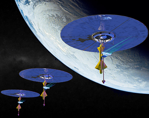


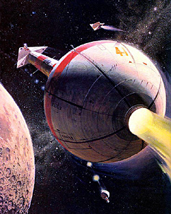
 This is mostly from Aviation Projects Review volume 1 number 3 which has more details than given here. Additional material from Helios pulsed nuclear propulsion concept (1965) which discusses the Lawrence Radiation Laboratory (LRL) Helios.
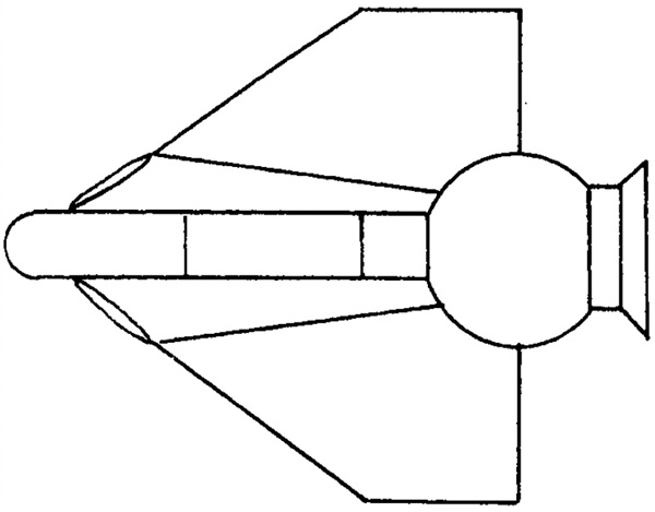
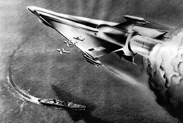


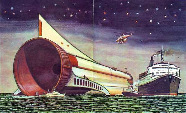


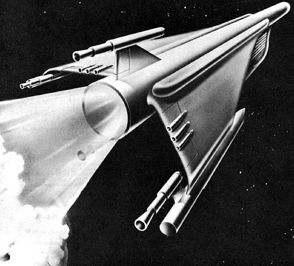


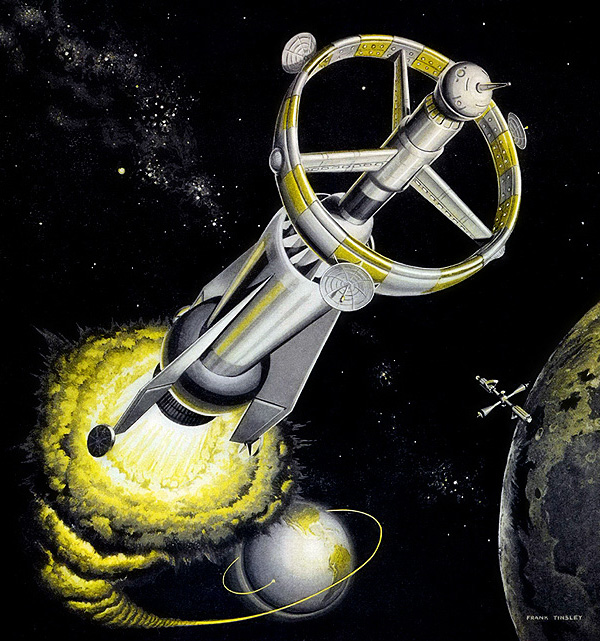

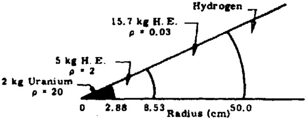
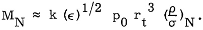
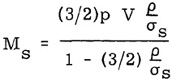
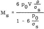
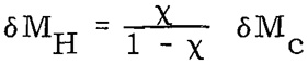
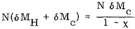
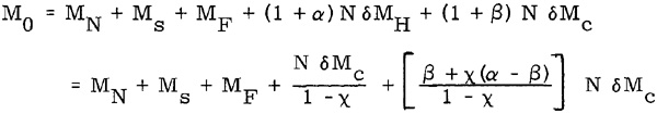
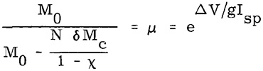


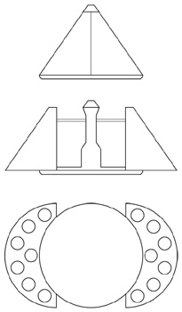
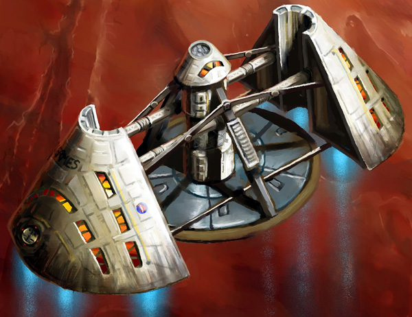


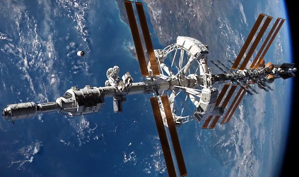
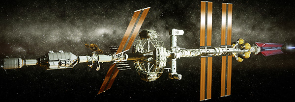
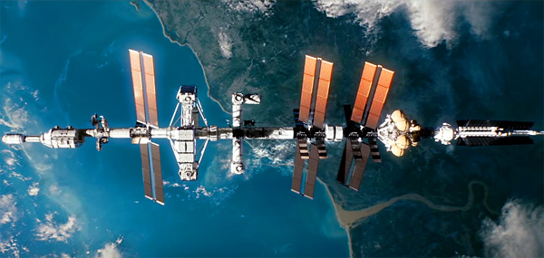
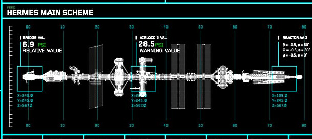
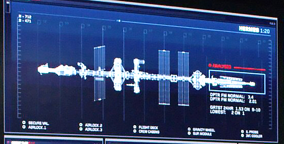
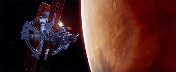
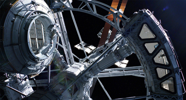
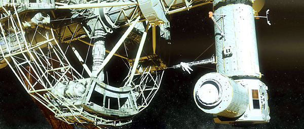
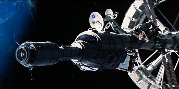
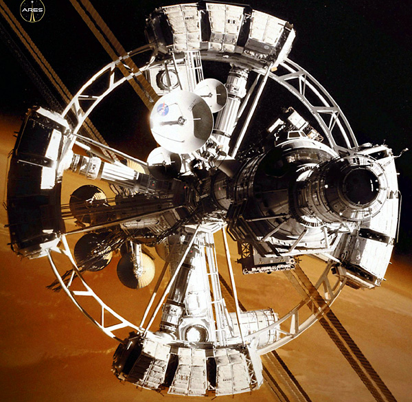
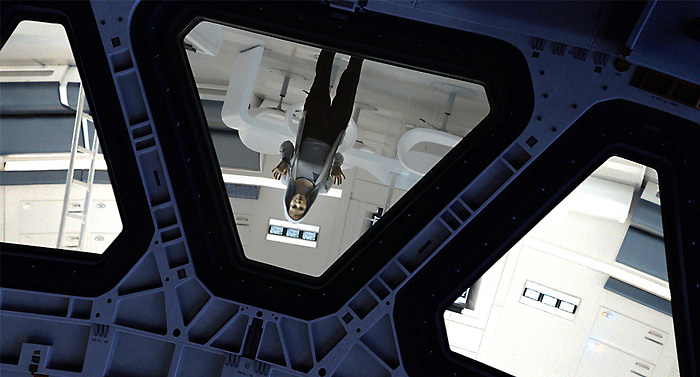


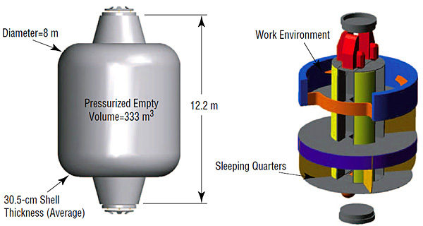


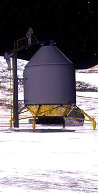
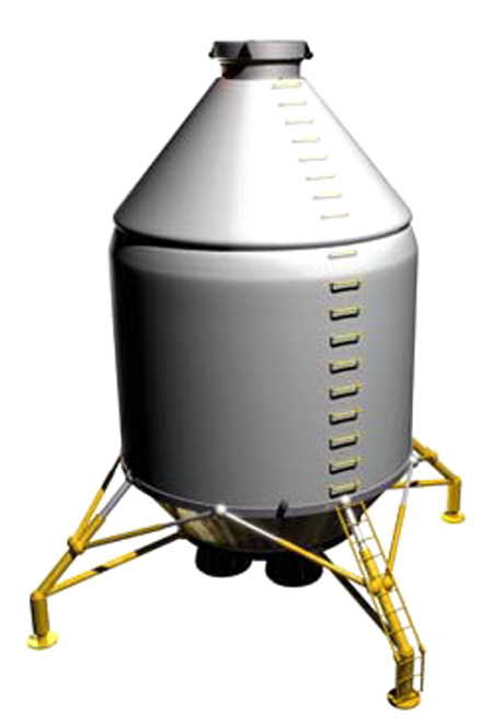

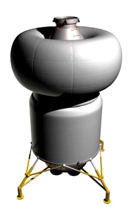
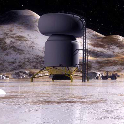
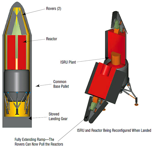
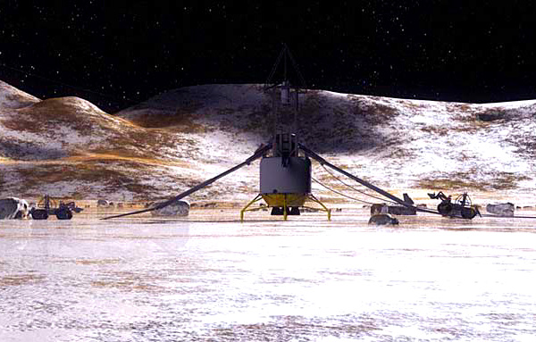
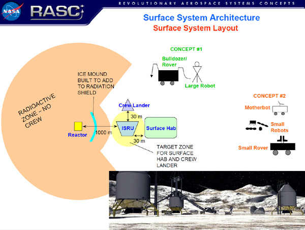


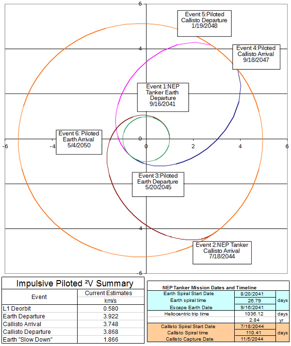
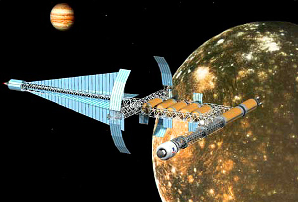


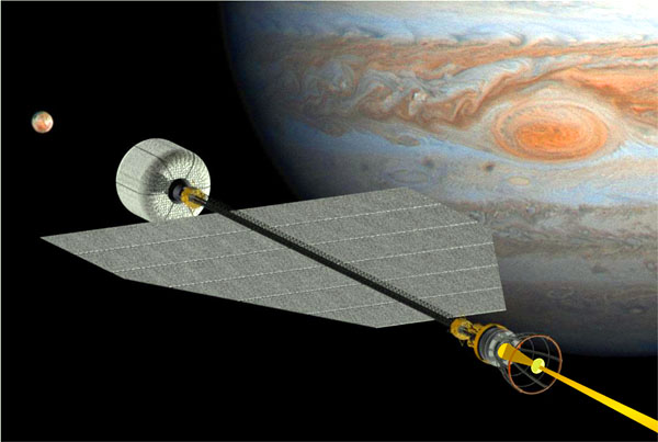
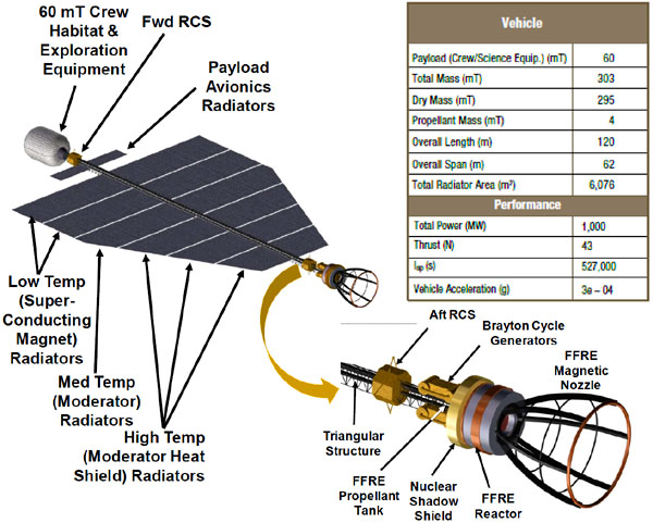
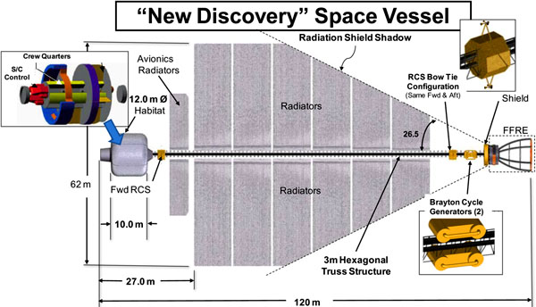
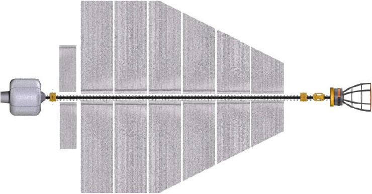
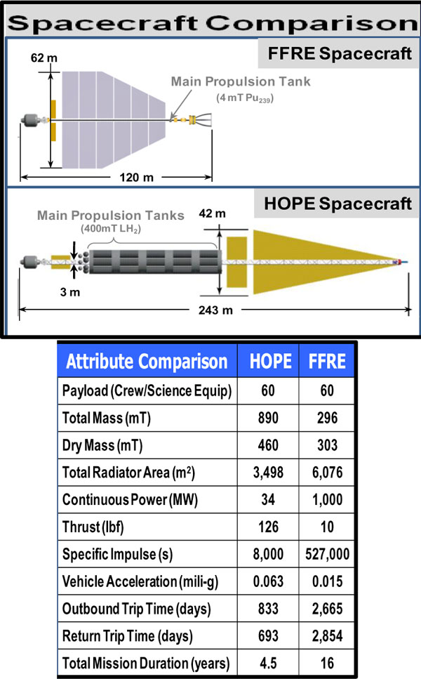
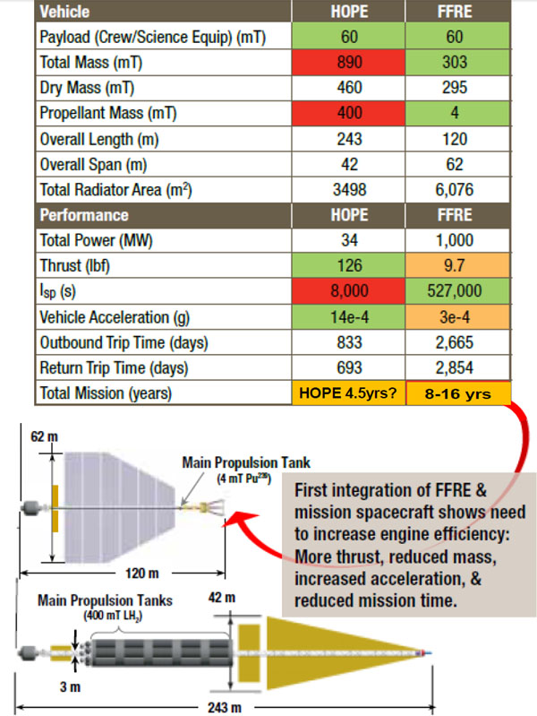


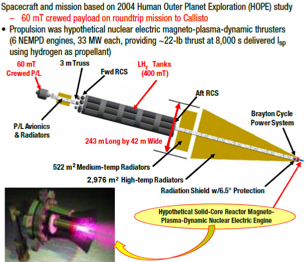
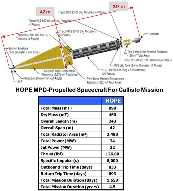


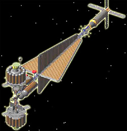
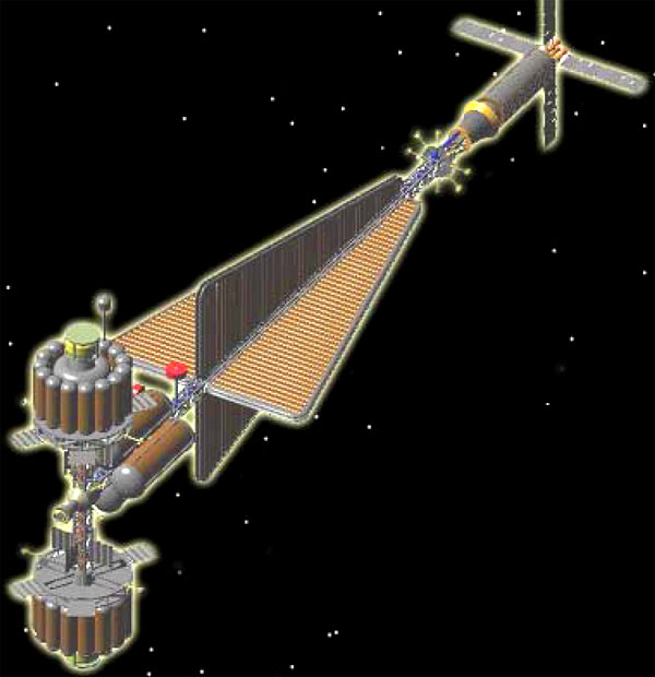
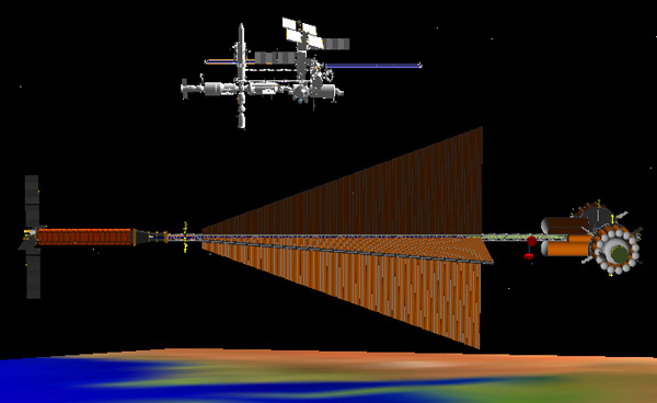


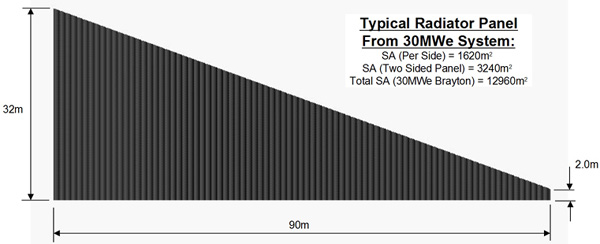
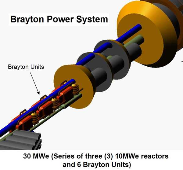


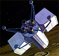
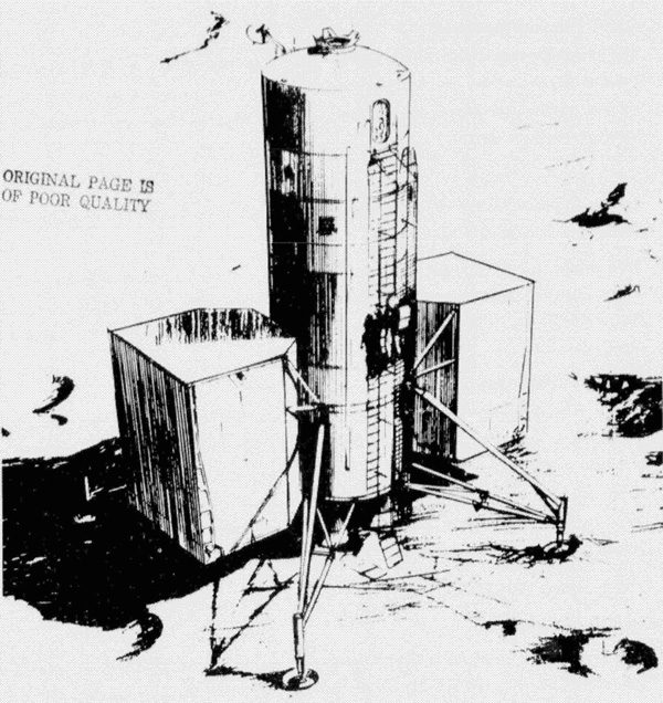

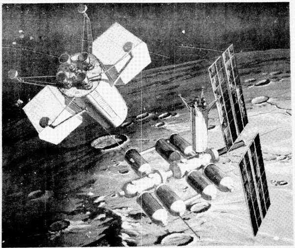


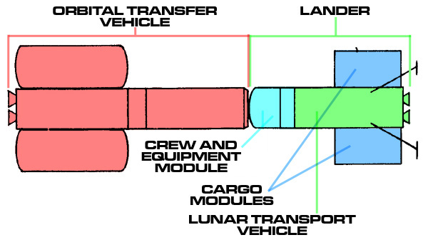
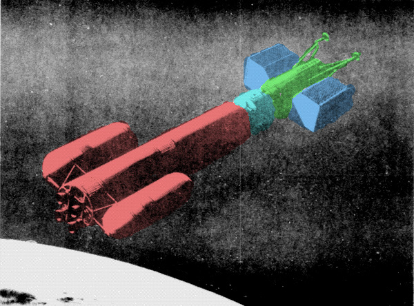
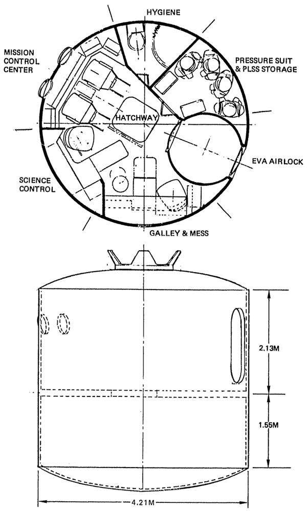
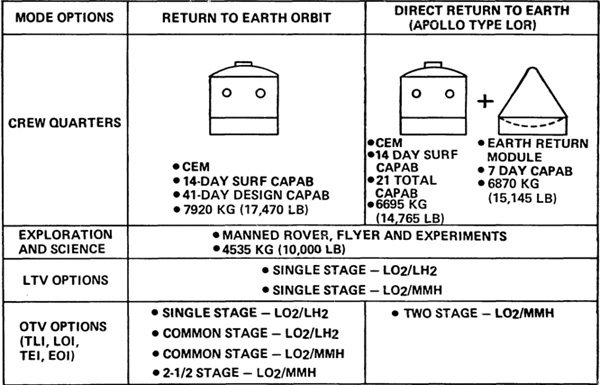
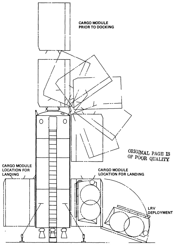


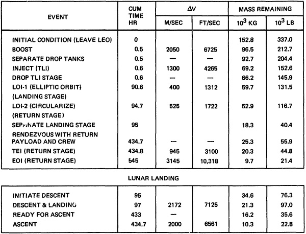


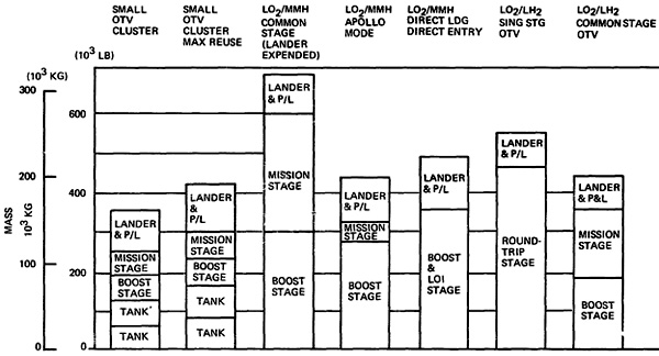


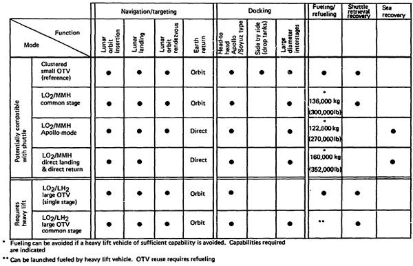
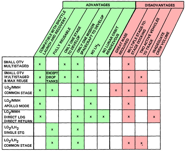


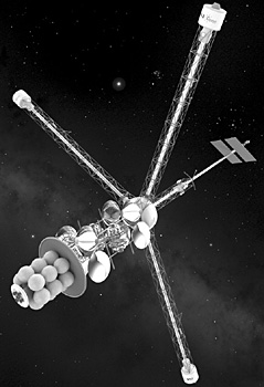
 The spacecraft is named after Konstantin Tsiolkovsky. Who you better have heard of or RocketCat is going to give you such an atomic wedgie.
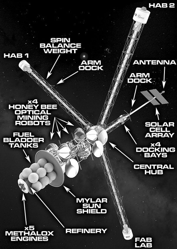


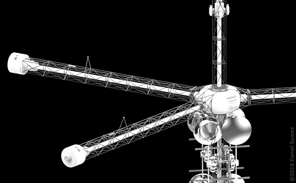
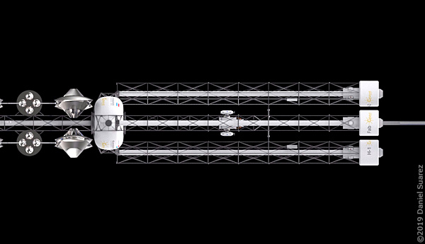
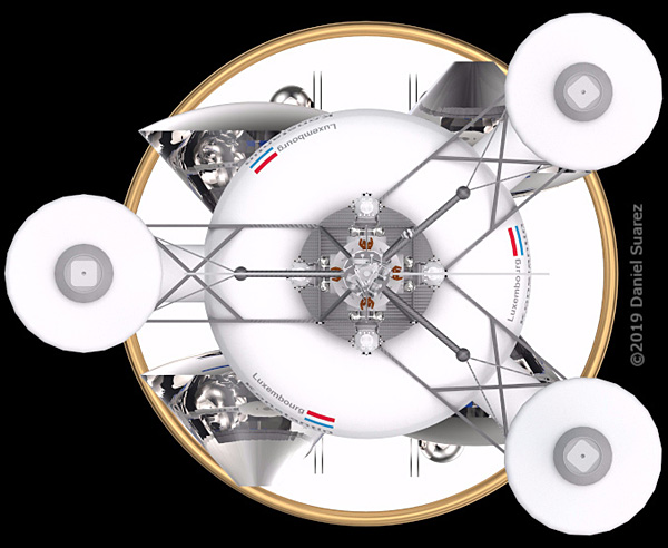
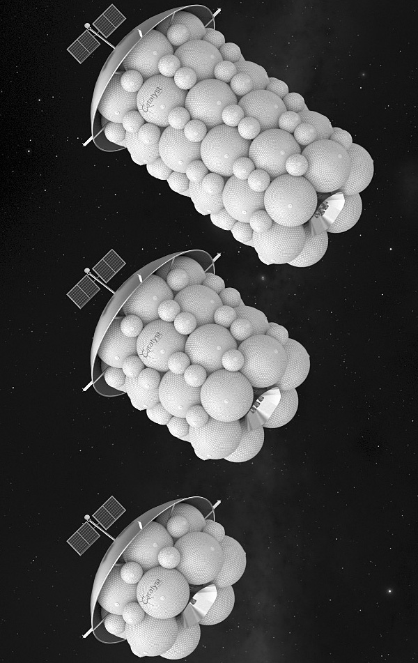
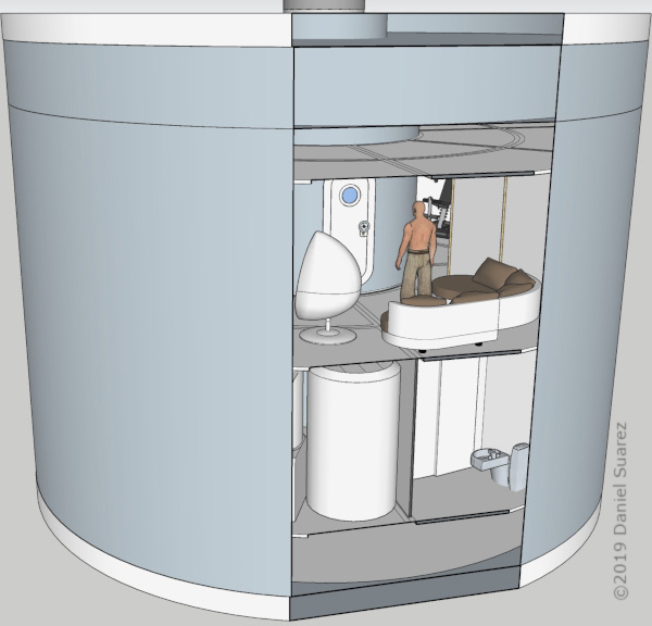
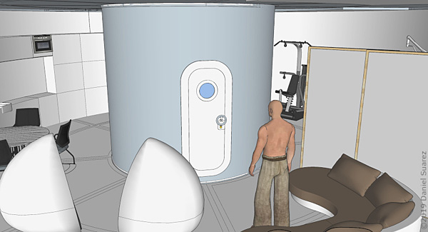
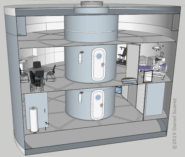
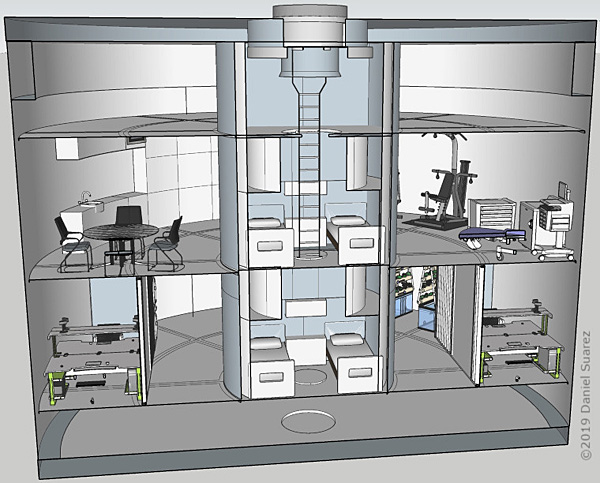
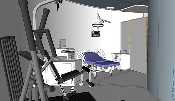
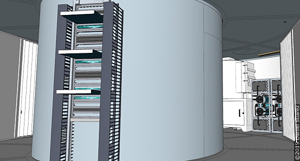
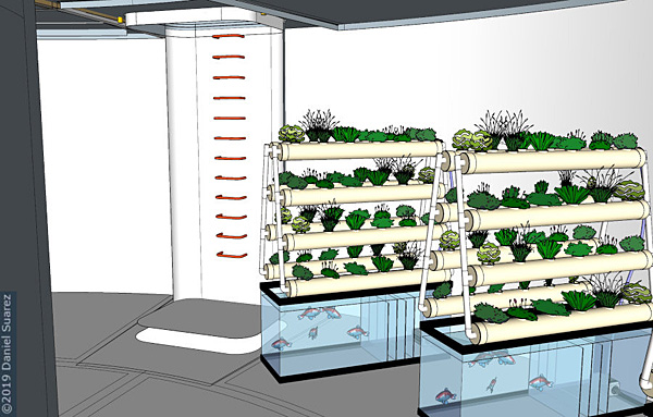
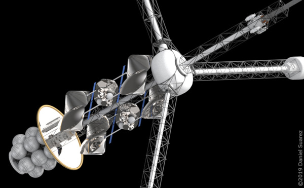
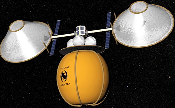

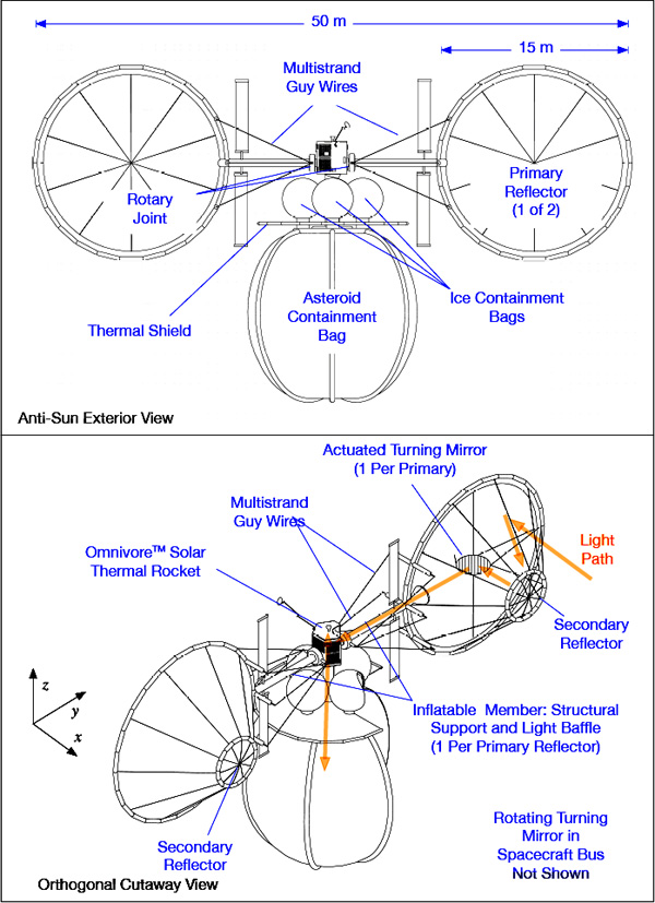
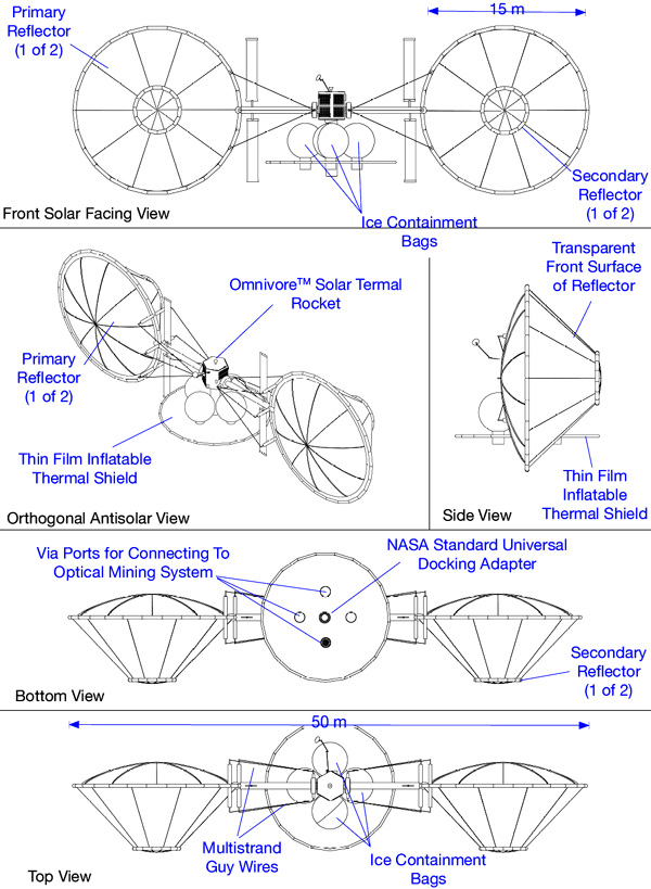
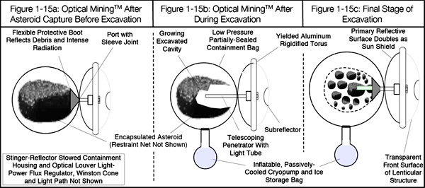
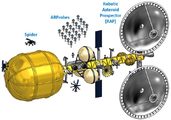

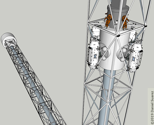
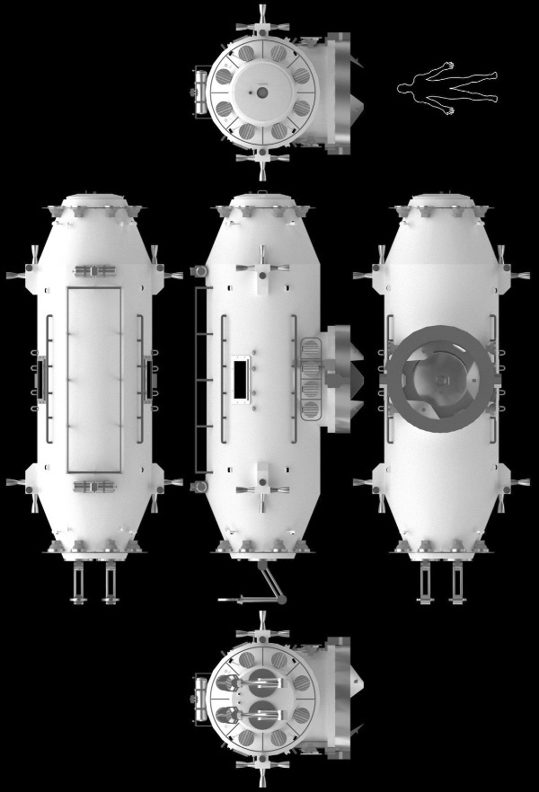

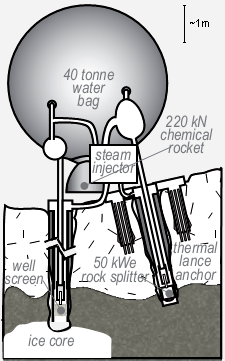
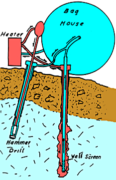


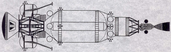
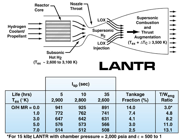


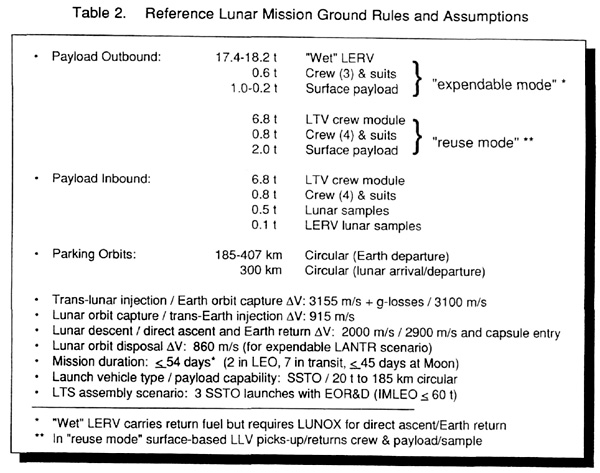
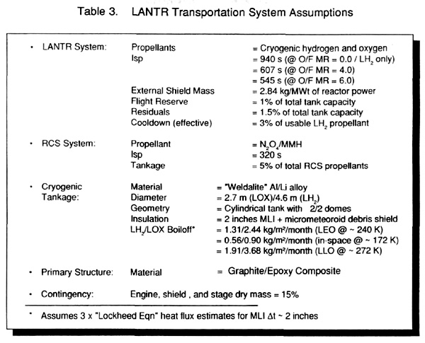
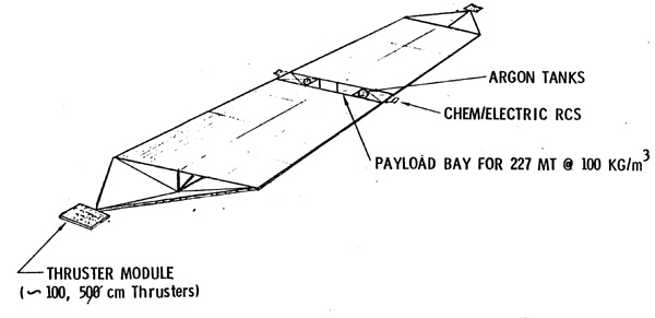
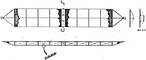
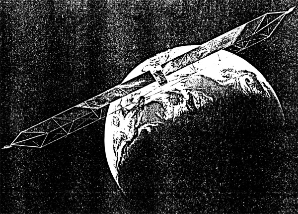
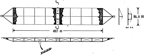
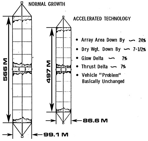
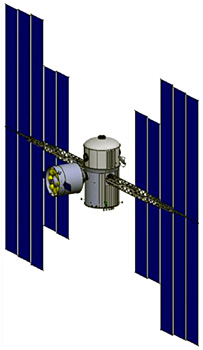
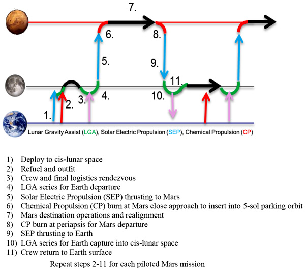
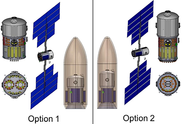
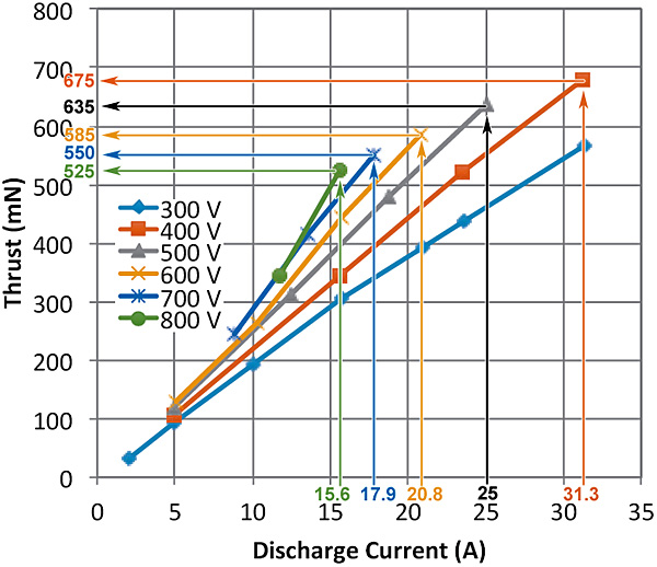
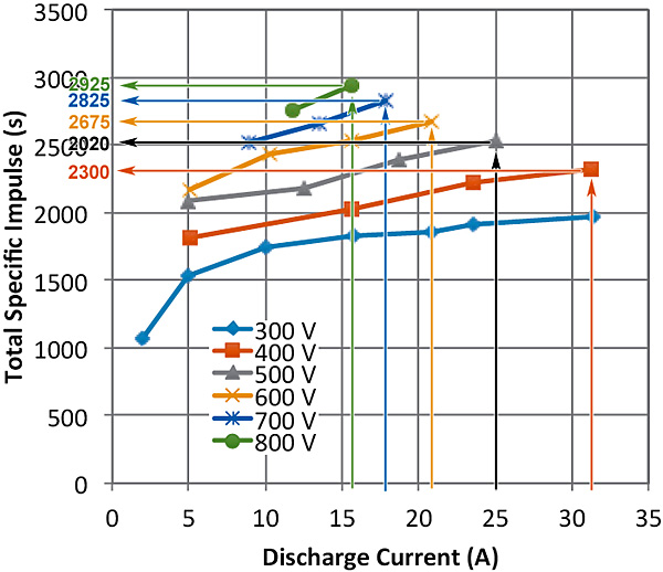
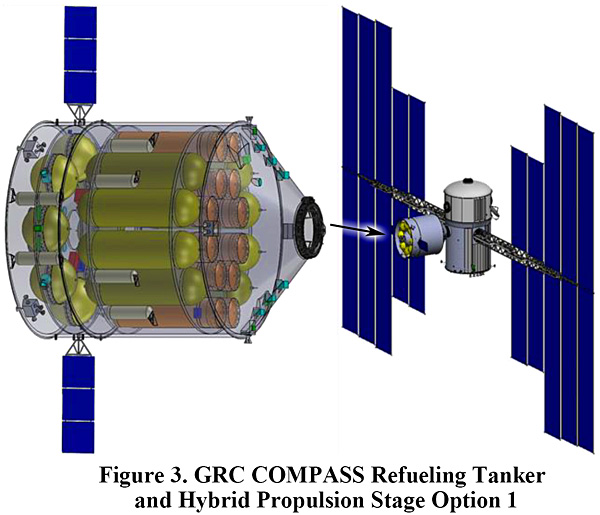


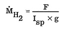
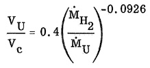
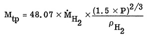
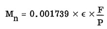
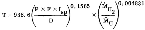
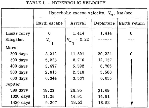
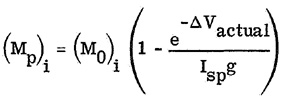
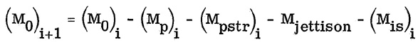
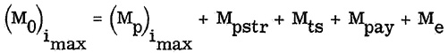
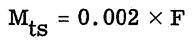

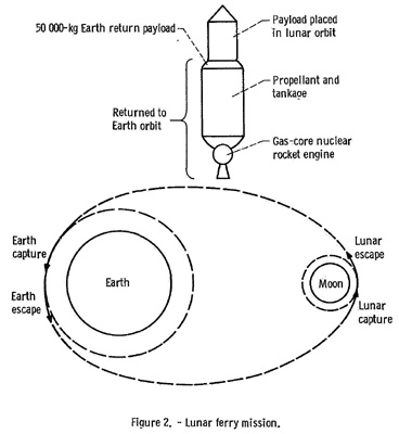


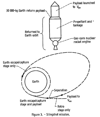


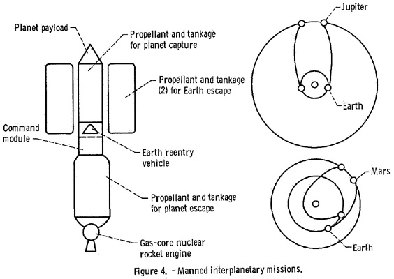


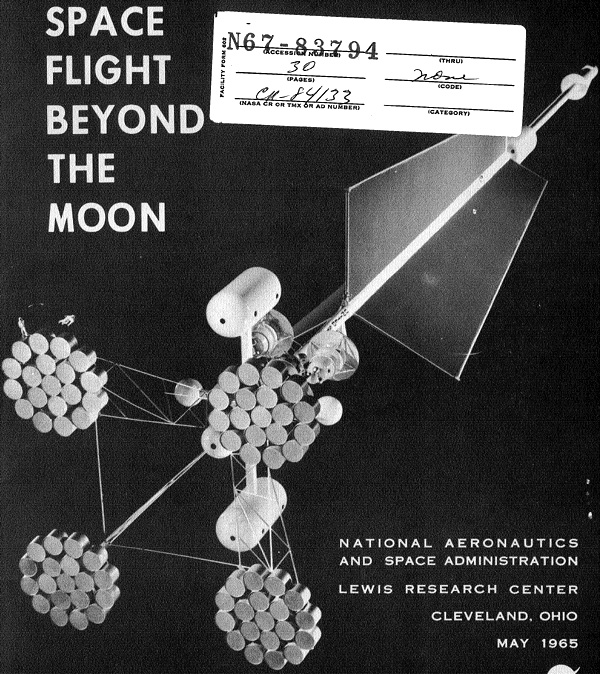
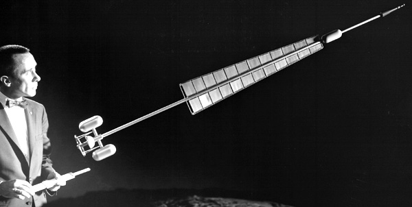
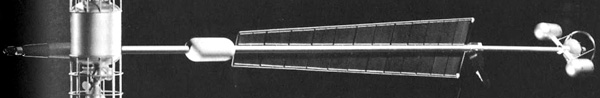
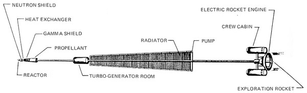
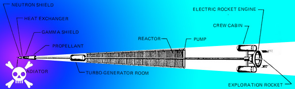
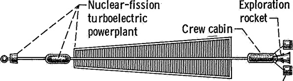
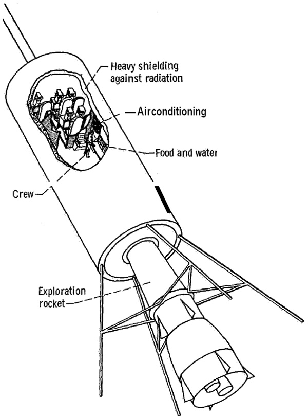
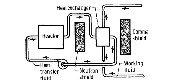
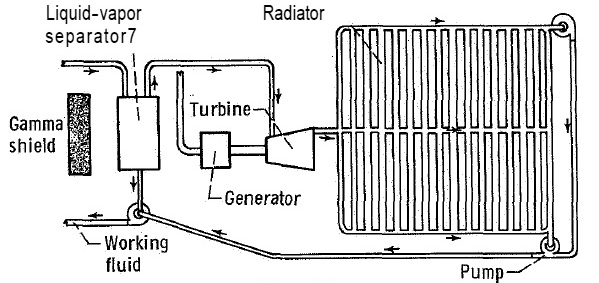
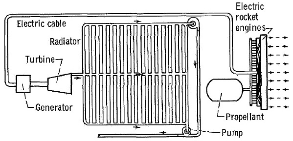
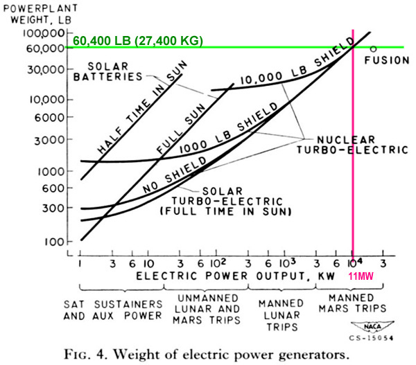
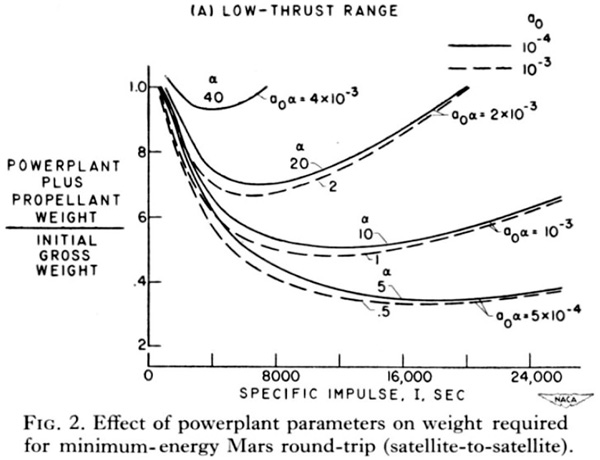
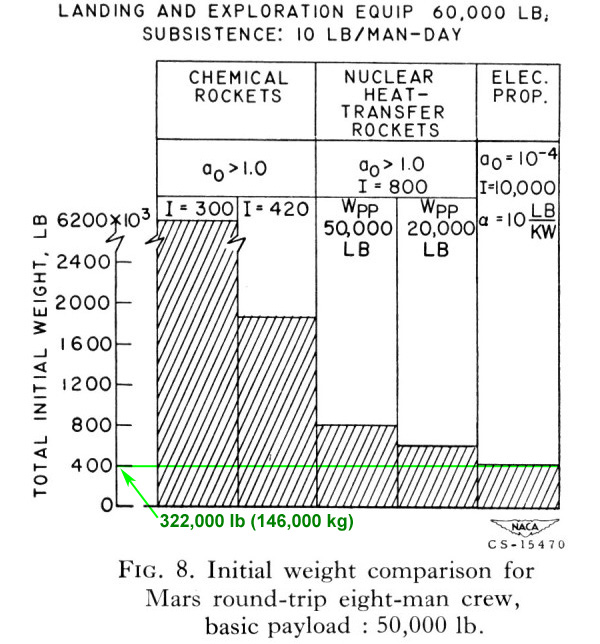
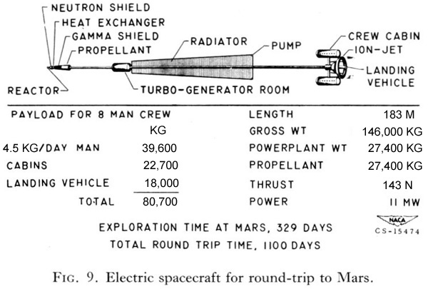
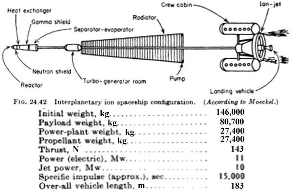

 Lewis Ion Ship Concept


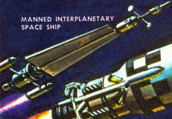


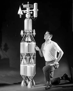


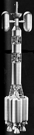

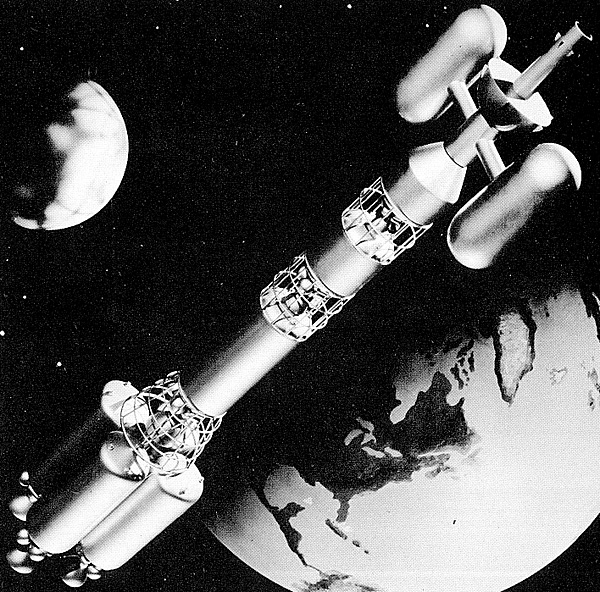
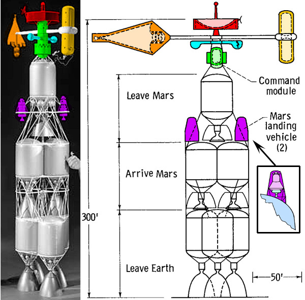
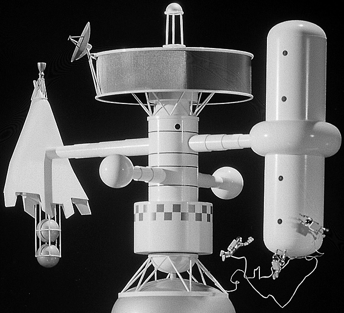
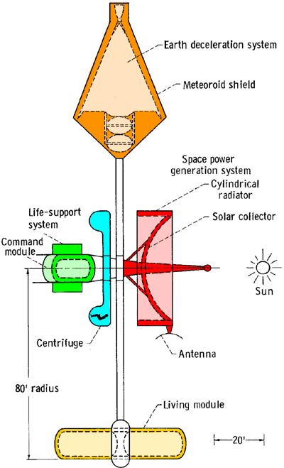

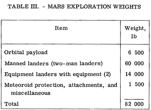
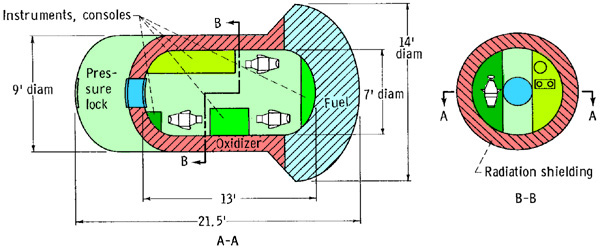
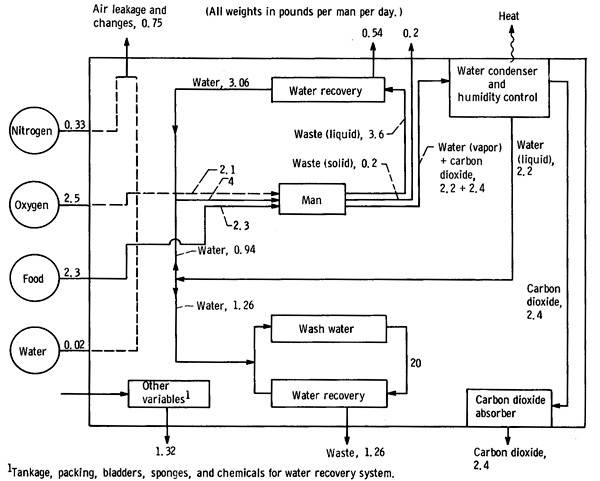
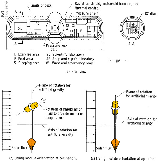
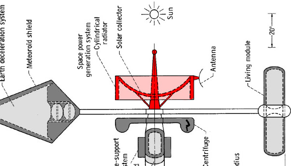
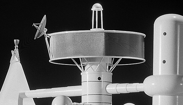
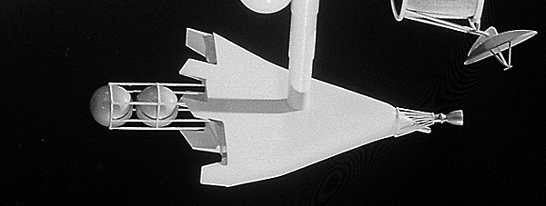
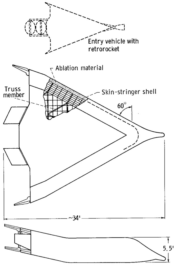
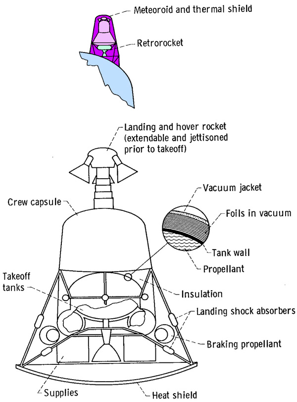
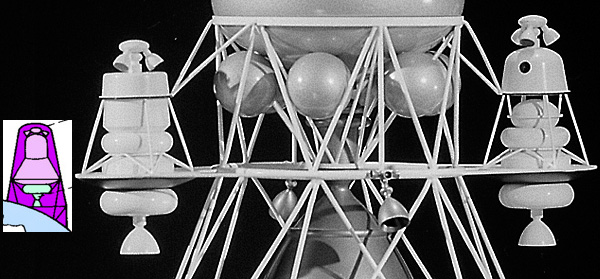
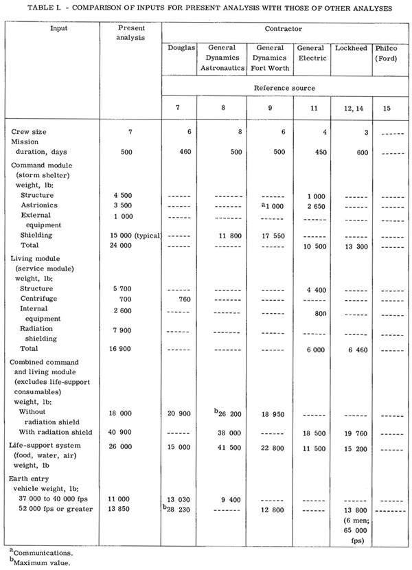

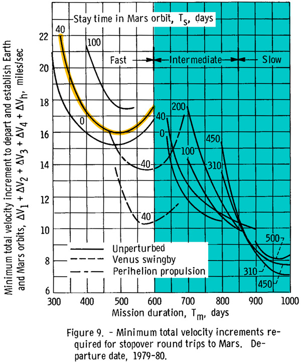
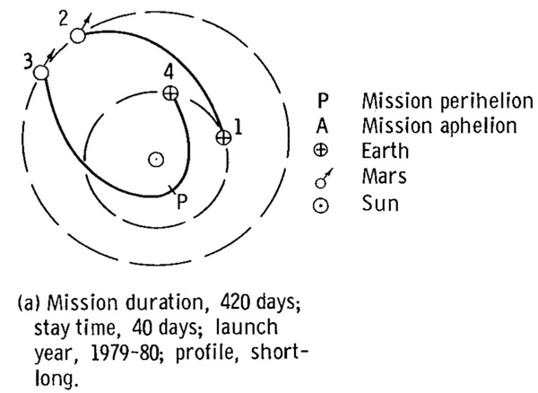
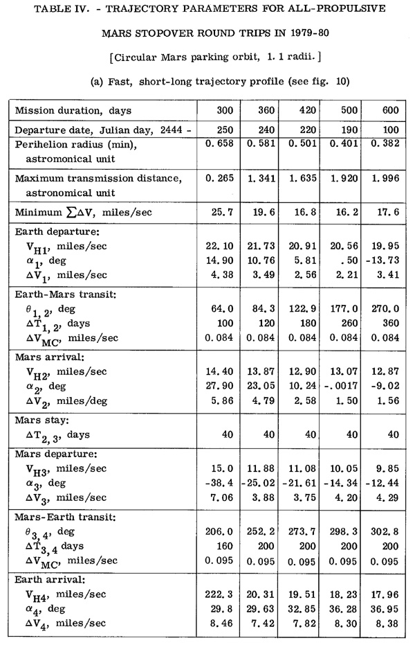
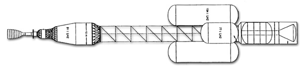
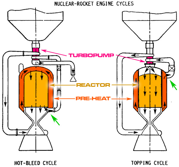


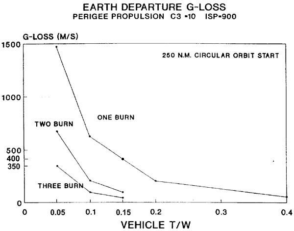


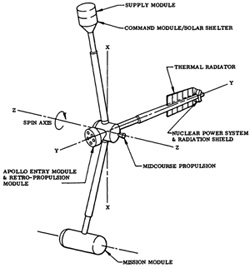


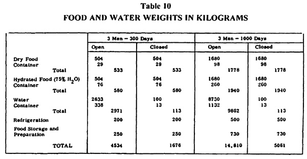
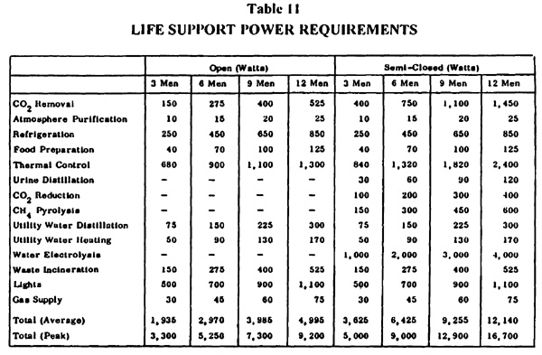
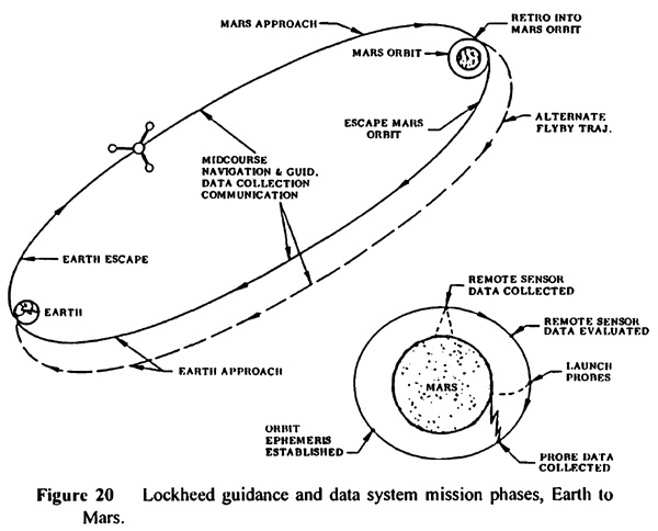
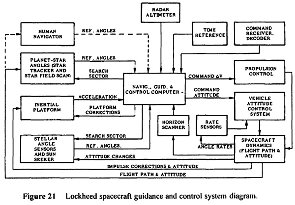

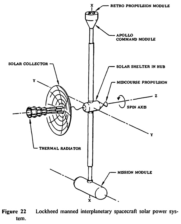

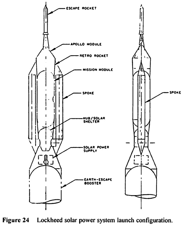
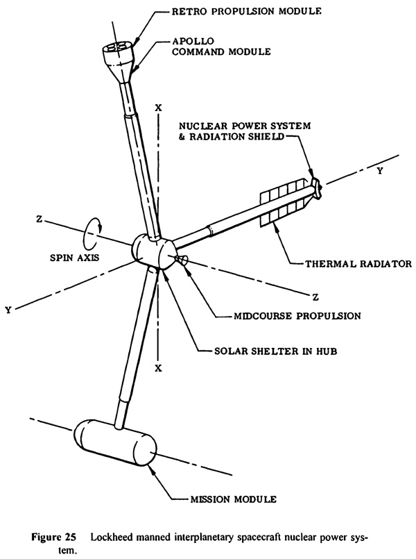
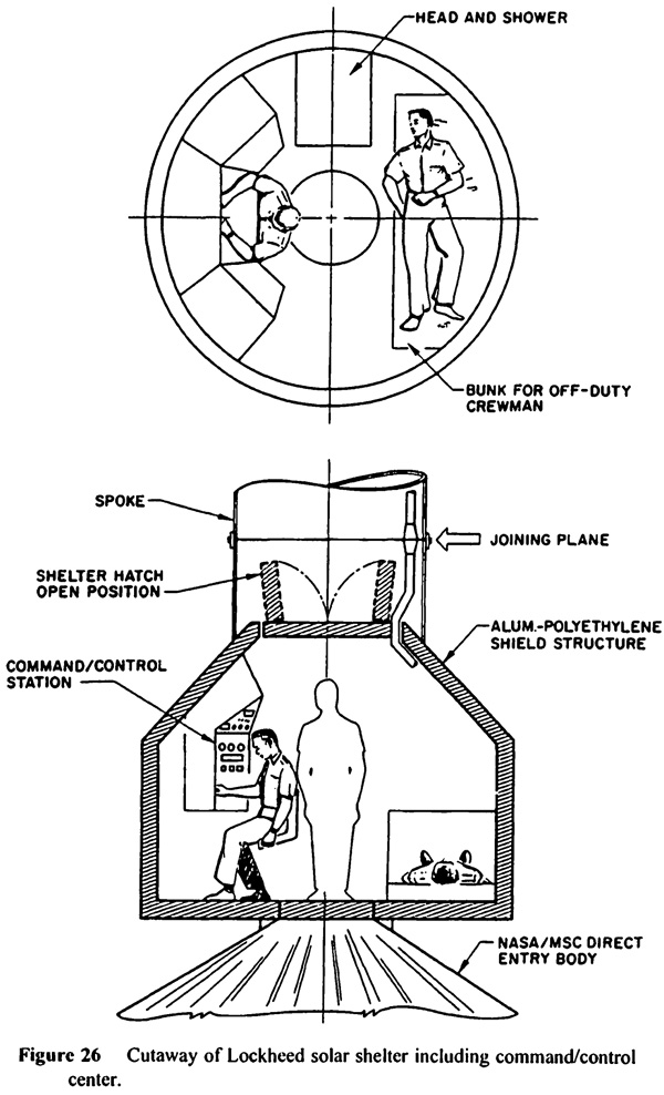
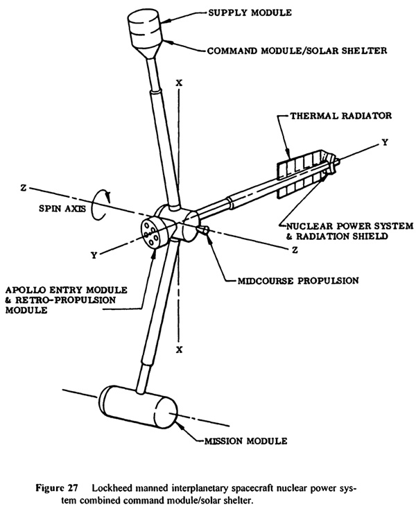


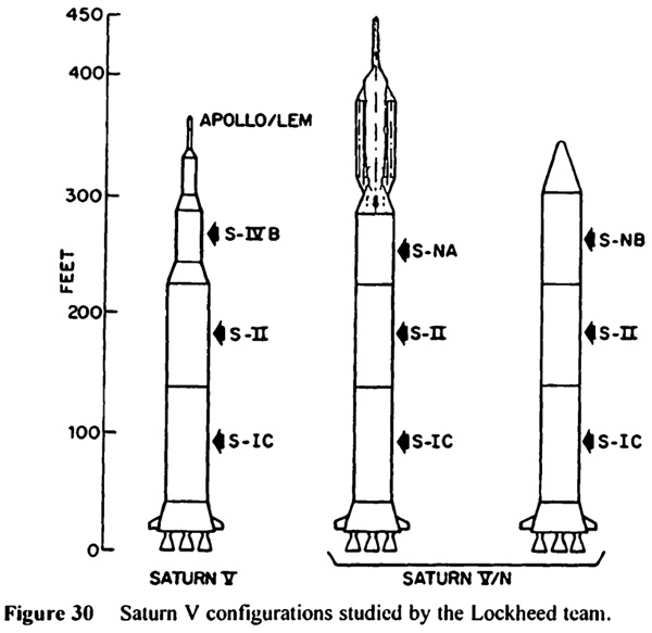
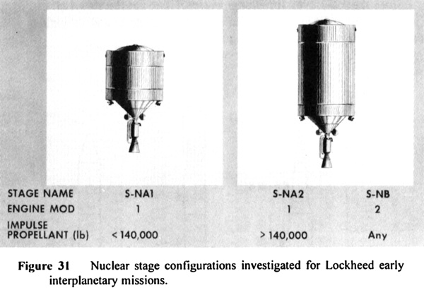
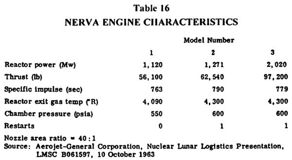
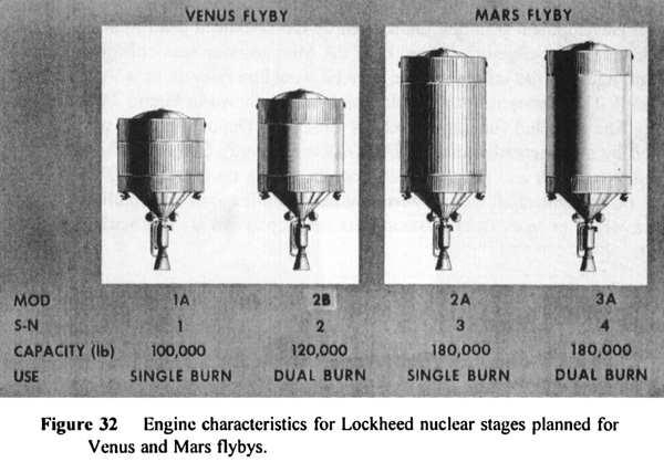
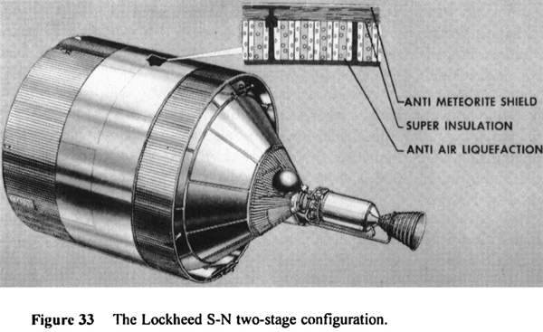
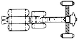

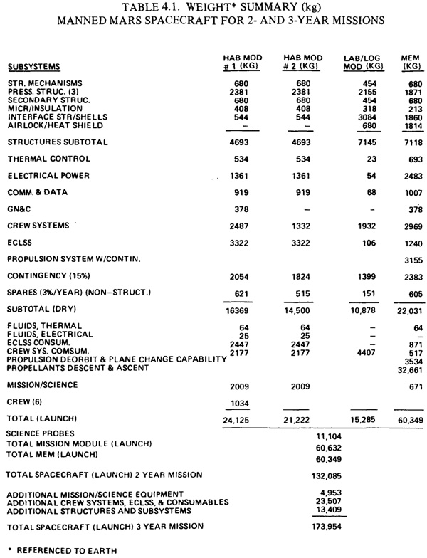
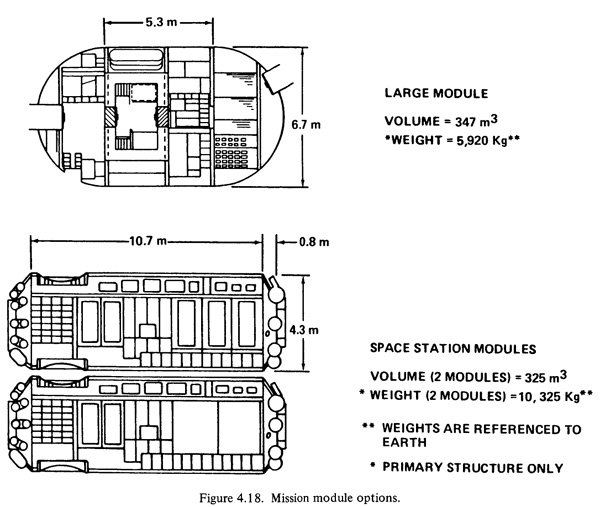
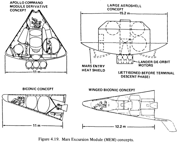


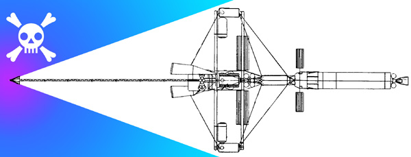


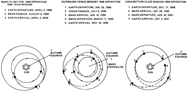
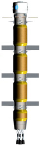
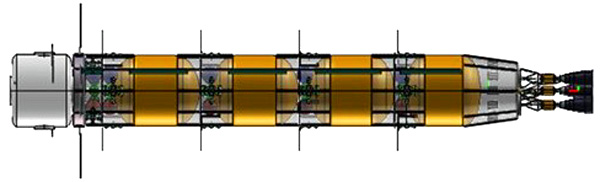
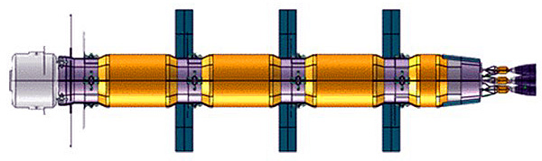
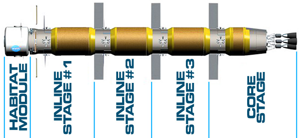
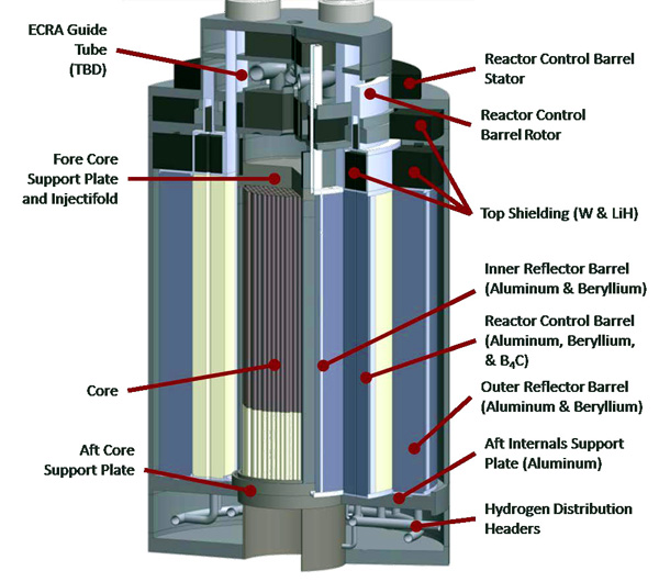
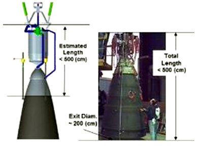


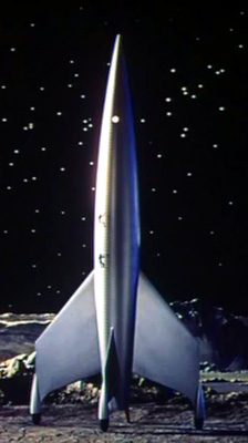
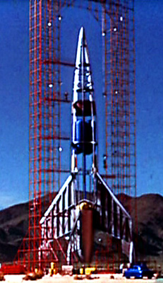

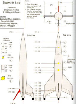
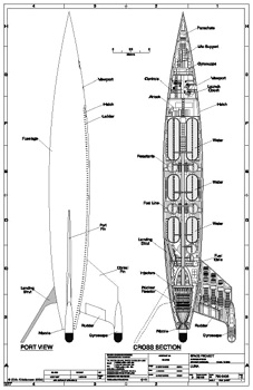
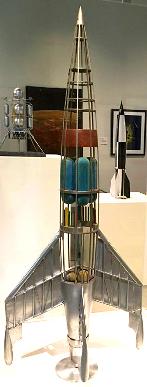
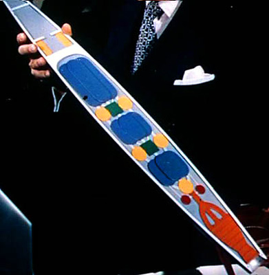
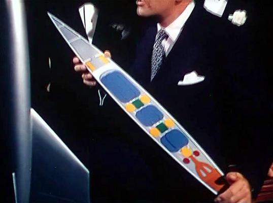
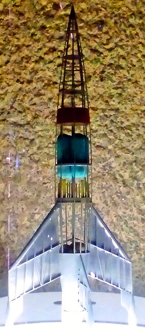


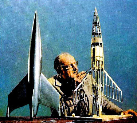
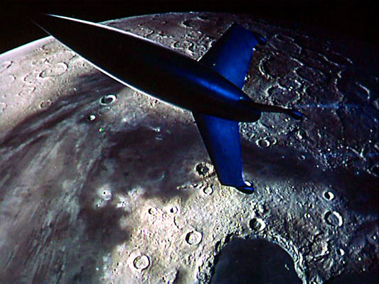


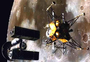
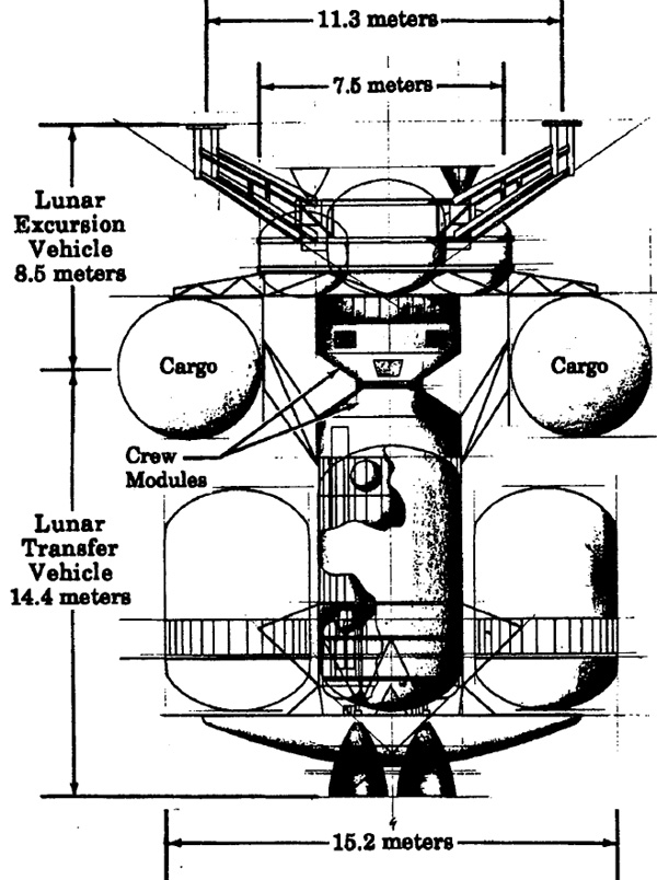
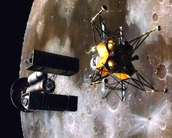
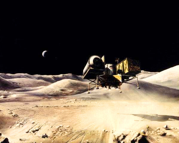
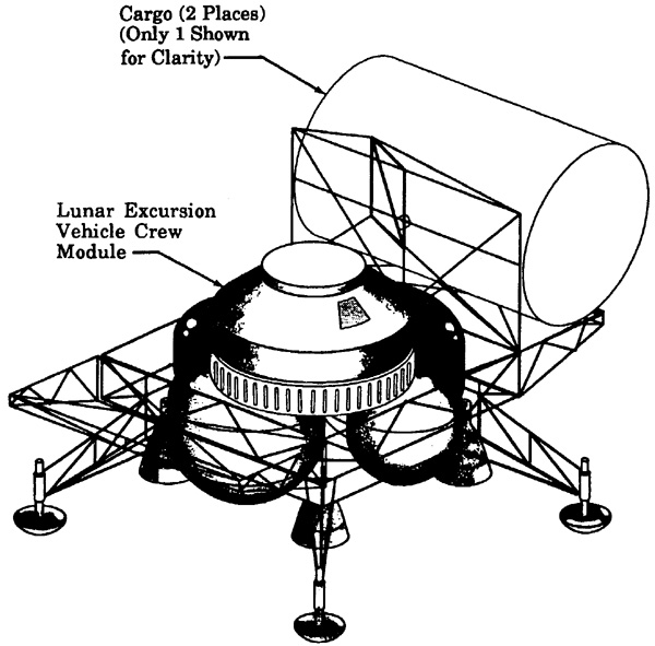
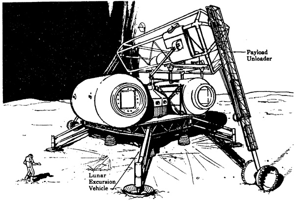
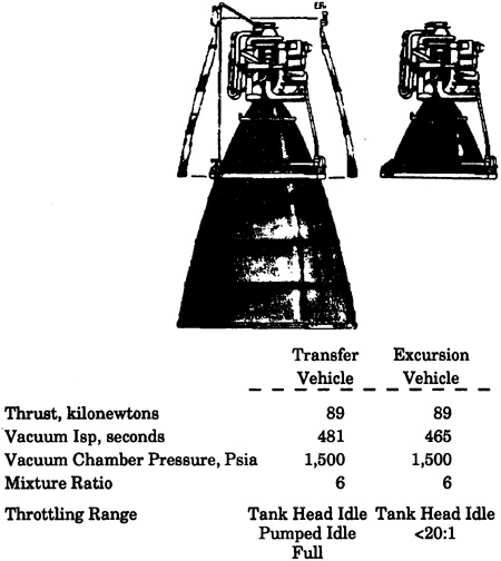
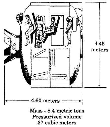
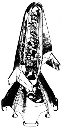


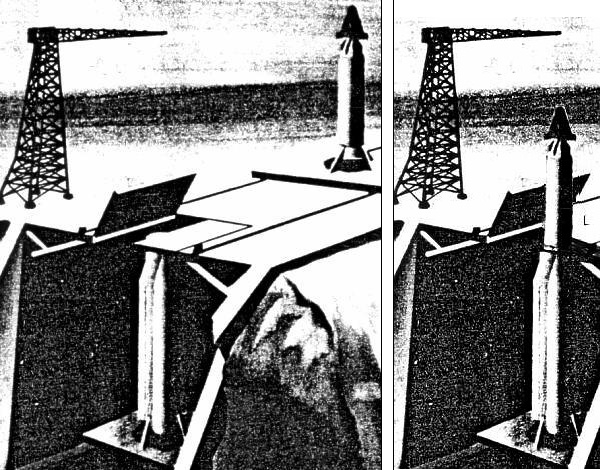
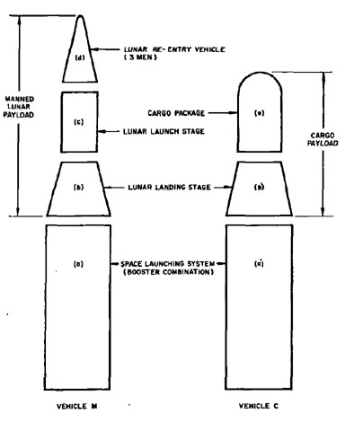


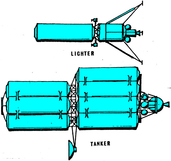
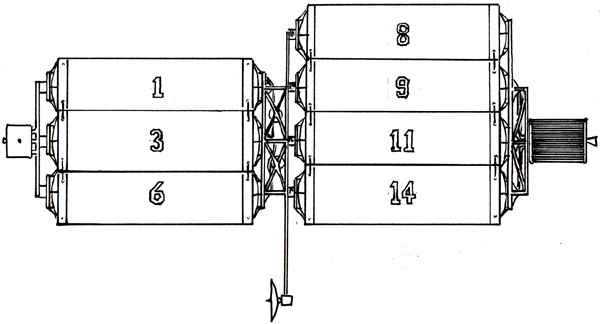
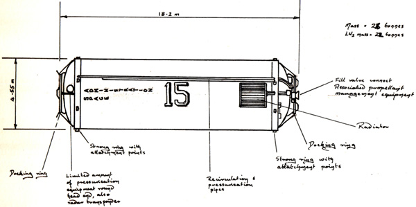
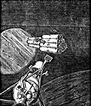
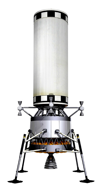
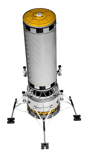


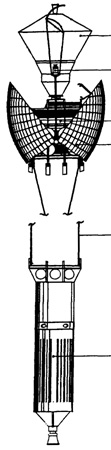
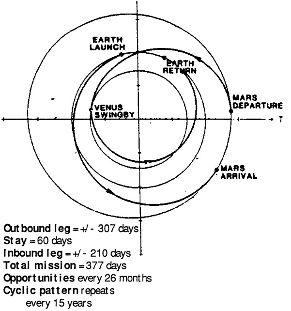


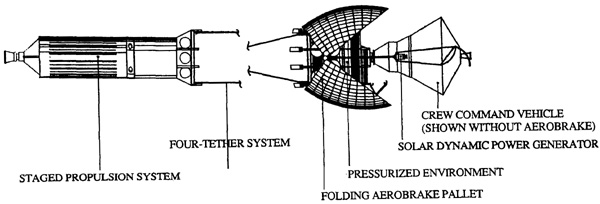
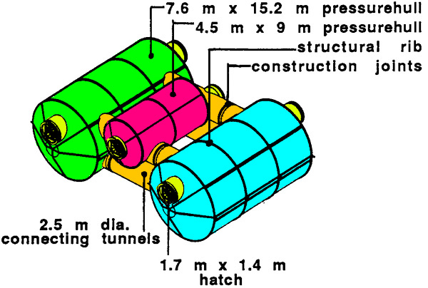
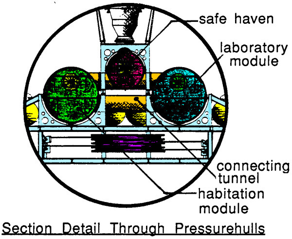
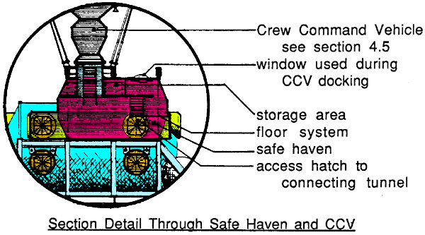
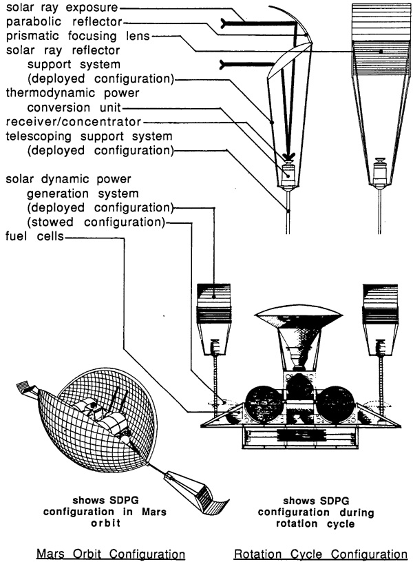
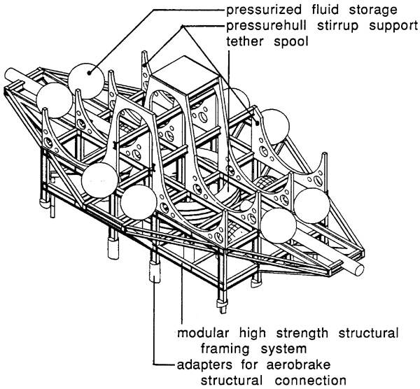

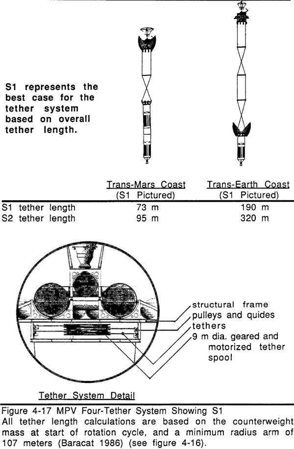


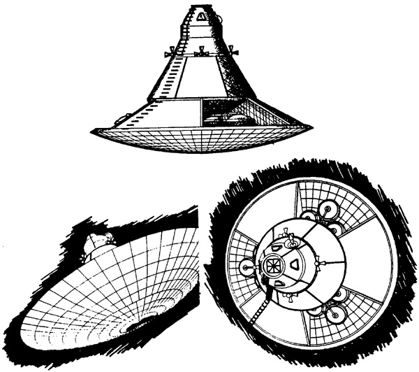
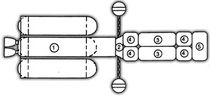
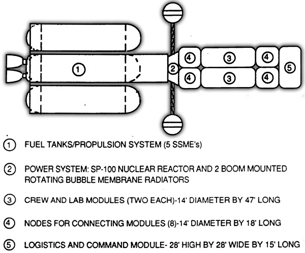
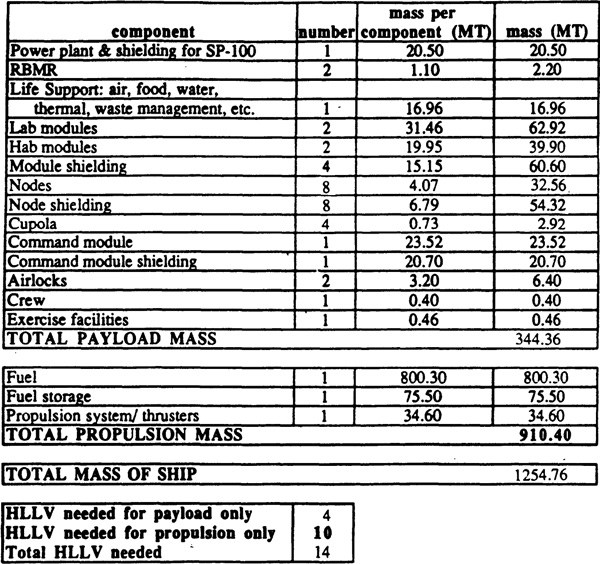
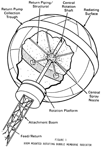


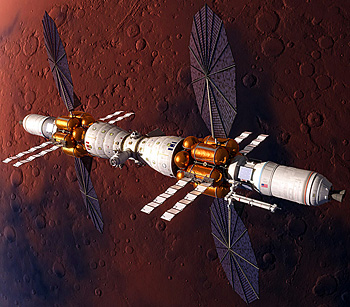


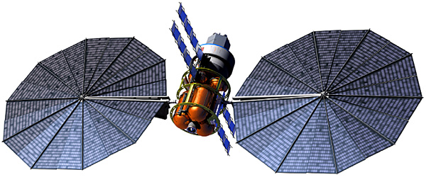


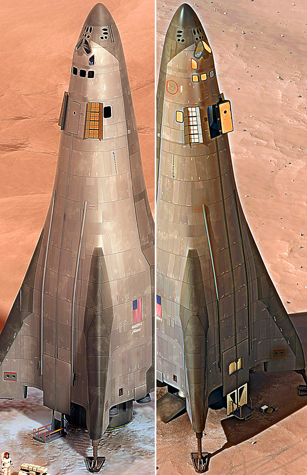


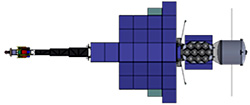

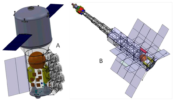
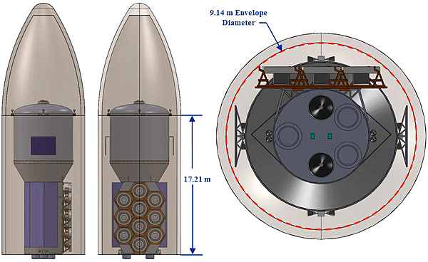
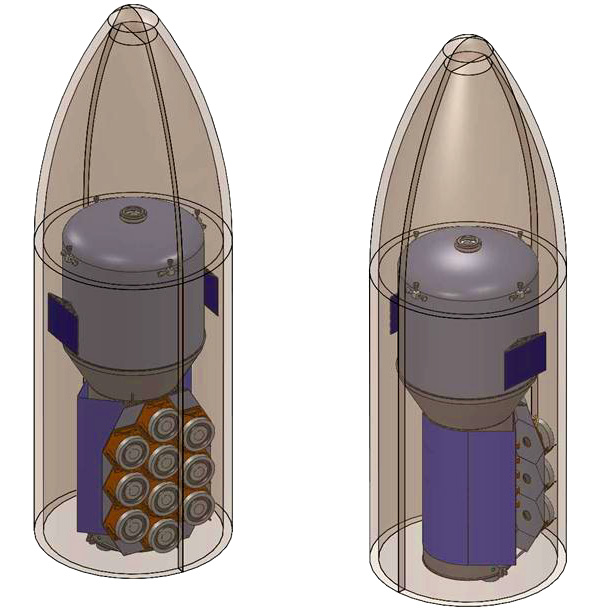

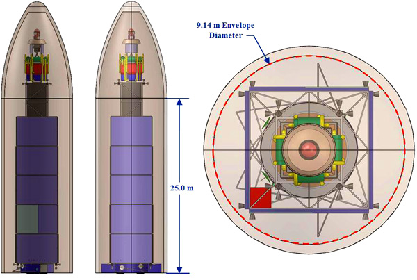
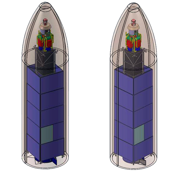
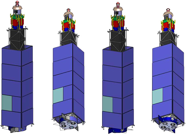
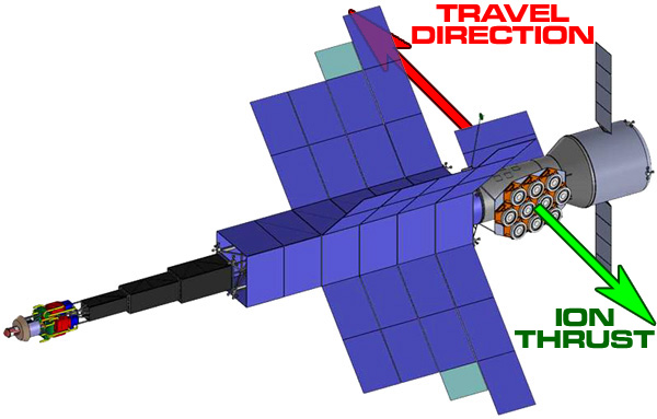
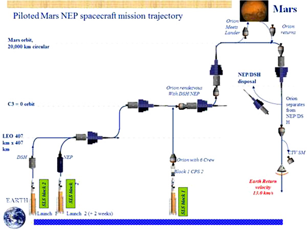


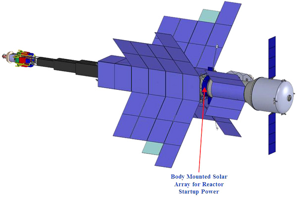
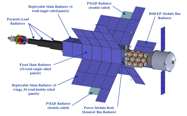
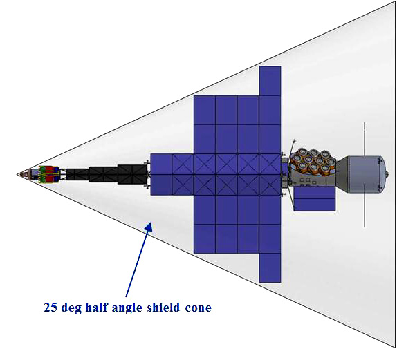
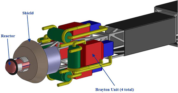
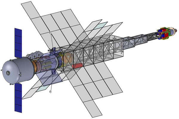
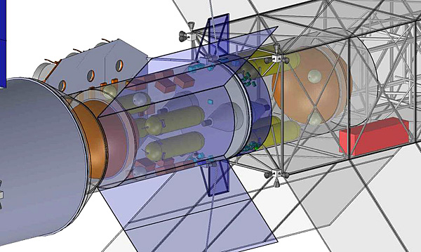
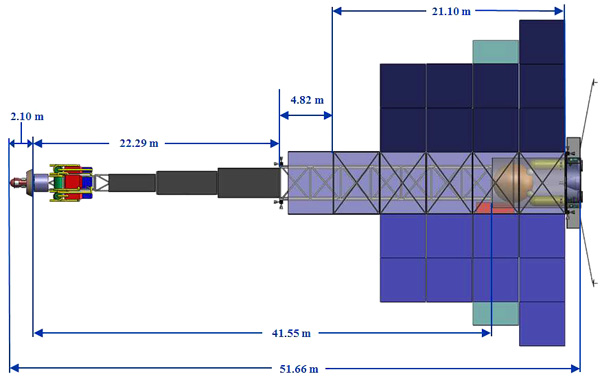
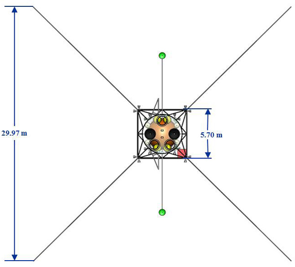
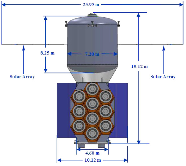
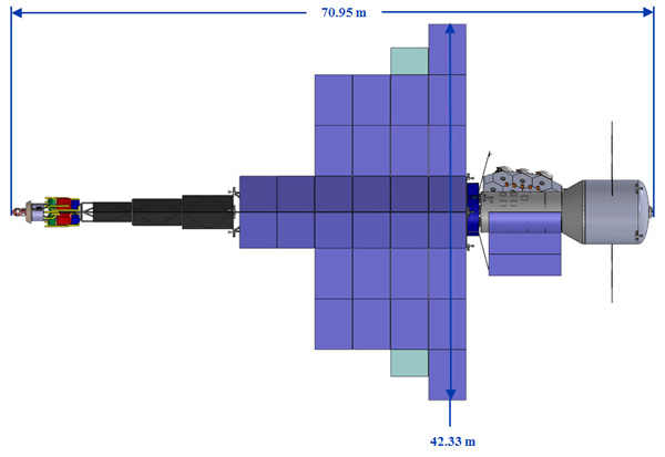
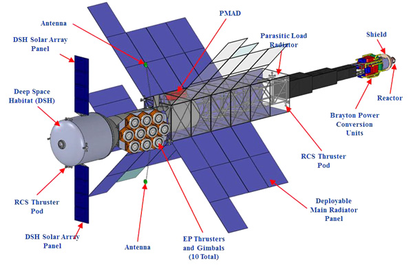
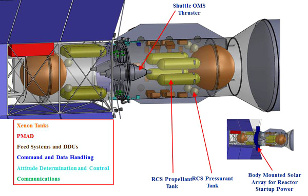
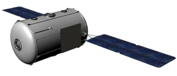

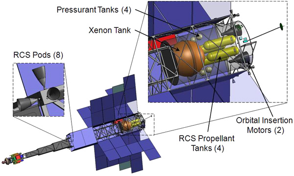
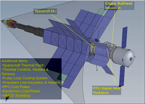


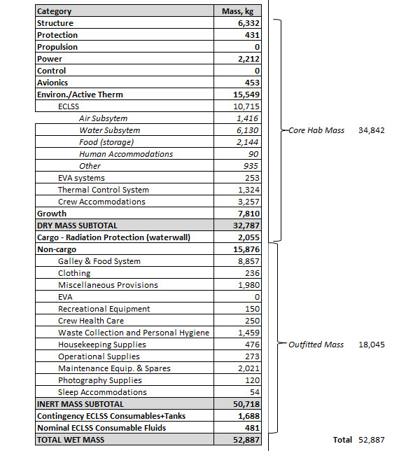


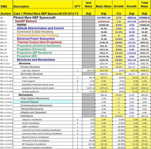
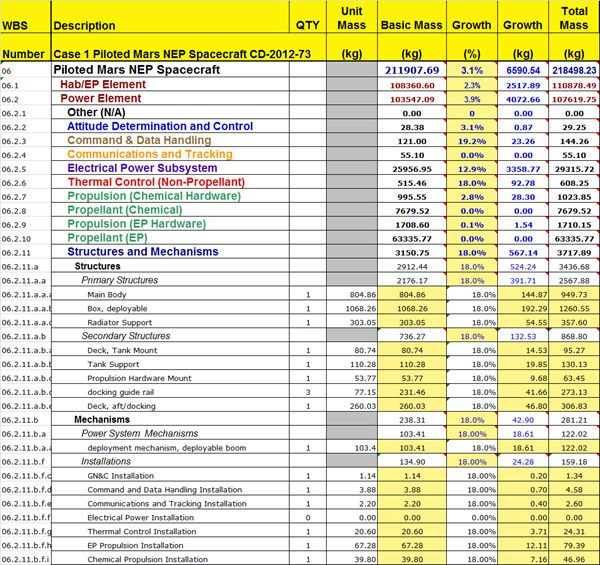


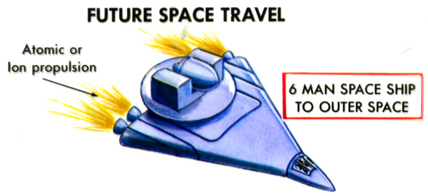
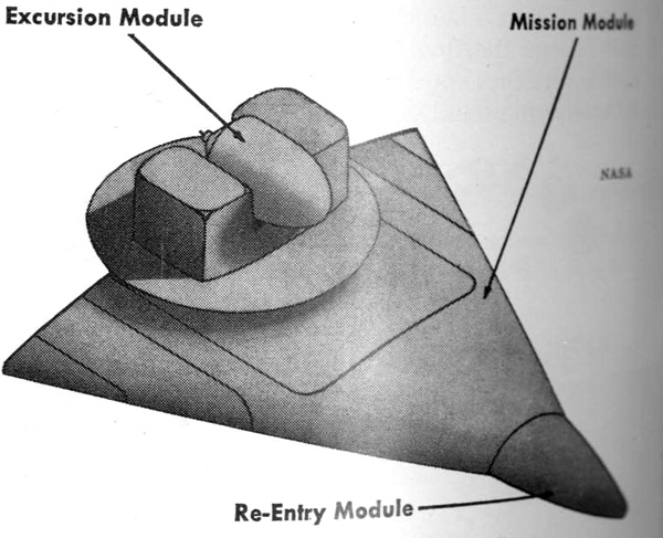


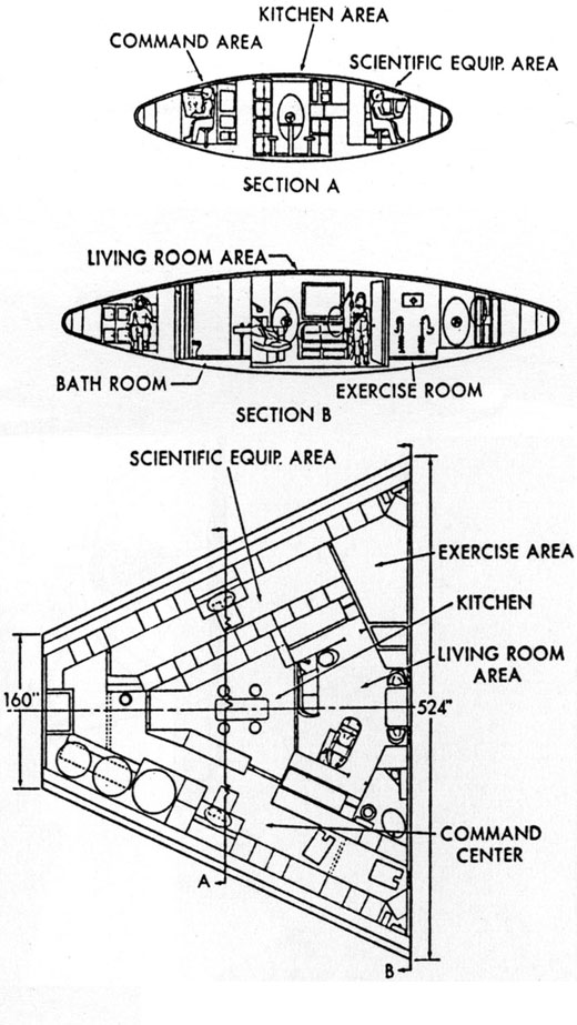
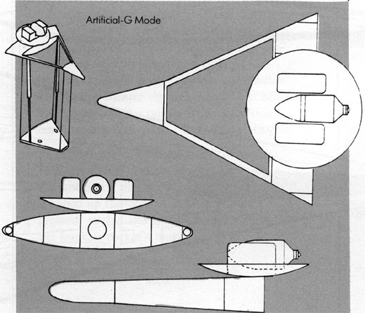
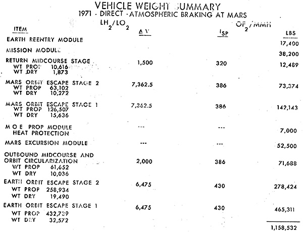
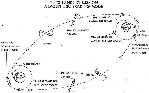
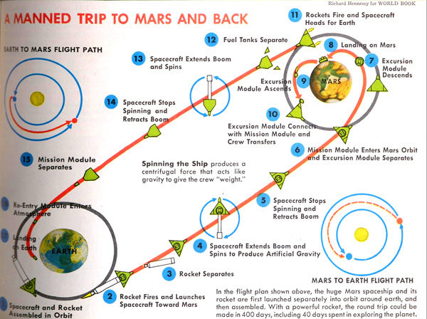
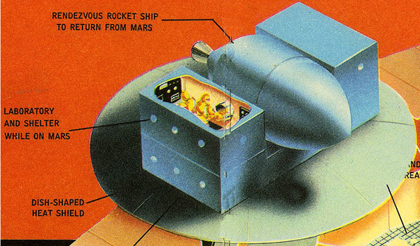

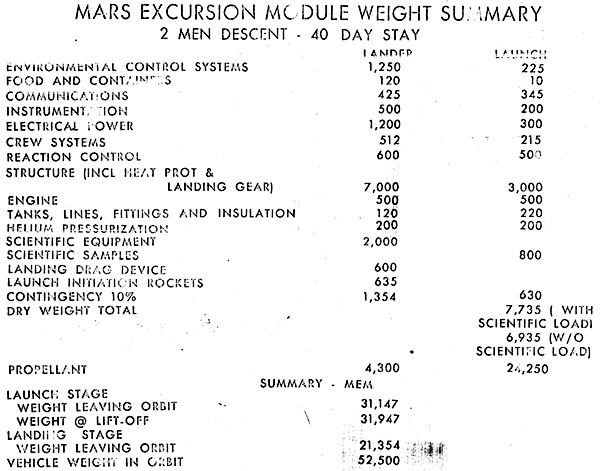


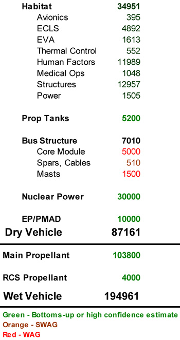
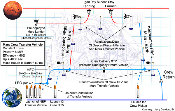


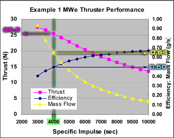


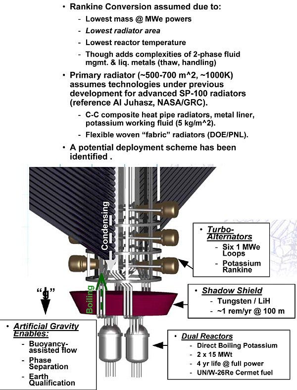
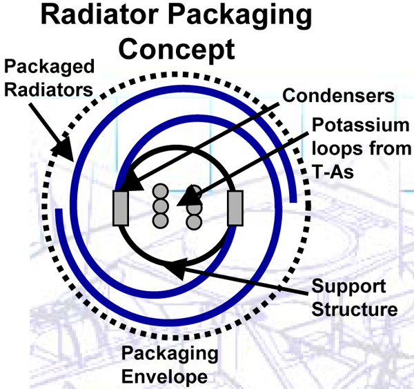
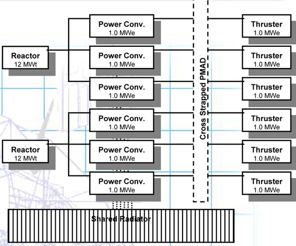

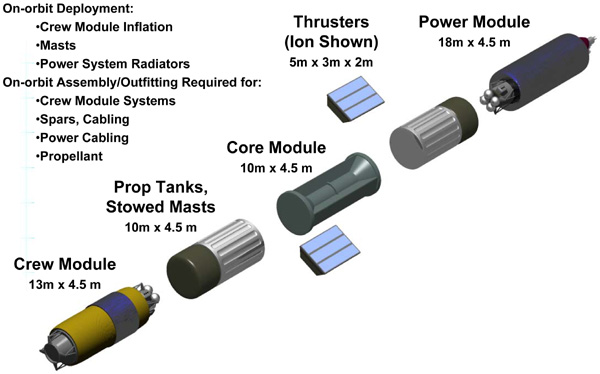


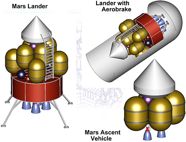


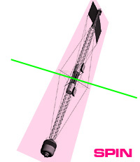

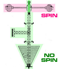
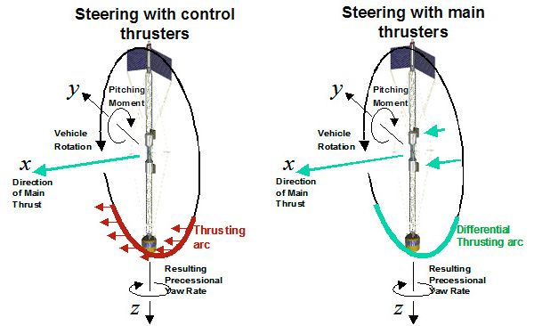
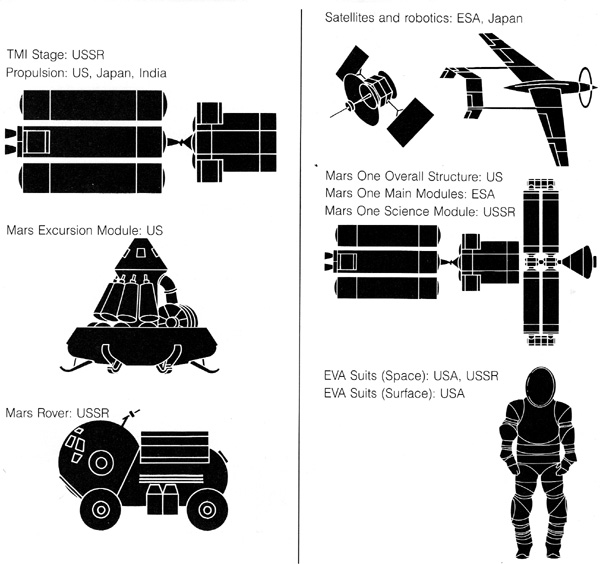


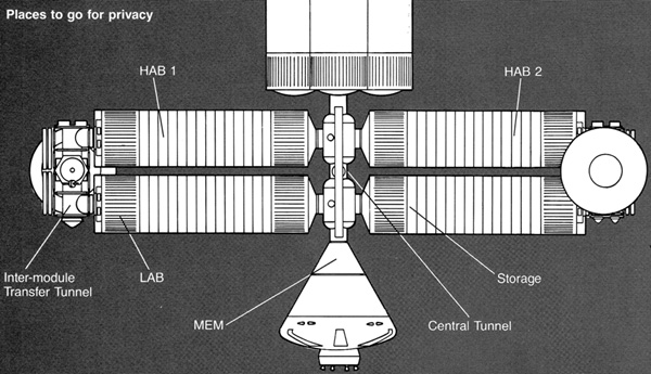


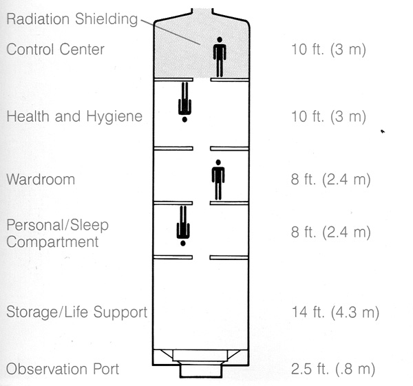
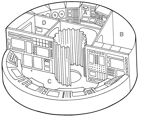
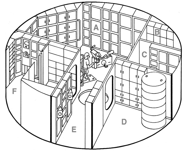
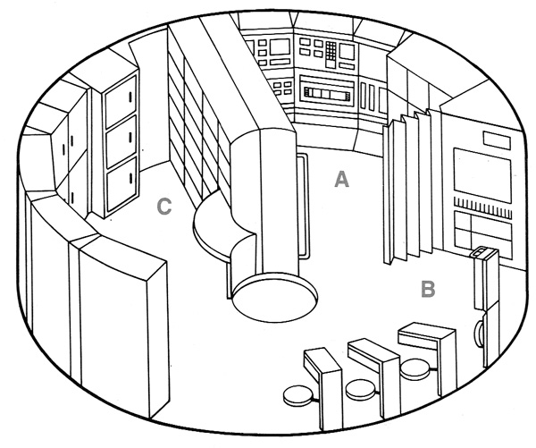
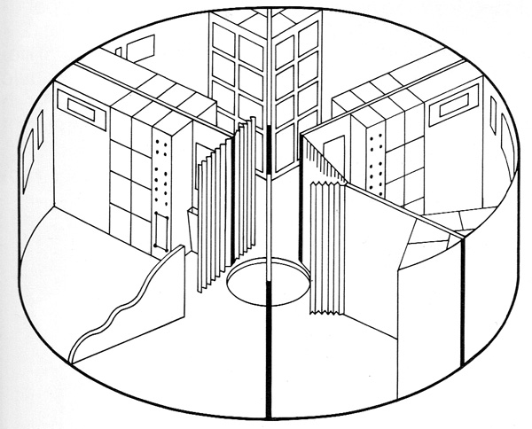
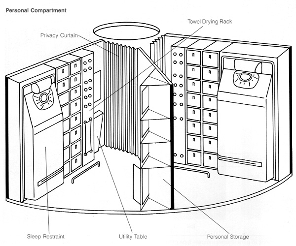
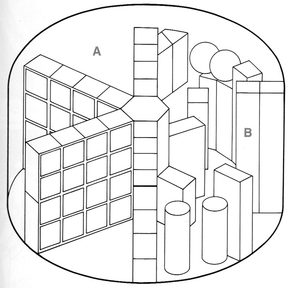
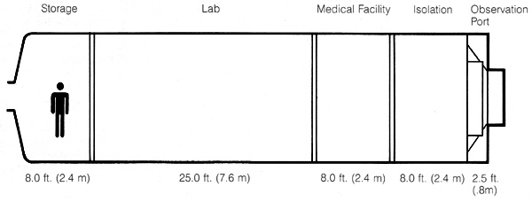
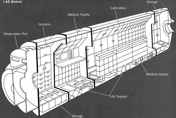
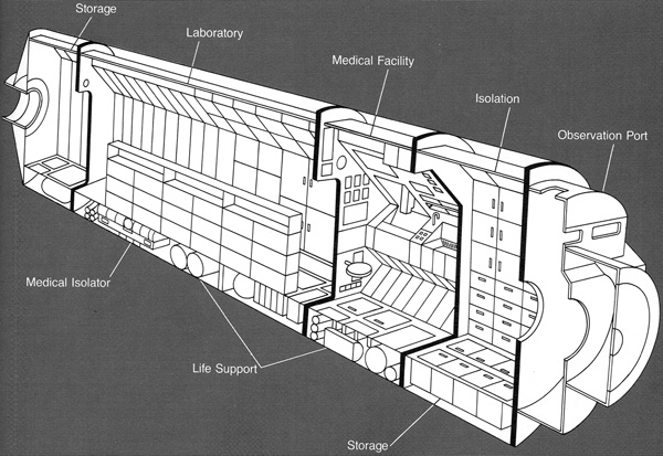
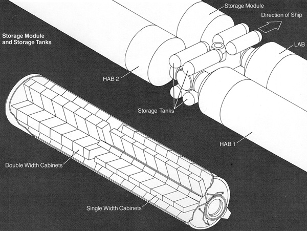


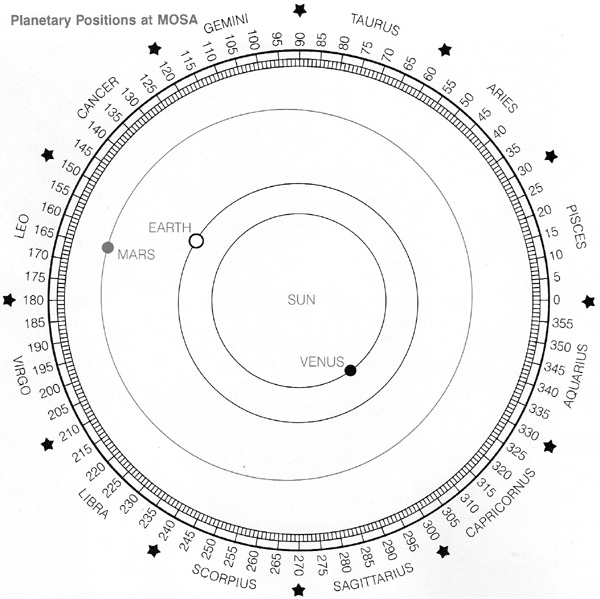
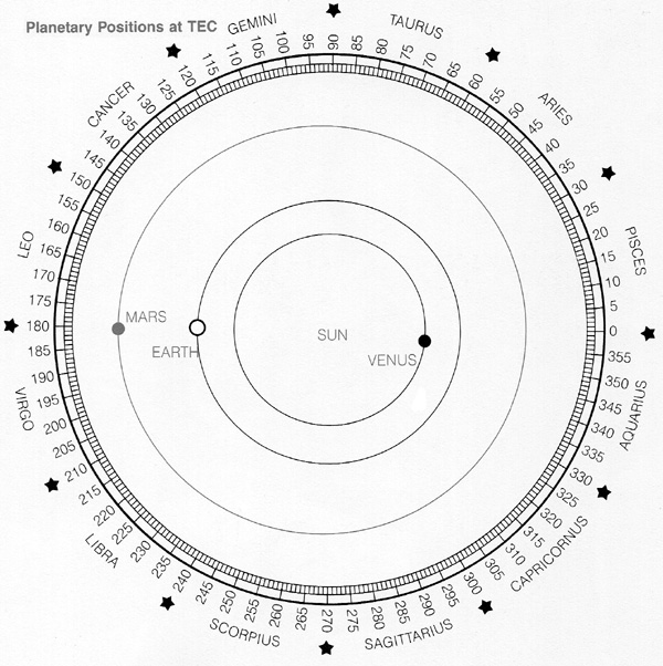

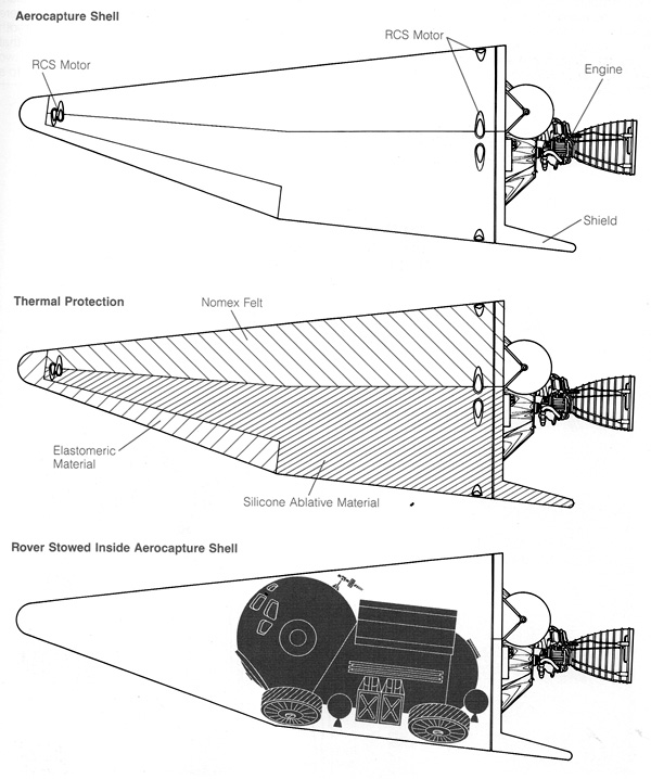
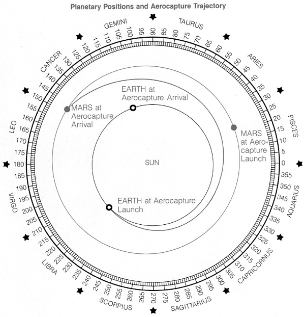
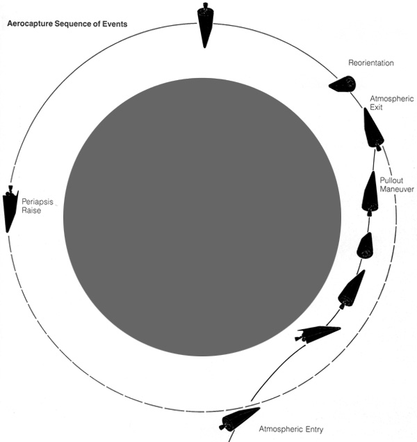
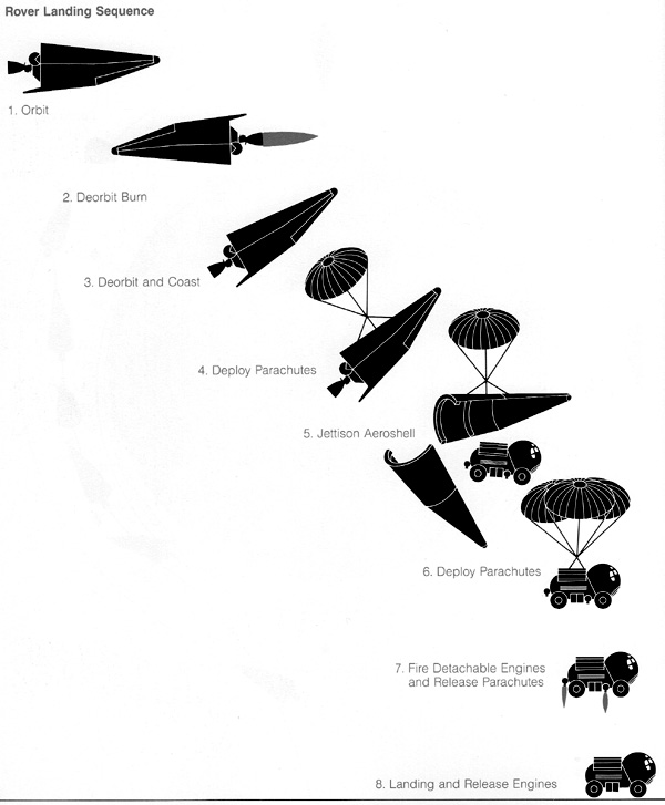

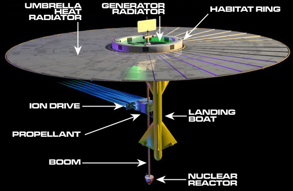
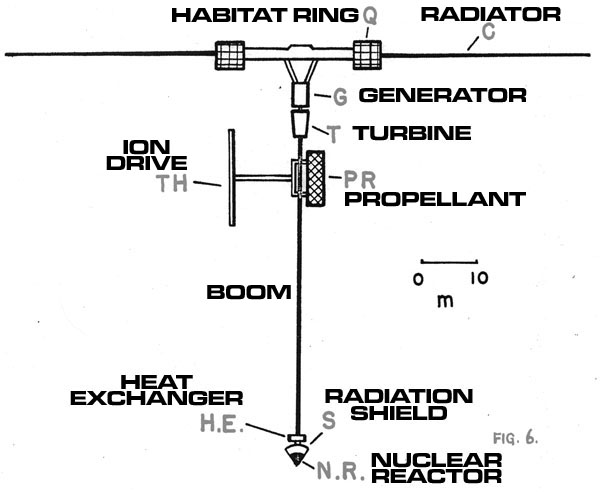
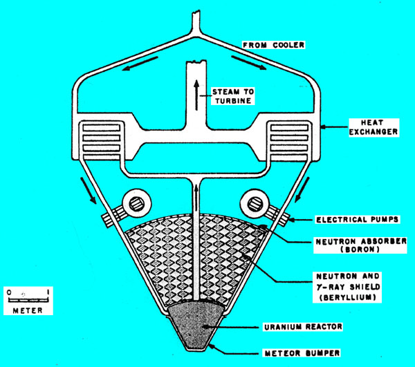
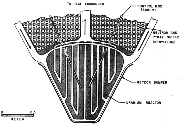

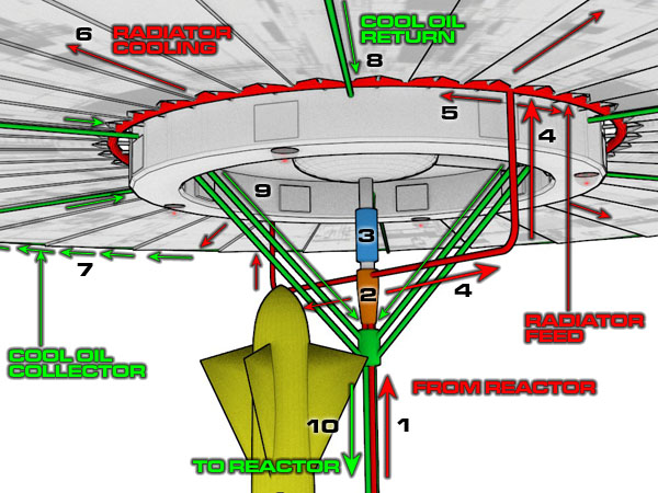

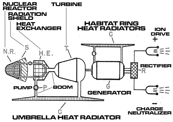
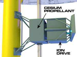
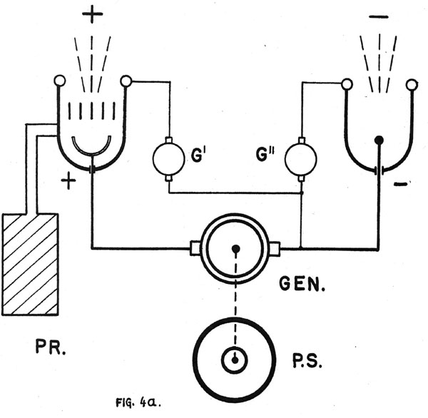
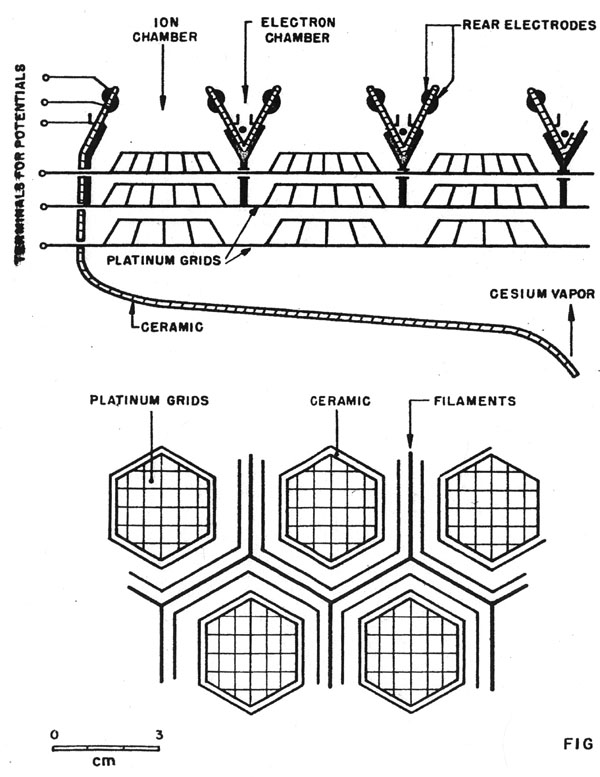
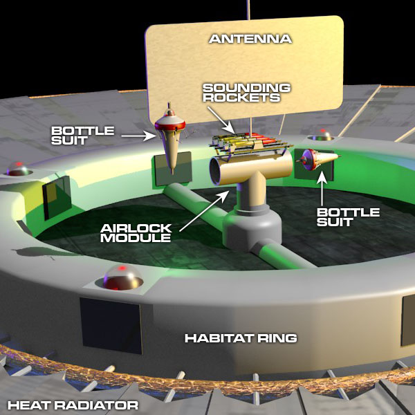

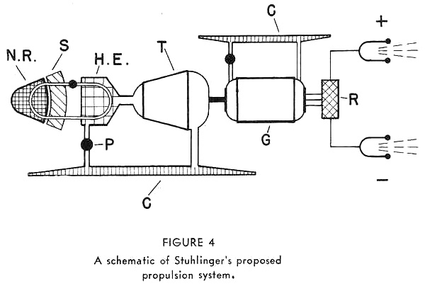
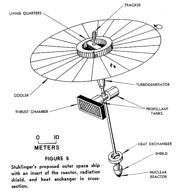
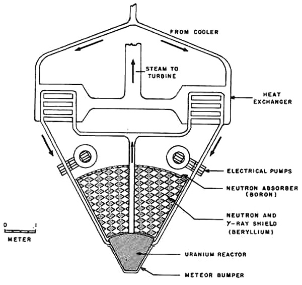
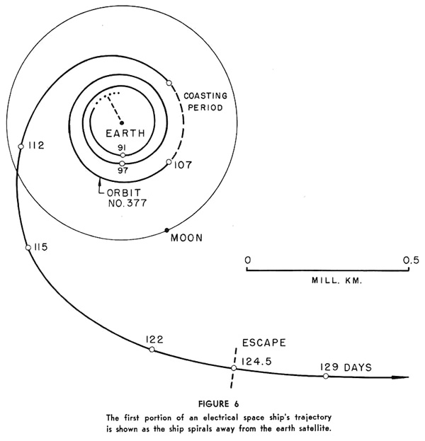


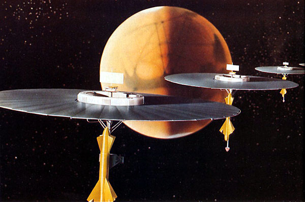
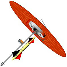
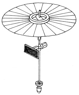
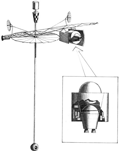
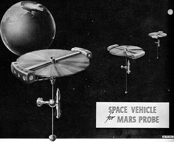

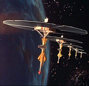
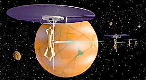
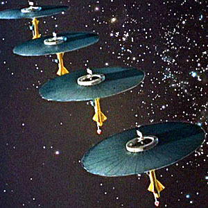
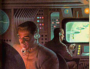
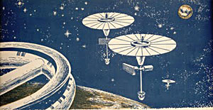
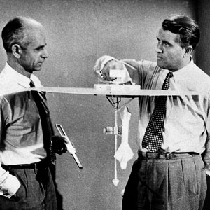
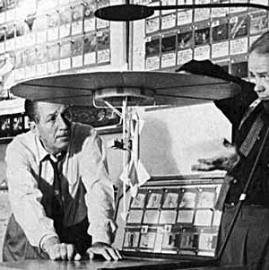
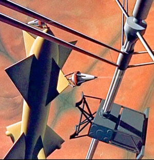
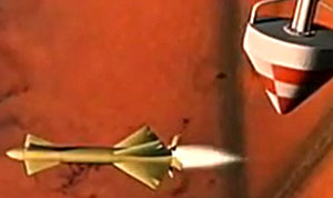
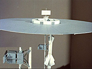
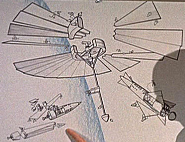
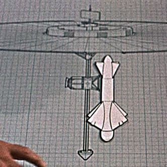
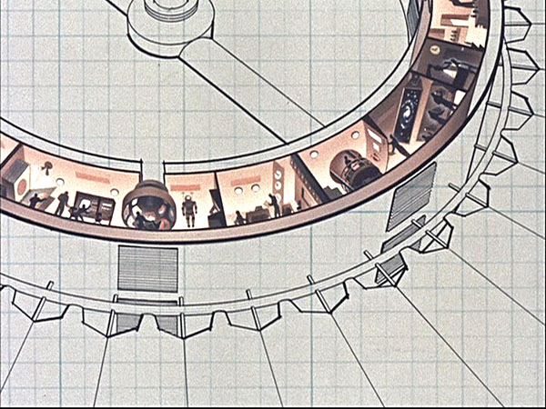
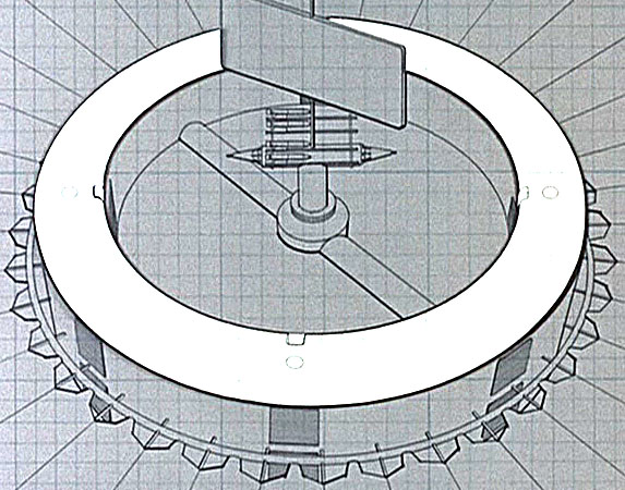
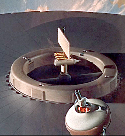
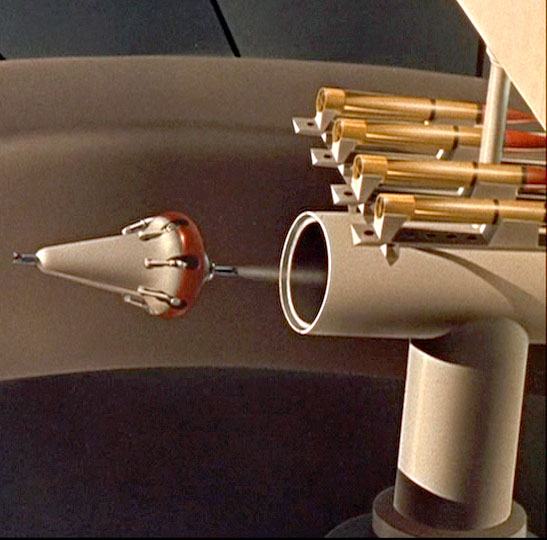

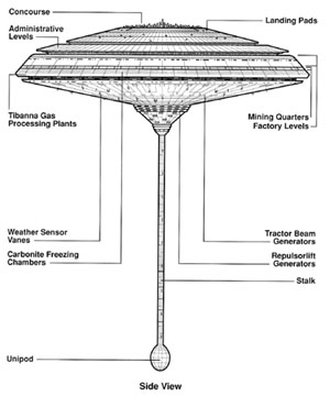
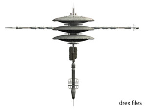


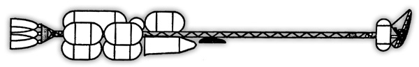
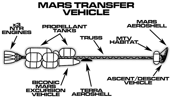


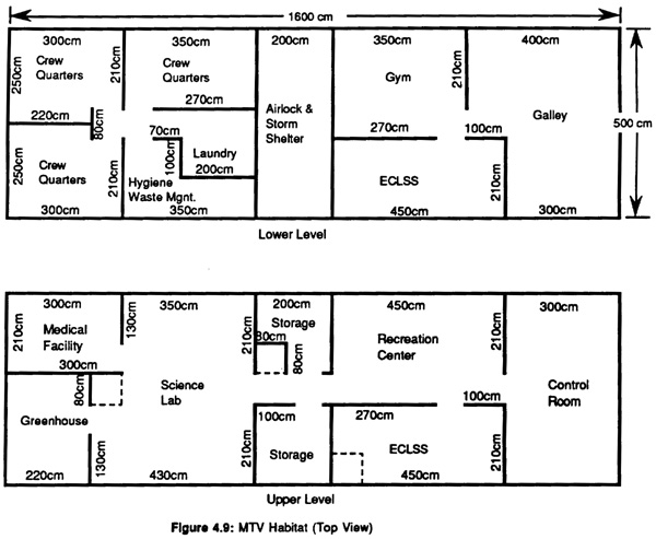

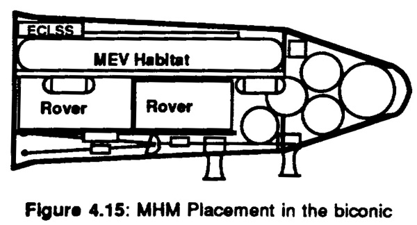
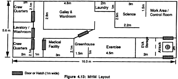

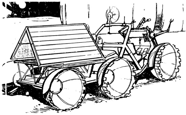


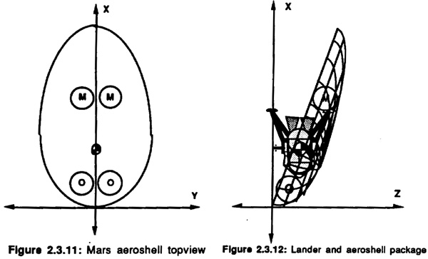


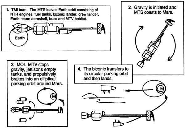
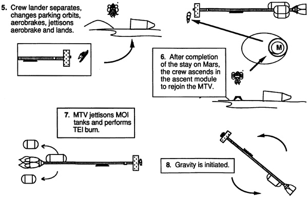
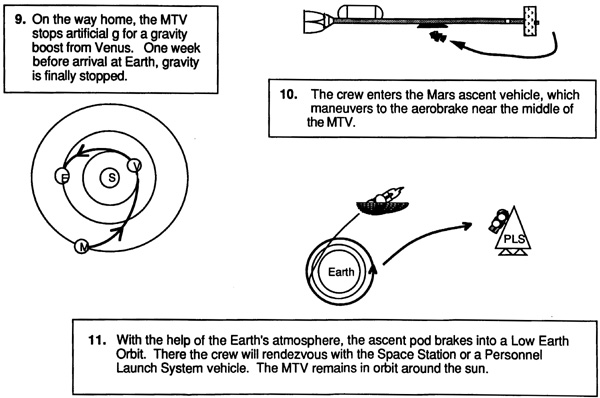
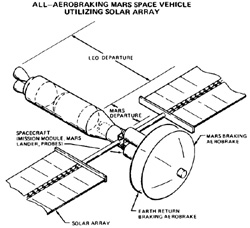

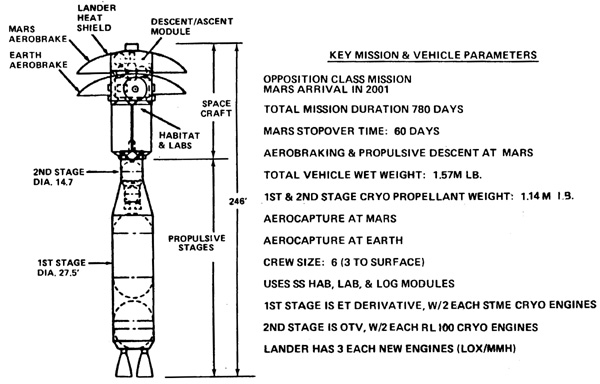

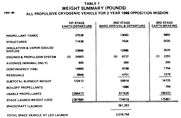
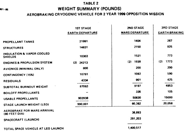
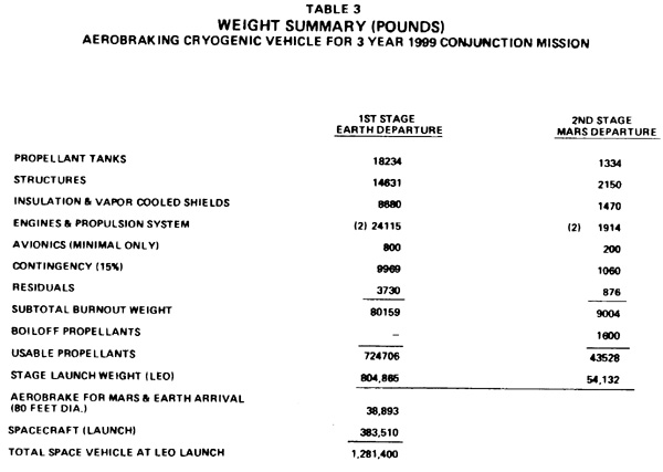
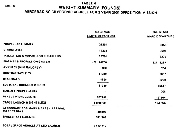
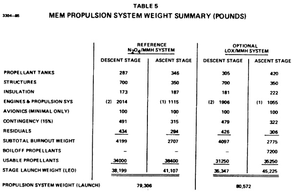
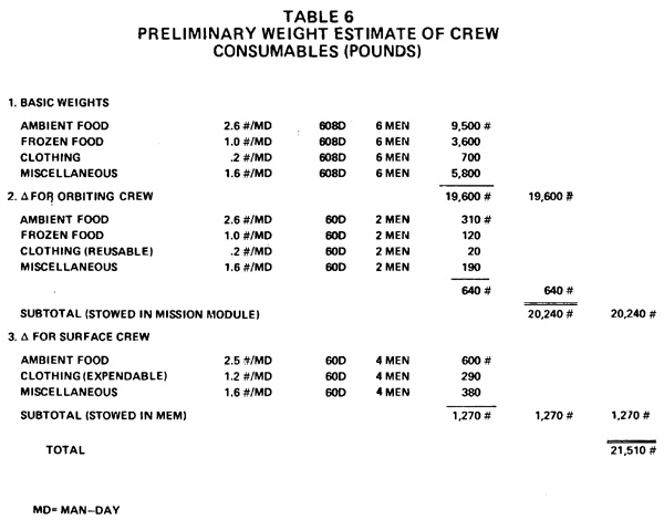
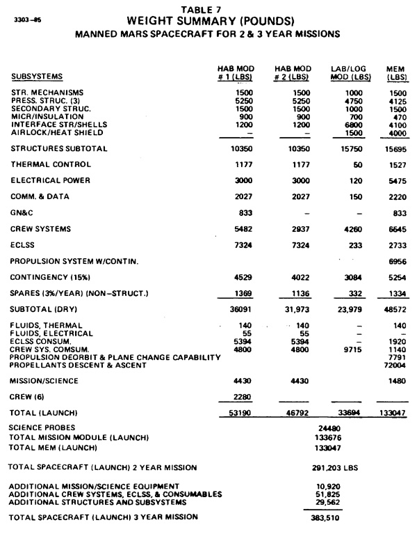


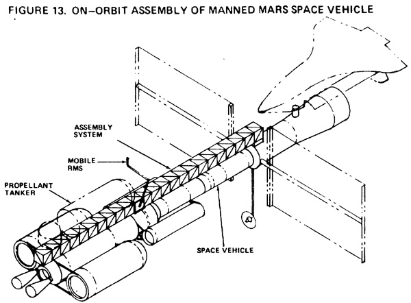


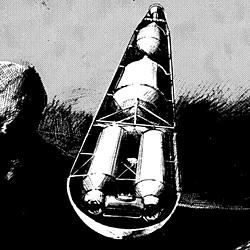
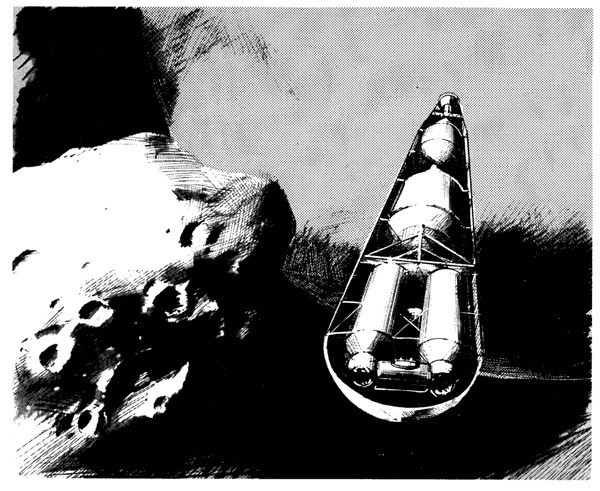
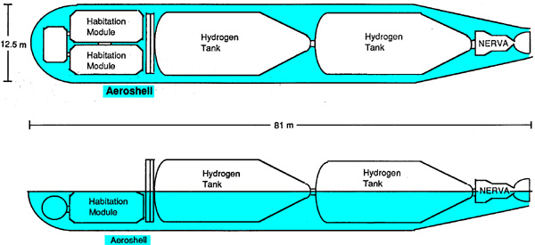
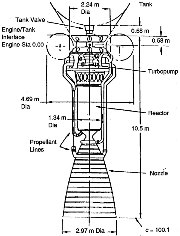
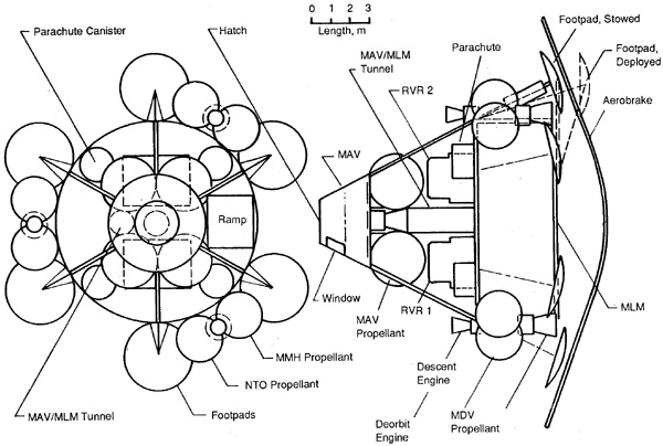
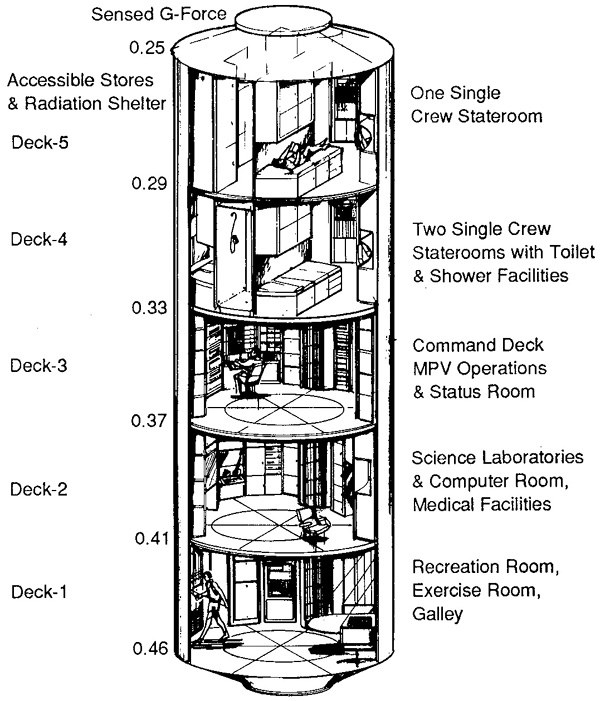
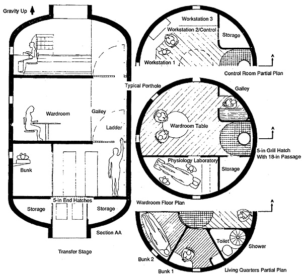
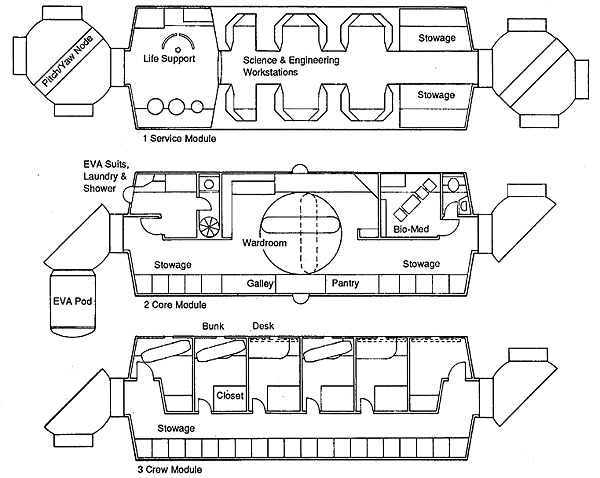

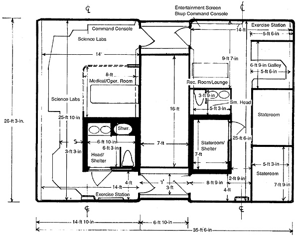
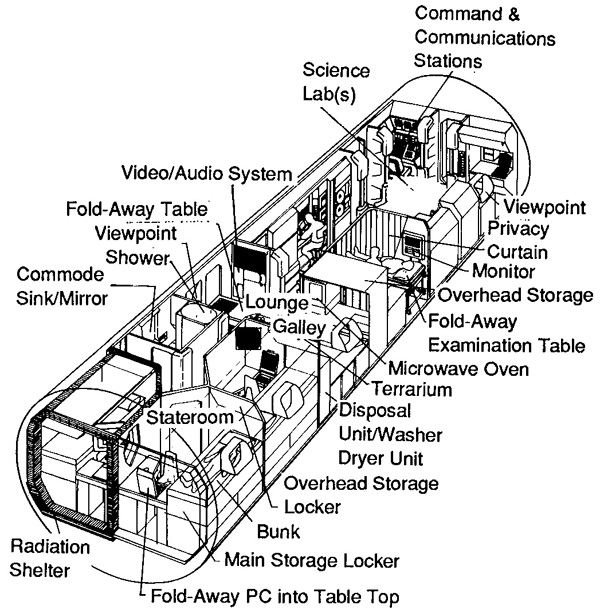
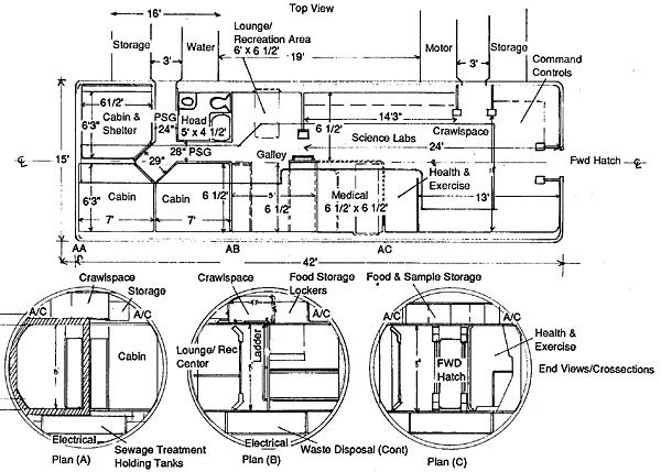
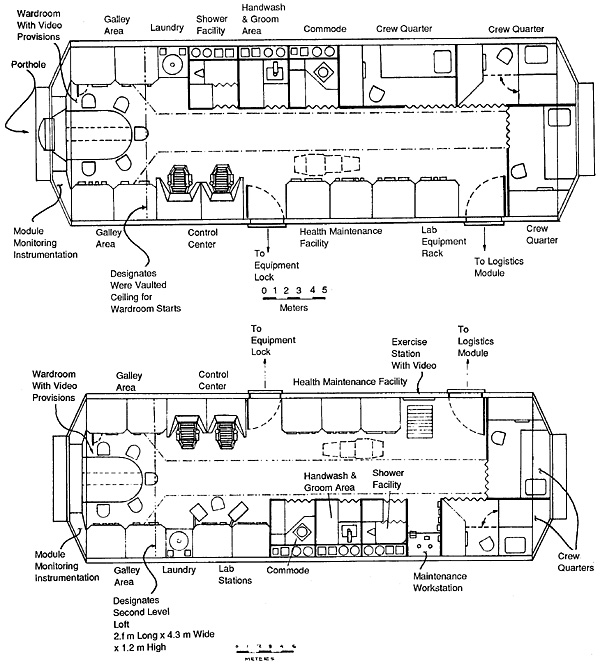
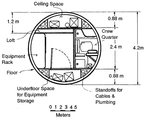
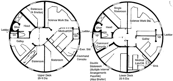
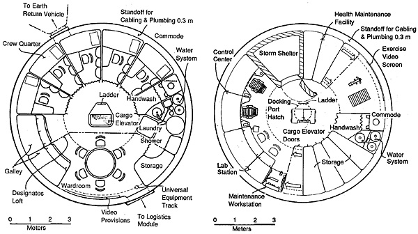
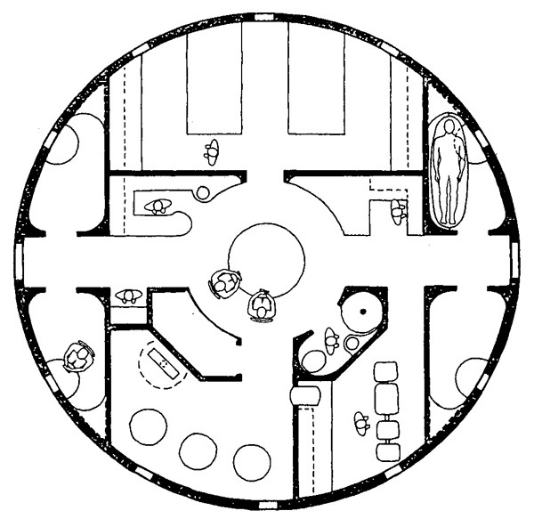
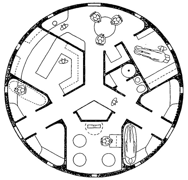
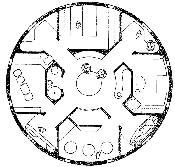
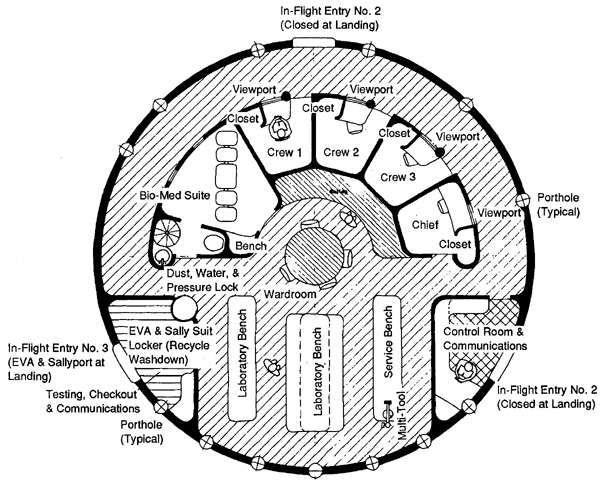
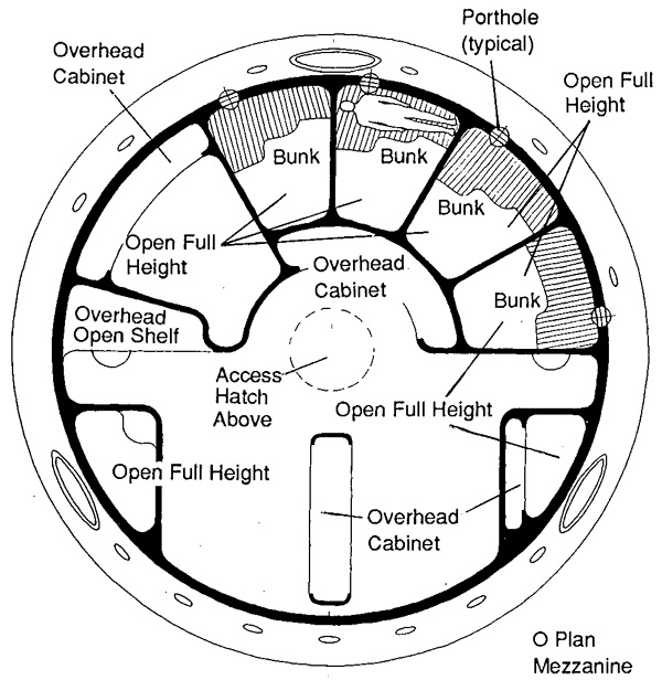
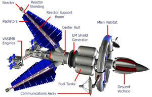

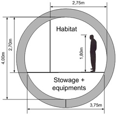
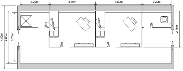
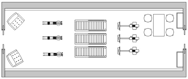
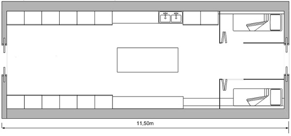
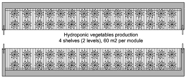


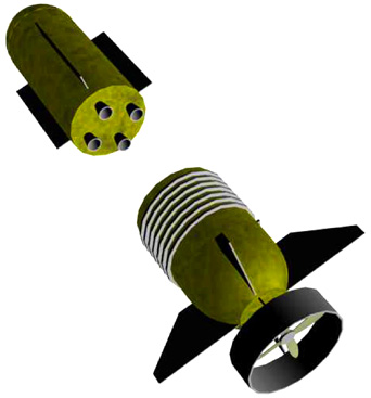
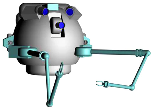


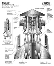
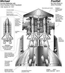
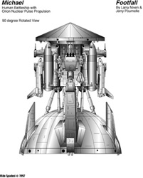
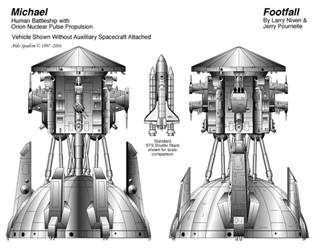
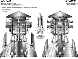
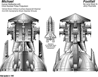


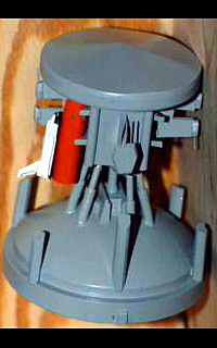
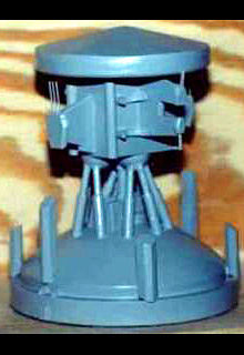

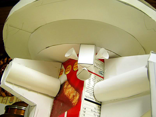
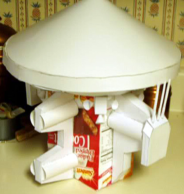
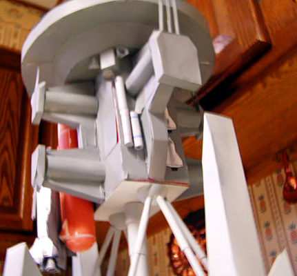
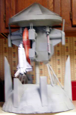


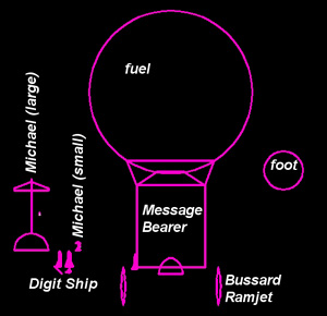
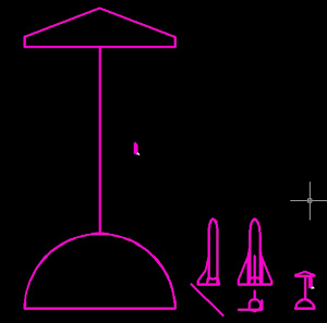
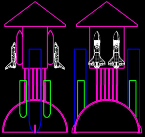


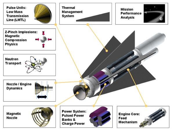
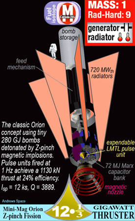
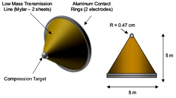
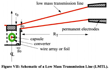
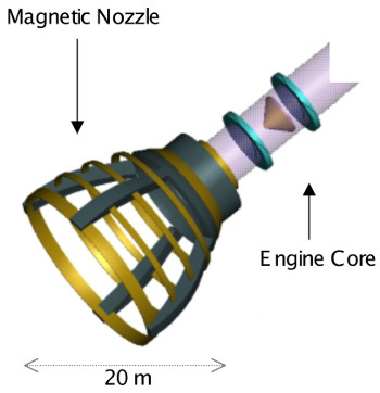
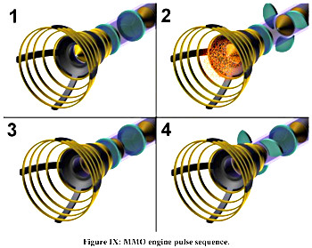


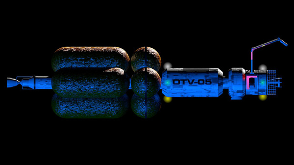

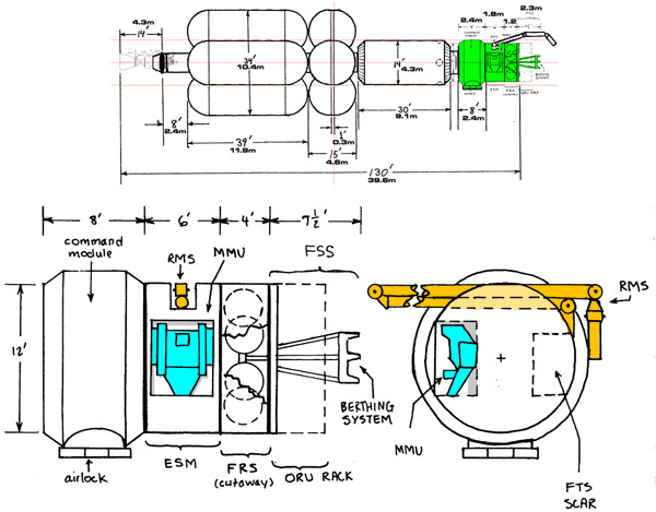
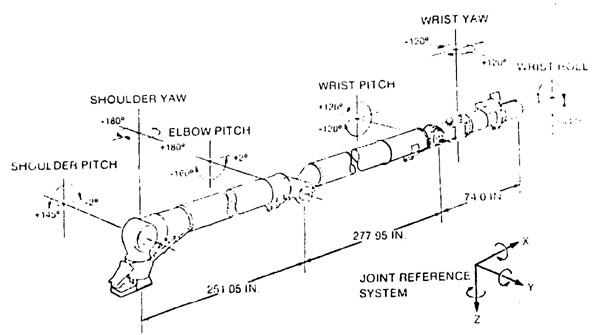
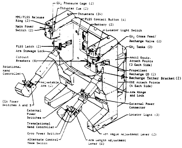
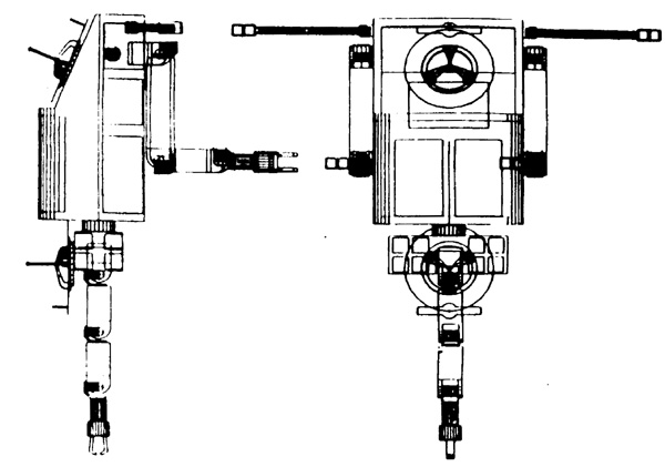
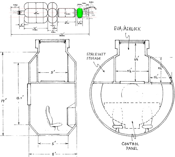
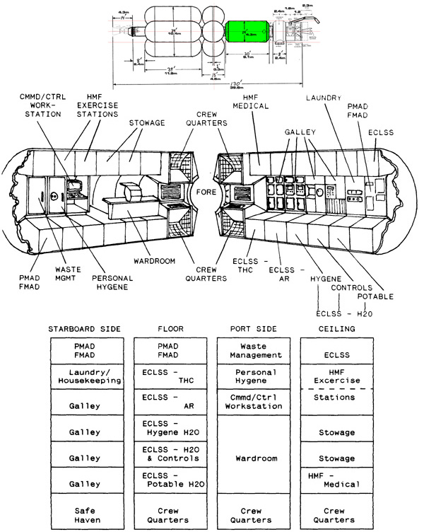
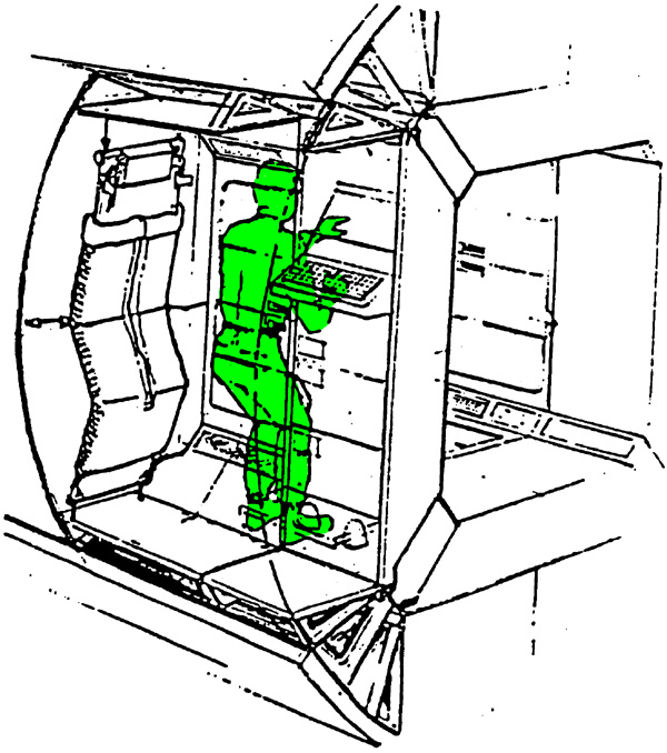


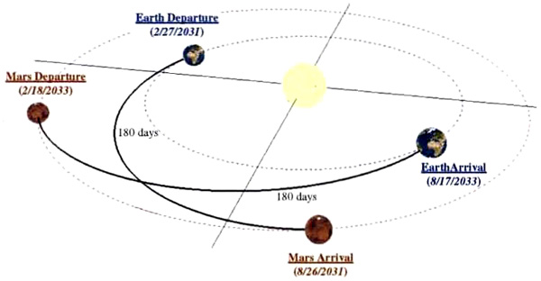
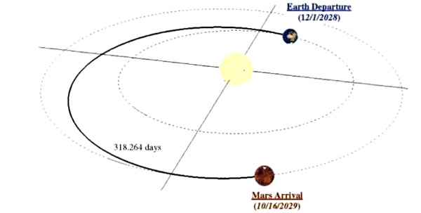

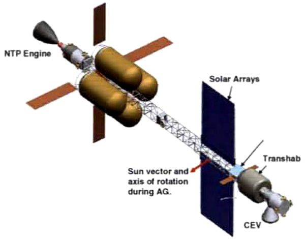
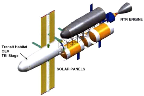
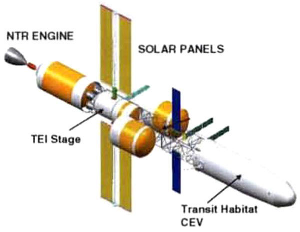
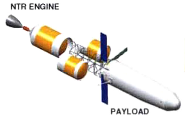
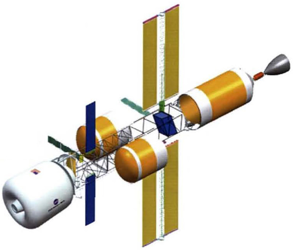
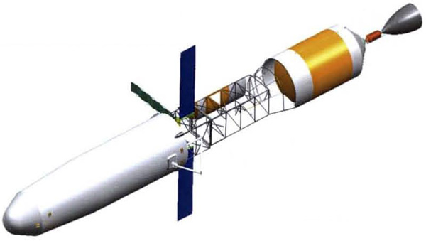

