The section of the spacecraft that the crew lives and works in is called the Habitat Module (Larry Niven calls it a "Lifesystem"). It is pressurized with a breathable atmosphere, and protects the crew from extremes of temperature and from radiation.
Unlike spacecraft in TV and movies, most of a spacecraft is not pressurized. The vast majority of the ship is composed of the propellant tanks, rocket engine, and power plant; all exposed to airless space. The pressurized habitat module is sort of tucked into some convenient corner. Remember rockets are not hotels.
Because every cubic meter of habitat module has to be pressurized and protected from the space environment, interior volume will be at a premium. Due to mass constraints, spacecraft designers will have no choice but to minimize the volume. Which will of course make them very cramped.
But don't make them too cramped or the crew will start suffering psychotic breaks and go berserk.
Whenever I think of space warships, I end up thinking about early destroyers and torpedo-boats; mostly propulsion/fuel, with everything else crammed in the gaps, Nyrath.
As an aside: I find the bow-bulge an unlikely design problem. The bow section of a Battlestar doesn’t contain the main weapon system, or the drive system (either FTL or sub-light), or anything for flight operations, which is to say that it is neither the primary weapon system, nor the primary propulsion system. It mostly seems to house crew and command spaces. Looking across naval design over the centuries from oars to sails to nuclear reactors, one of the few constants is that the overall shape and profile of the ships are dictated by propulsion and armament (with crew facilities essentially jammed in ‘wherever they fit’). So it is a bit baffling what in the bow section is so important that it was worth over-sizing the bow and thus partially obscuring the main battery to fit in. Speaking from historical designs, anything in the bow section is likely to be compromised to preserve the main battery’s firing angles.
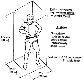
A useful document when designing these things is Human Integration Design Handbook. This include info on the minimum volume needed for such tasks as exercise and hygiene, habitability functions, architecture, hardware, crew interfaces, and EVA.
Upper end models will have a with Closed Ecological Life Support System, cheaper ones will have life support that requires periodic resupply of food, water, and air.
The various NASA studied for Human Outer Planet Exploration designs use NASA's TransHab habitat module. This is because TransHab came from a NASA study, and the module is easy to add to a spacecraft design. Just plug and play.
Maw and Paw Kettle might go homesteading in the asteroid belt, using a habitat module instead of a Conestoga wagon. For a fee the Wagon Train space company could haul the Kettle's module out to the belt.
A major consideration behind constructing a spacecraft that is often glossed over is the brain of the spacecraft. In most cases, this is a crew module, or a remote control module relaying orders from somewhere.
The reason crew compartments don’t receive the same amount of consideration, as say, the engines or the weapons, is that crew compartments have no real surprises about their design, and on larger capital ships, they are rarely a bottleneck in terms of mass, volume, power usage, or heat dissipation...
...But just how few people can you cram into a spacecraft? Modern Supercarriers crew over 4000 people in 25 decks. In space, most of that space would be propellant tanks, and you can’t really dedicate much mass to the crew compartment. Capital ships in space would run only skeleton crews, with only small sections of the spacecraft pressurized.
In space, crew modules are somewhat massive, yet systems like radiators, armor, and weapons usually take up far more mass.
Volume is the main problem with crew modules. Crew modules are mostly empty space filled with air. Even when you pack your humans in like sardines, the majority of the crew module remains empty space. Aside from the propellant tanks, crew modules take up the most volume of any module.
This makes Modern Nuclear Submarines the closest analog to spacecrafts in terms of crew: somewhat over 100 crew for a submarine over 100 meters long.
However, nuclear submarines are fully pressurized, while spacecrafts would not. This means spacecrafts would have even less space for people, and so crew requirements were estimated at roughly half that of a modern nuclear submarine. Of course, some jobs you can’t simply halve, and larger ships with more systems require more crew.
(ed note: Coyote Westlake is in a small habitat module attached to the asteroid AC125DN1RA45, with her ship the Vegas Girl parked nearby. When she wakes up, she is startled to discover that the Vegas Girl is now far away from the asteroid.)
She stood up, as carefully as she could, and tried
to think. When she had gone to sleep, her hab shed
had been bolted to the side of asteroid
AC125DN1RA45, a tiny hunk of rock less than half a
kilometer across, far too small to generate any
gravity field worth mentioning. Maybe a
ten-thousandth of a gee, tops. Now, suddenly, she
was in a gee field hundreds of times stronger than
that (0.05g). What the hell was going on? Had someone
moved her hab shelter for some reason?
Her shelter was a cylinder about fifteen meters
long. Or, now, fifteen meters tall, with Coyote
standing on the bottom looking up. At its
midsection was an airlock system. There were two
viewports at the midsection as well, one set into the
airlock and the other set into the bulkhead
opposite. One port afforded a view of the asteroid’s
surface, the other a view spaceward. What she
couldn’t see through the ports she ought to be able
to see using the remote-control exterior camera.
The camera’s controls were set into the wall by the
airlock.
And starting to get very scared. This was a
budget hab shelter. It had no radio powerful enough
to call for help. No escape pod, either. And without
a ship, she had no way off this rock.
All of the decks where human beings work will be inside a pressurized habitat module, so the crew can go about their business without dying. But more so that other decks, the crew deck design will run afoul of the limitations of the habitat module. Specifically, while a pilot control station or an astrogator's workspace can get away with being very cramped, the crew deck cannot be too cramped or the people will undergo psychotic breaks and go on a rampage.
Depending upon the mass limits and the whim of the spacecraft designer, the crew may not have rooms, just sleeping bunks stuck wherever there is some spare room, or to maintain ship balance. And their may not be enough bunks for the entire crew to sleep at once, forcing a "hot bunk" rotation system (i.e., pairs of crew members on different shifts will share a common bunk).
If the designer is feeling more merciful, they may upgrade the luxury to something resembling those "capsule hotels" popular in Japan. The good news is that you have the privacy of a room. The bad news is that the "room" is only slightly larger than a coffin. If you are really lucky the coffin will include an emergency air supply.
Typical 1 person capsule units in such hotels have an internal volume of 2.7 cubic meters, and are 2.04m long × 1.158m wide × 1.138m tall.
Actually, "cabin" is somewhat of a misnomer for this crew quarter. Coffin or closet might be more appropriate, since this is approximately the size of the room. The cabin is intended to serve as a sleeping berth more than anything else, and though it is equipped with a complete computer terminal and minimal hygiene facilities, it is expected that the crew will spend most of their off-duty time in the small commons.
The cabin is intended for use both under acceleration and under micro-gravity. One side is a padded surface with built-in restraints, while the other walls have only a few cushions and pads to protect the occupant as he moves about.
Though the standard crew cabin does not have an independent life support system, it is reasonably airtight and can function as a short time emergency survival shelter (the exact length of time depending on the number of people jammed inside and the quality of the atmosphere.)
The Jovian Confederation ship books have spacecraft designs that are remarkably scientifically accurate and will repay careful study. The accuracy is due to precise oversight by Marc Vezina.
Most luxurious of all is a room actually big enough to turn around in. This is still going to be tiny. Bunks and tables will fold up against the wall, and one won't be able to fold down everything simultaneously. Do some research on accommodation found in wet Naval vessels. For enlisted men, the US Navy manages to cram twelve crewmen into 100 m3, or 8.3 m3 per man. On a sleeper railroad train, it is a more expansive 10 m3 per person, once you add in the diner, baggage and lounge cars (150 m3 per car, 4 passenger cars, 1 diner, 1 baggage, 1 lounge equals 1050 m3 for about 100 people).
Keeping a sense of rank having its privileges, it is very likely that the accommodations for the officers will be one step above that for the enlisted men. But you knew that already.
Again, keep in mind that this is just the personal living space for the crew, not the entire habitable volume of the spacecraft. By the same token, the personal living space for the crew includes both the crew quarters and a common lounge area.
Crew quarters in 0g. Minimal room for sleeping, working, and rest, done in the same space. Medium duration
mission (< 6 months).
From Human Integration Design Handbook
Partial-gravity crew quarters. Minimal room for sleeping and resting for medium duration (< 6 months). Shared or private quarters. No hygiene or waste manement.
From Human Integration Design Handbook
Partial-gravity crew quarters. Large volume for long-duration missions (> 6 months). Private quarters. Working, sitting, standing, sleeping
combined with hygiene, stowage, and waste management
From Human Integration Design Handbook
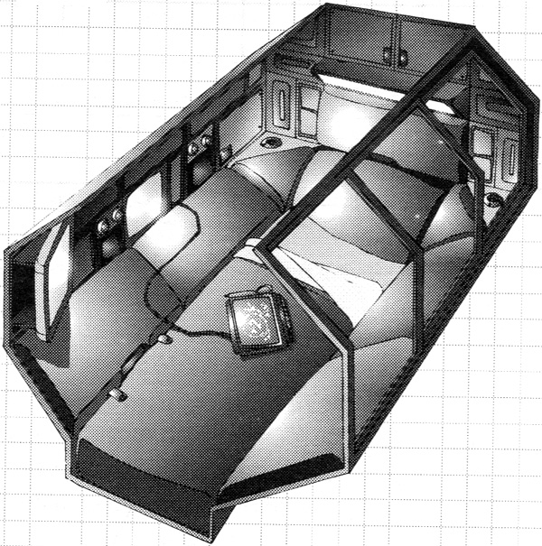
NASA Space Station - Deck 4. Living Quarters Sample quarters to house one crewperson. About 1.8 meters by 2.4 meters. Quarters are given the illusion of being larger by using bright colors and simple uncluttered design. Note restraint bar across legs. Walls look like 1970's wood paneling but I'm sure it is actually Con-Tact self-adhesive plastic wallpaper. Image courtesy of David Portree
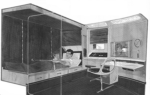
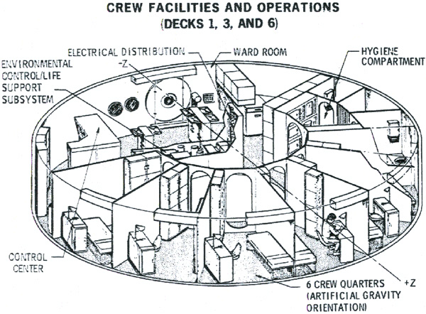
McDonnell Douglas Phase B space station - Decks 1, 3, and 6
Each stateroom has 4.6 square meters of floor space. Each has a small viewport to watch Earth, a folding bunk, a desk, and a storage cabinet for personal belongings.
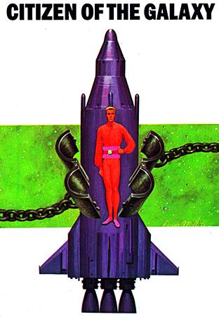
artwork by Davis Meltzer
Presently Thorby became sleepy. But, although he had mastered the gesture by which doors were opened, he still could not find any combination of swipes, scratches, punches, or other actions which would open the bed; he spent that night on the floorplates... ...She moved restlessly. "Thorby, would you mind if I sat in a chair? I don't bend as well as I used to." Thorby blushed. "Ma'am . . . I have none. I am dis —" "There's one right behind you. And another behind me." She stood up and touched the wall. A panel slid aside; an upholstered armchair unfolded from the space disclosed. Seeing his face she said, "Didn't they show you?" and did the same on the other wall; another chair sprang out. Thorby sat down cautiously, then let his weight relax into cushions as the chair felt him out and adjusted itself to him. A big grin spread over his face. "Gosh!" "Do you know how to open your work table?" "Table?" "Good heavens, didn't they show you anything?" "Well . . . there was a bed in here once. But I've lost it." Doctor Mader muttered something, then said, "I might have known it. Thorby, I admire these Traders. I even like them. But they can be the most stiff-necked, self-centered, contrary, self-righteous, uncooperative — but I should not criticize our hosts. Here." She reached out both hands, touched two spots on the wall and the disappearing bed swung down. With the chairs open, there remained hardly room for one person to stand. "I'd better close it. You saw what I did?" "Let me try." She showed Thorby other built-in facilities of what had seemed to be a bare cell: two chairs, a bed, clothes cupboards. Thorby learned that he owned, or at least had, two more work suits, two pairs of soft ship's shoes, and minor items, some of which were strange, bookshelf and spool racks (empty, except for the Laws of Sisu), a drinking fountain, a bed reading light, an intercom, a clock, a mirror, a room thermostat, and gadgets which were useless to him as his background included no need. "What's that?" he asked at last. "That? Probably the microphone to the Chief Officer's cabin."
(ed note: one hex module is a hexagonal prism, about 3.7 meters wall to wall (12 feet), 15.2 meters long (50 feet), and has a volume of 241 cubic meters (8,500 cubic feet)
The living quarters were on the outboard end of the med module. In accordance with Tom's requests— made on the basis of his earlier experience in LEO Base—each member of the team had a private sleeping sector. None of these "cabins" was spacious, each being a one-sixth sector of the hexagonal cross-section of the module, minus the hexagonal tunnel down its middle, and eight feet (2.4 m) in length. "Good heavens! We're supposed to live here?" Angela asked, aghast at the cramped aspect of her cabin and its 24-inch (0.6 m) sliding pressure door. "Well, I had about as much room in a destroyer," Stan remarked. "And some people had even less room on the smaller nonnuclear submarines." "Actually," Fred Fitzsimmons remarked, "we've got it plush, gang. We've got our own cabin. Most of the construction crews have to work on the hot-bunk system and can use their cabin only during their sleeping shift." "But it's so small!" Angela pointed out. "What do you mean, 'small'? It'll get much bigger as you learn how to live in zero-g, Angela," Fred commented. "You've got more than a hundred-fifty cubic feet (4.3 m3) of space. A coffin's only about thirty cubes (0.9 m3), and that's all it takes to hold a human being." "Oh, thanks for the comparison!" Dave remarked. "We're all spoiled," Tom pointed out to his crew. "This is sheer luxury compared to the way most people on Earth live. Take Southeast Asia, for example—" "You take it, Doc. I've been there," Stan pointed out. Each cabin had its own lighting system, its own emergency life-support system in addition to the air ducts leading to the main GEO Base life-support system, a sleeping sack, and lockers to hold clothing and personal effects. Each cabin door could be closed and sealed from within and from without, but could be opened in an emergency from the main module control center panels. The sixth sector of the module was a lavatory. The living quarters themselves occupied only eight feet (2.4 m) of the length of a fifty-foot (15.2 m) hex module. Eight more feet (2.4 m) of length were occupied by a stand-by lavatory in addition to two segments devoted to dedicated module life-support and power-distribution equipment. The remaining nine feet (2.7 m) of the outboard half of the module was an open common room. The common room had a feature not present in any of the living cubicles: a 12-inch (0.3 m) triple-glazed port.
From SPACE DOCTOR by Lee Correy (G. Harry Stine) (1981)
There had been a time when living space had been a privilege of rank aboard a ship of war. Richard had once read that Christopher Columbus’s cabin consumed half the living space aboard the Santa Maria. No longer. His cabin was no larger than that of any other officer, and actually smaller than the cabins provided enlisted personnel — although, to be fair, enlisted ranks were bunked four to a compartment. There was just enough space in Drake’s cabin for one person to dress comfortably. It took the two of them longer to wash, dress, and make themselves presentable than he would have thought possible.
As in Sanctuary Asteroid, Braedon’s position as expedition commander gave him clear title to the most luxurious quarters aboard ship. As had been the case in the asteroid, luxury aboard Procyon’s Promise was only a relative thing. The expedition commander’s quarters consisted of two adjoining compartments. The larger of these served as both office and living quarters, while the smaller was devoted to sleeping. A tiny bathroom was separated from the sleeping cabin by a folding door. Even though the cabin was small, Promise’s designers had done their best to maximize its utility. All furniture folded into the bulkheads or overhead when not in use. Numerous lockers, in which Braedon stored his books, papers, clothing, and personal vacsuit, lined the walls.
The US wet Navy crams twelve enlisted men into 100 m3, or 8.3 m3 per man.
On a sleeper railroad train, it is a more expansive 10 m3 per person, once you add in the diner, baggage and lounge cars (150 m3 per car, 4 passenger cars, 1 diner, 1 baggage, 1 lounge equals 1050 m3 for about 100 people).
In this NASA report (Preliminary Assessment of Artificial Gravity: Impacts to Deep-Space Vehicle Design 2007) it implies that for the entire habitable volume the bare minimum is about 17 m3 per crewperson. Part of that will be the crewperson's bunk space, the rest is their contribution to the common lounge area.
However, in this later 2015 report (Minimum Acceptable Net Habitable Volume for Long-Duration Exploration Missions) recommended a minimum acceptable Net Habitable Volume of 25 m3 (883 ft3) per person.
The 2015 report makes a few assumptions and definitions.
Net Habitable Volume means “the volume left available to the crew after accounting for the loss of volume due to deployed equipment, stowage, trash, and any other structural inefficiencies and gaps (nooks and crannies) that decrease the functional volume”. This means a large room crammed floor to ceiling with food rations doesn't count.
Minimum Acceptable Net Habitable Volume has a long and complicated description that you can read in the report. What it boils down to is the minimum volume that will allow the crew to not become stir-crazy and go postal in a homicidal rampage.
The report assumes a baseline mission based on the NASA Mars Design Reference Architecture 5.0. A 30 month mission, 6 crew, mixed gender and culture, up to 22 minute communication delay (one-way) with Terra, autonomy from the ground increases with distance from Terra.
For purposes of illustration, the International Space Station has about 916 cubic meters and 6 crew. This gives each crew member a luxurious 153 cubic meters.
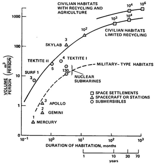
Personal space required by people. Numbers above squares, triangles, and circles are the population size of the given habitat. Example: the military nuclear submarine has a crew size of 130, a mission duration of 5 months, and 10 cubic meters per crew member.
Chart from a paper by Edward Bock, Fred Lambrou, Jr. and Micael Simon(1977).
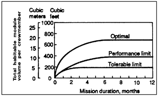
Below the Performance limit the crew productivity suffers due to claustrophobia.
Below the Tolerable limit the crew eventually undergo a psychotic break and kill each other. Image courtesy of NASA (1995).
Spacecraft Volume Per Person over Mission Duration Chart by Steven Pestana (2016), first step in reproducing Howe & Sherwood chart above.
Spacecraft Volume Per Person over Mission Duration Chart by Steven Pestana, finished product in reproducing Howe & Sherwood chart.
click for larger image.
Spacecraft Volume Per Person over Mission Duration Chart by Steven Pestana, Interactive version (available here)
click for larger image.
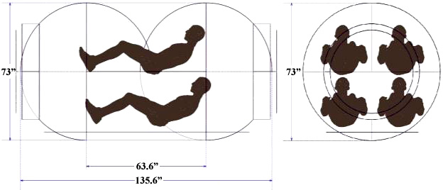
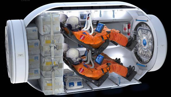
The design problem was to make the habitat module for a Mars Ascent vehicle (MAV), with enough life support to keep four astronauts alive from 3 to 5 days (20 person-days). There would have to be acceleration couches capable of protecting the astronauts from the acceleration stress of a Mars lift-off. It will need facilities for crew sleep, waste and hygiene, a galley, and meaningful crew work. BUT ABOVE ALL IT HAS TO BE AS TINY AND AS LOW MASS AS POSSIBLE. Because every gram counts.
It will be a Minimal Volume Spacecraft Cabin, or MVSC.
Other missions just require the MAV to deliver the astronauts to Low Mars Orbit where they will rendezvous with the main spacecraft or a space taxi. This only takes 12 to 18 hours, which means they wouldn't need a galley, toilet, and 20 person-days of life support. But in this case there was no space taxi, and the main spacecraft was not in LMO.
But it is a great example of an absolute minimal hab module. Which will come in handy since the every-gram-counts principle turns up everwhere.
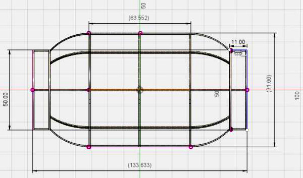
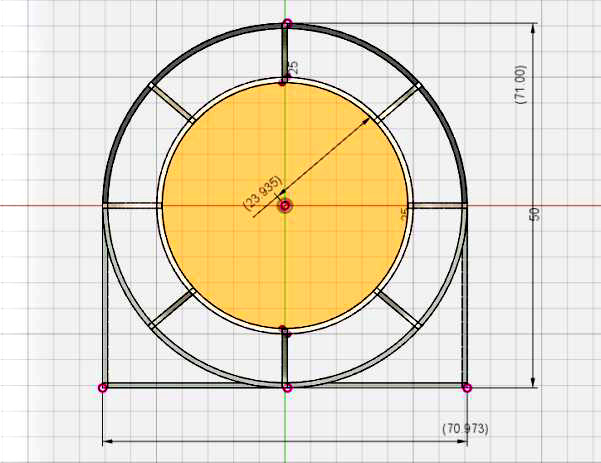
The configuration evolved from placing four almost prone astronauts in a 2 × 2 matrix, inside a horizontal cylinder just big enough to hold them, with hemispherical end-caps. The module turned out to be about 1.85 meters (73 inches) in diameter, and 3.4 meters (134 inches) long.
The MVSC has dual docking ports, one in the front and one in the rear of the cabin. These contain one meter square hatches framing a NASA Active-Active Mating Adaptor, though you could swap these for other docking adaptors depending upon what becomes the standard. Between the hatch and the maramon flange are utility connectors. So once docked the MVSC is connected to the other vessel's power supply and data net. Sort of like pluging in a USB cable. The two docking ports are identical so either can be used.
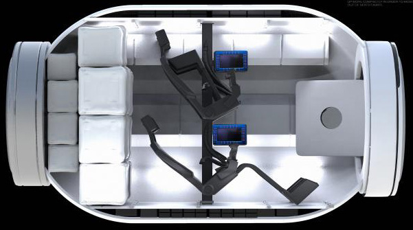
The crew seats are supported by one or more vertical struts positioned between the port and starboard set of seats. The seats can fold shut when not in use to make more free space. The seats can also be rotated to face the opposite direction.
Each seat has a computer display and controls. This study didn't go in to depth on what controls would be added, but they figure each seat will have a control-set containing:
Single edge key display (I guess this means an flat-screen display with a row of dedicated buttons along one edge)
Cursor countrol device mounted on the arm-rest (captive mouse or track-ball)
There will also be an "auxiliary interface port" (i.e., a USB port) so you can jack in peripheral devices, like a flash drive or something. The controls are part of the seat, so they too can be rotated to face the opposite direction.
Immediately behind the seats is the cargo section. It is designed to accommodate the minimum of consumables, plus 250 kg of Mars surface samples. The cargo section holds two rows of Cargo Transfer Bags (CTBs) which span the width of the cabin.
In front of the seats is an open volume which partially allows the front hatch to swing open. The seats will have to be collapsed to allow the hatch full swing. If the seats are rotated to face the other way, the CTBs will have to be relocated to the new rear section.
The hab module subsystems are distributed along the module exterior, and inside the pressure vessel along the contours of the inner cabin walls. The Environmental Control And Life Support System (ECLSS) ducting provides fresh air at the crew head positions, and also provides umbilical connections to flight suits.
The report does not go into details but I'm sure the facilities for waste disposal and hygeine are Spartan. Probably more or less the same as on the Apollo lunar missions. Plastic bags for urine and feces, moist towelettes for your hands, and the rest of your body will just have to stew in its own juices until you dock with the mothership. Yuck.
The MVSC has many other uses besides being the habitat module for the MAV. The thing is inherently modular, just like the JPL Modular Hab System
Slap on a Reaction Control System (RCS) and you have instant space taxi (the report calls it a "crew transfer cabin"). They note that (with one exception) there has not been a case where two large complex spacecraft have docked. It is always some tiny capsule docking with a large complex spacecraft. Docking two big spacecraft is probably very risky.
A space taxi would be far safer, which is an argument to develop the MVSC. Without 20 person-days of consumbables you could squeeze six astronauts into the MVSC, for a trip that takes half an hour or so. By the same token, with only two astronauts, some of the consumables could be replaced with a real space toilet and a galley, for longer duration missions.
Yes, the proposed NASA MMSEV could also be utiized as a space taxi, but that is over-kill. A MVSC with an RCS sled is far cheaper.
Obviously adding some remote manipulator arms would turn the MVSC into a space pod, and a real rocket engine would make it into a space tug. But now you are actually stepping on the MMSEV's toes. Keep in mind that any rocket engine will mounted "below" the hab module, not over one of the docking ports. This is the same place it will be mounted in a Mars Ascent Vehicle, and will ensure that the direction of "down" will line up with the support provided by the seats.
A MVSC with a rocket engine and two crew could be modified to be a Crew Rescue Vehicle, basically a space ambulance. One crew is the pilot, the other is the medical caregiver. Part of the internal space would be repurposed into a medical treatment area for one incapacitated crew member.
A MVSC with most of the interior fittings removed could be used as a docking tunnel. This would be useful for space stations as well as surface bases. The tunnel is larger than you need for a just a simple pass-through, so it could also be used for stowage, subsystem equipment, or crew workstations. The external hull will also provide additional surface area to site solar arrays, heat radiators, and other whatnot.
Space pods can be used to repair satellites and other orbital facilities. The trouble is that the repairs can take several days and the pods do not have the life support for that. A MVSC can be modified to be a sort of life support depot with docking port for up to two space pods. Different sets of repair tools and replacement parts can be stored and swapped out as needed. Repair crew can dock to the MVSC to get some sleep and recharge their space pod ECLSS. The MVSC seats would be removed, a galley and real toilets added, and maybe even have some polyethylene bricks layered on the hull to turn the MVSC into a storm cellar.
And I'm sure it has occured to you that adding a high-thrust propulsion system and lots of weapons will transform the MVSC into a space fighter.
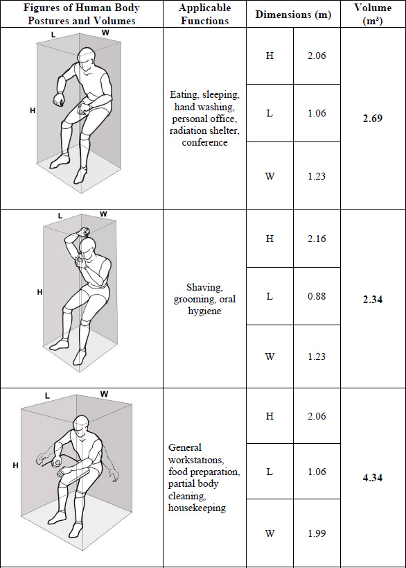
Human Integration Design Handbook
These are from NASA's Human Integration Design Handbook (warning: 42 megs!). As an aide to designing the architecture of a habitat module, they identified certain critical tasks and determined the minimum volume necessary for those tasks.
Inflatable Habitat Module
It is possible to make a habitat module that collapses like a balloon for storage purposes (Inflatable space habitats). NASA's Transhab was designed to temporarily reduce the diameter of the module, since surface-to-orbit booster rockets have all sorts of problems if the payload has a larger diameter than the rocket. Inflatable structures also tend to have a lower mass than a same volume conventional structure, and Every Gram Counts.
Such inflatable hab mods can also come in handy if one was, for instance, transporting a space station to be established in a remote location. Or little space igloos to sell to mom-and-pop asteroid miners. Inflatable hab mods are also central to the Spacecoach concept.
While it sound incredibly dangerous to trust your life to something that will pop at the touch of a pin, it isn't really. A mere pin isn't going to do anything to these modules. Most such modules are constructed from Kevlar or other bullet-proof material. The walls are probably much stronger than that pathetic aluminium foil the International Space Station uses for its hull.
Bigelow Aerospace smelled a business opportunity. It purchased the rights to NASA's Transhab technology, and are busy prototyping pre-fab instant space stations. These Bigelow modules will be incredibly affordable ($100 million dollars each), have a low mass to reduce boost cost, and will collapse small enough to fit the radius of most boosters.
(ed note: Larry Niven uses the term "lifesystem" for habitat module)
Her full name was Slower Than Infinity. She had been built into a General Products No. 2 hull, a three-hundred-foot spindle with a wasp-waist constriction near the tail. I was relieved. I had been afraid Elephant might own a flashy, vulnerable dude’s yacht. The two-man control room looked pretty small for a lifesystem until I noticed the bubble extension folded into the nose. The rest of the hull held a one-gee fusion drive and fuel tank, a hyperspace motor, a gravity drag, and belly-landing gear, all clearly visible through the hull, which had been left transparent...
...We were in the expansion bubble when it happened. The bubble had inflatable seats and an inflatable table and was there for exercising and killing time, but it also supplied a fine view; the surface was perfectly transparent...
...“Let’s go into the extension bubble,” said Elephant. “Let’s not.” “We’ll get a better view in there.” He turned the dial that would make the bubble transparent. Naturally we kept it opaque in hyperspace. “Repeat, let’s not. Think about it, Elephant. What sense does it make to use an impermeable hull, then spend most of our time outside it? Until we know what’s here, we ought to retract the bubble.” He nodded his shaggy head and touched the board again. Chugging noises announced that air and water were being pulled out of the bubble...
...There was just room to get our suits on one at a time. If the inner air lock door hadn’t been open, there wouldn’t have been that. We tried leaving our helmets thrown back, but they got in our way against the crash couches. So we taped them to the window in front of us....
Volume of 16 cubic meters, or just under the 17 m3 minimum volume for one person to stay sane for missions longer than six months.
It has an alpha of 389 kilograms per cubic meter while packed, and 87.5 km/m3 when expanded. Total mass 1.4 metric tons. Keep in mind that the BEAM is a test-bed, an actual practical module will have a different mass.
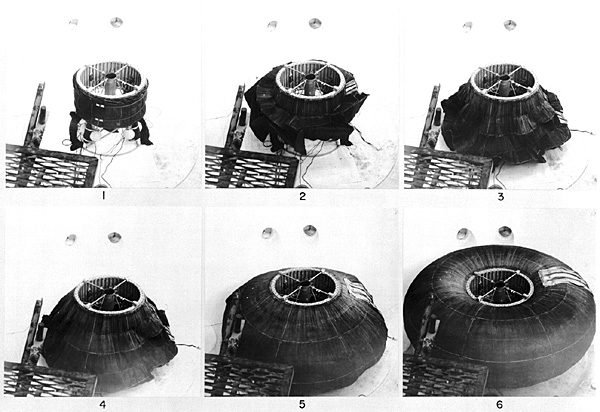
Goodyear inflatable space station
Popular Science December 1962
Inflation. Note inflating gas tanks on right, and stack of Whipple shields on left
Attaching Whipple shield
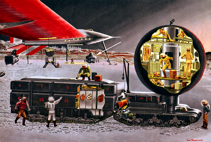
Mars Rover. Sphere is inflatable (note sphere in background being blown up, indicated by the white arrow). Air lock is on central column. Cut away on rear of tractor shows closed-circuit engine fueled by hydrogen peroxide and oil. Cut away on trailer shows fuel supply and cargo.
Image from Can We Get to Mars? Collier's Magazine April 30, 1954
Artwork by Fred Freeman
TransHab
TransHab module
Nuclear rocket with TransHab module
TransHab modified for artificial gravity
TransHab first floor
TransHab second floor
TransHab third floor
The TransHab concept was a NASA project to create an inflatable space station, which is not quite as insane as one would think. The walls include layers of Kevlar, and are probably harder to puncture than the metal walls of the International Space Station. The private company Bigelow Aerospace has purchased the rights to TransHab patents, and is in the process of developing a commercial space station. Bigelow already has launched twoprototypes into orbit and they are working just fine.
The standard TransHab module had a mass of 34,050 kilograms (34 metric tons), an inflated volume of 350 cubic meters, an inflated diameter of 8.2 meters, four levels, and could support a crew of six for about eighteen months.
In the Mars Reference Mission, they had a bimodal nuclear thermal rocket on a Mars mission. The rocket could deliver the mission to Mars, come back to approach Earth but with dry propellant tanks. So the rocket would go sailing past Earth into the abyss while the crew bailed out to be rescued. Bye-bye rocket.
However, if you replaced the relatively massive hard-shell habitat module with a lightweight inflatable TransHab module, the increase in delta-V was enough so that the rocket would have enough extra delta-V to be able to brake into Earth orbit and be re-used.
As you look through the various Realistic Design pages, you will be struck with how many designs use a TranHab. Designers figure it is "off-the-shelf" technology. Certainly Bigelow Aerospace is doing its best to make it so.
There is an online calculator for TransHab modules here.
Troy Campbell pointed me at a fascinating NASA report about spacecraft design. The report shows how much easier it is to design a habitat module if it for a one gravity environment instead of free fall (surprise, surprise). It has the spacecraft separate into two parts connected by tethers, spinning for artificial gravity.
Some of the details of this design cannot be used with, say, a warship. You do not want to used an inflatable habitat module on a ship going into battle. But the lists of required equipment are very useful for your ship designs, as are their masses, volumes, and power requirements.
For its habitat module, the report take a TransHab
inflatable habitat module, and modifies it for one g worth of spin gravity. TransHab modules are low mass since the walls are made of woven Kevlar instead of metal. For the report design, interior suspension cables are added to support the decks (since the basic TransHab is designed for free fall), and an anti-radiation storm cellar added to the core. The other main reason for using a TransHab is because the proposed launch vehicles used to boost the module into orbit had severe payload size limits. The TransHab could fit into the limits while collapsed, then inflated to full size when in space. For your design, you probably will not have such payload size limits, so you will not need to use an inflatable habitat.
To cool off the module, a small heat radiator is wrapped around the exterior. This radiator can only collect and reject 15 kilowatts of heat, since it is only for life support. The propulsion system and power system will require a much larger radiator (read the report for more details).
The report gave a sample set of deck plans. The first floor is the lowest, at the 1.03g level. For some odd reason the first floor deck plan is rotated 45 degrees counterclockwise with respect to the other two deck plans, as you can see if you try to match up the ladder and pass throughs on the three plans.
Note how all the crew beds are inside the storm cellar.
The module is designed to house a crew of six for eighteen months. According to the report, the bare minimum internal volume for a crew of six is 101 cubic meters(about 17 m3 per crewperson). This design has more than that. The TransHab has 350 cubic meters of internal volume, and of that 193 cubic meters is habitable (about 32 m3 per crewperson). Please note that this is the total habitable volume, the crew's personal volume is much smaller (basically their bunk and their desk).
The module has an exterior surface area of 233 m2. Just the cylindrical exterior surface has an area of 153 m2.
Again remember that this is for a crew of six and an endurance of eighteen months. The values for mass and volume of all the components will have to be scaled up or down with the size of the crew and the amount of endurance. The air and water are recycled, the main endurance consumable is food. Maybe a bit for space clothing and whatnot.
By simple division, a rough general rule is a TransHab will require 4,606.2 kilograms of structure and equipment per person plus 2.303 kilogram per person-day of food. This is a very rough general rule, but it should get you in the ballpark.
THSM = 4,606.2 * numCrew
THFM = 2.303 * numCrew * numDays
THM = THSM + THFM
where:
THSM: TransHab Structure and Equipment Mass (kg)
THFM: TransHab food mass (kg)
THM: Total TransHab Mass (kg)
numCrew: number of crew members
numDays: number of days in the mission, the TransHab "endurance"
Example: This TransHab is for six people, so the structure/equipment mass is 4,606.2 × 6 = 27,637 kg.
The mission is for 18 months (540 days). 6 persons × 540 days = 3,240 person-days.
2.303 kilograms × 3,240 = 7,462 kg food to feed 6 people for 18 months.
27,637 kg + 7,462 kg = 35,099 kg total which is close enough for government work to 35,097 kg value found below.
System
Mass (kg)
Stowed Vol. (m3)
POWER SYSTEM
1,505
17.98
Battery System
485
0.44
Wiring
396
16.49
Power Management and Distribution
625
1.05
AVIONICS
395
1.00
Comm
169
0.16
Voice Peripherals
4
0.01
DMS
35
0.50
INS
39
0.05
Attitude Initialization
6
0.01
Displays & Controls
14
0.01
Video
8
0.01
Wiring
121
0.25
ENVIRONMENTAL CONTROL & LIFE SUPPORT
5,030
31.50
Atmosphere Control
1133
4.67
Atmosphere Revitalization
1021
3.25
Temperature and Humidity Control
113
6.32
Fire Detection and Suppression
13
0.05
Water Recovery and Management
2199
6.02
Waste Management
550
11.19
THERMAL CONTROL SYSTEM
576
2.43
Internal Thermal Control System
135
0.34
External Thermal Control System
167
0.13
Radiators
274
1.96
CREW ACCOMMODATIONS
11,989
91.03
Galley and Food System
8063 7,460 is food
31.35
Wardroom
194
6.78
Waste Collection System
327
8.83
Personal Hygeine
283
5.00
Clothing
438
1.91
Recreational Equipment and Personal Stowage
150
3.00
Housekeeping
215
3.61
Operational Supplies and Restraints
120
0.01
Maintenance
1092
5.91
Sleep Accommodations
120
2.82
Other
987
21.81
EVA SYSTEMS
1,613
16.29
Space Suits
690
4.15
Vehicle Support for EVA
291
0.40
EVA Translation Aids
123
3.36
EVA Tools
132
0.20
Airlock
377
8.18
STRUCTURE AND MECHANISM
12,941
84.51
Fixed Elements
5068
2.55
Deployed Elements
7873
81.96
MED OPS
1,048
6.17
Human Research Facility
289
2.50
Crew Health Care Systems
759
3.67
TOTAL
35,097
240.91
From the report(which goes into this in much greater detail):
Overall length 10.5 m
Deployed width 8.23 m
Internal diameter 7.6 m
Shell volume 329.37 m3
Tunnel volume 12.63 m3
Total volume 342.00 m3
LEVEL 1
Galley and Wardroom click for larger image
LEVEL 1
perspective view
LEVEL 2
Crew quarters and mechanical room click for larger image
LEVEL 2
inner section with crew quarters / storm cellar
Designed for free fall. Six crew quarters each with 2.3 m3 (ISS crew only gets 1.8 m3). Note water tank walls used for radiation shielding
Aerocapture is a powerful technique for drastically reducing the required delta V and propellant load for your spacecraft, which is so important for those delta-V challenged chemical rockets. Just send your spacecraft on a hot ride through the planet's atmosphere and you can literally burn off enough delta-V for free. Assuming your heat shield lasts long enough.
However, doing that with a TransHab perched on your spacecraft's nose seems like the height of insanity. Sort of like waving an oxyacetylene torch over a birthday balloon. One large POP! and lots of sad astronaut corpses burning up in reentry.
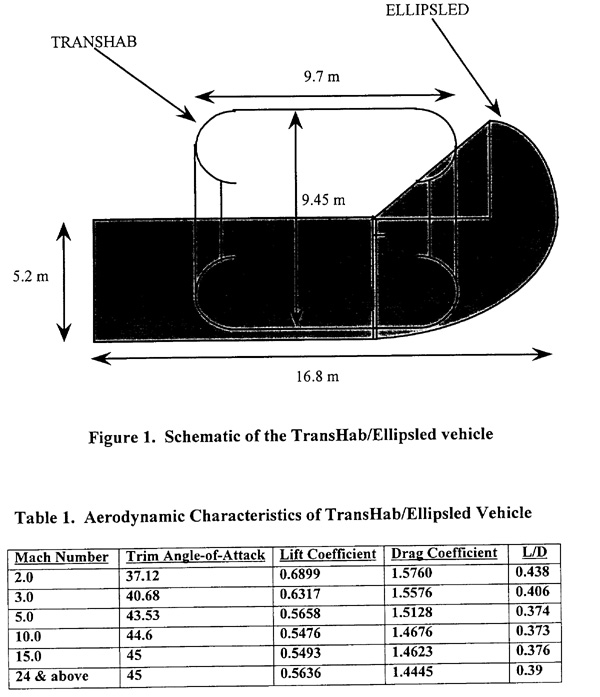
But the handsome propellant savings from aerocapture are so alluring that some NASA researchers did a study. This would be incredibly useful, especially if you want to reuse the spacecraft for several Mars missions or something. They came up with an aeroshell covering the impact side of the TransHab, dubbed the "Ellipsled" due to its shape.
The Ellipsled has a mass of 3929 kg, while the TransHab in the study was assumed to be 14,522 kg. They also assumed the rest of the vehicle had a mass of 7053 kg, presumably most of the propellant had been already burnt. Total of 25,500 kg. I am unsure from reading the report but I get the impression this represents the TransHab detaching from the rest of the spacecraft, carrying along only the ellipsled and a small rocket engine for change-of-plane maneuvers. Meaning the rest of the spacecraft goes sailing off into the wild black yonder as the TransHab aerocaptures into Terran orbit. The report mentions the TransHab being mated to a new spacecraft for a new Mars mission.
The thing has a lift-to-drag ratio of 0.39 at Mach 24 and above, which is better than the Apollo capsule's 0.3. So it is slightly more maneuverable. The deceleration limit is 5.0 g.
They were aiming for something that could approach Terra at the end of the Mars mission and aerocapture into a 420 kilometer orbit by burning off about 4.3 km/s of velocity. If one wanted to get fancy, it is much easier to brake into a high elliptical parking orbit with periapsis of 407 km and an apoapsis of 120,000 km. Yes it makes it more difficult to refurbuish and reequip the ship for a new mission, but it really cuts down on the required trans-Mars injection delta V.
Power System
Mass (kg)
Stowed Vol. (m3)
Quantity
Secondary Power
Fiber Li-Ion Battery
0.17
335
1
Battery Charge/Discharge Unit
0.09
50
3
Wiring
Main Bus Cable
0.84
7.5
3
Jumper Cables
0.42
4.5
24
Secondary Power Distribution Cables
0.0001
0.213
816
Wiring Harness Secondary Support Structure
3.80
91
1
Power Management and Distribution
Galaxy Inverter Boxes
0.04
28
3
Custom Built 400 Hz, 115 Vac RPC Box
0.04
20
12
Kilovac Relays
0.001
2
45
Unitron PS-95-448-1 400 Hz to 60 Hz Frequency Converter
0.04
21.4
9
Vikor AC/DC Rectifiers
0.0007
2
9
Total
18
505.2
The primary power system for the spacecraft is a pair of nuclear reactors on the other end of the boom. Since they are external to the habitat module, their mass and volume are not included here.
The secondary power system is internal to the module. It consists of three main subsystems:
Secondary Power
Wiring
Power Management and Distribution
These three subsystems can be further broken down to the component level as shown in the table to the right.
The assumption was made that the power entering the habitat would be 115 Vac, delivered at 400 Hz. A final assumption that was made was that the habitat would nominally use 15 kW of power. The final subsystem that needed to be sized for this habitat was the secondary power source. Upon analyzing the architecture and the type of primary power sources, a decision was made to supply 24 hours of emergency power to the habitat that will accommodate 50% of the nominal load (180 kW-h).
Avionics
Includes a communication system; a guidance, navigation and control system; a crew interface system; and
an integrated vehicle management system. It has a peak power consumption of 864 watts. It provides for the command, control, communications, and computation required for the carrying out the mission including insertion into transit orbits. This involves provisions for crew displays; data, voice, and video communications home base, other orbital assets, and EVA crewmembers; an integrated health management system for onboard and ground monitoring of all systems; and a full flight system capability for Guidance, Navigation, and Control. The flight system must also integrate requirements for data communication and computational support for remote commanding of the spacecraft during any uncrewed phase as well as ground commanding during crewed phases. The crew interface must be integrated with data communications and computational support for remote commanding of visiting vehicles.
Environmental Control and Life Support System
Air Management Subsystem
This system recycles the oxygen, plucking it out of the carbon dioxide molecules and returning it to the atmosphere to be breathed once again.
First the stale air is pumped through a 4-Bed Molecular Sieve (217.7 kg, 0.6 m3, 733.9 W). It initially removes the water from the air (and sends it to be added to the life support water supply), then it removes the carbon dioxide.
The carbon dioxide and some hydrogen (from a source to be explained shortly) are fed into a Sabatier Reactor (26 kg, 0.01 m3, 227.4 W). They react producing methane and water: CO2 + 4 H2 → CH4 + 2 H2O + energy.
The methane is vented into space. The water is fed into an electrolyser to be split into hydrogen and oxygen. Specifically a Solid Polymer Electrolysis (SPE) Oxygen Generation Subsystem (OGS) (501 kg, 2.36 m3, 2004 W).
The hydrogen is sent back to the Sabatier Reactor to take care of the next batch of carbon dioxide. The oxygen is added to the breathing mix and released into the habitat module's atmosphere.
The TransHab starts out with a tank of high pressure oxygen (20.4 kg, 0.78 m3, 6W, 30 MPa) and a tank of high pressure nitrogen (94.4 kg, 3.6 m3, 6W, 30 MPa). The oxygen tank has three days worth of breathing for six crew, enough to give the Sabatier Reactor time to get started. The nitrogen tank has enough to establish the proper ratio for the breathing mix, and some extra to compensate for any atmosphere leaking into space.
Water Management Subsystem
An aluminum potable water storage tank (145.9 kg, 0.54 m3, 5 W) initially contains a three day supply of water for the six crew members. Waste water is sent through a Vapor Phase Catalytic Ammonia Removal (VPCAR) system (1119 kg, 5.5 m3, 6090.7 W). The VPCAR process is a wastewater treatment technology that combines distillation with high-temperature catalytic oxidation of volatile impurities such as ammonia and organic compounds.
The report mentioned that the VPCAR system was selected over a rival system since it had a lower mass, volume, and turnaround time. The VPCAR's drawback was the larger power requirements.
Waste Management Subsystem
The Waste Management Subsystem uses a Warm Air Dryer (527.2 kg, 11.2 m3, 2,043.7 W). This dries out the crew's fecal matter, reclaiming the water. The dried residue is discarded.
Thermal Control System
Fluid mass (kg)
Dry mass (kg)
Volume (m3)
Power (kw)
Internal TCS
0.0
111.0
0.158
0.000
External TCS
34.4
131.0
0.129
1.109
Radiators
n/a
243.8
1.742
0.000
Total
34.4
485.8
2.0
1.1
520.2
The TCS system concept makes use of flexible lightweight body mounted radiators, which are attached to the outer surface. The TCS system has been sized to collect and reject 15.0 kW of heat. Mass, power, and volume are listed below. ITCS refers to coldplates, heat exchangers, and plumbing located inside Transhab, while ETCS refers to similar equipment mounted on the outside. Radiators are listed separately.
A propylene glycol/water coolant is circulated inside the module to collect heat from heat exchangers and coldplates and this heat is rejected to space through the body mounted radiators mounted on the outer shell of the module. Radiator size was determined for the warmest case (0.5 A.U. orbit). The results indicate a required area of 78 m2. This represents 51% of the available area of the cylindrical portion of the shell.
Two other sizing exercises were also conducted for the module. The first determined the radiator area needed to reject twice the average load of 15 kW. Assuming the warmest environment temperature at 0.5 A.U., the analysis indicated approximately 157 m2 was required. This is just slightly over the total cylindrical area of the shell of 153 m2, therefore rejecting just under 30 kw on average is the maximum amount of heat rejection possible without adding something like a heat pump to raise the radiator temperature.
Another sizing exercise determined the heat rejection given the following scenario: The module is in Mars orbit and the crew has left the module for the Martian surface leaving the AG module uninhabited. If the heat loads are reduced and the TCS fluid is allowed to approach its freezing temperature of -50°C, the question becomes how much heat can be rejected. The analysis indicated that the radiators could still reject up to 11 kW of heat with the TCS fluid just above its freezing temperature. This is in part due to the much colder environment at the low Mars orbit assumed. At the 0.5 A.U. orbit location heat rejection would be approximately zero because the radiator and sink temperature would be identical for this scenario.
Propylene glycol was selected for the working fluid. The relevant options are water or 60% propylene glycol with 40% water or some other working fluid. While water is non-toxic and has greatest thermal capacity per mass of working fluid, it also freezes at 273.2 K and thus may not allow sufficient radiator availability for some mission phases. 60% propylene glycol with 40% water is also non-toxic but, compared to water, it is a less desirable thermal working fluid. However, 60% propylene glycol with 40% water freezes at roughly 223 K, a significant advantage over water. Thus, tentatively the working fluid for the thermal control fluid loops is 60% propylene glycol with 40% water. As above, complete resolution of this issue also requires in-depth thermal environment modeling focusing on radiant rejection from the habitat.
Accommodations
This provide crew accommodations systems and layout to make an 18-month mission habitable for six
crewmembers. Functions covered include the following: crew support (meal preparation, eating, meal clean-up, full-body cleansing, hand/face cleansing, personal hygiene, human waste disposal, training, sleep, private recreation and leisure, small-group recreation and leisure, dressing/undressing, clothing maintenance), and operations (facilities for meetings and teleconferences, planning and scheduling, general housekeeping). It is also responsible for configuring work and personal stations such that traffic congestion are minimized. Work efficiency, space use, crew comfort, and convenience should be maximized.
EVA Systems
The EVA system is designed to be used for three planned, two person EVA days per mission. The airlock will transfer two crewmembers per cycle. If full crew transfer is required in LEO, this system assumes all three EVAs are used to transfer crew out of the habitat. EVA days are sized to be 8 hrs, and are accomplished with a personal life support system (PLSS) that is sized for eight hours. The system includes a single flexible airlock with umbilical support and PLSS recharge system; no gas reclamation is planned due to the minimal number of EVAs (3). Two EVA tools boxes are provided. Translation aids are provided to aid crew transportation about the vehicle. EVA system spares are also provided.
Included in the airlock arrangement is a single flexible airlock that allows two persons to egress the AGH at one time. A staging area by the inside airlock door is included in the concept. This area provides volume to store all space suits as well as space suit spares and expendables. Provisions for donning, suit expendables recharge, and checkout are included as well. An unpressurized area by the outside airlock doors is included in the concept. It provides a place for EVA tool storage and allows handling of large objects.
EVA tools provided consist of two toolboxes containing mechanical, electrical, and storage/tie downs. The tools are stowed in the unpressurized area just outside the airlock. EVA system spares as needed to support the six suits and airlock suit recharge provisions are stowed in the AGH in the EVA staging area and remain stored there until needed.
Structure and Mechanism
Element
Mass (kg)
Unpressurized End cone
650
Pressurized End cone
800
Internal fixed structure
2,120
Internal deployable structure
1,870
Outer Shell
6,000
Crew Quarters Radiation Insulation
1,500
Total
12940
The structure and shell are to provide a safe habitat for the crew and the necessary space to store supplies and equipment to sustain them for the duration of the entire mission. The inflatable module design was chosen because it is the best means to effectively increase the habitable volume of a spacecraft while keeping the diameter of the core within acceptable payload size limits set by current launch vehicles. The airlock system is to provide the crew with the capability to perform extravehicular activities. It is to be located atop the habitat module, so as to allow the fully suited EVA astronauts to take advantage of a slightly lower gravitational pull.
Medical Ops
The medical operation capabilities onboard the artificial gravity habitat during transit will provide medical contingencies to promote successful mission completion, crew health, safety, and optimal crew performance.
The potential medical contingencies that are to be addressed include those currently required for International Space Station and additional procedures unique to a continuously rotating spacecraft. Following the convention for classification of medical contingencies onboard ISS, the artificial gravy habitat will enable the practice of emergency medicine, environmental medicine, countermeasures or preventive medicine, rehabilitation, and dentistry. Emergency medical procedures will provide for Advanced Cardiac Life Support (ACLS), Basic Cardiac Life Support (BCLS), and trauma. Additionally, emergency medical contingencies may include shock, behavioral, compromised airway or breathing, drug overdose, and smoke inhalation. Environmental medicine will enable treatment for exposure to toxic and hazardous materials. Countermeasures/Preventive Medicine and Rehabilitation will enable countermeasures to prevent neurovestibular dysfunction resulting from the Coriolis effect induced by the rate of rotation of the spacecraft. Coriolis effects induced by rotation of the spacecraft develop within the neurovestibular system and impacts motor performance, behavior, and motion sickness. Exposure to partial gravity, 0.38G, may greatly impact musculoskeletal and cardiopulmonary systems. Dentistry onboard the artificial gravity habitat will enable basic cleaning, crown replacement and treatment of exposed pulp.
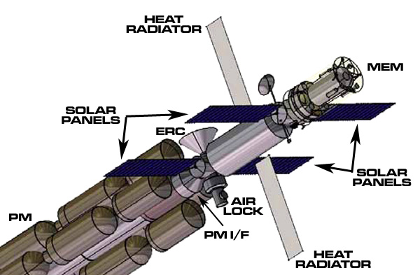
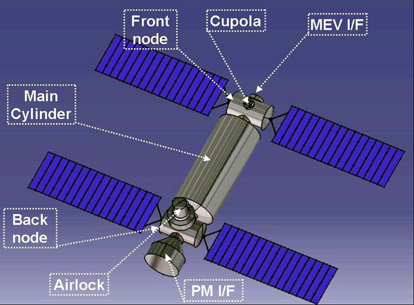
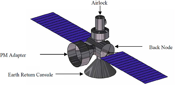
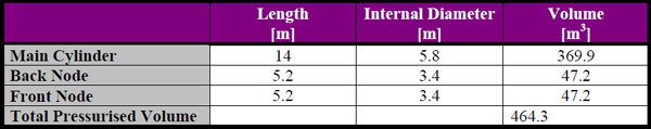
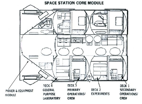
The habitat module is a cylinder where the explorers live. It has two nodes, one at each end, to attach to the rest of the spacecraft. Each node has an interface (I/F) module, the propulsion module pluging into the PM I/F and the Mars excursion vehicle pluging into the MEV I/F.
The "back" node has an airlock (and spare docking port) and the Earth reentry capsule. It also has an EVA prep area (including three space suits), a toilet, and what passes for a shower (a "hygiene area"). For conceptual purposes the design is using an airlock straight off the International Space Station.
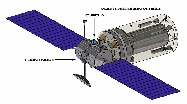
The "front" node has storage, a recreation area, a spare docking port, and the command area complete with a cupola. It also has the communication antennas. The cupola is kind of worthless but is included for psychological reasons (crew going bat-crap insane being cooped up in a tin can with no windows).
Each node has two solar power units, for a total of four. Each unit has a movable solar cell array and a storage battery.
The two nodes and the main cylinder can be sealed off from each other in the event one part springs a leak and depressurizes. If the main cylinder depressurises, the crew has to be evacuated to the front or back node for a couple of days until the leakage has been repaired.
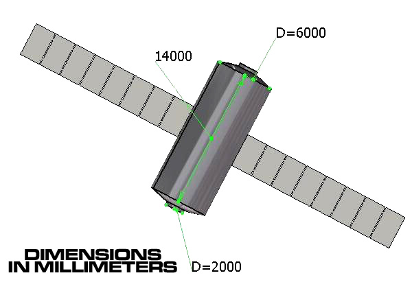
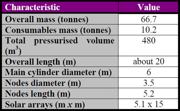
The total habitable volume has a minimum of 450 m3; where 1/3 of the volume is used for
storage, and the remaining 2/3 are the habitable volume. About 5% of the total volume has to be
considered for the module structure.
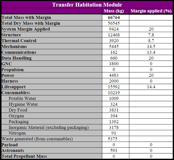
It carries enough consumables for six people to last for 963 days (5,778 person-days).
The habitat module has 9 gm/cm2 of radiation shielding to stop enough galactic cosmic radiation to keep the astronauts under the yearly and career doses of radiation. The storm cellar has 25 gm/cm2 to protect the astronauts from solar proton storms.
The designers looked into adding a spinning habitat to help prevent the dire effects of prolonged free fall on the crew, but concluded it just had too much penalty mass. Instead the crew will just have to do daily exercise in a little one-person centrifuge.
Main cylinder with heat radiators
Back node with Propulsion Module adaptor, and twin solar power plants
Front node with Mars Excursion Module adaptor, and twin solar power plants
Habitat properties
Habitat mass budget
Dimension of habitat components
The various areas inside the habitat are classifed by "zone":
PRIVIATE ZONE: Areas where the crew is always alone. Crew quarters
PERSONAL/UTILITY ZONE: Areas where the crew works/trains mostly on their own. Command, laboratory, exercise, toilet, hygiene, medical
SOCIAL/COMMUNAL ZONE: Areas where the crew is mostly with other crewmembers. Food preparation, eating, conferences, video
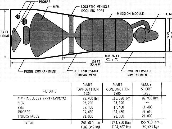
The MEM is the Mars Excursion Module (Mars Lander), a standard North American Rockwell MEM
The EEM is the Earth Entry Module, which lands the crew on Earth at the end of the mission
The MM is the Mission Module, which is the habitat module, the focus of this webpage section
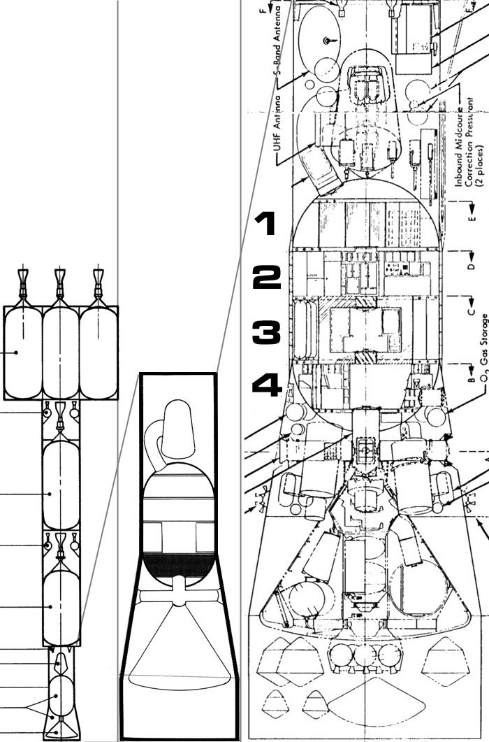
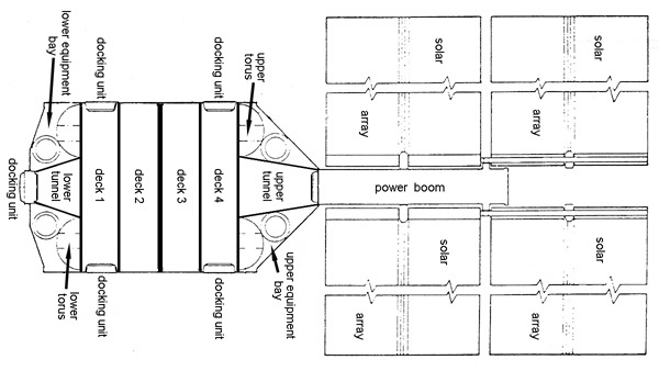
click for larger image
Left: over-all space vehicle view
Middle: Zoom in on payload module ("spacecraft")
Right: Zoom in with decks labeled
In the Boeing report they call the payload module the "spacecraft", the string of five engine modules is the "space acceleration system", and the entire thing is the "space vehicle"
CREW COMPARTMENT
The crew compartment provides a pressurized shirt-
sleeve environment for the crew and storage for equipment which needs a
thermal or pressure environment or is expected to require maintenance. Atmosphere
within the crew compartment is nominally 7 psia (48kPa) O2/N2, 70°F and 50%
relative humidity. The crew compartment consists of a 17.8-foot (5.4m)
cylinder, 22 feet (6.7m) in diameter (decks 2 &3), joined at both ends by hemispherical
bulkheads (decks 1 & 4). A meteoroid bumper surrounds the cylindrical section of the
crew compartment (decks 2 &3). Overall length of the crew compartment is 39.8 feet (12.1m)
which provides a total volume of approximately 12,250 cubic feet (347m3). Total
pressurized volume within the crew compartment is estimated to be 10,000
cubic feet (283m3) for 500-day class missions with the free volume (major areas
unoccupied by equipment) 5400 cubic feet (153m3) or 900 cubic feet (25.5m3) per man (which is ample). A
surface area of approximately 1200 square feet (112m2) is provided by the
cylindrical portion of the crew compartment.
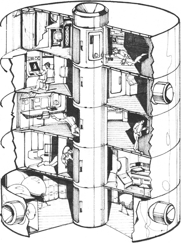
The internal arrangement of the crew compartment results from having to
contain within the selected 22-foot (6.7m) diameter pressure compartment a
floor area requirement of approximately 1400 square feet (130m2) and ceiling
height of 7 feet (2.1m) in order to provide sufficient volume for equipment
and men. As a result, the crew compartment consists of four separate
levels of activity. Each level is designed to include those crew
operations or equipment operations of a similar nature. The levels have
also been located to minimize the interface or distance between levels
of similar activities. An example is the above/below arrangement of the
two levels which include all areas and equipment associated with spacecraft operations and crew living quarters. Equipment and cabinets
within the crew compartment and located near the walls are attached in
place and do not have provisions for removing or hinging the entire
cabinet to expose walls for puncture repair caused by meteoroids.
Previous inhouse studies such as Manned Orbital Laboratory have indicated a greater reliability benefit can be achieved by using a weight
equal to the hinging mechanisms in the meteoroid shield itself.
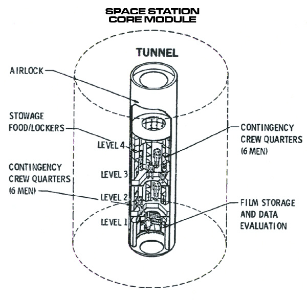
Deck 1
MM-EEM Tunnel Hatch is the hatch for the crawlway connecting the habitat (MM or mission module) with the home reentry vehicle (EEM or Earth Entry Module)
click for larger image
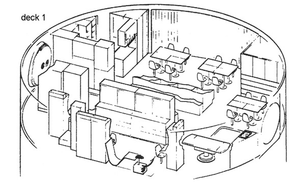
DECK 1
Activities of a relatively quiet nature are located on Deck l. In general, this deck includes the sleeping
quarters, dispensary, and personal care facilities. Each crewman is
provided with a separate room to be used for sleeping and stowage of
personal hygiene supplies such as clothes, cleaning pads, and personal
care items. Cabinet space is also available for other equipment associated with the mission module. The rooms also provide solitude for
crewmen if desired, and allow a crewman to be isolated should the need
exist. Approximately 110 cubic feet (3.1m3) of free volume is provided per
room. Included within the dispensary is the necessary equipment for
crew psychological/physiological monitoring, medical/dental equipment
and supplies, and physical conditioning equipment for the cardiovascular
system and musculoskeletal system of the body. Personal care facilities
include a zero-g shower and waste management system (toilet). Adjacent
to the waste management system is the urine water recovery unit. After
processing, this water is transferred to holding tanks on Deck 2.
Located in the upper portion of Deck l is a pressure hatch leading to
the EEM (Earth Entry Module, reentry vehicle) transfer tunnel. A centrally located, 36 inch (0.91m) diameter hatch
leads to Deck 2.
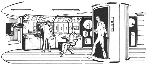
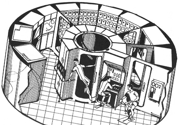
Activities of a relative high intensity are located on Deck 2. In general, the activities include the
command/control center, combination food storage/preparation area, and
recreation area. The command/control center includes the necessary
displays and controls to monitor and control all subsystem operation,
environment parameters, and vehicle operations such as attitude changes,
rendezvous, and dockings. The control center is occupied at all times.
The food storage/preparation area includes freezer, hot water provisions,
and food storage cabinets for missions greater than 500 days. Dining
facilities are also included in the area. Another section of this area
contains the remainder of the water management system consisting of the
wash water/condensate water recovery unit and a 2-day water supply.
Water for crew consumption comes to this supply from the makeup water
supply located on the third deck. Storage for wash pads occupy the
final bay in this area. The remainder of Deck 2 is used for recreation,
conference room, and storage for spares (redundancy). Dividing the
recreation area and food storage/preparation area is a bay for electronic
equipment with the most significant being the control moment gyros (CMG) of
the attitude control subsystem. Located in the center of the floor of
this level is the pressure hatch leading to the radiation shelter on
Deck 3. Also located in the floor are nonpressure hatches which allow
access to the equipment bays of Deck 3.
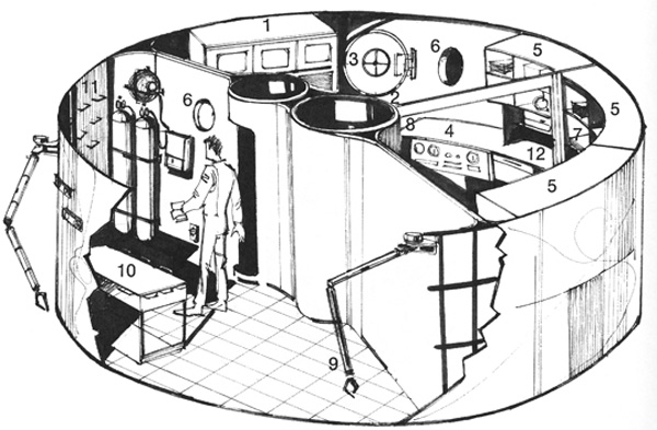
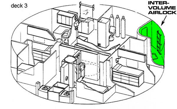
The major features of the third deck are the combination
radiation shelter/emergency pressure compartment and equipment bay. Height of this deck is approximately 10 feet (3.1m) rather
than 7 feet (2.1m) as for the other decks due to the design feature of the
radiation shelter. The radiation shelter consists of an inner compartment 10 feet (3.1m) in diameter and 7 feet (2.1m) high which also serves as the
emergency pressure compartment should the remainder of the crew compartment become uninhabitable for short periods of time. A total volume of
600 cubic feet (17.0m3) is provided by the radiation shelter with approximately
60 cubic feet (1.7m3) of free volume available per crewman. The shelter also
provides quarters for the crew during periods of high radiation. These
periods include passing through the Van Allen belt anomaly while in
Earth orbit; during the firing of each nuclear propulsion module,
particularly during departure from Earth as the space vehicle may pass
through the heart of the Van Allen belt, and the firing of PM-3 (the nuclear engine module directly adjacent to the crew quarters) when a
minimum of hydrogen is between the crew and Nerva engine; and during
major solar flares which may last up to 4 days. Because the shelter
may be occupied for extended periods of time and during nuclear propulsion firings, it is necessarily provided with sufficient displays
and controls to enable the crew to continue space vehicle operations.
A 4-day emergency food, water, and personal hygiene supply is provided
within the shelter as well as separate atmosphere supply and atmosphere
control loops. Each crewman is provided with a storage compartment,
which contains his pressure and emergency provisions. Should the
crew compartment become uninhabitable, all crewmen transfer to the
shelter and don pressure suits. A repair team can then be sent out to
correct the malfunction. The final item housed in the shelter is the
photographic film used in the experiment program. This location has
been selected as it provides the maximum amount of radiation shielding
at no additional weight penalty.
The bulk of the radiation protection for the shelter is provided by a
20 inch (0.5m) thick combination food/waste storage compartment. This storage
compartment contains the initial 500-day supply of food and surrounds
the entire shelter providing approximately 26 lb/ft2(137kg/m2) of shielding.
Further discussion of the radiation protection analysis is presented in
Section 4.2.1.4. Food stored around the walls of the shelter is reached
from the equipment bay. Floor panels are removed in the second deck to
reach the food above the shelter, while ceiling panels of the fourth
deck are removed to reach the food located beneath the shelter. As food
is removed, the vacated area is filled with waste matter in order to
maintain a nearly constant mass.
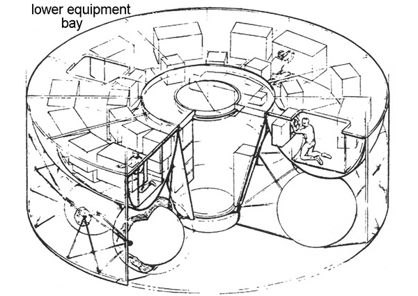
The equipment bay of this deck includes a storage area extending 2 feet (0.6m)
inward from the outside wall and around the entire periphery. A passageway is provided between the equipment and the food storage compartment
of the radiation shelter. The passageway is between 24 to 30 inches (0.6m to 0.8m)
wide which should provide sufficient space for maintenance operations
or removal of supplies even while operating in a pressure suit. Housed
in the storage area are three 24 inch (0.6m) diameter water containers and
positions for three other containers to be used for missions between
500 to 1000 days. Also included in the area is the major portion of the
environmental control system equipment such as electrolysis unit, Bosch
reactor and atmosphere control units, storage for spares and provisions
for food, and spares storage for missions beyond 500 days.
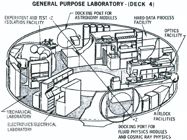
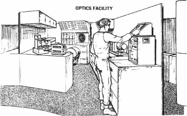
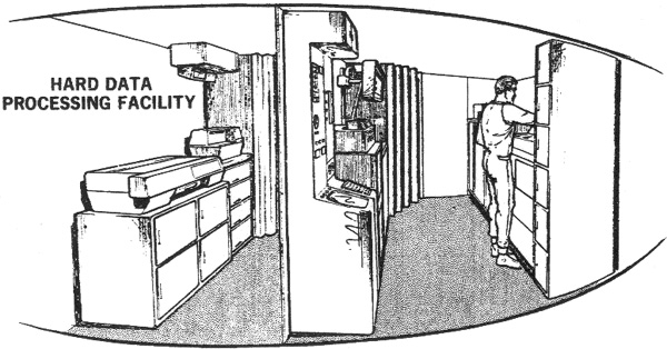
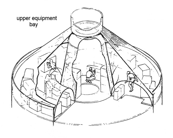
The fourth deck of the crew compartment is comprised almost
entirely of laboratories associated with the experiment program. These labs contain the necessary equipment
to perform certain experiments, control the operation of all experiments,
and process and store all experiment data. To accomplish these functions
most effectively, the deck is divided into five separate labs. These
include labs for optics, geophysics, electronics, bioscience, and
science information center. Further discussion of these labs is
presented in Section 4.2.2. Extending from the optics lab is a small
30-inch diameter airlock used to retrieve the mapping camera for film
changing and maintenance.
Located centrally and in the ceiling is a pressure hatch leading to the
combination radiation shelter/emergency pressure compartment. Also
located centrally but in the floor is the pressure hatch leading to the
airlock used for crew transfer to the MEM, logistics vehicles, or extra-
vehicular activity operations. Beneath the floor of this deck and near
the aft exit are located the automatic maneuvering units used for extra-
vehicular activity (EVA) operations. Propellant for these units is
replenished prior to entry into the crew compartment while oxygen and
other expendables are replenished after entry.
With the habitat modules, certain assumptions have been made.
Habitat modules are composed out of one or more cylindrical ("barrel") units with end domes.
If the habitat is composed of multiple units, all units are the same length.
End domes have one of the following aspect ratios: 10:1, 5:1, 3:1, 2:1, r2:1. (ratio of dome radius to dome height)
Barrels have one of the following diameters: 4.4m (small), 7.6m (medium), or 10m (large).
All hatches, windows, and connecting tunnels are on the barrels, not on the end domes.
On each level the ceiling is 2.3 meters above the floor.
The floors are 0.5 meters thick.
Aspect ratio is ratio of end dome radius to end dome height.
Here radius is 3.8m and height is 1.9m so aspect ratio is 2:1
The specifications of a given habitat unit are given by a cryptic notation:
Barrel diameter is 4.4m (small), 7.6m (medium), or 10m (large). Gravity is microgravity (μ) or 1 Terran gravity (g). End dome aspect ratio is ratio of end dome radius to end dome height. Barrel orientation is vertically stacked like a skycraper (H) or horizontal like a tunnel (L).
Oddly it does not specify the length of each cylindrical unit, presumably that can be calculated from the other values. Probably there is a specified minimum volume for a given number of crew.
There are lots of possible combinations. They were narrowed down to the following handfull, by considering lots of factors in boring detail that you can read all about in the report. Mass values without question mark are from the report. Values with a question I attempted to determine graphically from the fuzzy chart below, use at your own risk.
Spoiler alert: they went with 6Mg2-L.
Configurations of Interest
Config
Crew
Module Dia (m)
Grav
Dome Ratio
Num Modules
Topology
Orient
Mass (kg)
4Sg2-2/1
4
4.4
1g
2:1
2
tunnel
8,849
4Lg3-H
4
10
1g
3:1
1
n/a
stacked
14,500?
6Mg2-L
6
7.6
1g
2:1
1
n/a
tunnel
12,500?
6gMg3-H
6
7.6
1g
3:1
1
n/a
stacked
10,746
8Sg2-3/2
8
4.4
1g
2:1
3
tunnel
17,500?
8gM3-H
8
7.6
1g
3:1
1
n/a
stacked
11,694
8Lg3-H
8
10
1g
3:1
1
n/a
stacked
17,500?
10gM3-H
10
7.6
1g
3:1
1
n/a
stacked
13,591
12Sg2-4/5
12
4.4
1g
2:1
4
tunnel
27,500?
12gM3-H
12
7.6
1g
3:1
1
n/a
stacked
14,538
12Lg3-H
12
10
1g
3:1
1
n/a
stacked
20,000?
Annoyingly, the report did not give the equations for calculating the mass of the habitat hull and framework. All they gave is the following fuzzy graph.
Values with four non-zero figures or more are from the sample table below. Values with less I tried to determine graphically from the fuzzy image, use at your own risk. click for larger image
ESTIMATING HABITAT EQUIPMENT MASS
Relevant to our interests is the "parametric mass estimating algorithms" i.e., magic equations that calculate how heavy the equipment is. If you are a science fiction author or game designer, these are a big help.
F ≡ food freezer mass (kg)
N ≡ number of crew
E ≡ number of Environmental Control And Life Support System (ECLSS) strings (total main and back-ups)
M ≡ volume (units of Space Station Freedom module volumes)
Floor & wall coverings, hardware allowance for access doors
Power dist. & control sys.
17 * P
Lighting
73 * M
External hatches and bulkheads
692
Combining all the above into one uber-equation:
TotalMassEquipment = 2,724 + (1,909 * E) + (1.919 * N) + F + (1,633 * M) + (1.43 * Ap) + (14.3 * Af) + (17 * P) + (10 * N * M)
Here are some sample masses.
"Pressure Vessel" includes module, bulkhead, hatches, and ECLSS equipment. Hull configuration is specified. Apparently they used the lowest mass configuration for each crew size.
"Crew Consumables & and Spares" includes food, water, crew & effects, ECLSS consumables, & spares. "Outfitting Equipment" is as per the above formula.
Sample Module Masses
Crew Size
Mass (kg)
4 Crew
44,260
4Sg2-2/1 Pressure Vessel
8,849
Crew Consumables & Spares
10,700
Outfitting Equipment
24,711
6 Crew
59,256
6gMg3-H Pressure Vessel
10,746
Crew Consumables & Spares
16,050
Outfitting Equipment
32,460
8 Crew
72,089
8gM3-H Pressure Vessel
11,694
Crew Consumables & Spares
21,400
Outfitting Equipment
38,995
10 Crew
87,456
10gM3-H Pressure Vessel
13,591
Crew Consumables & Spares
26,750
Outfitting Equipment
47,115
12 Crew
99,880
12gM3-H Pressure Vessel
14,538
Crew Consumables & Spares
32,100
Outfitting Equipment
53,242
PRELIMINARY NODE MAP
Scaled Proximity Diagram
This was a rough draft of the connectivity of the habitat module. It was used as a jumping-point, and was radically refined (see below).
For a crew of four. Values in {curly braces} indicate areas not drawn on the map.
Representative Allocations (referenced as floor area for gravity configuation)
Activity Location
Area (m2)
Crew Quarters
16
Hygiene/Waste Mgt
3
Galley/Storm Shelter
16
Wardroom/Recreation
12
Exercise
2
Greenhouse
6
Operations Station (control room)
2 (per crew)
Workstations
8
Science Equipment
10
Crew Health Center
7
Laundry
1 (per crew)
{ECLSS}
{12}
{EVA Stowage}
{2}
{Spares Stowage}
{7 (15% active equipment)}
{Circulation}
{9 (15% crew space)}
Rough draft of a 4-crew habitat module click for larger image
This is two rough drafts of 4-crew habitat modules.
Module on the left is 4Sg2-2/1, which the report will tell you means four crew, small diameter of 4.4m, assumes 1g, has a end dome aspect ratio of 2:1, and consists of two habitable sections resting on their side like tunnels, and the sections are lying adjacent side-by-side. Note how ECLSS is under the floor.
Module in the right is 4Lg3-h which means four crew, large diameter of 10m, assumes 1 g, end dome ratio of 3:1, and has a single habitable section oriented vertically like a sliced bologna, with two floors.
Rough draft of an 8-crew habitat module click for larger image
This is a rough draft of an 8-crew habitat module. It is 8Sg2-3/2 which means eight crew, small diameter of 4.4m, assumes 1g, has an end dome aspect ratio of 2:1, and consists of three habitable sections resting on their sides like tunnels, two side-by-side and one above.
Rough draft of an 8-crew habitat module click for larger image
This is a rough draft of an 8-crew habitat module. It is 8Lg3-H which means eight crew, large diameter of 10m, assumes 1g, has an end dome aspect ratio of 3:1, and has a single habitable section oriented vertically like a sliced bologna, with four floors.
Rough draft of an 12-crew habitat module click for larger image
This is a rough draft of a 12-crew habitat module. It is 12Sg2-4/5 which means twelve crew, small diameter of 4.4m, assumes 1g, has an end dome aspect ratio of 2:1, and consists of four habitable sections resting on their sides like tunnels, two side-by-side, one above and one below.
click for larger image
This is a rough draft of a 12-crew habitat module. It is 12Lg3-H which means twelve crew, large diameter of 10m, assumes 1g, has an end dome aspect ratio of 3:1, and has a single habitable section oriented vertically like a sliced bologna, with six floors.
6 crew configuration 6Mg2-l I made this image to replace the utterly worthless blurry mess that is in the original report. "Original is of poor quality" indeed!
Scale man is 1.72 meters tall
Upper Deck
each square is one square meter
no, I can't make out the writing in the gray areas, sorry click for larger image
Lower Deck
each square is one square meter click for larger image
After some optimizing, they focused on a 6-crew habitat module. It is 6Mg2-l which means six crew, medium diameter of 7.6m, assumes 1g, has an end dome aspect ratio of 2:1, and has a single habitable section resting on its side like a tunnel.
It has a cross-sectional bisecting bulkhead and a dihedral-tension-tie deep floor.
EVOLVED NODE MAP
Scaled Proximity Diagram
This is the evolved design for the Mars mission habitat module. The "Area" values assume 1g conditions. Assumes a crew of six.
Area / Volume Allocations
Function
Area (m2)
Volume (m3)
Crew Cabins (for 6)
31.2
71.1
Laundry
1.5
3.4
x2 Hygiene/Waste Mgt
4.7
10.7
Crew Health Care
6.5
14.8
Science Equipment
14.0
31.9
EVA Equipment
8.0
18.2
Workstations (for 4)
12.0
27.4
Recreation/Exercise
20.0
45.6
Operations (control room)
6.0
13.7
Wardroom
18.0
41.0
Galley
18.5
42.1
Greenhouse
26.0
59.3
{Circulation}
32.0
73.0
TOTAL
198.4
452.2
Studies of architectural design
Note closet is on fore wall on opposite side of the desk
from MTV Habitat Module Layout - Lower Deck
Note closet is on aft wall adjacent to desk
Studies of architectural design
Studies of the internal supporting structure click for larger image
CADD study of internal supporting structure click for larger image
click for larger image
click for larger image
Blue Max Habitat
These are hab module sections created by Ray McVay for his Black Desert universe.
RECREATION ROOM
Even the most cramped spacecraft or stations must accommodate their crews to a certain degree. Here we see Node 5, a general crew space where most of the exercise equipment is kept. Certain homey touches, such as photographs on the door to the head, make the space more pleasant, but even here the necessities of life in orbit take priority. At any time, new experimental systems or laboratory pallets may be installed, turning the "Rec Room" into a more utilitarian compartment.
A pair of sat-phones are clipped near each hatch in case of intercom failure.
Free fall ping-pong is not for amateurs.
Wind chimes let astronauts know if the ventilation is working — even in total darkness.
Astronaut keeps fit and helps fight against bone and muscle loss.
The Rec Room houses an ultimate luxury in space: a zero-gee shower.
Refreshing orange beverage floats where astronaut left it, ready to provide another sip.
Exercycle left unstowed for next user.
A loose latch has left the cooler door open, allowing saved chocolate drink to escape.
Multiple hand rails are needed to move around in free fall.
All nodes equipped with basic first-aid and damage control lockers.
Net Habitable Volume Number Charge. In the spring of 2013, the NASA Human Research Program (HRP)
charged the Behavioral Health and Performance (BHP) Element with the task of defining a minimum net
habitable volume (NHV)—that is, a minimum number of cubic meters/feet – needed to support crews
for exploration missions. Such missions involve travel at greater distances, beyond low‐Earth orbit, and
could consist of longer durations (up to 2.5 years, or approximately 912 days) than current 6‐month
International Space Station (ISS) missions.
Subject Matter Experts Consensus Session. Toward this goal, a NASA‐based NHV Team consisting of
representatives from several HRP Elements (Behavioral Health and Performance, Space Human Factors
and Habitability, Exploration Medical Capability) and Exploration Habitation, planned and implemented
an evidence‐based consensus session with a selected group of subject matter experts (SMEs), to derive a
minimum acceptable NHV number for a Mars mission. The session included a panel of 5 external SMEs
with relevant backgrounds in psychology (behavioral, cognitive, and environmental), architecture, and
industrial ergonomics. A detailed list of the participants can be found in Appendix 1. The SME consensus
session was held January 22 and 23, 2014 at the NASA Johnson Space Center, with 2 of the 5 SMEs
participating virtually.
Considerations. Before deliberations, representatives from the NASA‐based NHV Team provided
background materials to the SMEs and discussed relevant items to assist in deriving the minimum
acceptable NHV. These items were:
Definition of Net Habitable Volume: The definition of functional volume is “the volume left
available to the crew after accounting for the loss of volume due to deployed equipment,
stowage, trash, and any other structural inefficiencies and gaps (nooks and crannies) that
decrease the functional volume” (HIDH, 2010).
Definition of Minimum Acceptable Net Habitable Volume: For the purpose of the consensus
session, a definition for Minimum Acceptable NHV, was established: “the minimum volume of a
habitat that is required to assure mission success during exploration‐type space missions with
prolonged periods of confinement and isolation in a harsh environment. This definition
acknowledges that, in theory, smaller volumes are possible; however, these would be
unacceptable from human factors and behavioral health perspectives with likely negative
consequences for psychosocial well‐being and performance of the crew and thus mission
success. The minimum acceptable NHV depends on multiple parameters, including crew size,
mission duration, and functional‐task requirements – while considering the volume required for
crew to perform necessary tasks and maintain psychological and behavioral well‐being. In this
instance, considerations in defining minimal acceptable volume included volume requirements
for relevant task envelopes, as well as volume‐related requirements associated with maintaining
psychological and behavioral health over extended durations (for example, 1 to 2.5‐year
missions), while living and working in an isolated, confined spacecraft environment in deep
space.”
Exploration Mission Parameters. For the purpose of defining a minimum acceptable NHV
number and associated caveats, mission parameters based on the NASA Mars Design Reference
Architecture 5.0 (Drake, 2009), were defined. Panelists and NASA representatives were asked to
determine a minimum acceptable NHV number for a mission that provided the following
characteristics:
Presumably some combination of US, Russia, Europe, Canada and Japan
Mission Tempo
Long periods of low mission tempo, interspersed with high activity times (for example, launch, jettison tanks, dock, landing)
Communication Delays
Up to 22 minutes one‐way with blackout periods
Autonomy from Ground
Increasing en route to Mars, decreasing during return to Earth
Consensus Session Objectives. The 5 SMEs were asked to provide inputs to the following objectives of
the NHV consensus session:
Provide a minimal acceptable NHV number based on the best available evidence from your field and spaceflight constraints given to you by NASA
Define the dependencies of the number based on caveats and countermeasure scenarios
Determine how minimal acceptable NHV volume changes with duration
Minimum Acceptable Net Habitable Volume
Based on the characteristics and parameters of the exploration class mission defined in Mars DRM 5.0
(Drake, 2009), the SMEs, with concurrence of the NASA representatives, recommended a minimum
acceptable NHV of 25 m3 per person.
Approach: The recommended minimal acceptable volume was derived through a series of steps, starting
with the identification of tasks (hygiene, exercise) that are expected to occur on a long‐duration mission.
Based on prior work conducted by the NASA Space Human Factors and Habitability Element, the
minimum volume needed for conducting such tasks was identified (Human Integration Design
Handbook, 2010, http://ston.jsc.nasa.gov/collections/trs/_techrep/SP‐2010‐3407.pdf).
Discussions were held regarding the co‐location of relevant tasks; for example, the ability to conduct
medical evaluations in the private crew quarters. While such an effort to identify specific overlaps had
been previously accomplished (Thaxton, Chen, & Whitmore, 2013), the current effort entailed ‘grouping’
like‐tasks into functional areas and then using specific task‐based volume numbers to determine the
volume needed for that multi‐functional area. Hence, the key functions of a crew on a Mars mission
were mapped to physical locations needed on a vehicle.
Overall, 7 functional areas were identified:
Berthing, or sleeping space/private quarters
Dining and communal activities
Work space
Exercise (area can also accommodate EVA suit donning and medical care)
Hygiene
Translation portals or pass‐throughs
Stowage access
Caveats. The minimum acceptable NHV recommendation is based on the following caveats (additional
caveats specific to each functional area are listed in the subsequent section):
Careful consideration was given towards determining the needed volume to support each functional area and the relative location of these functional areas. Thus, the recommended overall minimal volume should only be considered “acceptable” in the context of these design and volume requirements specific to each area, and the overall minimal volume therefore may no longer be acceptable if volume were to be subtracted from one functional area to enhance the volume of another
A microgravity environment that allows use of all of the volume
A separate radiation shelter is not accounted for within the defined minimum acceptable NHV number because it is assumed the crew habitat vehicle will offer appropriate radiation shielding
The proposed volume takes into account suit donning and doffing for EVAs, but additional volume may be needed to adequately address other EVA requirements (air lock). If so, the definition of this requirement will occur at another time
Assumes crew of 6; if crew number decreases, the volume per crewmember may increase as the relationship between crew size and acceptable volume requirements for areas such as dining and communal, exercise, and hygiene is not assumed to be linear
A larger volume for crew quarters than has existed in past spaceflight missions, to provide privacy and restoration that will be needed in the long‐duration exploration mission owing to the increased period of isolation and confinement
Point‐of‐use stowage is included in all areas
Rational layout of areas to allow for a separation of quiet and loud activities, as well as clean and dirty activities
Acoustic isolation and privacy between disparate activities/spaces
Within the spaces, acoustics are provided at appropriate levels and sound attenuation built‐in
Ability for crew to optimize aesthetics and personal control over environment (for example, allowing for flexible lighting and other aspects of the environment to be modifiable and flexible), and functional configuration so areas are ergonomic and rational
Assumes adequate sensory stimulation related to touch, sounds, smells, and vision
The proposed habitat that meets the defined minimum acceptable NHV number and the locations of the
7 functional areas are shown in Figures 1 and 2 below. (The architectural sketches were developed by
Hugh Broughton Architects, one of the SMEs.)
click for larger image
click for larger image
Caveats Specific to Functional Areas. The following caveats apply to specific functional areas as
identified below.
Berthing, or sleeping space private, crew quarters (Areas 1 and 2 in Figure 2)
Individual private quarters are to be provided for each crewmember
The volume for each individual crew quarters is 5.4 m3
These have been sized to allow crewmembers individual personal space for sleep, selfcare
(hygiene), and recreation, also acknowledging that adequate personal space
becomes even more important in missions of such unprecedented duration (Simon,
Whitmire, & Otto, 2012)
ISS crew quarters are, by comparison, 2.1 m3. The size of individual quarters also
allows for temporary isolation of a sick crewmember
Quarters are clustered together to provide for alternative social space
Allows for acoustic and vibration isolation from the remainder of the vehicle
Acoustic isolation to protect sleep and private communication
Can allow space for medical care (as can the Exercise area)
Multi‐purpose access space (Area 1 in Figure 2) allows for simultaneous crewmember access to
crew quarters as well as suited egress through that area
Quarters can be personalized (e.g. hanging pictures, varying positioning of bedding)
Dining and Communal Activities (Areas 3 and 10 in Figure 1, Area 4 in Figure 2)
Minimal volume assumes sufficiently large space to simultaneously fit all 6 crewmembers, so
that all 6 can dine together, as well as sit together to view video or participate in a team event
Flexible space to allow for both dining and communal activity
Differing orientations achieved in microgravity supports multiple tasks
Includes a window with a portal (~ 0.5 m3) as a way to visually extend the social space
and provide an important countermeasure for psychological health
Includes space/functionality and flexibility for a large screen (that may be comprised of smaller
screens tiled together and may be removable rather than permanent) to be used for virtual
window views, training/planning purposes, and screen‐based recreation
Includes sufficient space that is readily accessible for food preparation and storage
Includes a minimal plant growth chamber that will provide countermeasure support for
psychological health while providing multi‐sensory stimulation
Stowage access and access to window serves as form of definition/divider between areas of
different activity without impeding sense of volume
Table flexibility (e.g., can be stowed) to allow for increased space as needed
Stowage (Area 3 in Figure 2) and Stowage Access (Area 8 in Figure 1 and 2)
Logistics are assumed to be stored outside of the habitable area to provide additional radiation
protection
Size and volume driven by optimizing efficiency related to accessing stowed materials
Location is utilized to improve acoustic isolation
Stowage at two locations to improve accessibility and minimize crew time (between
berthing and galley, and between galley and the workspace)
Workspace (Area 6 in Figure 2)
Sized to allow up to 4 crewmembers to focus on meaningful work or activities simultaneously
Separated from the Dining and Communal Area to avoid cross‐contamination
Design of area is task‐driven
Exercise (Area 1 in Figure 1)
Allows for 2 exercise devices to be used concurrently
Assumes exercise equipment will be smaller than what is currently being used on ISS
Assumes medical activities can occupy the same space with a pause on exercise equipment during that period
Separated from dining area
Equipment can be stowed and portable
If possible, redundancy of exercise equipment – parts can be shared between exercise devices
Includes window with viewing area to support mission activities when external views are required and offer an important psychological countermeasure
Hygiene (Area 7 in Figure 1)
Provide volume for at least 2 separated hygiene and waste compartment areas
Located away from berthing and galley for privacy and olfactory separation, although distance from sleeping quarters (particularly at night) should be considered
Assumes some self‐care/hygiene tasks can also be completed in crew quarters
Translation Portals, or Pass‐through
Function‐thin partitions for visual and acoustic separation
Assumes additional volumes for pass‐throughs and transition paths
Adequately sized for a suited crewmember
Mission Duration. The third objective of the SME consensus session sought to characterize how minimal
acceptable NHV changes with mission duration. The consensus recommendation was: Given that the
volume is defined by the functions required of the mission, reducing the volume to accommodate a
shorter mission is not recommended. The proposed volume of 25 m3 is consistent with
previously proposed volumes (Table 1), while remaining significantly smaller than Salyut, the ISS, and
Space Lab. The only potential areas where volume could technically be reduced included the individual
crew quarters and the work area; a key mitigation in future spaceflight habitats; however, particularly
habitats supporting long‐duration missions, is the preservation of the volume of the berthing/crew
quarters, and the volume of the dining and communal areas. There may be technological advances
(smaller exercise devices) in the future that allow for slight reductions in work, hygiene, and exercise
space, but these remain to be developed and tested. Additional consideration is that EVAs may require
increased volume with the addition of a specific airlock.
As a result, the panel concluded that unless functional requirements change, the volume will not reduce
substantially.
Table 1 – Summary Habitable Volumes of Historical Long‐Duration Missions and Proposed NHV for
Future Exploration Vehicle
Long Duration Mission
Hab Volume (m3/person)
Maximum Mission Duration
Skylab
120.33
84 days
ISS
85.17
196 days
Salyut
33.5
237 days
Mir
45
438 days
Proposed NHV
25
912 days
Forward Plan for Research and Validation. Follow‐on work within the NASA team includes the ongoing
development and modification of an integrated research plan (IRP) that outlines specific steps needed to
test and validate relevant outcomes (for example, performance, behavioral health, physiological health,
privacy, team interactions) within the proposed minimum acceptable NHV number. Additional
assessments are needed to evaluate the minimum acceptable NHV number and various design
configurations that incorporate behavioral health countermeasures anticipated for exploration class
missions. The IRP further defines efforts for testing habitability‐related countermeasure effectiveness
(virtual worlds, immersive environments). In addition to the ISS, various high‐fidelity analogs (Human
Exploration Research Analog [HERA], the Russian Institute for Biomedical Problems’ [IBMP] Mars 500‐
day chamber, and Antarctica stations) are being used and/or considered to test, validate, and
behaviorally assess NHV design solutions for exploration missions.
Such habitability‐related efforts will be primarily depicted in the HRP’s IRPs within: (1) the Space Human
Factors and Habitability Research Gap, SHFE‐HAB‐07: We need design guidelines for acceptable NHV and
internal vehicle/habitat design configurations for predetermined mission attributes, and the Behavioral
Health and Performance Research Gaps, (2) BMed7: We need to identify and validate effective methods
for modifying the habitat/vehicle environment to mitigate the psychological and behavioral effects of
psychological environmental stressors (e.g., isolation, confinement, reduced sensory stimulation) likely to
be experienced in exploration class missions, (3) Team 1: We need to understand the key threats,
indicators and life cycle of the team for autonomous, long duration and/or distance exploration missions,
and (4) Sleep 10: We need to identify the spaceflight environmental and mission factors that contribute
to sleep decrements and circadian misalignment, and their acceptable levels of risk. A copy of the
current IRP can be found at http://humanresearchroadmap.nasa.gov/.
Simon, M., Bobskill, M.R., Wilhite, A. (2012). Historical volume estimation and a structured method
for calculating habitable volume for in‐space and surface habitats, Acta Astronautica (80) 65‐81.
Simon M, Whitmire, A, Otto C. (2011). Factors Impacting Habitable Volume Requirements: Results
from the 2011 Habitable Volume Workshop, NASA Technical Memorandum – TM‐2011‐217352.
Thaxton S, Chen M, Whitmore M. (2013). 2012 Habitable Volume Workshop Results:
Technical Products, NASA Technical Memorandum – TM‐2014‐217386.
National Aeronautics and Space Administration. (2010). Human Integration Design Handbook. NASA
Publication SP‐2010‐3407. Washington, DC.
The study was looking at designing parts of a crewed Mars mission with the components boosted by the NASA Space Launch System (SLS). Which means the mission had to be broken down into components that will fit in an SLS payload faring and can be easily assembled in orbit. As always the way to get the most bang for your design buck is to make a modular system, and create modules that can be used in several systems.
One of the things that several systems use are habitat modules. So this study focuses on versatile hab modules that can be used as building blocks. They haven't ruled out any option, currently they are looking at both vertical and horizontal modular components. Also non-modular monolithic habitats and non-modular wet workshops, but those are no fun.
The modular habitats can be used in Mars and Phobos landers, large bases on the surface, surface rovers, and space taxis. Very versatile.
Modular exploration system: pressure vessel, tertiary structures, power systems, EVA, and mobility click for larger image Courtesy of NASA Jet Propulsion Laboratory
The horizontal modular habitat has a 3 meter diameter barrel with modular internal and external bulkheads that can be custom placed. This can be customized with all sorts of goodies, some of which are shown above. The ATHLETE-based option wheels are for a surface rover used in extreme terrain, the articulated limbs can walk over bolders but are a bit slow. The Chariot-based option wheels are for a surface rover used on smooth flat terrain, this can move at high speed but cannot enter rough terrain.
Modular pressure vessel barrel components — “Midex” module shown stowed and deployed (i.e., it can expand like an accordion) click for larger image Courtesy of NASA Jet Propulsion Laboratory
Modular pressure vessel variety click for larger image Courtesy of NASA Jet Propulsion Laboratory
The various building blocks are assembled on Terra to create the required habitat module.
There are hard barrel segments of differing lengths that can be attached end-to-end to make hard-can pressure vessels of custom size. These can be used as spacecraft habitat modules, cabins for space taxis and other small craft, cores for TransHabs inflatable hab modules, surface exploration base components, and even propellant tanks.
Midex barrel segments expand like an accordion and have flexable membrane walls. Midex are used for airlock tunnels and membrane pressure vessels.
Standard bulkhead system accommodating multiple hatches and conditions click for larger image Courtesy of NASA Jet Propulsion Laboratory
Rover Pilot Station in end-cap Courtesy of NASA Jet Propulsion Laboratory
Modular bulkheads click for larger image Courtesy of NASA Jet Propulsion Laboratory
Within the barrel a variety of bulkheads can be installed at any location. A Suitport can be installed to make a compact airlock, or pairs of hatches with barrel segments between can be used to make larger airlocks. The blue rings are NASA Docking System units. They were originally designed to allow two spacecraft to dock and create a pressure-tight seal, but can also be used to attach habitat modules together to make a large Mars surface base or spacecraft crew complex. They also come in handy to allow ground rovers to "dock" with a surface base airlock. To be pedantic, linking together components of a surface base or hab module is "berthing", not "docking", but who cares?
In the International Space Station Common Berthing Mechanism (CBM) the hatch was 50" square (1.27 meters). However many experts consider this to be obsolete, and push for a hatch standard of 40" square (1 meter). For moving through hatches in a shirt-sleeve environment a 32" (0.8 m) hatch is sufficient, but making everything use a 1 meter hatch reduces the number of bulkhead types and thus costs. The report suggests at least having the blueprints of a CBM compatible hatch be available to accommodate any die-hards adhering to the old standard.
Pilot station end-caps are used in surface rovers, space pods, space tugs, and Phobos hoppers
STAR Node / Core Node can be used to derive habitats, small rover cabins, and other elements click for larger image Courtesy of NASA Jet Propulsion Laboratory
A problem is how to modularize the life support system. A full Environmental Control and Life Support System (ECLSS) duplicated in each small module is practical. But the astronauts gotta breath. So here's what the report did.
A base or full habitat built from modular habs would have one Core Node module. This is a huge six-meter-long module with a full long-duration closed-loop life support system. It is responsible for supplying life support for the entire base.
But in the interest of having back ups, the base would also contain a few Star Node modules. These are short segments that have limited short-duration open-loop life support systems. If something catastrophic happens to the Core Node, the Star Nodes will keep the crew alive long enough to try and fix things.
In addition, a Star Node can be attached when building a vehicle. To provide temporary life support to a space pod or surface rover, for instance. When the life support runs low, the vehicle returns to a base containing a Core Node, docks, and recharges the Star Node.
STAR Node component for short-duration, open-loop life support click for larger image Courtesy of NASA Jet Propulsion Laboratory
Core Node for medium to long-duration closed-loop (as near as possble) life support click for larger image Courtesy of NASA Jet Propulsion Laboratory
Core Node Module "machine room" with closed-loop ECLSS (or as near as possible) click for larger image Courtesy of NASA Jet Propulsion Laboratory
Dual-chamber suitlock design allows for suitports, step-down cabin pressures, and nominal
ambient EVA operational atmosphere — Deployable EVA Platform (DEVAP) developed for Habitat
Demonstration Unit (HDU) is shown stowed and deployed click for larger image Courtesy of NASA Jet Propulsion Laboratory
EVA-centered vehicles — early version of Phobos hopper shown click for larger image Courtesy of NASA Jet Propulsion Laboratory
Gull-wing unpressurized EVA volume click for larger image Courtesy of NASA Jet Propulsion Laboratory
External Suitports with lightweight EVA stairs: stowed (left) and deployed (right) click for larger image Courtesy of NASA Jet Propulsion Laboratory
Compact dual-chamber suitlock, with lightweight EVA stair stowed (upper left), deployed (upper
right), and volume description (lower left) click for larger image Courtesy of NASA Jet Propulsion Laboratory
Airlock module deployed (left, middle) and stowed (right) -- using a modular system, a variety of
configurations could include larger volumes, dual chambers, or "hard can" vs inflatable click for larger image Courtesy of NASA Jet Propulsion Laboratory
Pressurized tunnel adapter docking system click for larger image Courtesy of NASA Jet Propulsion Laboratory
Large-diameter modular pressurized tunnel using heritage Common Berthing Mechanism (CBM)
bulkheads (top), step-down pressurized tunnel for NASA Docking System (NDS) click for larger image Courtesy of NASA Jet Propulsion Laboratory
Double docking tunnel using pressurized tunnel adapter pair click for larger image Courtesy of NASA Jet Propulsion Laboratory
Mobility Systems
By adding one of several mobility systems to a Pressurized Excursion Vehicle (PEV) cabin, one can make several vehicles. Slap on a Reaction Control System (RCS) sled and you have a space pod. Add spring-loaded legs and you have a Phobos hopper. Add an orbit-to-orbit propulsion stage and you've got a space tug. Add a landing propulsion stage and you've got a lander. Add wheels (and remove the RCS sled) and you've got a surface rover.
In-space and surface mobility commonality – small cabins can be fitted with a variety of in-space
propulsion or surface mobility systems click for larger image Courtesy of NASA Jet Propulsion Laboratory
click for larger image Courtesy of NASA Jet Propulsion Laboratory
Again the ATHELETE system has articulated limbs so it can walk over bolder and other rough terrain. But it is a bit slow on flat terrain. The Charion system cannot enter rough terrain at all, but it can move at high speed on smooth.
Mars outpost using "hard can" pressure vessel components click for larger image Courtesy of NASA Jet Propulsion Laboratory
Midex expandable outpost configuration click for larger image Courtesy of NASA Jet Propulsion Laboratory
Inflatable hab module deployed (left) and stowed (right) click for larger image Courtesy of NASA Jet Propulsion Laboratory
Inflatable module outpost configuration click for larger image Courtesy of NASA Jet Propulsion Laboratory
Phobos Core Node outpost configuration click for larger image Courtesy of NASA Jet Propulsion Laboratory
SLS "trunk" — compact transport with the Orion crew vehicle click for larger image Courtesy of NASA Jet Propulsion Laboratory
Concept for Exploration Augmentation Module (EAM) evolution into Mars transit habitat
(propulsion stage not shown) click for larger image Courtesy of NASA Jet Propulsion Laboratory
Landers
Lander module parts -- 6,800kg cargo capacity for single module, plus estimated 100kg lander legs click for larger image Courtesy of NASA Jet Propulsion Laboratory
Modular lander studies
27,200 kg is landing a single Core Node module.
40,800 kg is landing two Core Nodes each with an additional Star Node Courtesy of NASA Jet Propulsion Laboratory
Modular side-slung payload lander 27,200kg capacity click for larger image Courtesy of NASA Jet Propulsion Laboratory
Bottom-slung payload lander using modular propellant tanks click for larger image Courtesy of NASA Jet Propulsion Laboratory
Dry or wet "habitank" concepts that turn lander into surface outpost click for larger image Courtesy of NASA Jet Propulsion Laboratory
"Habitank" surface outpost deployed from lander click for larger image Courtesy of NASA Jet Propulsion Laboratory
Mars Transit Habitat
TRANSIT HABITAT DESIGN FOR MARS
In 2017, refinements were made to NASA’s Mars transportation architecture for human missions that resulted in a need to update the baseline design for the Mars transit habitat. A Transit Habitat Design Refinement study was conducted from January through March of 2018 that resulted in updates to the operational requirements, design, subsystem details, and the overall launch and operational mass estimates. Coordination with the development of the Gateway as the base for refurbishment operations was included, as were current payload launch requirements on the Space Launch System. The most significant change in this refinement was in the launch operations. In previous transportation architecture studies the Mars transit habitat was launched integrated to a hybrid propulsion stage to form a Deep Space Transport, so some functions could be shared across the habitat and propulsion elements. In this refinement, the habitat is launched separately from the propulsion element to accommodate mass growth options for both elements and multiple propulsion system options. This change added functional requirements to the habitat for free-flying operations including attitude control, rendezvous and docking capabilities with the Gateway, and other exploration elements. This paper provides the results from the refinement study with a new baseline for the Mars transit habitat element. The work is intended to generate discussion and feedback from the community at large on NASA’s approach to habitat designs, transportation architectures, and mission planning efforts for the human exploration of Mars.
I. Nomenclature
AES = Advanced Exploration Systems
CBM = Common Berthing Mechanism
CTB = Cargo Transfer Bag
CTBE = Cargo Transfer Bag Equivalent
DSG = Deep Space Gateway
DST = Deep Space Transport
ECLSS = Environmental Control & Life Support System
EVA = Extra-Vehicular Activity
GN&C = Guidance, Navigation & Control
GRC = Glenn Research Center
ISS = International Space Station
JSC = Johnson Space Center
LaRC = Langley Research Center
LAS = Launch Abort Suit
LDHEO = Lunar Distant High Earth Orbit
MAV = Mars Ascent Vehicle
MDLE = Mid Deck Locker Equivalent
MEL = Master Equipment List
MGA = Mass Growth Allowance
MSFC = Marshall Space Flight Center
NDS = NASA Docking System
NRHO = Near Rectilinear Halo Orbit
NTP = Nuclear Thermal Propulsion
PEL = Power Equipment List
PPE = Power and Propulsion Element
SAFER = Simplified Aid for EVA Rescue
SEP = Solar Electric Propulsion
SLS = Space Launch System
SME = Subject Matter Experts
SPE = Solar Particle Event
TLI = Trans Lunar Injection
VIS = Vibration Isolation System
II. Introduction
The transit habitat for Mars exploration is designed to support four crew members for mission durations up to 1200 days on the journey from Earth orbit to Mars orbit and return. The habitat is reusable and will be maintained and prepared for each mission at the Gateway in a Near Rectilinear Halo Orbit (NRHO). This includes loading of logistics and the attachment of a Mars transfer propulsion system. The habitat’s primary mission is to support the crew on a ~300-day mission from a lunar distant high Earth orbit (LDHEO) to Mars orbit, a ~500-day autonomous operations phase while the crew is on the surface of Mars, and then another ~300-day transfer from Mars orbit back to LDHEO before returning to the Gateway for refurbishment. In addition, provisions are made to support the crew in Mars orbit for the ~500-day surface exploration period in the event the crew cannot go to the surface or needs to return from the surface earlier than planned.
The development of the Transit Habitat Design Refinement study has been supported by subject matter experts (SME) from across NASA that are developing the Gateway in cis-lunar space, also referred to as the Deep Space Gateway (DSG). These subject matter experts (SME) have worked on future human missions to the Moon and Mars, including the Mars transit habitat and propulsion systems, also referred to as the Deep Space Transport (DST). The SME participation brought together habitat subsystem design expertise to increase the design fidelity of the last design refinement from 2017 and provide consensus for a transit habitat design within new guidelines and current constraints. The resulting design and data includes a master equipment list (MEL) and detailed descriptions of the overall architecture and conceptual design. The intent is to help teams across the Agency and potential commercial, academic, or international partners understand NASA’s current transportation architecture, habitat assumptions and performance targets. The focus will particularly be on the mass and volume of the habitat and the driving technologies, capabilities, and architectural solutions that could drive mass reduction and inform the direction of future research and development. As a whole, the data in the paper shows that the Mars transit habitat can meet launch mass and trans-Mars injection mass constraints and is achievable near the desired timeframe. The final result is believed to be a realistic refinement based on extensive experience in every discipline.
III. Vehicle Configurations
A Mars transit habitat is shown in Fig. 1 with a hybrid propulsion stage that is designed to push the habitat to Mars and back, making the entire system reusable. It is similar to the systems developed under the Evolvable Mars Campaign but configured as two elements delivered to orbit on separate launches to alleviate payload packaging issues and allow for greater flexibility in size and launch mass for both the habitat and the propulsion system. This change improved the serviceability of both elements, whereas the previous option posed significant risks for reuse of the habitat if the propulsion element needed to be replaced. With the capability for independent operations, the entire propulsion element could be substituted with other propulsion systems including chemical and nuclear thermal propulsion (NTP).
Fig. 1 Mars Transit Habitat and Hybrid Propulsion Elements.
Each element shown in Fig. 1 is launched separately on the SLS. The habitat dry mass is about 28mt and the SLS capability to trans-lunar injection (TLI) is about 45mt, leaving significant margin for the prepackaging of logistics. The habitat is equipped with propulsion, station keeping, rendezvous, and docking capabilities for attachment to the Gateway and the hybrid propulsion stage. An end port and radial ports are provided for crew and equipment transfers. The hybrid propulsion stage uses a chemical propulsion system for operations near gravitational bodies and a solar electric propulsion (SEP) system for long life and high efficiency interplanetary transportation. The dry mass of the hybrid propulsion element is about 27mt, leaving significant margin for propellant delivery with this element. The large solar arrays and radiator panels fold out from a stowed position along the side of the propulsion module and are deployed after launch where they are used for the transfer to the Gateway for assembly with the habitat module to form the completed DST.
The overall mission phasing of the DST is shown in Fig. 2. It includes the initial launch and assembly at the DSG, a test phase, and a refurbishment phase in preparation for the first human Mars mission. Phase A.1 depicts the launch of the habitat module inside an 8.4m diameter fairing on the SLS. The launch configuration includes orbital transfer propulsion in the lower skirt attachment to the payload adapter and an airlock (crew lock) at the upper end extending into the nosecone. A set of deployable solar arrays are shown in their stowed configuration attached to the upper skirt for the habitat power required for the chemical and NTP propulsion options. After launch in phase A.2 the solar arrays on the transfer propulsion bus are deployed to provide power to the bus and keepalive power for the habitat while in route to the DSG. Options available include a robotic arm to assist with EVA and docking or berthing operations to the forward end port, and a detachable aft propulsion system to reduce mass or a refuellable system for use throughout the Mars mission. At the DSG the habitat in phase A.3 is shown docked to the DSG with checkout and assembly to the hybrid propulsion stage, which in this configuration functions as both the power and propulsion element (PPE). Phase B is a shakedown cruise for the DST to run a simulated Mars transit test mission in cis-lunar space.
The DST departs the DSG and rendezvous with the Orion crew vehicle for crew transfer. A logistics module and a second Orion can dock to the forward end and radial ports to support the mission as needed. Upon completion of testing the DST returns to the DSG in phase C for refurbishment in preparation for the first human Mars mission. Phase D depicts the complete sequence of events for a Mars mission. In phase D.1 the DST departs the DSG and enters into LDHEO where it rendezvouses with the Orion in phase D.2 for boarding of the Mars mission crew. The Orion departs and returns to Earth and in phase D.3 the DST begins its journey to Mars. In Mars orbit, the habitat is designed to rendezvous with a Mars Lander, phase D.4, for crew transfer to the surface and then rendezvous with a Mars Ascent Vehicle (MAV), phase D.5, for return of the crew. The return flight concludes with phase D.6 where the crew is delivered to an Orion in LDHEO for return to Earth and the DST returns to the DSG for refurbishment.
The chemical and NTP mission phasing is similar except that the chemical propulsion option will rendezvous and dock with another chemical stage in Mars orbit for the return trip. This is why the lander and MAV are designed to dock in radial ports, phases D.4 and D.5, and the habitat is designed to have a docking port in the lower dome for the chemical stage option. On the return flight the chemical propulsion option would cover the end port where the crew lock is located, which complicates docking to the DSG upon return if it were not for the additional end port at the aft dome.
Fig. 2 Mission Phasing. click for larger image
Three propulsion systems--hybrid, chemical, and NTP--were taken under consideration in the habitat design refinement activity as indicated in Fig. 3. All three configurations can be launched on SLS and require a transfer stage to complete the delivery from the SLS TLI trajectory to the Gateway located in a high lunar orbit. Designs for the transfer stage considered both fast and slow trajectory approaches. The fast transit can deliver the habitat to the DSG in a few days similarly to the Orion crew flights, but requires the most propellant. The slow transit is the most efficient, requiring less propellant and about 180 days to complete the transfer. Current planning uses the slow transfer method because the SLS launch rate is projected to be about one every 180 days thereby permitting a launch sequence where the habitat could be launched on one SLS and the crew launched on the next SLS with both arriving at the DSG at about the same time.
The transfer stage for the hybrid configuration includes a set of keep-alive solar arrays and batteries that can be removed after the habitat is attached to the hybrid propulsion stage. The habitats for the NTP and chemical propulsion configurations both have solar arrays on the habitat, which are deployed after launch to maintain power for the vehicle. The chemical configuration includes a forward docking ring to permit docking of chemical propulsion elements at both ends of the vehicle along with an additional aft hatch and docking port for crew transfers as previously described.
Fig. 3 Mars Deep Space Transport Vehicle Configurations. click for larger image
IV. Habitat Configurations
A goal of the transit habitat design refinement was to set up the overall design for the hybrid configuration so it could be easily configured for the NTP and chemical propulsion options too. The hybrid configuration uses a SEP propulsion system with large solar arrays that provide power to the electric propulsion system and to the habitat. The NTP and Chemical configurations do not require the SEP arrays so they include a separate set of deployable solar arrays for the habitat sized for Mars orbital distances. Additional features for all the configuration options are as follows.
A. Structure
The habitat is an aluminum pressure vessel construction about 7.2m in diameter with end domes derived from SLS 8.4m diameter tooling, but cut to the smaller 7.2m diameter size. This approach provides the flatter dome shown in Fig. 4 with a longer 7.2m diameter cylinder section than normally found in standard propellant tank profile. The interior is divided into two deck levels for crew systems mounted on pallets along the height of the cylinder walls and two utility areas in the end domes. The floor of the lower deck and the ceiling of the upper deck include utility pallets that stand vertically during launch and then are moved horizontally with the utility systems protruding into the dome volume once reconfigured on orbit. Additional reconfigurations considered included removal of some interior structures after launch to reduce mass, removal of crew transfer bags with logistic stored in lighter weight liners, and removal of substructures designed to secure logistics during launch. Circulation is through the center of the module between deck levels and into the utility end dome volumes above the upper deck and below the lower deck. The lower deck cylinder wall includes two radial ports and two view ports. The upper dome includes a 50-inch hatch with access to a crew lock (not shown in Fig. 4) and the lower dome includes a dome cover for the hybrid and NTP propulsion configurations, and a hatch with a docking port for the chemical propulsion configuration.
Fig. 4 Internal Structure.
B. Vehicle Configuration
Standard options for all configurations are to have a crew lock at the forward dome with extra-vehicular activity (EVA) translation paths around the exterior, a docking port at the forward end of the crew lock, external robotics to assist with EVA maintenance and docking or berthing operations, body mounted radiators, guidance, navigation, and control (GN&C) thrusters forward and aft around the vehicle, two radial view ports or windows, two radial docking ports, and a forward and aft skirt with docking systems for attachment to propulsion elements. The docking ports are set up with a NASA docking system (NDS) or international docking systems standard (IDSS) for attachment to the Orion and DSG. The radial ports include one NDS for docking to the lander and MAV in Mars orbit and a common berthing mechanism (CBM) port with a 50-inch hatch for an inflatable, detachable crew lock. When the detachable airlock is removed at the DSG, the CBM can be used for moving large items from cargo vehicles into the habitat through the large 50-inch ISS heritage hatch during refurbishment operations.
As previously mentioned, the aft dome includes a port for use in the chemical propulsion option on return flight to the DSG since the chemical stage(s) for going to Mars will have been depleted and removed, and the return propulsion would be docked to the opposite end. The forward skirt supports solar arrays for the NTP and chemical configurations and includes docking mechanisms for attachment to a return propulsion stage in Mars orbit for the chemical option. The aft skirt includes the same mechanisms for attachment of propulsion elements for all propulsion options. The aft skirt also includes the transfer propulsion system for the TLI to DSG transfer after launch. The GN&C system is designed to connect to the Mars propulsion element so the same habitat mounted GN&C thrusters can be utilized during the Mars mission. Other options considered included removal of the transfer propulsion system at the DSG or refueling the transfer propulsion stage so the habitat could be a free flyer at any mission phase for additional reconfiguration and transportation architecture options. These variations are highly dependent on the final approach for transfer out to the DSG, to Mars and back, and on the servicing scenarios in cis-lunar space.
Fig. 5 Transit Habitat with Solar Arrays for NTP and Chemical Propulsion Configurations. click for larger image
C. Interior Layout
The interior layout of the Mars transit habitat is shown in Figures 6 and 7. The interior volume is designed to be open to the greatest extent possible in a vertical orientation of the cylinder on two deck levels. Horizontal configurations are also possible and have different advantages, but the vertical orientation shown with the circular floor plan has potential commonality with large surface habitats under consideration for the surface of Mars and with rotating DST vehicle configurations that generate artificial gravity.
The lower deck contains all of the primary crew systems for the crew’s work day. Wall pallets are grouped into quadrants between the ports--six pallets on each wall--and provide for medical care, research, exercise, waste and hygiene, galley, and vehicle control. The upper deck is packed with logistics wrapped around four crew quarters for enhanced radiation protection from solar particle events (SPE). Organizing the logistics for easy access is a concern for this layout and noted as future work to be addressed. In a typical mission, about one-quarter of the logistics will be utilized in transit and disposed of by ejection through the airlock while in route. Another quarter is reserved for use in Mars orbit if for some reason the crew cannot go to the surface. It is ejected prior to return by loading into the MAV for disposal. Another quarter is used on return, and the last quarter is reserves with spares that may or may not be used along the way. So, as the mission progresses, the logistics is depleted and the available habitable volume increases.
Figure 7 provides a view of the upper and lower decks and how the pallet system supports all the major crew subsystems on the cylinder walls and the subsystems in the dome space above the upper deck and below the lower deck. Open circulation is available from the lower dome through the center of the module to the upper dome and crew lock. EVA suit stowage is in the crew lock and volume is available for suit donning and doffing in the open volume in and below the upper dome. The lower dome is shown open to a close out panel which would be the location for an additional hatch and docking port for the chemical vehicle configuration. Sixteen pallets are needed for the environmental control and life support system (ECLSS), which form the surface of the lower deck with the utilities on the underside extending into the dome volume. This location provides easy access for utility runs to the galley, waste and hygiene and all major crew support systems. The pallets above the upper deck include avionics, power, and thermal support systems.
The total volume for the habitat is about 322m3 including the crew lock, with a habitable volume of about 163m3 including enclosed accessible spaces like the crew quarters, waste and hygiene compartments, and the crew lock. The systems volume is about 74m3 including inaccessible spaces, and the stowage volume is about 85m3.
Fig. 6 Deck Level Plans. click for larger image
Fig. 7 Cross-Sections. click for larger image
D. Workstations and Crew Stations
1. Galley / Displays and Controls
Fig. 8, Notional Layout for Galley and Displays & Controls click for larger image
The transit habitat co-locates the galley, wardroom, spacecraft displays & controls, and avionics subsystem components in the same workstation, shown in Fig. 8. There are several potential volume minimizing advantages of this configuration. The crew will primarily need the functionality of the galley when preparing and consuming meals. To a great extent, operations requiring transit habitat display and control access can be scheduled outside of these activities, thus allowing any spacecraft systems monitoring or commanding to be separated from any meal-related activity. Additionally, any tasks requiring a gathering of the entire crew (meetings, public affairs outreach events, mission planning, etc.) can utilize the galley’s wardroom table and have access to any needed spacecraft command interfaces. Consequently, it was deemed acceptable for these tasks to share the same volume within the spacecraft.
The galley portion of this workstation includes two pallets allocated to plant growth. This is not intended to provide sufficient plant growth to replace prepackaged food. Instead, it provides a psychological mitigation by enabling growth of a small amount of fresh fruits, vegetables, or spices that could serve as periodic “treats” to augment the prepackaged food supplies. The galley also includes a traditional food warmer and water dispenser, comparable to those used for decades on the space shuttle and International Space Station. Stowage lockers contain additional food preparation and serving equipment such as plant growth instruments, utensils, and food trays. They will also contain condiments and several days’ worth of food packages. A number of water storage tanks also located in the workstation feed the water dispenser. Finally, a deployable table can be used for crew dining, meetings, and some group recreation.
The avionics portion of the workstation contains subsystem pallets to house the avionics components. Additionally, displays and controls are mounted between or in front of the avionics pallet. Fig. 8 notionally shows only a single display, but it is likely that there will be multiple displays, one or more data input devices, and potentially one or more hand controllers for direct vehicle attitude control or robot teleoperation. The specifics of a display & control interface remain as forward work.
2. Waste Management and Hygiene Compartments
Anecdotal crew comments have indicated a strong preference for separating the waste management functions from bodily hygiene. In much the same way that most people would not want to shower, shave or brush their teeth in the toilet stall of a public restroom, astronauts would rather perform those functions away from their toilet. Separate waste and hygiene compartments were not provided on ISS, as designers assumed such functions could be co-located. Anecdotal crew comments have indicated that instead of using the ISS Waste and Hygiene Compartment in this way, many crew have found other areas of the station to perform hygiene tasks, areas that were never designed to contain the water that is released during hygiene functions.
The Transit Habitat has separated waste and hygiene into two compartments, as shown in Fig. 9. Each compartment has dimensions of 1 m x 1.25 m x 2.2 m, for individual volumes of 2.75 m3. In addition to the obvious crew preference improvement achieved by separating the functions of waste and hygiene, the separation also improves crew efficiency during the pre-sleep and post-sleep periods. Instead of all four crew having to process through one volume for both functions, parallel activity can occur where crew can conduct waste management while another crew is performing hygiene.
This crew station also allocates volume for sixteen CTBE/MDLE, with eight outboard of the waste management compartment and eight outboard of the hygiene compartment. These stowage units are available for waste management and hygiene supplies, but would likely also be used for other spacecraft stowage. The hygiene compartment includes two large lockers, each roughly double MDLE volumes inside the compartment. These compartments would be used to stow the clothing and personal hygiene supplies of a crew member who is actively using the volume. The waste management compartment does not contain any stowage compartments at its present level of maturity, but will likely include small compartments to stow toilet tissue, hand sanitizer, and other products needed by a crew member actively using the volume.
Fig. 9. Notional Layout for Waste Management and Hygiene Compartments
3. Research / Crew Exercise Equipment
Fig. 10. Notional Layout for Research and Crew Exercise Workstation click for larger image
Exercise on the transit habitat is accomplished by means of a single, multi-purpose exercise device that supports both aerobic and resistive exercise. A vibration isolation system (VIS) prevents the motion induced by exercise from damaging the spacecraft. The workstation also supports multi-disciplinary research. The mass allocation for the VIS is notional as it is a different VIS than those currently used on the ISS. A single glovebox is shared by life sciences, physical sciences, and technology testing. Eight MDLE lockers can house active science payloads and an additional eight CTBs provide stowage for science and exercise supplies. Additional science-related stowage is located throughout the habitat.
4. Crew Medical / Human Research
Fig. 11. Notional Layout for Medical Workstation click for larger image
For a Mars transit mission, NASA-STD-3001 requires a level of capabilities inclusive of Space Motion Sickness, First Aid, Private Audio, Anaphylaxis Response, Clinical Diagnostics, Private Video, Private Telemedicine, Trauma Care, Medical Imaging, Dental Care, Autonomous Advanced Life Support and Ambulatory Care, and Basic Surgical Care. The medical workstation, shown in Fig. 11, provides multiple medical stowage bays and medical device stowage lockers to support medical operations. Two displays support telemedicine, medical device output, and medical software displays. A patient restraint system, stowed when not in use, stabilizes the patient for treatment and can provide electrical isolation between the patient and the spacecraft in the event AED use is required. A privacy curtain can be deployed when medical care is being provided. This is particularly important as adjacent workstations may include cameras being used to transmit science or operational data to investigators or flight controllers on Earth. These camera views should not inadvertently capture a medical procedure in progress. The medical workstation may also be used to conduct human research, either by itself or in conjunction with the adjacent research and crew exercise workstation.
5. Inflatable Airlock CBM Port and EVA Work Volume
Fig. 12. EVA Crew Lock Locations with Work Areas Near Entrances
EVA is assumed to be a contingency-only activity and consequently only minimal provisioning is provided, sufficient for one 2-person EVA per month or 74 total EVAs. The transit habitat includes two crew locks, one integrated crew lock mated to the forward (upper) dome and one inflatable crew lock at a radial CBM port. The second crew lock is required to provide for contingency access in the event of a hatch failure. There is no equipment lock. (The ISS airlock, Quest, features a crew lock, which is the portion that depressurizes to vacuum, and an equipment lock, which houses the spacesuits and other EVA-related equipment.) The items normally stowed in an equipment lock are stored directly in the transit habitat, including two ISS heritage spacesuits, two Simplified Aid for EVA Rescue (SAFER) units, four Launch Abort Suits (LAS), suit spares, tethers, handrails and other EVA supplies. EVA work volumes are available in the transit habitat near the entrances to each crew lock, as shown in Fig. 12. These work volumes are where the crew will don/doff spacesuits and perform any needed spacesuit servicing.
6. Maintenance
The transit habitat does not have a dedicated workstation for maintenance. Instead, maintenance tools are stowed
in the habitat and can be used to effect a variety of on-site repairs, including mechanical, electrical, and
computer/software repair. The current baseline does not include in-space manufacturing in the maintenance strategy.
When maintenance cannot be performed at the site of the faulty hardware, maintenance activity can be conducted at
the Research workstation shown in Fig. 10. Additionally, there is a humanoid robot onboard that can be teleoperated
during dormancy periods to keep habitat systems operational. For external maintenance, a robotic arm can be
controlled from the Displays & Controls workstation in Fig. 8.
7. Crew Quarters
Fig. 13, Transit Habitat Crew Quarters click for larger image
The habitat crew quarters are identically sized with dimensions of 1.5 m length by 1.5 m width by 2.0 m height.
This provides a total crew quarters volume of 4.5 m3, with 18 m3 of the pressurized volume allocated to crew quarters.
These are larger crew quarters than those used on the International Space Station, which have a volume of 2.1 m3.
The increase in volume reflects an awareness that the 1100-day transit mission is substantially greater than any current
human spaceflight experience and that the ISS crew quarters have been used primarily for missions on the order of
six months with only one mission at the time of this writing in the vicinity of a year in duration. Volumes for the crew
quarters are indicated on the top and cutaway views of the transit habitat in Fig. 13.
The internal configuration of the crew quarters has not been developed to date, but the crew quarters are intended
to provide for crew sleep, dressing, some forms of personal hygiene, private communications, and personal research
space. Additionally, as the crew quarters are the most heavily shielded location in the habitat, crew quarters are also
sized to be large enough to act as a safe haven during solar particle events (SPEs), with up to two crew in any given
crew quarter during an SPE.
V. Mass Properties
A summary MEL is provided in Appendix A for the habitat in the hybrid propulsion configuration and the habitat
in the NTP and chemical propulsion configurations. Additionally, a detailed MEL is provided in appendix B for the
hybrid propulsion configuration. The detailed MEL captures the breakdown of each subsystem’s mass along with a
mass growth allowance (MGA) based on system maturity in accordance with AIAA recommended standards. This
MEL format is known as the Common Functional Master Equipment List, which organizes subsystems by functional
categories (i.e., what function is provided) instead of by discipline. The design refinement reflects several updates to
the ground rules and assumptions for the study that increased reliability and robustness over prior work, but in some
areas also increased mass. The updates that impacted the mass included separating the habitat from the propulsion
element so it could be launched separately and use additional propulsion system options, adding a second crew lock
to insure ingress reliability, using current DSG and Orion subsystems for increased commonality, and using current
ISS data for sparing and consumables.
A. Propulsion Systems
Designing the habitat so it could be launched on SLS and be adaptable to multiple Mars propulsion elements
required the addition of a small transfer propulsion system for transporting the habitat from the SLS TLI trajectory to
the Gateway as previously mentioned. This change increased the mass by about 1400kg, which included the packaging
of a small propulsion system inside an extended skirt along with avionics and control thrusters forward and aft on the habitat. Several options for reuse are possible that could enhance mission flexibility.
B. EVA Systems
The addition of a second crew lock added about 1800kg, which includes a detachable inflatable system with support equipment. The use of a single airlock was common during the Space Shuttle program, but concerns over having only one means of egress led to a combination crew lock and equipment lock for ISS so if one hatch failed there was still a second that could be utilized for moving the crew through to the interior from vacuum to pressurized volume. Since this is still an option, the primary crew lock is a permanent aluminum pressure vessel located at the forward dome and similar in design to the one on the ISS airlock. The second crew lock is a detachable inflatable system that can be added or removed as needed. Removal provides a benefit during habitat refurbishment at the Gateway by exposing a CBM port with a 50-inch ISS hatch for logistics transfer of oversized items.
C. Commonality
Current subsystems were utilized throughout the design to reflect a near-term development path with little additional technology development. This was driven in part by schedule, but also in part by a desire for commonality of subsystems among the various elements, which could increase reliability and decrease cost [11]. Overall, this appears to have increased the mass by about 2,500kg and includes items like common avionics, thermal control, and ECLSS with those in use or planned for the Orion and Gateway.
D. Crew Systems
Crew consumables and spares were increased based on the latest ISS data by about 4,700kg. This included updates to food consumption rates, increased freezer storage, and an increased number of spares in order to achieve a 99% probability of success. In addition, the baseline mission duration for calculating these items was increased from four crew 1100 days to four crew 1200 days to provide for greater contingency operations at each end of the mission.
VI. Mass Reduction Opportunities
Upon completion of the bottoms-up design refinement activity outlined above, a review of the mass of the habitat was completed. As outlined in the Mass Properties section above, several changes to the operations and underlying design ground rules and assumptions led to significant mass growth as compared to the previous design iterations. A small team of analysts was assembled to identify mass reduction opportunities with the goal of returning the Earth departure mass of the habitat from the 55.4mt value that resulted from the bottoms-up refinement to approximately 45mt. This control mass, if achievable, would be used in all integrated architecture analyses for the Mars Study Capability team, with appropriate threats and opportunities for habitat mass identified and tracked for future analysis efforts.
In general, the MEL for the habitat concept is divided into three broad categories. The first is the Manufacturer’s Empty Mass which includes all items that make up the functional systems of the habitat. This sometimes can be referred to alternately as the habitat dry mass. Operational items that are required on the habitat but do not change mass over time and do not vary with mission length make up the second category of the MEL, referred to as the Fixed Operational Items. Finally, the MEL is completed with the addition of the Consumables. The consumables are all operational items that are consumed and change in mass over time and may vary with mission duration. Consumables include propellant required for free-fight phases of the habitat lifecycle but also includes items such as food, air, water, and disposable crew support items. Also included in the consumables mass is the allocation for flight spares. Because the consumables mass is driven by the length of the mission and each mission to Mars will vary slightly in length, the resulting Earth departure mass is different for each flight to Mars. However, the overarching goal of the weight reduction effort was to bring this mass value as close to 45mt as possible to support the setting of a near-45mt control mass.
Ultimately, this mass reduction effort was successful resulting in Earth departure masses that varied from 44.8mt to 45.1mt over a standard 4-mission Mars exploration campaign. Several of the weight reduction opportunities are derived from a change in the ground rules and assumptions used by the design team during the refinement effort, choosing to take a more aggressive stance on technology development and overall mission reliability than the team had originally set. Other reductions were the result of decisions to reduce overall functionality. While the mass reduction exercise was successful in identifying opportunities, there are some which are now considered mass threats with some probability of increasing mass in the future. Other opportunities were identified and not quantified or pursued at this time. These future opportunities and threats are noted in the discussion below and in the Future Work section of this paper.
A. Manufacturer’s Empty Mass
Several mass reduction opportunities were identified in the Manufacturer’s Empty Mass. These reductions ultimately totaled 4.6mt. In addition to changes to the habitat functional design and assumed technologies included in the various sub-systems of the habitat, the team also elected to move the allocation for “Utilization” items from Manufacturer’s Empty Mass to Consumables. This utilization mass is an allocation for science experiments and will be replaced with new experiments for each mission. Therefore, for the purposes of tracking logistics requirements, the utilization mass is treated as a consumable. The team also elected to reduce the utilization mass from 1,500kg to 1,000kg, allowing for science to be completed during the Mars round trip flight but providing an allocation for science mass that more appropriately aligns with the transportation requirements to reduce round trip flight mass. Including these book-keeping changes and reduction in allocation for utilization mass, the Manufacturer’s Empty Mass was reduced from 27.4mt to 21.3mt.
The first significant modification to Manufacturer’s Empty Mass resulted from the removal of the second, inflatable airlock and its associated subsystems. The 1.9mt mass savings eliminates the backup of the primary airlock in the event of an airlock failure. The habitat currently has an allocation for external robotic resources and a significant effort has been made to move as many systems inside the pressure vessel as possible. Therefore, the capability of the crew to perform EVA is only carried as a contingency operation for repairs of external items that cannot be repaired robotically. The mass reduction team felt that carrying a second airlock to support an operation that is already identified as a contingency capability represented a layering of margin that could be eliminated with little impact to crew safety. Historical data suggests that a hatch failure is very unlikely however, current assumed trash disposal operations involved trash ejection through the airlock which will greatly increase the hatch use duty-cycle. Therefore, eliminating this second, contingency airlock may result in a need to investigate alternate means of trash disposal.
A 0.9mt mass reduction was realized by eliminating robotics workstations and replacing them with multi-functional laptop systems. Newly emerging robotic arm designs are driven entirely by laptop systems and the Deep Space Gateway currently allocates no mass for robotics workstations. Therefore, impact to crew effectiveness and overall habitat function from this change would be minimal. An additional 0.2mt of mass savings was achieved by eliminating the humanoid robot mass allocation. The habitat design includes external robotic arm and end effector mass allocations and the humanoid robot was viewed as redundant with other capabilities already allocated. Reduction in the number of fixed displays, laptops, and tables provides another 0.1mt of mass reduction. Multipurpose software controlled interfaces make laptops and displays more flexible allowing the crew to do more with less.
Several redundant systems were identified for removal or replacement with lower mass alternatives. The removal of a redundant airlock pump saves 0.2mt and results in minimal impact to the overall system as an allocation has already been made for spare parts associated with this system. A redundant carbon dioxide removal assembly was originally provided to serve as a backup system during shutdown and maintenance of the primary carbon dioxide removal system. Carbon dioxide removal is a life critical function that cannot be interrupted for any significant period of time. However, short-term carbon dioxide removal can also be accomplished by a simple Lithium Hydroxide based system that uses expendable canisters. This system and a 30 day supply of LiOH canisters is already manifested as a failsafe. This will provide adequate backup carbon dioxide removal capability and saves 0.2mt.
A shift in the technology development assumptions for a few of the crew systems results in an additional 0.9mt of mass reduction. The refinement team was instructed to use higher Technology Readiness Level components in the designs of the ECLSS and other crew support systems. While this would support a reduction in development cost and potentially some small development schedule savings, the mass increase is significant. This is an instructive finding from the refinement study efforts but the mass reduction team saw this as an opportunity to return to a more aggressive technology development approach and save a significant amount of mass. The baseline habitat design used mass estimates from existing systems, including various ISS ECLSS systems. These systems were designed to service a larger spacecraft and a larger size crew. These systems can be right-sized for the Mars habitat by leveraging guidance from the ECLSS technology development community. This guidance was used to develop mass estimates for these systems based on the actual operating conditions. While the mass uncertainty, and therefore the allocation for mass growth allowance, is higher for these estimates, the overall predicted mass is lower. Assuming that the habitat systems are right-sized for the missions requires that new or evolved systems be developed. This is the planned approach for habitat development and a right-sized ECLSS system results in a mass savings of over 0.6mt. Similarly, a more aggressive assumption on the development of a freezer system to store the 50% of the food that is currently assumed to be frozen results in a 0.3mt savings.
B. Fixed Logistics Mass
Approximately 1mt of mass was identified for reduction in the Fixed Logistics Mass allocation. The most significant reduction was 0.7mt resulting from the replacement of ISS-class EVA suits with MACES suits. The original habitat EVA plan included full ISS-class EVA suits, with independent PLSS units and SAFER. As previously discussed, EVA capability is carried as a contingency only and would occur only in cases where external robotics could not effect a repair. Instead of the full EVA capability it is possible to complete these EVAs using MACES suits with umbilicals. The additional 0.3mt of Fixed Logistics Mass reduction resulted from the identification of several redundant systems that were also allocated significant spares mass.
C. Consumables
Several modifications have been proposed in the Consumables category which result in the elimination of 6mt of mass. Several areas where mass can be saved involve the transfer and stowage of the various consumables carried on the flight to Mars. The logistics plan on which the refinement MEL was based assumed that all solid logistics are delivered to and stored in the habitat in a derivative of the Cargo Transfer Bags (CTBs). These bags are substantial enough to contain cargo during launch however, a high-strength storage container such as the CTB, is not required once the logistics are in a micro-gravity environment. Loads during the Mars mission are low. This reduction assumes that cargo is packed within a lightweight CTB liner for launch. Once at the habitat, the liners are used to store the cargo for the Mars mission and the CTBs are disposed of. This reduction assumes that the lightweight liner has a mass of 0.1 kg per CTB. Additional crew time for logistics transfer and stowage may be required. Overall, this will slightly increase the launch mass for the logistics flights which delivery the CTBs to the habitat, but can reduced the Earth departure mass of the habitat by 0.8mt.
Similarly, water and gasses were assumed to be delivered and stored in the habitat in heavy-weight tanks. Water is delivered in Rodnik tanks which are designed to carry launch loads but, as with the CTBs, this high strength is not required for micro-gravity operations. Transfer operations that fill lightweight water bags (~5kg / 35kg of water) and allow for the disposal of the Rodnik tanks prior to Earth departure can save 0.1mt of mass. A similar approach to delivering and storing cabin gasses can result in significant mass savings. NORs tanks are used to deliver all required gasses. These tanks support launch loads and store gasses at 4,000 psia, making them very heavy. Transferring these gasses into integral habitat gas tanks will allow the crew to dispose of the NORs tanks prior to Earth departure. This transfer will result in a large amount of lost ullage in the delivery NORs tanks and will significantly increase the number of tanks that must be delivered to the habitat to supply required gasses. The total launch mass will increase significantly but the Earth departure mass can be reduced by 1.4mt. Additional crew time for gas and water transfer will be required.
The final two suggestions from the mass reduction team involve the allocation of food and spare parts. These two areas are highly contentious and are, therefore, the two suggested mass reduction items that represent the highest threat of future mass increase over the 45mt control mass. The refinement team allocated 6,555kg of spare parts in order to support a high probability of having no unrepairable failures occur during an entire roundtrip flight to Mars. During the refinement study, a notional 1,200 day roundtrip flight time was assumed. However, this time allocation included several hundred days of Earth orbital time to account for launch and injection windows and crew habitat preparation time prior to Earth departure. A typical roundtrip mission from Earth departure to Earth arrival will last 1,000 days. This difference in assumed mission durations can have a significant impact on the probability of unrepairable failures. Therefore, a decision was made to reduce the spares allocation to 5,000kg. This change could increase the probability of experiencing an unrepairable failure during the Mars mission. However, if only the time between Earth departure and Earth arrival is considered, this reduction should be minimal. It is important to note that spares mass allocation is an area of ongoing analysis with several different analytical approaches being investigated. The habitat design team expects this allocation to fluctuate greatly as the community comes to consensus on the most appropriate way to allocate spares. An increase in mass allocation for spares is being carried by the design team as a significant threat.
The required food supply rate is another area of significant research. Missions of the duration and level of autonomy of a typical Mars mission have never been attempted and experiential data from analogous exploration campaigns does not exist. The proposed food supply rate for exploration is 2.39 kg per crew day, as shipped including packaging. The historical consumption rate on ISS is 1.86 kg per crew day. The proposed increase is based on multiple factors, including recent increased consumption on ISS, variability between crews, the move to use some frozen food, and the increase in exercise duration. This represents a 30% increase in food resupply mass, a significant increase. The mass reduction team proposed that through additional research and development, limiting the use of frozen food to the greatest extent possible, and the ability to select crew profiles we could assume that by the time we go to Mars the rate can be limited to 2.0 kg per crew day. This is a significant mass savings (1.8mt for a typical 1,000 day mission) but does represent a significant threat of a mass increase in the future. The habitat team is engaged in ongoing conversations with those throughout the agency that are researching food allocations for exploration crews and will modify this assumption as appropriate. This assumed mass reduction allocation is the most likely to be rescinded in future analyses.
D. Mass Reduction Findings
The mass reduction effort resulted in an overall mass reduction of the habitat of slightly over 10mt, reducing Earth departure mass from 55.4mt to 45mt. Manufacturer’s Empty Mass was reduced to 21.3mt through the elimination of the second airlock, a change in the technology assumptions for various systems, and modifications to crew work stations. The Fixed Operational Mass was reduced to 2.9mt, largely by changing the approach to EVAs. Implementing new guidelines for crew food allocations and spare parts allocation, the Consumables mass was also reduced. The resulting Earth departure masses for a typical 4-flight exploration campaign are provided in Table 1.
Table 1 -- Habitat Earth Departure Masses
Mars Orbital
Mars Surface #1
Mars Surface #2
Mars Surface #3
Duration (days)
1,073
1,073
1,073
1,047
Earth Departure Consumables Mass (kg)
20,983
20,983
20,983
20,657
Manufacturer's Empty Mass (Reduced) (kg)
21,256
21,256
21,256
21,256
Fixed Operational Items (kg)
2,902
2,902
2,902
2,902
Earth Departure Mass (kg)
45,141
45,141
45,141
44,815
VII. Future Work
During the study a number of items were identified for possible future work that could benefit the Mars transit habitat element in the area of structures, configurations, commonality, interior layouts, overall transportation architecture, and technology.
A. Structures
The discussion on structures in the Habitat Configuration section above indicated the use of a standard dome from SLS tooling cut down from 8.4m diameter to 7.2m diameter to obtain a flatter dome and longer cylinder section for the same volume. Additional analysis is recommended in the development of a flatter end dome structure to see if a more efficient shape is possible with available tooling. Additionally, development of a similar layout using an 8.4m diameter pressure vessel from the same tooling as the SLS propellant tank production should also be considered. The 8.4m diameter construction could provide a significant increase in volume with minimal impact on mass. It would also need an SLS 10m diameter fairing, which is an issue for the current timeframe but might be available in future scenarios.
B. Configurations
In addition to the single volume pressure vessel design for this habitat, it was noted that a dual pressure vessel approach should be considered to form a safe haven for the crew in the event of pressure loss or smoke and fire inside the habitat. Pressure loss is a concern due to the possibility of micrometeoroid strikes and collisions during rendezvous and docking operations. There are a dozen or more docking and undocking operations during a typical Mars mission where collision poses a real threat to mission success. Artificial gravity is another area of interest that might work with the safe haven concept too. Ongoing concerns about crew health during long mission durations in microgravity may drive this approach in the future.
C. Commonality
Some configurations lend themselves to commonality with other elements, which is also of interest. If the transit habitat and the surface habitat are similar in design and interior layout then production will be more cost efficient and the crew will require less orientation time when transitioning from one element to another. In addition, commonality of individual subsystem and component within the habitat and with other transportation elements could reduce the spares mass and increase reliability.
D. Layouts
The interior packaging and integration is of concern for several reasons. The logistics makes up about half of the total habitat mass and is currently stored on the upper deck in a large cargo hold wrapped around the crew quarters. This approach could prove difficult to organize on orbit if items at the back along the cylinder wall are needed early in the mission. An organization system for logistics is needed from both a physical layout to a data collection and management perspective. Both horizontal and vertical layouts are recommended for further study that take the large logistics organization volume into consideration.
E. Transportation Architecture
One of the benefits for the hybrid propulsion system is reusability. The transportation architecture for the NTP and chemical options can also be reusable and should be considered in future planning, including business cases where the propellant is commercially procured and delivered on orbit for any of the propulsion options under consideration. In addition, there may be good reason to establish a Gateway in Mars orbit. There is enough logistics disposed of in Mars orbit to support a surface mission. A Gateway in Mars orbit might provide a base of operations in space at Mars that could help reuse this mass and help reconfigure vehicles as needed and provide additional support to surface and contingency operations.
F. Technology
Technology development recommendations included new exercise equipment that supports several different exercise routines in a single device, and the development of more commonality of components and parts in addition to commonality of components across elements to help reduce complexity and mass. Also, the continued development of 3D-printed equipment is needed and has the potential to provide a significant reduction in spares mass by allowing on-Earth fabrications of all components from this technology that could then be duplicated in space.
VIII. Conclusion
This paper is intended to serve as a report documenting the Transit Habitat Design Refinement study findings. The goal is to make the habitat design data public so that the spaceflight community can review and suggest alternatives to our current capabilities and design practices. It is hoped that universities and contractors will refer to this data and utilize it in Mars mission planning and technology research efforts. Furthermore, this data is to be used to inform ongoing cislunar habitat designs for the Gateway and may be used to inform mass and other performance targets for subsystem designs. All of this data should inform the Mars shakedown mission being planned for the late-2020s. Finally, this data can be used to identify further trade analyses, particularly those involving minimal mass, outfitting and sparing methods, and increased reliability trades.
In general, the team felt that great progress was made toward vetting prior habitat estimates and making appropriate updates for the schedule and guidelines of future transit habitat designs. A good understanding of the impact for separating the habitat from the transportation element was accomplished, as was the impact for increased reliability and robustness of various systems. While there are several alternate assumptions, constraints, and operations possible for Mars missions, the ones described here represent the latest attempt to put sustainability principles into practice for eventual ongoing missions to Mars.
Appendix A: Transit Habitat Summary Data
Mass summaries are provided for the Transit Habitat configured for hybrid propulsion (Fig. 14) and configured for either the NTP or chemical propulsion options (Fig. 15). A graphic with a brief description is provided along with the top-level systems mass breakdown. The manufacturer’s empty mass, or dry mass, provides the basic functional mass without spares and consumables. The operational empty mass includes all supporting crew and vehicle operational items, including spares and consumables required for a four crew 1200-day mission to Mars and back.
The primary difference between the habitats for hybrid propulsion vs. NTP or chemical propulsion lies in the solar arrays, as shown in figures 14 and 15. The habitat for hybrid propulsion uses the solar arrays that are part of the hybrid SEP element, whereas the habitat for the NTP or chemical propulsion elements require a separate set of arrays deployed from the habitat to generate the required power for the transit habitat systems.
Fig. 14 Transit Habitat Refinement Mass Excluding the Hybrid Propulsion Element. click for larger image
Fig. 15 Transit Habitat Refinement Mass for the NTP and Chemical Propulsion Options. click for larger image
Appendix B: Transit Habitat Detail Data
In addition to the summary MEL in figure 14, a more detailed MEL is provided for the Habitat in the hybrid propulsion, Mars transit configuration. It includes the details for each system along with an assumed MGA based on maturity of each system or component.
The station core module is 15 meters long. It contains two independent sections: one enclosing decks 1 and 2, the other enclosing decks 3 and 4. Decks 1 and 3 are crew living quarters, decks 2 and 4 are research decks. Each section has an independent life support system and could house the entire crew in an emergency.
The conical section is the unpressurized power and equipment module. It contains liquid and gas storage tanks, the twin Isotope/Brayton power units and their heat radiators, power conditioning and distribution systems, and storage for equipment and supplies able to tolerate vacuum. It also has an airlock perched on top of the central tunnel.
The airlock has a lower hatch accessing level 4, side hatches accessing the power and equipment module, and an upper hatch accessing the telescoping spoke. The spoke leads to the Artificial Gravity module.
The core module's central tunnel links the four pressurized levels. It also has passageways for ducts and conduits, radiation-shielded photographic film storage, and space suit storage. In addition it provides emergency living quarters for the entire 12 person crew plus an 180 day food supply.
At the top above level 4 a hatch opens into the airlock inside the unpressurized power and equipment module.The main CCM docking port is located at the bottom of the tunnel, at the base of Level 1.
Detail
Serves both scientific support and engineering experimentation roles. It would include a drum-shaped experiment and test isolation facility, a mechanical lab, an electronics/electrical lab, a hard-data processing facility, an optics facility, and a small experiment airlock.
Center tunnel has food stowage and lockers
Dedicated to the study of living things in microgravity. CCM will deliver a steady stream of test animals: vertibrates such as rats, invertibrates such as fruit flies, and vascular plants.
The deck also contains the medical dispensary and isolation ward.
Center tunnel has contingency crew quarters for 6, in case of atmosphere leak.
Each deck has a control center adjacent to the wardrooms. Deck 3 is the primary control center.
Each deck has six crew staterooms, taking up about half the deck's volume.
Each deck also has a hygiene facility; with toilet, two urinals, two hand-washing units, a shower, a clothes washing machine, and a clothes dryer. Facility is located next to water-recycling life-support machinery.
Deck 1: Secondary Operations and crew facilities. Center tunnel has film storage and data evaluation.
Deck 3: Primary Operations (the "bridge" of the station) and crew facilities. Center tunnel has contingency crew quarters for 6, in case of atmosphere leak.
Deck 6: Tertiay Operations and Artificial gravity module crew facilities
Decks 1, 3, and 6
Each stateroom has 4.6 square meters of floor space. Each has a small viewport to watch Earth, a folding bunk, a desk, and a storage cabinet for personal belongings.
The infamous "wardroom with Mr. Spock" image
Decks 1, 3, and 6
Each wardroom can be converted into a dining area, gym, theater, meeting room, or recreation room.
Decks 1, 3, and 6
The galleys are stocked with enough food for 90 days (time between shuttle restocking visits).
Decks from top to bottom: 1. Subsystem 2. General Purpose Lab 3. Command & Control 4. Living Quarters 5. Docking & Storage Image courtesy of David Portree
Deck 2: as Biomedical Lab to study the effects of the space enviroment on humans and test animals. Image courtesy of David Portree
Deck 2: as Advanced Technology Lab to develop and test space equipment in the space environment. 1. Display Equipment—Associated Electronics 2. Equipment Airlock 3. Logistics Module Docking Adapter 4. Mass Spectrometer 5. General Parts & Equipment Storage 6. Viewing Port 7. Fluid Handling Enclosure 8. Experimenter Racks (Removable) 9. Manipulator Arm 10. Test Fixture 11. Experiment Mounting Brackets Work Bench Area Image courtesy of David Portree
Deck 2: as Space Physics Lab studying high-energy physics and cosmic ray studies. 1. Experiment Bay 3 2. Experiment Bay 2 & 4 3. Experiment Bay 1 4. Liquid Hydrogen Target 5. Cryogenics Laboratory 6. Super Conducting Magnet 7. Emulsion Storage 8. Cryogenics Control Room 9. Ionization Spectography 10. Emulsion Laboratory 11. Intra-Deck Tunnel 12. ionization Spectograpy Control Room. Image courtesy of David Portree
They did an analysis of crew modules which were 3.6, 4.5, and 6.7 meters in diameter (because those are 12, 15, and 22 feet respectively. 15 feet is compatible with the Space Shuttle cargo bay. 22 feet is compatible with the Saturn booster.). 3.6 m was far too cramped, unless they made it two decks tall. 6.7 m was too big to be economic, unless they stuck the contents of other modules into the crew module (which kind of defeats the entire "modularization" idea).
4.5 m was just right.
For purposes of analysis, they created designs for three different missions:
MISSIONS
Mission Type
Number of Crew
Mission Duration
Supply
Space
6
7 days
42 crew-days
Lunar Stay
4
28 days
112 crew-days
Rescue
12
1 day
12 crew-days
For the 4.5m diameter 2.4m tall crew module, they determined the following mass breakdown:
4.5m dia. Crew Module Mass Schedule
Code
System
Space Mission
Lunar Stay Mission
DRY WEIGHT
2.0
Body Structure
1,150 kg
1,150 kg
3.0
Induced Envir Prot
154 kg
154 kg
4.0
Lnch Recov & Dkg
218 kg
218 kg
8.0
Power Conv & Distr
23 kg
23 kg
9.0
Guidance & Navigation
86 kg
95 kg
11.0
Communication
136 kg
136 kg
12.0
Environmental Control
86 kg
89 kg
13.0
Growth Allowance
265 kg
274 kg
14.0
Personnel Provisions
743 kg
832 kg
15.0
Crew Sta Contrl & Pan
70 kg
70 kg
SUBTOTALS (DRY WEIGHT)
2,933 kg
3,038 kg
INERT WEIGHT
17.0
Personnel (90.7 kg each)
544 kg (6 crew)
363 kg (4 crew)
18.0
Cargo, food, etc.
220 kg
735 kg
19.0
Ordnance N2 and TK
9 kg
9 kg
20.0
Ballast EVA
-
163 kg
SUBTOTALS (INERT WEIGHT)
3,706 kg
4,308 kg
GROSS WEIGHT
EPS O2
234 kg
1,182 kg
EPS H2
20 kg
123 kg
TOTALS (GROSS WEIGHT)
3,960 kg
5,613 kg
2.0 Body Structure
Body-structure weight: The weight of the basic and secondary load-carrying members, exclusive of the nonstructural panels used for induced environmental-protection systems.
3.0 Induced Envir Prot
Induced environment protection system. Generally the heat shield on a reentry vehicle.
4.0 Lnch Recov & Dkg
Apparently "Launch, recovery, and docking", so it probably referring to the docking port.
8.0 Power Conv & Distr
Apparently "Power conversion and distribution", so it is probably referring to the electrical power system.
13.0 Growth Allowance
These weight breakowns are typically estimates, submitted when bidding for a NASA contract. The Growth Allowance is insurance, in case one or more of the weight estimates for a subsystem is too low. Since every gram counts, NASA is quite intransigent about weight estimates. The growth allowance gives the contractor some wiggle room before they are in violation of the contract.
15.0 Crew Sta Contrl & Pan
Apparently "Crew stations, controls, and panels", so it is probably referring to the flight control stations.
Ordnance N2 and TK
Apparently "Ordinance, compressed nitrogen and tankage", used for atmosphere or to pressurize the fuel cell tanks.
Ballast EVA
Probably EVA suit(s) or the consumables reserved for EVA activity. Current day EVA suits are about 53 kg each.
EPS O2
Electrical Power Subsystem oxygen, probably Fuel Cell O2 fuel
EPS H2
Electrical Power Subsystem hydrogen, probably Fuel Cell H2 fuel
Dry Weight
The sum of codes 1 through 16. In this usage, it means the mass of the spacecraft/module with no propellant, payload, crew, or consumables.
Inert Weight
The sum of codes 1 through 21. In this usage, it means the mass of the spacecraft/module with everything (payload, crew, consumables) BUT no propellant. Which is the exact opposite terminology that I am used to.
Gross Weight
The sum of codes 1 through 27. The mass of the spacecraft fully loaded with propellant and everything. The "wet mass". Since the crew module has no propulsion it technically does not have propellant. It appears they are including the fuel cell fuel as "propellant."
CM = crew module
C.G. = center of gravity. "High" means spacecraft is prone to topple over when landing
PM = propulsion module, whose walls are made of aluminum foil
L.G. = landing gear. "tare wts" means "something heavy that should not be attached to aluminum foil"
XLNT = excellent
For a Space mission the Space Tug would probably have the crew module mounted on top of the spacecraft stack. There would be a docking port on the top, along with roof windows to assist the pilot with the rendezvous.
For a Lunar-Stay mission, the tug would probably have the crew module mounted on the the bottom of the spacecraft stack. The bottom position would give the pilot a much better view of the landing as opposed to being perched on top of tall spacecraft with no view of what the landing gear (L.G.) was landing on. The landing gear would also be attached to the strong crew module, instead of the aluminum foil thin walls of the propulsion module. The entire spacecraft would have a lower center of gravity, always a plus when trying to land. Once landed, the airlock door will exit only a meter or so above the surface, instead of tens of meters.
The drawback of course is the crew will have a ring-side seat if the space tug crashes. A short view, only until the mass of the rest of the spacecraft (on top of the crew module) accordions it flat like a beer can in a trash compactor. The exhaust nozzles of the propulsion module would be on swing-out engines aimed to fire off the the side instead of hosing the crew module with flaming death. This makes the engine more complex (more points of failure) with a bigger mass penalty.
The crew module is an aluminum honeycomb pressure vessel with a centrally located air lock. There is also an emergency egress hatch in the side wall of 0.91 meters in diameter. The module has a pressurized volume of 31.85 cubic meters.
The control station is a stand-up station similar to the Apollo lunar module. For docking there will be windows for the pilot locate on the roof. For landing there will be angled windows located on the sidewall, again much like the lunar module.
Workstations are chairs with tables. Above the workstation benches are storage cabinets for food preperation, environmental control equipment, and scientific equipment.
Fold-up bunks are provided on the side walls. When folded up, the crew module can be used in rescue mode, with space for twelve persons. Using fold up bunks is far superior to having a totally different design for a rescue crew module.
The airlock is 1.5 meters in diameter with a pressurized volume of 3.78 cubic meters.
Below are the blueprint for the Space Mission (six crew) and Lunar-Stay Mission (four crew) version. There really is not much difference between the two. Basically the Lunar-Stay Mission version has the extra two bunks removed and replaced by additional workstations.
The blueprints show a passive docking ring on the aft end of the crew module. This is the configuration when the crew module is located at the bottom of the spacecraft stack. When the crew module is located at the top, the docking ring will move to the roof, and may be replaced by an active neuter docking system.
4.5 meter diameter
Space Mission Configuration
Top view, measurements in inches
click for larger image
4.5 meter diameter
Lunar Stay Mission Configuration
Top view, measurements in inches
click for larger image
4.5 meter diameter
Space Mission Configuration
Side Views, measurements in inches
click for larger image
4.5 meter diameter
Lunar Stay Mission Configuration
Side views, measurements in inches
click for larger image
Conical end modules (Decks 0 and 5) are unpressurized. Center four decks have pressure.
click for larger image
Deck 1
Scientific labs, one tug docking port, one experiment module docking port.
click for larger image
Deck 2
4 staterooms, storm cellar (with backup control center and secondary galley), secondary hygiene facility, EVA airlock, intervolume airlock.
click for larger image
Deck 3
4 staterooms, primary hygiene facility, primary control center, hatch to EVA airlock on deck 2, storage for two pressure suits.
click for larger image
Deck 4
Medical facility, primary galley and dining area, exercise area, bulk storages, one tug docking port, one logistics cargo module docking port.
click for larger image
Note pressure-tight bulkhead separating deck 2 and deck 3
Upper Equipment Bay
Conical tunnel airlock leading to power boom, pressurized torus ring for storing supplies and spare parts, unpressurized area containing tanks for life-support gases, liquids, and attitude-control thruster propellants. Torus ring can be accessed via rectangular openings in deck 4's ceiling.
Deck 4
Laboratory deck. Experiment equipment for eight major scientific disciplines, airlock with extendable boom for exposing experiments to space, small backup Control Center, two androgynous docking ports.
Deck 3
Six individual staterooms (one larger for the Chief Science Investigator), personal hygiene compartment including a full body shower, and the repair shop. Note inter-volume airlock at the right edge.
Deck 2
Six individual staterooms (one larger and with an office for the Station Commander), personal hygiene compartment including a full body shower, and the Primary Control Center.
Deck 1
Galley, Wardroom with seating for 12 and recreation equipment, Sickbay with space medicine research equipment, two androgynous docking ports (one with a pair of observation portholes).
Lower Equipment Bay
Conical tunnel airlock with androgynous docking port, pressurized torus ring for storing supplies and spare parts, unpressurized area containing tanks for life-support gases, liquids, and attitude-control thruster propellants. Torus ring can be accessed via rectangular openings in deck 1's floor.
This report was a little disappointing. It demonstrates how using modular components can drastically cut development costs if you make the components so they can be used for several flight vehicles. Moreso if they can be used for twenty different flight vehicles. The report shows how to do a commonality analysis, and demonstrates several design tools they have developed.
Where it is disappointing is they have not yet used these tools to actually do the analysis.
Be that as it may, I have managed to glean some useful information from the report.
After some analysis the report figures that the best cabin cylinder size is 3 meters in diameter (shown in blue). This accomodates both postures and space suited crew members. The cabin was for 4 astronauts in microgravity or in a Mars base. The locations for items like floors and ceilings were scaled to the cylinder.
This diameter, among other things, allowed enough surface area and volume to accomodate side-by-side suitports.
To maximize commonality, a horizontal orientation was adopted for all modules. Habitats on items like Mars rovers work very poorly in a vertical orientation. In addition, changing the size of a habitat in vertical orientation often requires changing the cylinder diameter. This makes for expensive changes in manufacturing. New barrels and end-caps have to be designed. On the other hand changing a habitat in horizontal orientation just means stretching the barrel length, which is inexpensive.
Common pressure vessel with channel ring frame attachment
Common deck spacing for weightless and gravity operations
The three-meter diameter was chosen as a balance between internal and external accommodations. Externally you want the diameter as small as possible because every gram counts. Internally 3 meters allows for two meters between floor and ceiling, as well as plenty of room below the floor and above the ceiling for subsystems.
Swappable bulkheads establish common interface for tailoring each habitat. Yes, this diagram was also in the JPL Modular Hab System. Scott Howe worked on both reports.
Swappable bulkheads mean that each habitat module can have an unique set of end-cones, customized for specific purposes. It can even accommodate obsolete legacy equipment, like the old NASA Docking System. The cockpit bulkhead makes any module into a pilot's station. This station can be used on such different vehicles as the Exploration Augmentation Module (EAM), EAM Logistics Module, Crew Taxi, Mars Moon Exploration Vehicle, Mars Rover, and Mars surface pressurized logistics.

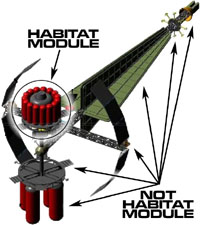
 The section of the spacecraft that the crew lives and works in is called the Habitat Module (Larry Niven calls it a "Lifesystem"). It is pressurized with a breathable atmosphere, and protects the crew from extremes of temperature and from radiation.