A planetary base is sort of like a space station on the surface of a planet or moon. The base has a focus on supporting some particular endeavour, such as a Mars Exploration mission, a military base, a planetary defense fortress, a military observation post, a military picket along the neutral zone, a trading post or "factory", a mining operation, the interstellar equivalent of a lighthouse hazard beacon, or something along those lines.
For whatever reason it makes more sense to locate the facillity on the surface of a planet instead of a space station.
The presence of a base may encourage other bases to be established in the same location (see Boomtown). This can grow to the point where the establishment becomes a full fledged colony. This can occur with both a military outpost and with a civilian commercial trading post.
The main difference between a base and a colony is that the members of a colony do not expect to ever leave.
A new base is established with rugged cargo spacecraft that can handle landing in a wilderness or otherwise undeveloped area. If the base is planned to be expanded, adding a spaceport will be a big help (even if it is just an area that has been bulldozed flat). Trading posts will put up warehouses, even if it is just a shack to hold the local product responsible for the the existence of a post on such a forlorn planet. Warehouses are also useful to store the glass beads, iron kettles, or whatever cheap junk that the ignorant natives think is valuable enough to trade for in exchange for the beforementioned valuable local product.
Like any other living system, the internal operations of a planetary base can be analyzed with Living Systems Theory, to discover sources of interesting plot complications.
A base to support the exploration of the planet. Commonly encountered as a lunar exploration base or Mars exploration base.
Fuel Depot
Fuel refining and storage facility
Industrial
Factory or smelting plant. To be located near required raw materials, and far from colonies who object to air/water/land pollution.
Mining
Base supporting mining operations, perhaps with an ore refinery.
Pirate Haven
Space pirates need infrastructure (fences for pirated loot, fuel and reaction mass, ship repairs, R&R for the crew). A hidden planetary base can act as a Pirate Haven and cater to these needs.
Planetary Defense
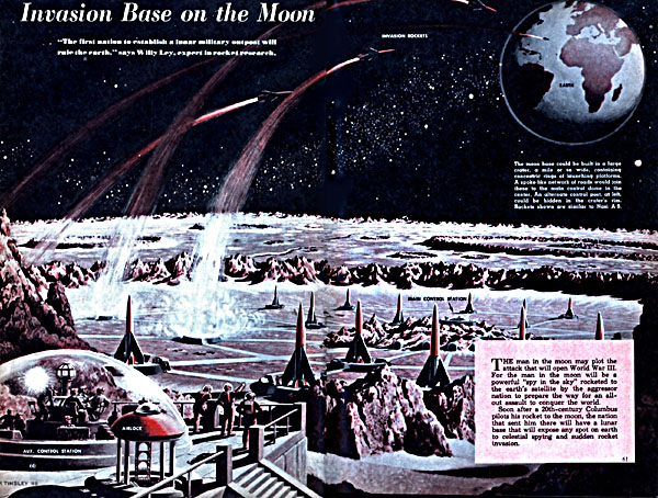
Armed military station defending its planet from outside attack, planetary fortress.
Repair Depot
Emergency cache of critical spacecraft repair tools and replacement parts. Probably under lock and key to restrict access to authorized spacecraft.
Research
Scientific research. The base either studies the planet in general or some interesting local phenomenon. Alternatively it can be for researching dangerous technologies, where the planet can be considered expendable. Though in that case it would make more sense to put the base on a space station.
Staging
Forward base to support spacecraft. May be civilian or military. Generally located in a "remote" location, remote being defined as "a long distance from the home base of the supported spacecraft." (e.g., a military base can be "remote" even if it is near a huge metropolitan planet belonging to a hostile nation).
Tax Haven / Data Haven
These are tax shelters used by the wealthy and by corporations. They are located near the planet a corporation is based on, but are outside territorial limits. More details here.
A Transport Nexus is a crossroad spaceport for passengers, a port of entry, warehouses where valuable minerals from asteroid mines are stored and trade goods transshipped, or a "trade-town".
Trading Post
"Trading Post" or "Factory" set up by a merchant to trade their imported goods with the natives in exchange for the native's valuable local goods. The base is run by the merchant, or by a "factor" who is employed by the merchant (which is where the name "factory" comes from). The preferred route between trading posts is called the "trade route", though that does not translate well into orbital trajectories. Trade routes might make sense with certain types of faster-than-light starships.
How do we begin to expand our civilization to the Moon? What are the technical issues that infrastructural engineers, in
particular, must address? This paper has the goal of introducing this fascinating area of structural mechanics, design, and construction.
Published work of the past several decades about lunar bases is summarized. Additional emphasis is placed on issues related to regolith
mechanics and robotic construction. Although many hundreds of papers have been written on these subjects, and only a few tens of these
have been referred to here, it is believed that a representative view has been created. This summary includes environmental issues, a
classification of structural types being considered for the Moon, and some possible usage of in situ resources for lunar construction. An
appendix provides, in tabular form, an overview of structural types and their lunar applications and technology drivers.
Introduction
Concepts for lunar base structures have been proposed since long
before the dawn of the space age.
Unfortunately, by the mid-1990s, the political climate turned
against a return to the Moon to stay and began to look at Mars as
the ‘‘appropriate’’ destination, essentially skipping the Moon. The
debate between ‘‘Moon First’’ and ‘‘Mars Direct’’ continues, although
it is clear that the latter will do no more for the expansion
of civilization into the solar system than did the Apollo program.
It is also clear that we do not have the technology and experience
to send people to Mars for an extended stay. Physiological and
reliability issues are yet unresolved for a trip to Mars; the Moon is
our best first goal.
The emphasis below is on structures for human habitation, a
technically challenging fraction of the total number of structures
likely to comprise the lunar facility. The test for any proposed
lunar base structure is how it meets certain basic as well as special
requirements. On the lunar surface, numerous constraints,
different from those for terrestrial structures, must be satisfied by
all designs. A number of structural types have been proposed for
lunar base structures. These include concrete structures, metal
frame structures, pneumatic construction, and hybrid structures.
In addition, options exist for subsurface architectures and the use
of natural features such as lava tubes. Each of these approaches
can in principle satisfy the various and numerous constraints, but
differently.
A post-Apollo evaluation of the need for a lunar base has been
made with the following reasons given for such a
base:
Advancing lunar science and astronomy;
Stimulus to space technology and test bed for technologies required to place humans on Mars and beyond;
Utilization of lunar resources;
Establishment of U.S. presence;
Stimulation of interest of young Americans in science and engineering; and
Beginning of long-range program to ensure survival of species.
The potential for an astronomical observatory on the Moon is
very great, and it could be serviced periodically in a reasonable
fashion from a lunar base. Several bold proposals for astronomy
from the Moon have been made. Nearly all of
these proposals involve use of advanced materials and structural
concepts to erect large long-life astronomy facilities on the Moon.
These facilities will challenge structural designers, constructors,
and logistics planners in the 21st century. One example is a 16 m diameter reflector with its
supporting structure and foundation currently being investigated
by NASA and several consortia.
Selection of the proper site for a lunar astronomical facility,
for example, involves many difficult decisions. Scientific advantages
of a polar location for a lunar base are that
half the sky is continuously visible for astronomy from each pole
and that cryogenic instruments can readily be operated there due
to the fact that there are shaded regions in perpetual darkness.
Disadvantages arise from the fact that the sun will essentially
trace the horizon, leaving the outside workspace in extreme contrast,
and will pose practical problems regarding solar power and
communications with Earth; relays will be required.
Environment
The problem of designing a structure to build on the lunar surface
is a difficult one, discussed here in a necessarily cursory way.
Many issues are not discussed, but will need to be tackled eventually.
Some important topics not discussed here, but necessary in
a detailed study, include the following:
Relationships between severe lunar temperature cycles and structural and material fatigue, a problem for exposed structures;
Structural sensitivity to temperature differentials between different sections of the same component;
Very-low-temperature effects and the possibility of brittle fractures;
Outgassing for exposed steels and other effects of high vacuum on steel, alloys, and advanced materials;
Factors of safety, originally developed to account for uncertainties in the Earth design and construction process, undoubtedly need adjustment for the lunar environment, either up or down, depending on one’s perspective and tolerance for risk;
Reliability (and risk) must be major components of lunar structures, just as they are of significant Earth structures;
Dead/live loads under lunar gravity;
Buckling, stiffening, and bracing requirements for lunar structures, which will be internally pressurized; and
Consideration of new failure modes such as those due to highvelocity micrometeorite impacts.
In a light, flexible structural system in low gravity, light structural
members (for example, composite cylinders that have a wall
thickness of only a few 1/1,000th of an inch) are sometimes designed
to limit their load-carrying capacity by buckling when that
limit is met. In turn, the load would have to be redistributed to
other, less-loaded structural members. Such an approach offers
possibilities for inflatable and other lunar surface structures where
it would be simpler and less costly to include limit-state and
sacrificial structural elements. Some of these discussions are
under way, in particular regarding
the design process for an extraterrestrial structure.
Our purpose in this paper is to discuss the technical issues and
provide some historical context. Important issues such as financing
the return to the Moon, enhancing human physiological understanding,
and many others are beyond the scope here. The
focus for us, again, is to provide the reader with a brief glimpse of
the structural and structural-related engineering issues for human
habitation on the Moon.
Important components in a design process are the creation of a
detailed design and prototyping. For a structure in the lunar environment,
such building and realistic testing cannot be performed
on the Earth or even in orbit. It is not currently possible, for
example, to experimentally assess the effect of suspended due to
1/6 g) lunar regolith lunar soil fines on lunar machinery. Apollo
experience may be extrapolated, but only to a boundary beyond
which new information is necessary.
Another crucial aspect of a lunar structural design involves an
evaluation of the total life cycle that is, taking a system from
conception through retirement and disposition, or the recycling of
the system and its components. Many factors affecting system life
cannot be predicted due to the nature of the lunar environment
and the inability to realistically assess the system before it is built
and utilized.
Finally, it appears that concurrent engineering will be a byword
for lunar structural analysis, design, and erection. Concurrent
engineering simultaneously considers system design, manufacturing,
and construction, moving major items in the cycle to as
early a stage as possible in order to anticipate potential problems.
Here, another dimension is added to this definition. Given the
extreme nature of the environment contemplated for the structure,
concurrency must imply flexibility of design and construction.
Parallelism in the design space must be maintained so that at each
juncture alternate solutions exist that will permit continuation of
construction, even in the face of completely unanticipated difficulties.
This factor needs to be further addressed and its implications
clearly explored. A discussion of lunar design codes has
already started.
Loading, Environment, and Regolith Mechanics
Any lunar structure will be designed for and built with the following
prime considerations:
Safety and reliability: Human safety and the minimization of
risk to ‘‘acceptable’’ levels are always at the top of the list of
considerations for any engineering project. The Moon offers
new challenges to the engineering designer. Minimization of
risk implies in particular structural redundancy and, when all
else fails, easy escape for the inhabitants. The key word is
‘‘acceptable,’’ a subjective consideration deeply rooted in economic
considerations. What is an acceptable level of safety
and reliability for a lunar site, one that must be considered
highly hazardous? Such questions go beyond engineering considerations
and must include policy considerations: Can we
afford to fail?
1/6 g gravity: A structure will have, in gross terms, six times
the weight-bearing capacity on the Moon as on the Earth; or,
to support a certain loading condition, one-sixth the loadbearing
strength is required on the Moon as on the Earth. In
order to maximize the utility of concepts developed for lunar
structural design, mass rather than weight-based criteria
should be the approach of lunar structural engineers. All of
NASA’s calculations have been done in kgforce rather than newtons.
Calculations are always without the gravity component;
use kilogram feet per square centimeter as pressure, for example.
In the area of foundation design, most classical analytical approaches
are based on the limit-state condition, in which the design
is based on the limit of loading on a wall or footing at the
point when a total collapse occurs—that is, the plastic limit. Since
many of the structures on the Moon require accurate pointing
capabilities for astronomy, communication, and so on, a
settlement-based design method would be more useful. Chua
propose a nonlinear hyperbolic stress-strain model
that can be used for the lunar regolith in a finite-element analysis.
The paper also shows how the finite-element method can be used
to predict settlement of the railway under a support point of a
large telescope. Chua show how a large deformation-capable
finite-element program can be used to predict the load-displacement
characteristics of a circular spud-can footing, which
was designed to support a large lunar optical telescope.
A note against assuming that less gravity means a footing can
support more load: if soil can be assumed to be linearly elastic,
then the elastic modulus is not affected by gravity. However, the
load-bearing capacity of a real soil depends on the confining
stress around it. If the soil surrounding the point of interest were
heavier because of larger gravity, the confining stress would be
higher and the soil at the point of interest could support a higher
load without collapsing.
The area of lunar soil (regolith) mechanics was exhaustively
explored in the 1970s. Much of the work was approached from
interpretation based on classical soil mechanics. Newer work and
development of nonlinear stress-strain models to describe the mechanics
of the lunar regolith can be found in Johnson. Chua show
how structure-regolith simulations can be done using the finite-element
approach.
Internal air pressurization: The lunar structure is in fact a
life-supporting closed environment. It will be a pressurized
enclosed volume with an internal pressure of nearly 15 psi.
The enclosure structure must contain this pressure and must be
designed to be ‘‘fail-safe’’ against catastrophic and other decompression
caused by accidental and natural impacts.
Shielding: A prime consideration in the design is that the structure
be able to shield against the types of hazards found on the
lunar surface: continuous solar/cosmic radiation, meteorite impacts,
and extreme variations in temperature and radiation. In
the likely situation that a layer of regolith ~lunar soil! is placed
atop the structure for shielding, the added weight would partially
(in the range of 10–20%) balance the forces on the structure
caused by internal pressurization mentioned above.
Shielding against micrometeorite impacts is done by providing
dense and heavy materials, in this case compacted regolith, to
absorb the kinetic energy. Lunar rocks would be more effective
than regolith because the rocks have fracture toughness, but may
be more difficult to obtain and much more difficult to place atop
surface structures.
Much effort in this country has been devoted to determining
the damage effects on human beings and electronics resulting
from nuclear weapon detonation, and little is being done to determine
long-term, sustained low-level radiation effects such as
those that would be encountered on the Moon. According to Silberberg, during the times of low solar activity, the
annual dose-equivalent for humans on the exposed lunar surface
may be about 30 rem (radiation equivalent man), and the dose-equivalent
over an 11 year solar cycle is about 1,000 rem, with
most of the particles arriving in one or two gigantic flares lasting
1 to 2 days. It appears that at least 2.5 m of regolith cover would
be required to keep the annual dose of radiation at 5 rem, which is
the allowable level for radiation workers (0.5 rem for the general
public). A shallower cover may be inadequate to protect against
the primary radiation, and a thicker cover may cause the secondary
radiation (which consists of electrons and other radiation as a
result of the primary radiation hitting atoms along its path).
In recent years, there has been a move away from silicon-and
germanium-based electronic components toward the use of gallium
arsenide. Lower current and voltage demand and miniaturization
of electronic components and machines would make devices
more radiation hardened.
Radiation transport codes can be used to simulate cosmic radiation
effects, which is not possible in the laboratory. One such
code that has been found to be effective is LAHET developed at the Los Alamos National Laboratory.
Vacuum: A hard vacuum surrounds the Moon that will preclude
the use of certain materials that might not be chemically
or molecularly stable under such conditions. This is an issue
for research.
Construction in a vacuum has several problems. One would be
the possibility of outgassing of oil, vapors, and lubricants from
pneumatic systems. Hydraulic systems are not used in space for
this reason. The outgassing is detrimental to astronomical mirrors,
solar panels, and any other moving machine parts because these
structures tend to cause dust particles to form pods. For more
discussion of construction challenges in the extraterrestrial environment,
see Chua. Another problem is that
surface-to-surface contact becomes much more abrasive in the
absence of an air layer. The increase in dynamic friction would
cause fusion at the interfaces, for example, a drill bit fusing with
the lunar rock. This is of course aggravated by the fact that the
vacuum is a bad conductor of heat. The increase in abrasiveness
at interfaces also increases wear and tear on any moving parts,
such as railways and wheels.
Blasting in a vacuum is another interesting problem to consider.
When the explosive in a blast hole is fired, it is transformed
into a gas, the pressure of which may sometimes exceed 100,000
terrestrial atmospheres. How this would affect the area around the
blast on the Moon and the impact of ejecta resulting from the
blast is difficult to predict. Keeping in mind that a particle set in
motion by the firing of a rocket from a lander could theoretically
travel halfway around the Moon, the effects of surface blasting on
the Moon would be something to be concerned about. Discussion
of the tests involving explosives that were performed on the
Moon can be found in Watson. Joachim discussed
different candidate explosives for extraterrestrial use, and the Air
Force Institute of Technology studied cratering
at various gravities and/or in vacuum. Bernold presented
experimental evidence from a study of blasting to loosen
regolith for excavation.
Dust: The lunar surface has a layer of fine particles that are
easily disturbed and placed into suspension. These particles
cling to all surfaces and pose serious challenges for the utility
of construction equipment, air locks, and all exposed surfaces.
Lunar dust consists of pulverized regolith and appears to be
charged. The charge may be from the fractured crystalline structure
of the material or may be of a surficial nature, for example,
charged particles from the solar wind attaching themselves to the
dust particles. Criswell reported that the dust particles
levitated at the lunar terminator (line between lunar day and lunar
night) and that this may be due to a change in polarity of the
surficial materials. Johnson discuss the issue of
lunar dust and its effects on operations on the Moon. Haljian
studied the adhesive
characteristics of regolith dust.
Ease of construction: The remoteness of the lunar site, in conjunction
with the high costs associated with launches from
Earth, suggests that lunar structures be designed for ease of
construction so that the extravehicular activity of the astronaut
construction team is minimized. Construction components
must be practical and, in a sense, modular in order to minimize
local fabrication for initial structural outposts.
Chua discuss guidelines and the developmental
process for lunar-based structures. They present the governing
criteria and also general misconceptions in designing space structures.
For example, a device that is simple and conventional looking
and has no moving parts is preferred over one that involves
multiple degrees of freedom in an exotic configuration involving
a yet-to-develop artificial intelligence control, if the former meets
the functional requirements. Other misconceptions are that constructing
on the Moon is simply a scaling of the effects of similar
operations on Earth, and that theoretical predictive tools, especially
those performed with computers, can accurately predict
events. It is also a misconception that astronauts would have to
work around the structure, rather than that, the structure would be
designed as to make construction easy for the astronauts.
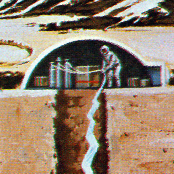
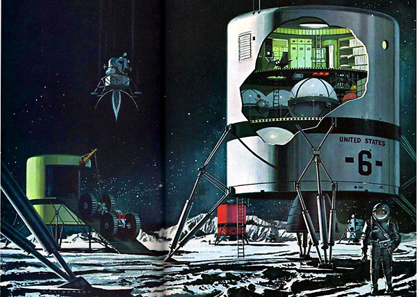
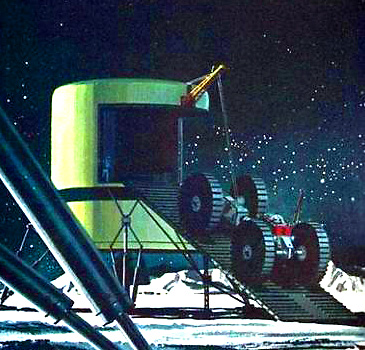
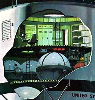
Fig. 1. Two versions of LESA modules emplaced on Moon by Boeing
in 1963
Use of local materials: This is to be viewed as extremely
important in the long-term view of extraterrestrial habitation,
but feasibility will have to wait until a minimal presence has
been established on the Moon. Initial lunar structures will be
transported for the most part in components from the Earth
(Fig. 1).
The use of local resources, normally referred to as ISRU (in
situ resource utilization), is a topic that has been studied, more
intensely now than ever, because of the possibility of actually
establishing a human presence on the Moon, near-earth orbit, and
Mars.
Possible Structural Concepts
Various concepts have been proposed for lunar structures. In
order to assess the overall efficiency of individual concepts, decision
science and operations research tools have been proposed,
used, and demonstrated. Along these lines, various concepts are compared
using a points system for an
extraterrestrial building system, including pneumatic, framed/
rigid foam, prefabricated, and hybrid (inflatable/rigid) concepts.
In a very early lunar structural design study, Johnson
presented the then-available information with the goal of furthering
the development of criteria for the design of permanent lunar
structures. In this work, the lunar environment is detailed, lunar
soil from the perspective of foundation design is discussed, and
excavation concepts are reviewed. An excellent review of the
evolution of concepts for lunar bases up through the mid-1980s is
available, as is a review of more
recent work on lunar bases. Surface
and subsurface concepts for lunar bases are surveyed with a recommendation that preliminary designs be
considered that focus on specific applications. America’s future
on the Moon is outlined as supporting scientific research, exploiting
lunar resources for use in building a space infrastructure, and
attaining self-sufficiency in the lunar environment as a first step in
planetary settlement. The complexities and costs of building such
a base will depend on the mission or missions for which such a
base is to be built.
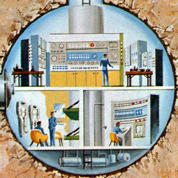
Fig. 2. Modules for lunar base
A complete Earth-Moon infrastructure uses
proven technologies and the National Space Transportation System
for early development of a lunar outpost (Fig. 2). Transfer
vehicles and surface systems are developed so that the payload
bay of the Space Shuttle can be utilized in transport. The lunar
outpost structural scheme separates radiation protection from
module support, allowing easy access, installation, and removal
of elements attached to the shuttle trusses.
Several types of structures have been proposed for lunar outposts.
A preliminary design of a permanently manned lunar surface
research base has been briefly studied by Hoffman, with criteria for the base design to include scientific
objectives as well as the transportation requirements to establish
and support its continued operations.
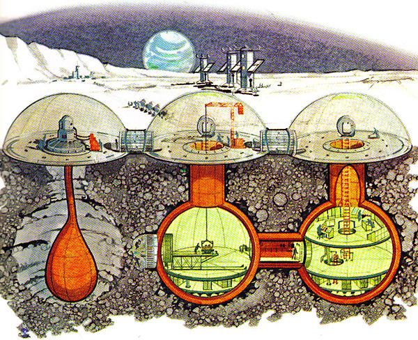
Fig. 3. Inflatable structure
Inflatables
A pillow-shaped structure proposed by Vanderbilt as
a possible concept for a permanent lunar base (Fig. 3) consists of
quilted inflatable pressurized tensile structures using fiber composites.
Shielding is provided by an overburden of regolith, with
accommodation for sunlight ingress. These studies of the inflatable
concept are continued by Nowak with consideration
of the foundation problem and additional reliability concerns
and analysis. This concept is a
significant departure from numerous other inflatable concepts in
that it shows an alternative to spheroidal inflatables and optimizes
volume for habitation. Inflatable structural concepts for a lunar
base are proposed as a means to simplify and speed
up the process while lessening the costs. The inflatable structure
is suggested as a generic test-bed structure for a variety of application
needs for the Moon.
Another pressurized membrane structure, proposed by Chow for a permanent lunar base, is constructed of
a double-skin membrane filled with structural foam. A pressurized
torus-shaped substructure provides edge support, and shielding is
provided by an overburden of regolith. Briefly, the construction
procedure requires shaping the ground and spreading the uninflated
structure upon it, after which the torus-shaped substructure
is pressurized. Structural foam is then injected into the inflatable
component, and the internal compartment is pressurized. The bottoms
of both inflated structures are filled with compacted soil to
provide stability and a flat interior floor surface. Backfilling is a
difficult operation to carry out through an airlock. It will, of
course, be crucial to ensure that the interior is dust-free (Fig. 4).
A detailed architectural master plan is also proposed for a horizontal
inflatable habitat. Finite-element simulations
of inflatable structures are needed because it is very difficult
to reproduce a hard vacuum and low-gravity condition on Earth.
The finite-element modeling would have to be large-deformation
capable and have membrane elements (which are essentially
beam elements that are without bending stiffness) and axial tensile
stiffness, but not axial compression stiffness. The program
should also ideally be able to model regolith-structure interaction.
GEOT2D is a program that has the capabilities
needed to simulate inflatable structure-regolith interaction.
Erectables
An expandable platform suggested by Mangan as a structure
on the Moon consists of various geometrically configured 3D
trussed octet or space frame elements used both as building
blocks and as a platform for expansion of the structure. Examples
of the shapes to be used include tetrahedral, hexahedral, octahedral,
and so on. This effort is primarily qualitative.
A concept proposed by King would use the liquid
oxygen tank portions of the Space Shuttle external tank assembly
for a basic lunar habitat. The modifications of the tank, to take
place in low Earth orbit, will include the installation of living
quarters, instrumentation, air locks, life-support systems, and environmental
control systems. The habitat is then transported to the
Moon for a soft landing. This idea, if proven economically feasible,
may provide the most politically palatable path to the lunar
surface, with the added advantage that many of the necessary
technologies already exist and only need resurrection (similar to
Fig. 2).
A semiquantitative approach to lunar base structures provided
by Kelso gives some attention to economic considerations,
and the structural concepts included could be developed
in the future. A modular approach to lunar base design and construction
is suggested by Schroeder as a flexible
approach to developing a variety of structures for the lunar surface.
In a related vein, a membrane structure is suggested for an
open structure that may be used for assembly on the lunar surface
by Schroeder. A tensile-integrity structure has been
suggested as a possible concept for larger surface structures by
Benaroya (Fig. 4).
Concrete and Lunar Materials
A structural analysis and preliminary design of a precast, prestressed
concrete lunar base is reported by Lin. In
order to maintain structural integrity, and thus air tightness, when
differential settlement is possible, a floating foundation is proposed.
All materials for such a lunar concrete structure, except
possibly hydrogen for the making of water, may be derivable
from lunar resources. Horiguchi study simulated
lunar cement.
The use of unprocessed or minimally processed lunar materials
for base structures, as well as for shielding, may be made
possible by adopting and extending terrestrial techniques
developed in antiquity for harsh environments. A variety
of materials and techniques discussed are candidates for unpressurized
applications.
The use of indigenous materials is considered by Happel for the design of a tied-arch structure. The study is
extensive and detailed and also includes an exposition on lunar
materials.
Construction of layered embankments using regolith and filmy
materials (geotextiles) is viewed as an option using robotic construction, as are fabric-confined soil structures.
In order to avoid the difficulties of mixing concrete on the
lunar surface due to lack of water, Gracia
have suggested examining use of sulfur concrete because sulfur is
readily available on the Moon.
Lava Tubes
Ideas regarding the utility of constructing the first outposts under
the lunar surface have been proposed. A preliminary assessment is
provided by Daga of a lunar outpost situated in a
lava tube. They conclude that an architectural solution is needed
to the problems surrounding the development of a lunar outpost,
but that lunar surface structures are not the best approach. Rather
subselene development offers real evolutionary potential for
settlement.
In another structural approach, fused regolith structures are
suggested by Cliffton. In this
case, the structures are small and many and reside on the surface.
A prime advantage offered for planning numerous smaller structures
is safety and reliability. The premise of this work is to use
the sun’s energy to fuse regolith into components.
Construction in New Environment
Site plans and surface system architectures are forcefully presented as being fundamental
to any development of structural concepts. One of the
challenges to the extraterrestrial structures community is that of
construction. Lunar construction techniques have differences
from those on Earth; for example, the construction team will
likely operate in pressure suits, motion is dominated by 1/6 g,
solar and cosmic radiation are not shielded by an Earth-type atmosphere,
and suspended dust exists in the construction site.
Toups assesses various construction techniques for the
classes of structures and their respective materials.
Structural and architectural designs along with manufacturing
plants and construction methods are discussed by Namba for a habitable structure on the Moon using concrete
modules. The module can be disassembled into frame and panels.
A qualitative study by Drake is made of the
design and construction of a lunar outpost assembly facility. Such
a facility would be used to construct structures too large for transport
to the Moon in one piece. The assembly facility would also
be used to support operation and maintenance operations during
the functional life of the lunar outpost. A series of trade studies is
suggested on the construction of such an assembly facility.
Construction of a lunar base will at least partially rest on the
capabilities of the Army Corps of Engineers. Preparations that are
now under way are outlined by Simmerer and challenges
discussed by Sargent.
All the above are contingent on the ‘‘practical’’ aspects of
building structures on the Moon. These aspects include the sort of
machinery needed to move equipment and astronauts about the
surface; the methods needed to construct in 1/6 g with an extremely
fine regolith dust working its way into every interface and
opening; and the determination of the appropriate layout of structures
considering human safety and operations needs. Using harsh
Earth environments such as the Antarctic as test beds for extraterrestrial
operations is advocated by Bell.
The performance of materials and equipment used for lunar
construction needs to be examined in terms of the many constraints
discussed so far. Structures that are unsuitable for Earth
construction may be adequate for the reduced-gravity lunar environment. Several research efforts have been
directed to producing construction materials, such as cement, concrete,
and sulfur-based materials, from the elements available on
the Moon.
The appendix to this paper provides a long list of structures
that require a study not only of the materials that could be used
for construction, but also of the necessary tools/equipment, methods
of operation/control, and most importantly, how to construct
structures with and within the lunar environment (that is regolith,
vacuum, 1/6 g). Because most of the construction methods developed
since the beginning of mankind are adapted to fit and take
advantage of terrestrial environments (that is, soil characteristics,
atmosphere with oxygen, and 1 g gravity), technologies that are
common on Earth either will not work on the Moon or are too
costly or inefficient. The following sections will address some of
the unique problems and circumstances that we face.
Creating Base Infrastructure
The availability of an adequate infrastructure is key to the survival
and growth of any society. ‘‘In all human societies, the
quality of life depends first on the physical infrastructure that
provides the basic necessities such as shelter, water, waste disposal,
and transportation,’’ wrote Grigg. Today, and especially
for the lunar base, we have to add communication and
power as part of the physical infrastructure. All of these constructed
facilities have one issue in common, namely the interaction
with lunar surface materials: (1) rocks; (2) regolith; and (3)
breccias. Lunar soil, referred to as regolith, differs from soil on
Earth in several respects that are significant for construction.
While the soil that establishes the top layers (10–20 cm) is loose
and ‘‘powdery,’’ easily observable in Apollo movies, the regolith
reaches the relative density of 90–100% below 30 cm. The grain
size distribution of a common regolith, as well as its high density
below the top layers, is hardly found in the terrestrial environment.
This creates unique problems for excavating, trenching,
backfilling, and compacting the soil. These
operations, however, are needed to create (1) building foundations;
(2) roadbeds; (3) launch pads; (4) buried utilities (power,
communication); (5) shelters and covers; (6) open-pit mining; and
(7) underground storage facilities.
Excavating ‘‘Hard’’ Lunar Soil
Fig. 5. Common ‘‘Earth’’ excavators that depend on gravity
Fig. 6. Effect of buried explosive charges on lunar soil simulants: (a) ejecta milliseconds after detonation; (b) effect of 1/8 g PETN buried at 7.1
cm; and (c) detonation chamber, chimney, and crater after removal of loose soil
Bernold reported about efforts to study the unique problems
related to digging and trenching on the Moon. All the common
excavation technologies used on Earth depend on the effect
of gravitational acceleration that turns mass into forces that are
needed to cut, scoop, and move soil (Fig. 5).
Because of the drastically reduced gravity, transporting the
masses and material to the lunar surface would be prohibitively
expensive. Dick presented the result of experimental
work to study an alternative to traditional excavation of soil,
namely the use of explosives to loosen the dense soil so it can be
excavated with a limited amount of force. Fig. 6 presents images
of the effect of a small amount of explosives on lunar simulants.
Fig. 6(a) shows the direction and position of ejecta clumps
43.16 and 52.24 ms after detonation, while Fig. 6(b) presents an
overview and 6(c) a cross section of the crater created by a small
amount of explosives. Although the ejection of regolith would not
be acceptable on the lunar surface, since the resulting dust would
travel far, research showed that explosives buried deep enough
would not create craters but loosen the soil very effectively. In
fact, Fig. 5(b) demonstrates how a lightweight bucket pulled by a
cable was slicing into the lunar soil simulant that had been loosened
in this manner. Furthermore, the sensor-equipped lightweight
backhoe excavator required a drastic reduction of energy
to dig the loosened soil.
Building Transportation Infrastructure
The creation of durable roads without using asphalt or concrete as
a top requires the planning/cutting of the existing surface and the
compaction of fill material. The main objectives of the road base
and road surface are to distribute the point loads under the
wheels/tracks to the maximum allowable bearing capacity, to provide
stable traction resistance for the needed rim pulls (force at
the rim of the wheel to allow motion) and breaking forces, and for
abrasion resistance. Earthbound equipment that achieves these
objectives depends on a large mass, gravitational force, and a
sufficient power source. It is obvious that the size of each would
make it cost-prohibitive to deploy on the Moon, even if the power
source were switched from diesel engines to electric. In addition,
Bernold showed that the compaction of lunar soil necessary
for creating a stable roadbase would create unique problems.
Preliminary research data indicated that the normal size distribution
of soil particles would make it impossible to achieve needed
density and strength using common methods of static or vibratory
compaction.
However, reducing the percentage of fines present in the regolith
can increase the compacted strength of the dry and mainly
cohesionless lunar soil. In addition, the surface has to be covered
with larger-size stones that have to be crushed from rock, requiring
additional equipment such as rock-drill and pyrotechnic
equipment, loaders, rock crushers, vibrating screens, and conveyor
feeders. It is apparent that the construction of trafficable
and stable roads and/or pads on the Moon will require many
different machines capable of pushing, loading, cutting, sizing,
and compacting regolith as well as the crushing, transportation,
spreading, and compaction of rock. The use of multipurpose
equipment will certainly be desirable but, on the other hand, slow
the operation. If one wants to rely on ‘‘Earth-proven’’ technologies,
significant disadvantages will have to be overcome. The
most significant handicap is the large reduction of gravitational
acceleration that is the basis for the efficient operation of terrestrial
roadbuilding equipment.
Fig. 7. Robotic transportation system for lunar base
As an alternative to wheel-or water-based transportation, Bernold proposed a cable-based transportation system:
‘‘Lunar tramway systems can take advantage of the reduced gravity,
which permits building wider spans and/or using smaller
cable diameter for lifting and transporting heavy loads. The use of
luffing masts and a unique semistable rigging platform provide
many opportunities for reaching wide areas on the lunar surface
and performing various tasks needed for handling material, construction,
servicing and maintaining facilities needed on a lunar
base.’’ Fig. 7 presents the basic elements of a cable-based transportation
system that could cover large areas.
As depicted in Fig. 7, the track cables are attached to two (or
more) masts, thus being able to span long distances (for example,
3,000 m) because the lower gravity reduces not only the weight of
the load to 1/6, but also the weight of the cable itself, leading to
much smaller cable deflections than on Earth. Two electrowinches
and cables at each mast provide the mechanism for luffing (sideways
rotation around its base socket) the track cables. As indicated
in Fig. 7(a), the luffing mechanism adds a significant capability
in that it allows the transportation system to cover a
rectangular area. In addition, the mast and cables can be lowered
all the way to the ground during the final landing approach of a
cargo ship. Fig. 7(b) presents the concept of a trolley-carriage that
is being moved along the track by a haul cable. Attached to the
carriage are either three or six lift cables that can be individually
operated with winches. By combining these cable-based mechanisms,
a spatially controlled platform can be established. While the system can be used to unload a lunar
lander, it can also support construction and mining operations.
Fig. 8 portrays a platform attachment capable of (1) excavating
trenches to bury cables and pipes; (2) removing rock boulders; (3)
collecting rocks for the crusher; (4) deploying soil or rock drills;
and (5) mining open pits for processing.
Fig. 8. Cable-based robot shovel excavator at work
As shown in Fig. 8, the same spatially constrained platform
supporting a cargo-handling robot can be reconfigured to carry a
shovel excavator capable of loading regolith and rock boulders
into a pan mounted on top of the platform. For other operations,
such as trenching, the same robot arm could reconfigure itself to
work as a backhoe, drill boom, or other desirable end-effectors.
A major problem that needs to be considered in the design of
robotic systems for construction is the question of control. The
complexities of working in a totally new environment will make
it impossible to have the lunar construction equipment operate
autonomously. Kemurdjian discuss several
specific aspects of the problem. These include the effects of
low gravity on traction, the amount of power to be consumed, and
most importantly, the dynamics of such vehicles. At the same
time, the problems associated with exposing astronauts to long
prolonged extravehicular activities (EVA) and the cost of deploying
human operators on the lunar surface make it unlikely that
each piece of equipment will be steered by an operator who rides
on it.
Robotic Control of Construction Equipment
One of the main problems in robotic control of equipment is the
time that signals need to travel through vacuum, atmosphere, or
fiber-optic or other communication lines. The time it takes a signal
to travel through a network is commonly referred to as latency.
Nelson report about their work on the issue of
latency: ‘‘Teleoperation is commonly used in the remote control
of terrestrial mining equipment. Teleoperating mining equipment
on the Moon from the Earth is attractive but involves a transmission
loop time delay of 4 to 10 s. A human operator can handle
time delays of about 1 second in simple teleoperation applications.’’
A variety of control schemes that help alleviate the problems
caused by excessive signal delays have been developed.
They range from teleautonomous, to predictive teleoperation, to
semiautonomous operation. In this context,
one effort by researchers is to equip mobile computerized equipment
with the robustness and intelligence to react to the dynamics
of the environment. To do this, it is critical ‘‘to build complete
agents which operate in dynamic environments using real-time
sensors. Internal world models which are complete representations
of the external environment, besides being impossible to
obtain, are not at all necessary for agents to act in a competent
manner’’. Since work in construction always
requires moving within, and interacting with, a complex environment
while handling messy materials that have to be joined, layered
on top, inserted, and so on, a distributed intelligence embodied
in the site equipment and sensors and communicating via
networks may serve as a uniquely qualified approach to creating a
semiautonomous fleet of equipment.
Fig. 9. Layered control architecture for Earth-based teleoperation of
lunar equipment
Fig. 9 presents a partial model of layered control architecture
for a teleoperated backhoe operation that integrates human control
with intelligent control modules that work in parallel rather
than in sequence. The layered control architecture for robotic excavation
was first proposed by Huang.
The key feature of this approach is the distribution of the control
task to the most efficient module.
Issue of Water on Moon
In a recent development, it appears that there may be water-ice in
some craters near the poles of the Moon. It was suggested that
water-laden comets and asteroids may have deposited the water. If
water does exist in those craters, it was conjectured by Chua and
Johnson ~1998) that the moisture distribution may consist of
water-ice mixing with the regolith to saturation or near saturation,
and reducing outward according to the matric suction pressure
~which is influenced by the particle size distribution). Since the
gravitation potential is relatively small compared to the matric
suction potential, the water would have been drawn laterally or
even upwards over some distance. ~Note: Since the regolith has
no clays, unlike Earth, there would not be an osmotic suction
component to influence moisture migration.) The extent of this
unsaturated zone is primarily influenced by how fast the water
vapor condensed at the bottom of the crater, which have temperatures
as low as 2230°C. The Lunar Prospector Mission team
indicated that the moisture content in the regolith at the bottom of
the crater might be between 0.3 and 1%.
Issue of using Geosynthetics in Extraterrestrial
Environment
Some recent papers suggested using geosynthetics as soil reinforcement
to construct earth structures such as berms, walls, and
slopes. Several problems have to be considered in order for this to
be a reality.
Plastic materials are susceptible to degradation when subjected to radiation;
The glass transition temperature of many if not all of the geosynthetics used on Earth is well above the cold temperatures encountered on candidate sites, including that on the Moon, which would make the plastics brittle, thus rendering them useless as reinforcing elements; and
There is little experience on how geosynthetics fare in a hard vacuum and respond to the relatively more abrasive regolith.
Conclusion
We have presented a summary of current thinking regarding some
of the issues surrounding the engineering and construction of
structures for long-term lunar human habitation. We close here
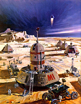
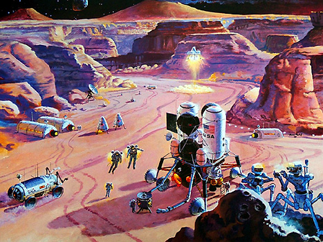
with a NASA vision of how a lunar base may look (Fig. 10).
Fig. 10. Lunar habitat assembled out of components delivered by
automated cargo flights. Pressurized rovers, logistics modules, and
spacesuit maintenance and storage module combine to provide living
and working quarters for crew ~NASA/JSC image #S93-45585!.
What’s the most practical way to sustain a permanent Moon base through the two-week lunar night? In March of 2014, the Sacramento L5 Society (SL5S), a California chapter of the National Space Society, undertook the task of answering that question, eventually resulting in a detailed analysis of 20 different potential energy delivery systems. This article is a summary of the findings of the SL5S analysis to date. The detailed analysis itself and its accompanying spreadsheet, including a full description of the 20 systems the SL5S has studied to date, can be found on the SL5S website.
History of this analysis
In early 2014, two college students, Akhil Raj Kumar Kalapala and Krishna Bhavana Sivaraju of Rajiv Gandhi University in India, proposed beaming space-based solar energy to the Earth by way of a laser beam located in geosynchronous orbit. On March 14, 2014, an informal “brown bag” Moon Base Working Group (MBWG) started at NASA Ames Research Center in California “to develop a cost-effective plan for establishing and operating the NASA Moon Base that would be within 10% of the total NASA budget.” In March of 2014, Joseph Bland of the SL5S, one of the mentors for Akhil and Krishna, suggested to Michael Abramson, a member of both the SL5S and of the NASA Ames MBWG, that the group examine the possibility of powering a Moon base through the lunar night with a laser either at L1 or in lunar orbit.
Assumptions
Because it takes less energy to put a given mass into low Earth orbit (LEO) than into lunar orbit, and less energy to put a mass into lunar orbit than onto the lunar surface, it is useful to use a given lift capacity to determine relative masses of different systems in different locations. In the SL5S analysis, the lift capacity is defined in SpaceX Falcon Heavy (FH) units. One FH has a liftoff mass of 1,462,836 kilograms. It is assumed that one FH can put 53,000 kilograms into LEO, 17,216 kilograms into either a lunar or Earth-Moon L1 (EML1) orbit, and 5,739 kilograms onto the lunar surface.
Mass doesn’t necessarily have to be lifted directly from Earth to its final destination. For some SL5S calculations, it is assumed that the propellant and electric propulsion (EP) drive used to move a mass from LEO to either lunar orbit or EML1 will equal 30 percent of the transported mass. An EP system can also be used for orbital station keeping, which can be broadly defined as maintaining an object in space in a preferred position or orbit
The SL5S analysis examined energy storage by flywheel, electric battery, chemical, and thermal battery systems. It was concluded that lithium-sulfur (Li-S) batteries presently appeared to have the best specific energy (measured in kilowatt-hours per kilogram), but that other systems would benefit greatly from in situ resource utilization (ISRU) and would become competitive fairly rapidly once manufacturing on the lunar surface began. A specific energy of 0.5 kilowatt-hours per kilogram for Li-S has been used in the SL5S analysis as the basis for energy storage mass calculations for all systems.
As originally suggested by SL5S member Roger Arnold, aggressive collimation of a laser beam with a Fresnel optical lens could be used to dramatically reduce the diameter of a laser beam over a long distance since, for a given light wavelength and distance to target, spot diameter is inversely proportional to aperture diameter. Aggressive laser collimating may be especially practical in a weightless, weather-less environment. Because objects in space are weightlessness, and because space has no atmosphere, a space-based Fresnel laser collimating lens might only be a few mils thick. In this analysis, the mass of a Fresnel lens, including the mounting framework, is assumed to be 0.25 kilograms per square meter, with most of that mass assumed to be in the mounting framework.
Two different different approaches to powering a laser were examined. One uses electricity to power the laser. The system utilizes photovoltaic cells, although the electricity can also be created by a heat engine driven by concentrated solar energy. Another type of system is possible using solar-pumped lasers. In such a system, the solar insolation is concentrated directly on the laser, bypassing the electrical conversion system. Efficiencies for the two systems are expected to eventually be about the same, but the solar-pumped one appears to have a higher specific power even at present efficiencies.
A satellite that is not in sun-synchronous lunar orbit will move regularly into the Moon’s shadow. Adding an energy storage system permits an orbiting laser system to continue beaming energy even when this occurs. This energy storage system can also be used with a sun-synchronous satellite to store energy until the laser system can regain direct contact with the lunar base. Finally, by leaving parts of the energy storage system in orbit rather than moving it to the lunar surface, the overall project mass can be reduced, since rocket motors, fuel, and so on can be scaled back.
A deflecting system, as the term implies, permits a laser beam to be deflected. In certain circumstances, such a system in lunar orbit may permit nearly uninterrupted laser beaming from an orbiting solar-powered laser system to a given location, thus obviating the need for energy storage either in orbit or on the lunar surface.
A deflecting can also find use in other ways. It is possible to envisage a series of non-orbiting deflection modules placed directly on the lunar surface to transfer beamed energy to other locations. Finally, a surface-based solar powered laser system at the lunar poles may beam solar-powered laser energy to an orbiting deflecting system, distributing lunar pole-generated laser energy to other locations on the Moon (see Lunar Polar Multi-array System below).
The 2009 NASA concept study
In January of 2015, the SL5S analysis was essentially complete when the organization discovered a presentation titled “NASA JSC Lunar Surface Concept Study.” Since January, SL5S conducted an extensive rewrite of its analysis to actively compare the earlier analysis with the 2009 NASA study.
The preferred system recommended in the 2009 NASA study was a photovolatic solar array-powered cryogenic storage regenerating fuel cell system. NASA calculated that a five-kilowatt continuous delivery system would store 2,000 kilowatt-hours with a system energy density of 1.15 kilowatt-hours per kilogram. The study’s alternate preferred system was a fixed orbit laser system, with a 16.1-hour orbit period that required a surface receiver installation with 525 kilowatt-hours of energy storage. The laser was powered and fired when it was both in direct sunlight and in direct line-of-sight with the Moon base.
Other approaches
One concept that was not explored in the 2009 NASA study is the use of several separate solar collectors situated on high lunar mountain peaks, or so-called “peaks of eternal light,” each connected directly to the base via electric cables, lasers, or reflected solar beams. This concept was suggested by SL5S member Michael Abramson in early February of this year. Such a system would approach a continuously-powered polar Moon base. Periods of darkness as long as 36 hours may still be likely, requiring additional energy storage capacity, estimated at 540 kilowatt-hours.
Yet another approach to continuously powering a Moon base was looked at and rejected by NASA as impractical. That approach involved parking a solar-powered laser system at the Earth-Moon L1 or L2 points. However, in making its determination, NASA did not consider the possibility of using aggressive laser collimating.
For any two bodies in space rotating about a common center, there are five points of special interest called Lagrange points. For the Earth-Moon system, they’re called EML1, EML2, and so on.
In the case of EML1, this point is between the Earth and the Moon and along a line between their centers of gravity. In the case of EML2, this point is along the same line but beyond the far side of the Moon. The Lagrange points mark positions where the combined gravitational pull of the two bodies precisely matches the centripetal force required for the points to orbit with those bodies. For example, an object placed at EML1 orbits at the same rate as the Moon even though it is much closer to the Earth.
Lagrange points L1, L2 and L3 are said to be unstable. That is, it requires a force to maintain an object’s position in their vicinity. One type of orbit, called a “halo orbit,” while also unstable, is much more stable than an object placed exactly at one of these Lagrange points. A halo orbit is a three-dimensional somewhat circular orbit approximately perpendicular to the center line connecting the Earth and the Moon at the approximate location of the Lagrange point along that line.
The oscillating Lagrange point orbit
Presently, station keeping in the vicinity of EML1 or EML2 is usually accomplished by a three-dimensional halo orbit. An alternative approach known as the oscillating Lagrange point orbit (OLO), is largely a two-dimensional orbit in the two-body orbital plane. The figure below generally illustrates the theorized course of an OLO over the roughly four weeks of a lunar rotation, as mapped along the approximately 6,400-kilometer line of travel of L1 relative to the Moon between perigee and apogee.
Looked at from above or below the Earth-Moon plane, the OLO approximates a figure eight, orbiting alternatively along the lobe on one side of the line connecting the center of the Earth and the center of the Moon and then along the lobe on the other side of that line. Note that the center line is relative to Earth and Moon and is described by the elliptical movement of the Moon as it orbits around the Earth/Moon barycenter. SL5S member Roger Arnold, originator of this concept, put it this way:
“The metastable neutral point that the station should track is not the L1 point, wherever it happens to be at any given moment. Rather, it’s a point in the 6D phase space for the system (x, x-dot, y, y-dot, and z, z-dot). I.e., both position and velocity vectors must be right. When they are, the station describes an oscillating “orbit” that passes through the L1 point twice per month. Once the station achieves the neutral point, I believe the only station keeping that’s needed is to correct for drift due to measurement errors and unaccounted solar radiation pressure. The neutral point that the station follows will oscillate with the L1 point, but with lesser amplitude and lagging in phase. The proper analogy is to balancing a weight atop a pole whose base is oscillating back and forth. The weight does not precisely track the base and remain positioned exactly above it.”
The OLO appears to be able to operate in much closer proximity to the Lagrangian point with which it is associated than a halo orbit. This is important for beaming energy to the lunar surface from EML1 or EML2. Work is presently being carried out by the SL5S to roughly estimate the extents of a typical OLO at EML1.
Solar sail propulsion and the gravity winch
In certain circumstances, a solar sail arrangement can be used to enhance or even replace an electric propulsion system for OLO station keeping purposes at EML1/EML2. This system has an advantage because of its ability to modify a spacecraft’s position without using fuel. A related idea is the use of reels to pull in or let out either solar sails or “gravity anchors” relative to a space-based platform. This constitutes what might be called the concept of a “gravity winch.” A gravity winch is basically a reeled tether that’s dropped down gravity wells from a “neutral” gravity point, such as a Lagrange point. In the case of a platform at EML1, a tether can be dropped from the platform down the gravity wells of both the Moon and Earth. Shifting the gravity anchors from one side of the platform to the other allows the EML1 platform to “balance” between the two gravity wells, similar to the way a pole helps a tightrope walker balance. This technique may also be useful for putting in place a “lunar elevator” extending from EML1 to the lunar surface.
Results and conclusions
The table below collates the results of our analysis. The Cryogenic-storage Regenerating Fuel Cell (CRFC) and Fixed Orbit Laser System (FOLS) systems are included for reference purposes only. This presumes that any advances in battery technology will be applied across the board to all systems. To aid in comparisons, a CRFC-type system using Li-S energy storage is included as the Lunar Non-polar Surface Mounted System (LNSMS). Also, a FOLS-type system using Li-S energy storage and aggressive laser collimating is included as the Lunar Orbiting Photovoltaic-powered Laser System (LOPVLS).
In the table, the 15-kilowatt continuous systems are shown ranked from low cost to high cost by the column “Tot FH $ without EP” (Total Falcon Heavy cost without electric propulsion). It is assumed that, for an initial Moon base, electric propulsion will not be used to deliver the payloads to their ultimate destinations. FH dollars are calculated based on a price of $1,200 per kilogram in accordance with the statement by SpaceX CEO Elon Musk that, “Ultimately, I believe $500 per pound or less is very achievable.” It’s important to note that FH dollars do not include any costs associated with developing the various systems shown in the table.
The findings of the SL5S analysis are very much first order approximations. In addition, the analysis is still a work in progress. However, in light of the dramatic nature of those findings, it is felt that the systems in question merit a far more in-depth analysis than the S5LS is capable of delivering. It is hoped that this article will inspire the undertaking of such an in-depth analysis by NASA or some other interested party.
We propose using the temperature gradients between the Moon’s surface and the soil at a certain
depth to power an Organic Rankine Cycle that could supply a permanent installation, particularly at
night, when solar power is not available. Our theoretical and engineering considerations show that,
with existing working fluids and quite feasible technical requirements, it is possible to continuously
yield 25kW to sustain a 3 member crew.
1. Introduction
Indeed, the Moon can unravel unique opportunities
for science, engineering and resource
exploitation. As an example of scientific and
engineering goals, we could mention the advantageous
opportunities for further lunar laser
ranging, astronomy, due to the inexistence
of an atmosphere, and radio-astronomy.
It is also well know that Moon’s soil is particularly
rich in He3, the fuel of the future fusion
nuclear reactors. Furthermore, the impact
of comets and asteroids on the Moon are important
sources of metals, ice and compounds that
can supply humankind for many centuries.
In fact, the colonization of space presents a
number of technical challenges, most of which
are yet to be overcome. One of which is how
to ensure a sustained power supply given the
specific conditions of the Moon.
The power requirements of an initial lunar
base camp with 3 crew members have been estimated
at 25kW. However an advanced base
with an industrial or mining operation could
need over 1MW.
A key feature of the lunar environment when
considering long term settlement is the length
of the day-night cycles. The moon has a rotation
period of approximately 27 days, which is
tidally coupled with its orbital period around
Earth. This means each day and night on the
Moon lasts for approximately 14 Earth days.
This poses a problem regarding a continuous
power supply.
The thermal amplitudes on the Moon are
extreme, oscillating between day and night
mean temperatures of approximately 380K and
120K, respectively.
Figure 1:
Lunar regolith temperature profile from measurements conducted by Apollo astronauts.
Owing to these sharp temperature amplitudes,
the lunar soil has significant temperature
gradients with depth. Measurements conducted
during the Apollo lunar landings show
that at depths below 80 cm in the lunar regolith
the day-night temperature variations are
no longer present. Even below 50 cm the temperature
fluctuations are on the order of only
±1 K. The mean soil temperatures in the first
few meters where the measurements were taken
are on the order of 250 K and there is a temperature
gradient of the order of 1 to 3 K/m
(ct. Figure 1). The gradient arises from the
heat flow from the Moon’s crust.
The default option for supplying power to a
lunar colony has been to use photovoltaic cells
in solar panels, similarly to most power systems
in space. The use of solar panels as the exclusive
power source, requires some kind of energy
storage to cover for periods in the shadow.
However, current battery technology is far from
being able to cover for 14 days without sunlight,
unless massive battery farms were to be used.
There have been proposals to store thermal
energy in a heat mass made of processed lunar
regolith. In this concept, a solar power concentrator
heats a mass of compacted lunar regolith
to high temperatures. The stored heat is then
used during the night to power a Stirling engine
that produces electricity.
The presence of the aforementioned temperature
gradients in the Moon’s soil presents an
opportunity to build a thermodynamic power
system that can ensure the long-term continuity
of power supply on the Moon. Our proposal
is to use these temperature gradients to
power a thermal engine to supply an installation
with uninterrupted power. The main issue
when considering classic thermal power systems,
usually based on water or air as working
fluid, is that they require very high temperatures
only achievable either by burning some
kind of fuel or through concentration of solar
power.
Recently, however, there has been an increasing
number of proposals on the application
of what is usually called an Organic Rankine
Cycle (ORC), which has been proposed as
an alternative for power generation from low-temperature
heat sources such as solar heat,
waste heat or geothermal energy. This cycle
is characterized by the use of an organic
working fluid instead of water, allowing for heat
conversion in low-temperature sources.
The organic working fluids typically have much
lower melting and boiling temperatures than
water, allowing the engine to work at lower
heat source temperatures. Many of the working
fluids employed are the ones commonly used
in refrigeration cycles. Current applications of
ORC on Earth include cogeneration facilities, Ocean Thermal Energy Conversion
and low-grade geothermal heat sources.
In this paper, we propose that an ORC can
be used effectively as the basis of a thermal
power system using the temperature gradients
in the Moon’s soil, particularly, during the long
lunar night. As we explore a set of possible
working fluids, we examine the feasibility of an
ORC to power a lunar colony during its long
nights and estimate its performance.
For details about the fusion powered transport ship, go here.
4.5 Asteroid Base
The mission assumes an asteroid mining operation with a 5000 person habitat. The complex transportation scenario for this advanced mission involves four different vehicles and three separate space bases (refs. 86 and 91).
c. The GEO base serves as the final assembly area for the large fusion rocket system
used to propel payloads out to the asteroids. Cargo and propellant are unloaded
from electric-powered transfer vehicles sent up from the LEO base. The enlarged
OTV used to transfer personnel and priority cargo is designed to transport 441,000 lb
(200,000 kg) from LEO to GEO. The complex fusion propulsion system is assembled
at the base with the fusion power core, propellant tanks, large thermal radiators,
and the personnnel and priority cargo modules. The resulting vehicle, shown in
figure 4-11, can transport 1250 passengers and 150 metric tons of priority cargo to
the asteroids.
The gross start mass for the resupply mission would be 10,000 metric tons, of which power plant comprises 2000 tons; hydrogen propellant, 4000 tons; and payload, 4000 tons (1250-person habitat plus consumables and priority cargo). The power plant consists of two 6 GW fusion reactors utilizing the deuterium-deuterium fusion reaction. The total power plan provides 4.8 GW of thrust power while radiating almost 2.8 GW of waste heat and 4.4 GW of high energy neutrons.
d. There are two methods the fusion rocket will use to propel vehicles to the asteroid
base: fast transfer for personnel and priority cargo, and slow transfer for
nonpriority cargo. The manned resupply mission is a fast hyperbolic transfer orbit
consisting of an 11-day thrust period to achieve hyperbolic velocity, followed by a
226-day coasting, and a 13-day deceleration to match velocity with the asteroid
base. The return mission leaves the asteroid approximately 113 days later for a
reverse of the ascent mission.
The second method is used to accelerate unmanned cargo pods on a slow elliptical (Hohmann) transfer orbit out to the asteroid base. Figure 4-12 illustrates the different trajectories. The slower trip takes 130 days longer but costs less than half of what the fast, hyperbolic trip costs. All nonpriority cargo is brought to the asteroid facility in this manner. Empty cargo pods are not returned to Earth, they may be discarded or used in a variety of ways as storage modules or Closed Ecological Life Support System (CELSS) modules.
e.A fleet of two fusion rockets is envisioned. They each make one round trip per asteroid orbit (synodic cycle) to the asteroid mining facility and leave a few days apart. Because of the synodic cycle, the fusion rocket vehicles are delayed at the asteroid base for approximately 113 days, at the GEO location they are delayed approximately 288 days. During these delays the fusion rockets are used to decelerate unmanned cargo pods at the asteroid base and to accelerate the pods at GEO. Cargo pod launches are timed to arrive at the asteroid base shortly after the manned resupply vehicles so that the fusion rockets can decelerate the cargo pods. The rendezvous opportunity (synodic cycle) repeats itself every 928 days. This transportation system allows half of the total crew to be rotated each cycle.
86. Advanced Propulsion Systems Concept for Orbital Transfer. 1981. NAS8-33935.
This is still a work in progress, and more or less I’m attempting Winchell’s stone soup method. I’ve previously come up with a model for an asteroid mining base, I haven’t plugged in numbers for every item yet, I’m looking up references and doing research, this is what I have so far. This is all preliminary, so feel free to make suggestions.
In this case the report suggests these 1,250 persons are passengers en route an asteroid mining base.
With extensive automation (at the base) crew size would be determined by maintenance and servicing needs. Total crew size depends on the scale of the operation. In my experience many people suffer from a lack of perspective when it comes to industrial scale commercial operations. It’s very easy to think; “well this will all be automated, so there hardly need be any personnel.” Well, the equipment has to run 24/7 and when its down the operation is not making money. So even if your mining equipment is largely automated or robotic, it has to be monitored, maintained, and repaired in the field, or even recovered and brought into the shop situated at the main base for repair.
I’ve prepared a rough breakdown based partly on my own work for my own future history setting but adapted to this scenario.
The report specifies an asteroid mining base, specifically a commercial operation, with a base population of 5000. The report is not specific on what is being mined, but the example given is Ceres. We might speculate this is an ice mining operation recovering water ice to feed electrolysis plants separating hydrogen and oxygen on an industrial scale, perhaps in support of other large scale mining operations spread across the asteroid belt. Perhaps providing material for transit to propellant depots located elsewhere. There are similar operations in my future history setting and I’ve done some research on this previously.
Fusion powered Transport
The fusion powered transport might need as few as 3 to 4 flight crew I would think. Pilot, co pilot, navigation/communications officer, power-systems specialist. 4 crew per watch, 4 watches per 24 hours in-flight. So a flight crew of 16.
In regards the asteroid mining base:
Assume commercial operations running four shifts 24/7.
Operations management follows a mission control model managing one hundred remote mining sites scattered over a relatively large area, each with autonomous robotic mining/excavating vehicles and/or drilling rigs. Autonomous loaders, conveyors, for feeding material into separators for processing. Autonomous vehicles to remove and cart away waste material for disposal. Electrolysis plants for separating water ice to hydrogen/oxygen and a ice-melt and filtration plant producing fresh water for base consumption.
Mission Control
Mission control is situated at the main base. Operators remotely monitor operations at each site and assign a trouble shooting tickets for breakdowns and malfunctions.
Each mission control operator handles two remote operations sites, so mission control needs 50 men per shift x 4 shifts: 200 mission control operators.
Trouble shooting maintenance/repair teams for each operational site:
Software/hardware computer team
2 technicians each shift for each site. 200 technicians per shift x 4 shifts: 800 technicians.
Responsible for remote autonomous vehicles primary control systems including sensors and switches, data uplinks, and other operational mining site-to-mission control communications systems, remote cameras and the like.
Mechanical team 1
Stationed at central maintenance hub.
Eight crew for each operational site, per shift, x 4 shifts. 3200 crew
Responsible for
Hardware: remote manipulator systems
Hardware: conveyor systems
Hardware: motors/drive systems
Hardware: pneumatics/hydraulics
Hardware: thermal management, heaters and heat rejection systems
Hardware: electronics
Mechanical team 2, Surface EVA
Four recovery/maintenance teams for each shift, with a five man crew for each. 20 men per shift x 4 shifts: 80 man surface recovery/on-site maintenance crew.
Manages remote autonomous vehicle recovery and/or maintenance in-field and transportation of units back to central maintenance hub.
Cryogenics team.
Manages handling, storage, and transfer of cryogenic materials.
Maintains refueling station for cargo and personnel surface to orbit transfer vehicles and surface-to-surface suborbital transports.
Manages maintenance and repair of cryogenic systems.
Base Hospital
Staff 200
Emergency trauma team on duty 24/7.
Surgical suite staffed 24/7
General care services staffed daily, say 9-5.
Hospital/recovery services, nursing staff, on duty 24/7.
EMT EVA Team
Two five man teams per shift x 4 shifts: 40 crew.
This might just be a meat wagon. A suit failure on the surface of Ceres say fifty kilometers from the base, or a vehicle crash wouldn’t be likely to leave survivors, but it is possible crew may survive such incidents and require rescue.
Base Stores
Warehouse/supplies management & cargo/freight handling crew, warehousing would likely be largely automated such as large scale commercial systems commonly used in the air freight industry today, still a certain number of human operators are required and inventory control needs a certain level of human intervention.
Base Police Force
Staff on duty 24/7.
I took a look at personnel per population studies and most specify 1.8 to 2.3 police officers per 1,000 residents. So, ten officers per shift x 4 shifts: 40 officers. Call center/dispatch staff of 2 per shift x 4 shifts: 8 dispatch staff.
Base Systems
Life support systems, plumbing, air circulation, electrical, computer network, power systems management crew, staff on duty 24/7. 50 man crew on duty each shift x 4 shifts: 200 man crew.
Base Command
Watch officers, office staff, manages book keeping and accounting, documentation of all issues, and maintains base database and records. Watch officer staff on duty 24/7.
Communications Center staff
?
Flight Team
48 dedicated pilots
Flight Operations Control Center
For my theoretical commercial operation I’ve assumed all propulsive vehicles rather than surface crawlers.
Pilots control all suborbital point-to-point vehicles, equipment retrieval vehicles, cargo tugs, EMT EVA transports. Base flight crew is supplemented by crew from fusion transport flight crew who are stationed on the base for 113 days between arrival and departure. The fusion powered transport is used to decelerate unmanned cargo pod shots between arrival and departure. Since the fusion drive system cannot be fired in close proximity to the base there need be a number of cargo tugs to load and off-load cargo pods and transfer personnel between base and the fusion powered transport.
Number of and types of vehicles:
Equipment recovery and on-site maintenance vehicles: 4
EMT EVA Rescue vehicles: 2
Cargo Tugs: 4
Fleet Size: 10 vehicles.
These might be differently equipped vehicles of a single common type. For example the Equipment recovery and on-site maintenance vehicle might carry a tool crib and spare parts storage bay with an on-board work station where the EMT EVA Rescue vehicle would carry a medical pod with an on-board trauma suite. Personnel transfer craft might be cargo tugs with a passenger module rather than a cargo pod.
Flight Center Vehicle Maintenance Crew
100 vehicle specialists, 25 on duty per shift.
Additional Base Personnel
Cafeteria
Food Preparation & service staff
With a base of this scale there are likely to be attached concessions, a convenience store, fast food outlets, or even an upscale restaurant or two, a bar/night club, a theater perhaps. Likely the base has its own on-site local internet, television and movie channels playing recorded material.
In my model I’ve assigned duty stations/shifts to 4,676 Base personnel leaving 324 base personnel split among the various positions with uncounted crew.
Lunar outpost from NASA's 90-Day study
16 meters in diameter. Houses 12 astronauts. Astronaut at lower left on the "porch" stands inside electrostatic wickets to remove dangerous abrasive lunar dust from space suit. Dome is covered with a coiled bag of lunar regolith as radiation shielding. Private compartments are below the surface for additional radiation protection.
Artwork by John Michael Stovall.
Click for larger image
Lunar outpost from NASA's 90-Day study
Construction shack used as initial habitat while inflatable habitat is assembled.
Artwork by John Michael Stovall.
Lunar outpost from NASA's 90-Day study
[1] Inflatable habitat
[2] Construction shack
[3] Connecting tunnel
[4] Coiled regolith bags (radiation shielding)
[5] Regolith bagging machine. Bulldozer scrapes loose regolith into coiling bags, and wraps them around the inflatable habitat
[6] Shack thermal radiator
[7] Shack solar power panel
[8] Six-legged walker
[9] Outpost solar power panels
[10] Road to landing pad
[11] Solar power system for lunar oxygen pilot plant
Regolith Bagger
On Mars, bags with a thickness of one meter will provide Earthlike protection from solar events. On Luna they will probably have to be thicker.
From Exploration Studies Technical Report FY 1988 Status, Volume II
Figure 2.4.6-1. Summary of planetary surface system elements for Case Study 4.
From Exploration Studies Technical Report FY 1988 Status, Volume II
2.4.6.1 Elements and Systems Description
Figure 2.4.6-1 summarizes the surface elements identified to support Case Study 4. In addition to those identified in the previous case studies (EMU's, Phobos EVA systems, construction equipment, regolith baggers, unpressurized rovers), the list includes many new elements. The surface habitats involve three major life-enabling components: structure, environmental control and life support system (ECLSS), and thermal control system (TCS). The ECLSS is substantially closed to reduce the logistics strain of continuous occupation. A pressurized rover permits extended traverses. Plants use local resources to produce substantial amounts of rocket propellants. Increased power needs are provided by a megawatt-class nuclear power plant.
Figure 2.4.6-2. Layout concept for lunar outpost.
From Exploration Studies Technical Report FY 1988 Status, Volume II
Figure 2.4.6-2 depicts a concept for the lunar base layout. Primary power is provided by a nuclear plant whose reactor core is shielded by burying it in regolith allowing some freedom to place it near habitat and laboratory areas. Oxygen plants are located some distance away for safety and to isolate dust and contaminants. The liquid oxygen product is stored in buried tanks to facilitate cooling. A permanent landing/launch pad area lies some kilometers from the base to isolate debris lofted by rocket exhaust. Various navigation aids lie along the lander flight path. Support equipment provides services such as refueling and auxiliary power to landers while at the base. Improved roadways ease access between the major areas.
Figure 2.4.6-3. Inflatable habitat with regolith cover
From Exploration Studies Technical Report FY 1988 Status, Volume II
From Exploration Studies Technical Report FY 1988 Status, Volume II
Inflatable/erectable habitat structures are chosen over modules since they provide more volume for a given mass. The inflatable, depicted in figure 2.4.6-3, consists of a spherical pneumatic envelope around a structural cage that supports floors, walls, and equipment. The cage also supports the envelope if pressure is lost. The design assumes that the habitat is inflated to standard sea-level pressure. A 2-m diameter vertical shaft provides access for crew and equipment. The habitat includes two airlocks, one of which is provided by a construction shack module that is connected to the inflatable by a flexible tunnel. The airlocks have front porches to facilitate cleaning and dusting off extravehicular mobility units (EMU's). The lower half of the habitat is buried below the surface and the top half is covered with bagged regolith for shielding from radiation and micrometeoroids. Burying substantially reduces hazards from external radiation. The envelope is a high-strength multi-ply fabric with an impermeable inner layer and a thermal coating outside. The structural frame is a cage of longitudinal and latitudinal curved beams that surround a combination of radial and concentric beams that support the flooring. A 16-m-diameter configuration has four floors and can house 12 crewmembers with total floorspace of 594 m2. If made of a material similar to Kevlar-29, the envelope would be about 5 mm thick and would weigh about 3.3 t. The remaining mass totals about 16.3t and includes the structural frame (9 t), floor (6 t) and walls (1.3t).
Inflatables require more time to set up than pre-outfitted modules. In the current concept, a construction shack module lands near a hole that has been excavated with explosives. After shaping the hole, the inflatable is laid out, anchored, and erected. Covering with regolith is the most time-consuming task and is a prime candidate for automation.
A regenerative ECLSS is necessary for extended-duration missions to avoid prohibitive resupply logistics. The initial lunar ECLSS uses physical and chemical methods to regenerate oxygen and obtain 97 percent closure of the water cycle. ECLSS technology is assumed to evolve so that the Mars ECLSS is bioregenerative with partial closure of the food loop. The martian system uses local resources to make up water, oxygen, and nitrogen losses.
Total ECLSS closure is not feasible. Even the most optimistic estimates for a lunar base envision a bioregenerative system that recycles about 97 percent of the total mass with resupply of gasses lost through leaks and airlocks. The most important material loops are water, gasses, and food. Water is especially important because of its weight: resupply needs are about 0.93 t/yr per person with 90 percent closure and 0.28 t/yr per person with 97 percent closure. To achieve 97 percent closure involves recycling humidity condensates, wash and hygiene water, and urine. A major trade in designing an ECLSS is the cost of closure versus resupply. It is generally more economical to resupply trace substances than to recycle or reproduce them. With this in mind, the basic goals of regenerative ECLSS can be summarized as follows:
a. Keep material losses to a minimum.
b. Recover useful material from waste.
c. Reduce resupply logistics to a minimum.
The first two goals can be accomplished with physical and chemical means. Achieving the third goal requires post-Space Station Freedom ECLSS and/or biological systems.
The TCS provides for passive protection, acquisition, transport, and rejection of latent and sensible heat. Inside the habitat the major heat sources are metabolism and equipment. Since regolith provides good insulation from the surface environment, the major problem is heat rejection. To handle the drastic temperature variations in a lunar day, a cascaded vapor cycle system is envisioned. Two loops provide adequate heat rejection during the day when temperatures can reach 130°C and a bypass is provided to prevent over rejection at night when temperatures can fall below -150°C The system provides final rejection temperatures of 43°C and 67°C to reject both the metabolic and equipment heat-loads during the day and provides a final rejection temperature of-11 °C to reject the heat loads during the lunar night.
Radiation protection is a major concern for long-term habitation of extraterrestrial surfaces. The major hazards are from solar flares and lengthened exposure to galactic cosmic radiation (GCR). Solar flares occur sporadically and are roughly correlated with the sunspot cycle. GCR contains many more energetic particles man solar flares but at substantially lower fluxes. Solar flares can be lethal over short time periods whereas GCR presents a more long-term hazard. Shields of bagged regolith about 50-100 cm thick have been estimated to achieve a tolerable radiation environment for solar events. The shields also suffice for protection from micrometeoroids which generally penetrate only a few centimeters. Current GCR models are not yet adequate for predicting long-term shielding needs. With such coverings the habitats provide an adequate haven during a solar storm. EVA crew are at risk unless they can retreat to the habitat or some temporary haven. A regolith bagger provides for constructing temporary radiation shelters for crew when far from the base shelter such as during an extended traverse in the pressurized rover. Since the regolith bagging and stacking process can take a significant amount of time, it must be started somewhat before a solar storm.
Currently the ability to predict solar flares is somewhat limited, and warnings are best provided by surveillance of the sun. Warnings of solar storms may be as short as half an hour. Earth-based support can also be limited or nonexistent; for example, when Mars is on the opposite side of the Sun from the Earth. Improved ability to predict solar storms can reduce risks to crew since operations can be restricted during high alert periods. Radiation protection garments provide emergency partial protection when the crew does not have enough time to return to the habitat or construct a haven. The period of maximum flux of a solar storm is often on the order of a few hours. In such situations these garments give enough protection to limit exposure to tolerable levels for short periods of time. Such garments could consist of about 3 inches of multilayered carbon fiber and provide about 8 grams per square centimeter of shielding. This would reduce the dose rate of a solar flare by a factor of five to seven times that of an unshielded suit. During an event like the 6-hour peak of the August 1972 storm, one of the largest on record, they would allow for an emergency dose of about 10-15 rem as compared to 72 rem. However, they could not support an entire flare period but would give crew added time for more appropriate measures.
Including one propellant plant (150 t LOX/yr), base power needs are estimated to be in the 700-900 kWe range. Nuclear plants are favored at higher power levels because of their reduced mass. The lunar design envisions an SP-100-type reactor deployed in a cylindrical excavation with an aluminum bulkhead for protection from dust. This allows freer placement of the reactor relative to habitats and permits crew maintenance of radiator panels. Six high efficiency free piston Stirling engines running at 91.7 percent of capacity and two reserve engines ensure dependable power generation. Vertical spoke-wheel radiator panels and mercury heat pipes provide waste heat rejection. A PV/RFC power systemprovidesfortheearly base and emergency backup. A nuclear power plant concept for Mars will be determined in FY1989 studies.
The pad area is located several kilometers away to minimize blast effects. Analyses indicate that within 400 m, metal objects will experience significant pitting and glass surfaces will experience damage within 2 km. Permanent pads require surface stabilization such as gravel, paving tiles, or compaction. Gravel created as a byproduct of propellant production is a promising option. Pad markings and navigation aids help pilots and automated landers to find the pads and make precision landings. The devices envisioned are lightweight and contain a transponder, a visual marker, and a light. A retroreflec-tor aids the use of a laser rangefinder. Since operation is infrequent and for short duration, power requirements are minimal. A number of specialized vehicles support pad operations. The construction crane is used to load and offload cargo to the truck. A propellant refill vehicle and power carts service the lander with fuel and auxiliary power.
The use of in situ resources offers great potential for bootstrapping and leveraging growth. FY 1988 activities focused on propellant plants for the surfaces of the Moon, Mars, and Phobos. Each is designed as a self-contained unit that includes its own power supply.
The lunar plant is baselined to use the hydrogen reduction of ilmenite process to produce oxygen from lunar regolith. Ilmenite is an iron titanium oxide whose two chief sources are high titanium basalts and mare soils. The ilmenite content of soils varies: about 7 percent by weight represents a typical value for rich deposits. Basalts can contain substantial ilmenite (the richest Apollo mare basalt samples contained about 33 percent by weight). Since the basalts require substantial crushing and grinding to release the ilmenite particles, the mare soil is preferred. Ilmenite reacts endothermically with hydrogen to produce water, iron, and titanium dioxide. Sufficient reaction rates require elevated temperatures. It has been reported that about 70 percent of the oxygen is removed after one hour at 1000°C. In the envisioned design, automated excavator vehicles mine the ore and deposit it into grizzly scalpers. A continuous conveyor carries the feedstock to the beneficiation process where the slightly magnetic ilmenite particles are removed with high intensity magnetic fields. If basalt feedstock is used, it is crushed, ground, and sorted before separation. Soil feedstock requires additional sorting and larger magnetic separators. Processing is done by feeding the ilmenite through low and high pressure hoppers into a three-stage fluidized-bed reactor. Most of the reaction takes place in the middle bed. Residual solids from the last bed are discarded through a solid gas separator after being used to preheat the material in the first bed. A solid state electrolytic cell dissociates the water into oxygen and hydrogen. The oxygen is liquefied for use as rocket propellant and the hydrogen is recycled. A pilot plant producing about 2 t/mo and powered by PV/RFC with a 35 percent duty cycle (daytime operations and hot standby at night) is estimated to weigh about 22.5 t. A 12.5 t/mo plant using nuclear power on a 90 percent duty cycle is estimated to weigh about 47.5 t.
Figure 5.1.1-1. Artist's rendering of a nuclear power system for lunar base applications.
From Exploration Studies Technical Report FY 1988 Status, Volume II
5.1 POWER SYSTEMS
5.1.1 SP-100 Nuclear Power System Conceptual Design for Lunar Base Applications
The objective of this study was to provide a conceptual design of a nuclear power system using an SP-100 reactor and Stirling engine conversion for use on the lunar surface. System configurations were selected for their ability to enable and/or enhance a lunar base mission. Numerous system components and coupling options were examined and recommended options were chosen for safety implications, high performance, low mass, and ease of assembly.
Background. This conceptual design study was performed as a result of a request from the Propulsion, Power, and Energy Division in the Office of Aeronautics and Space Technology (OAST). The design includes system performance and sizing data, as well as layout rationale. An artisf s rendering of the nuclear power system as it applies to a typical mature lunar base was included as part of the study (figure 5.1.1-1). Because of obvious implications to the Office of Exploration (OEXP) case studies, the conceptual design study was extended to provide an evaluation of nuclear power system impacts on an advanced lunar base.
Key Assumptions.
a. Mature lunar base with power requirements in the 700-900 kWe range
b. Presence of rovers for construction and maintenance
c. Advanced technologies, including the SP-100 reactor, free-piston Stirling engines, and mercury heat-pipe radiators
d. Nuclear power system supplies electrical power only; the use of thermal energy from the power system will be examined in future studies
e. Use of lunar-soil shielding designed to meet human safety requirements
Approach.
This conceptual design was developed using Lewis Research Center (LeRC) experience with the SP-100 reactor and Stirling engines. A critical aspect of the study was to gain an understanding of the lunar environmental conditions and to identify their impacts on the design of the power system. To more fully understand the interactions of a reactor power system with a lunar base, a possible mature lunar base concept was defined with the assistance of the OEXP Surface Systems Integration Agent. The study was a 3-month in-house effort of LeRC's Advanced Space Analysis Office (ASAO) and Power Technology Division (PTD).
Findings.
Lunar Base Assumptions. The lunar base concept is derived from studies performed at the Johnson Space Center. The central core of the base is comprised of two inflatable, spherical modules for habitation and scientific research. These modules are partially buried and shielded from cosmic radiation. Adjacent to the inflatable structures is a rover storage and recharging facility. The inflatable modules and rover facility can be seen in figure 5.1.1-1 in the upper right corner.
A lunar soil processing plant producing oxygen is located approximately 5 kilometers from this habitation area. Lunar soil is transported to this plant after it has been collected from a nearby mining site. A launch and landing facility is located within a kilometer of the oxygen plant. The proximity of the launch pad to the processing plant enables oxygen for propellant to be delivered quickly to orbit for use in chemically propelled transfer vehicles. The processing plant and landing pad are located in the upper left corner of the figure.
Power Requirements. A solar photovoltaic (PV) power system with regenerative fuel cells is assumed to meet the power requirements of the initial habitat module (25 to 100 kWe). As the base expands to include scientific experimentation, rover recharging, and soil processing, a nuclear power system becomes the most viable means of meeting the higher power requirements.
The processing plant will be the predominant power load. For the purpose of this study, that requirement takes the form of electrical power for electrolysis of water, following a hydrogen reduction of lunar ilmenite. The thermal energy requirements of the processing plant would also be provided by the nuclear power system through electrical resistance heating. For an oxygen production capability of 25 t/m, the plant would require 740 kWe, or 90 percent of the nuclear system output.
The remainder of the electrical power generated by the nuclear system would be distributed to the habitat and science modules for life support, to the science laboratory for experimentation, and to the rover storage and recharging facility.
Nuclear Power System Design. The nuclear power system is designed with an emphasis on safety and reliability. It is shown in the foreground of figure 5.1.1-1. This conceptual design consists of a 2500 kWe SP-100 reactor coupled to eight free-piston Stirling engines. The reactor is identical to the design currently baselined in the SP-100 program, whereas the Stirling engines replace the thermoelectric power conversion system of the present SP-100 design. Two of the Stirling engines are held in reserve to provide engine backup for dependable power generation. The remaining six engines operate at 91.7 percent of their rated capacity of 150 kWe. The design power level for this system is 825 kWe. The system is modular and can be replicated in increments of 825 kWe to meet higher power requirements.
It would also be possible, and perhaps desirable, to replicate this system design and operate the two systems at reduced power levels to meet the 825 kWe power requirement. If one reactor power system needs to be shut down, the other system could compensate for the loss in power. As power requirements increase, the capacity of the systems could be gradually increased to meet the higher power levels.
The Stirling engines are arranged in a spoked-wheel configuration and share a common heat transport manifold with the reactor. Each engine is equipped with a pumped heat-rejection loop connected to a mercury heat-pipe radiator. The radiator panels are arranged in a vertical configuration and extend radially from the Stirling engines. A thermal apron is placed between the panels to reduce the lunar surface temperature and thus reduce the required radiator area. The total mass of the system, including power conditioning and transmission lines, is 20t.
The reactor is located in an excavated cylindrical hole which provides shielding from gamma and neutron radiation. The use of lunar soil eliminates the need to transport heavy terrestrial shielding materials to the lunar surface. A boral bulkhead with a domed cap maintains a dust-free environment for the reactor.
Safe radiation levels are maintained in all directions around the power system. This allows for flexibility in choosing a reactor site. The excavated shield design also allows for periodic maintenance on the system's radiator panels. For this conceptual design, the nuclear power system has been placed 1 km from the habitation area and approximately 4 km from the processing plant.
A FALL OF MOONDUST
It was at least two years since Lawrence had been inside an igloo. There was a time, when he had been a junior engineer out on construction projects, when he had lived in one for weeks on end, and had forgotten what it was like to be surrounded by rigid walls. Since those days, of course, there had been many improvements in design; it was now no particular hardship to live in a home that would fold up into a small trunk. This was one of the latest models—a Goodyear Mark XX—and it could sustain six men for an indefinite period, as long as they were supplied with power, water, food, and oxygen. The igloo could provide everything else-even entertainment, for it had a built-in microlibrary of books, music, and video. This was no extravagant luxury, though the auditors queried it with great regularity. In space, boredom could be a killer. It might take longer than, say, a leak in an air line, but it could be just as effective, and was sometimes much messier. Lawrence stooped slightly to enter the air lock. In some of the old models, he remembered, you practically had to go down on hands and knees. He waited for the “pressure equalized” signal, then stepped into the hemispherical main chamber. It was like being inside a balloon; indeed, that was exactly where he was. He could see only part of the interior, for it had been divided into several compartments by movable screens. (Another modern refinement; in his day, the only privacy was that given by the curtain across the toilet.) Overhead, three meters above the floor, were the lights and the air-conditioning grille, suspended from the ceiling by elastic webbing. Against the curved wall stood collapsible metal racks, only partly erected. From the other side of the nearest screen came the sound of a voice reading from an inventory, while every few seconds another interjected, “Check.” Lawrence stepped around the screen and found himself in the dormitory section of the igloo. Like the wall racks, the double bunks had not been fully erected; it was merely necessary to see that all the bits and pieces were in their place, for as soon as the inventory was completed everything would be packed and rushed to the site. Lawrence did not interrupt the two storemen as they continued their careful stock-taking. This was one of those unexciting but vital jobs—of which there were so many on the Moon—upon which lives could depend. A mistake here could be a sentence of death for someone, sometime in the future. When the checkers had come to the end of a sheet, Lawrence said, “Is this the largest model you have in stock?” “The largest that’s serviceable” was the answer. “We have a twelve-man Mark Nineteen, but there’s a slow leak in the outer envelope that has to be fixed.” “How long will that take?” “Only a few minutes. But then there’s a twelve-hour inflation test before we’re allowed to check it out.” This was one of those times when the man who made the rules had to break them. “We can’t wait to make the full test. Put on a double patch and take a leak reading; if it’s inside the standard tolerance, get the igloo checked out right away. I’ll authorize the clearance.”
This is from the US Army's report (Volume I, Volume II) (1959) on Project Horizon about establishing an Army base on Luna by the end of 1966. The project would use lots of Horizon LERVS (Lunar Earth Return Vehicles) to transport men and materiel to the lunar site.
Base is composed of eight modules arranged in a closed-loop circular floor plan. Base has 736 cubic meters of space and 232 square meters of floor area. The modules are designed to operate autonomously, but in pairs to improve efficiency. For instance, the three crew modules provide atomospheric and crew services to the lab module, the assembly-recreation module, and the base maintenance module.
The base has an estimated mass of 27,000 kilograms, without supplies.
There are three crew modules. Each houses four crew plus one other major function. Each of the four crew has an individual stateroom with 3.7 square meters of floor. Staterooms have a bunk, desk, chair, and storage closets. The major functions shared in the crew modules are: Command and Control center, Medical facility, Backup galley and backup control center.
The garage module accomodates the prime mover for repair or maintenance. It is also used by the space tug as a shipping container to transport the prime mover (or other mobile unit) to the lunar surface.
The warehouse module is used as a shipping container by the space tug to transport cargo to the base. Then it becomes a general storage module for the base.
The maintenance module provides facilities for the repair and maintenance of all base systems. It has an electronic area, a mechanical area, and a suit area. It also has an EVA port with an airlock large enough to accomodate six spacesuited crew at a time. This inclueds an air shower and multifiltration system to cope with lunar dust. The airlock can connect to the airlock on a prime mover, for shirt-sleeve transfer of crew.
The assembly / recreation module includes the main galley with food preperation and preservation facilities. It also contains a four crew airlock, with dust control. It also can dock to a prime mover for shirt-sleeve transfer.
The base is constructed of lunar base modules. The modules are 9.2 meters long, 4.6 meters in diameter, and have a dry mass of 4,500 kilograms. They have docking ports on each end. Modules are delivered by space tugs and assembled by prime movers.
Various base layout schemes, using space station modules
click for larger image
Space tug lands. Garage module containing prime mover is tilted to be horizontal. Hatch/ramp of garage opens. Prime mover rolls down ramp onto lunar surface
Prime Mover
Among other things prime movers can be mounted with hoists, to assist unloading lunar base modules from the space tug. The hoist also has outriggers to help prevent the hoist from tipping over
A prime mover drags a wheeled module transport trailer into position next to the landed space tug. The lunar base module pivots so it is in a horizontal position over the trailer. The prime mover uses its hoist to lower the module onto the trailer.
The module on the trailer is dragged to the site of the lunar base by the prime mover. The mover uses its hoist to lift the module from the trailer, and lowers it into its final position as part of the growing lunar base. It then is attached to the rest of the base by its docking port.
Sample Lunar Base 4
This is from a Johnson Space Center study focusing on the "wet workshop" concept, re-using the spent fuel tanks as habitat modules. I mean, after all the fuel has been used up, the tanks are not doing anything. Except reducing the payload mass.
Remember that every gram counts, so try to make each gram do double-duty. Every gram you save is an extra gram of payload.
Lunar Lander “HabiTank” Concept
“The Challenge” given to the JSC team was to further explore and refine the concept of the “wet” habitat,
namely using the spent propellant tanks as habitable volume after landing on the surface. The Lunar Lander
Preparatory Study Team was formed to explore the HabiTank, as it came to be called, its design, its features,
capabilities, derived requirements, and interface requirements, and how it might affect the design of the CEV.
“The Vision” was to develop a multifunctional and well-integrated lunar lander system that allowed sustainability
and flexibility for landing crew and cargo to explore and establish a human presence on the Moon circa 2020.
The HabiTank Vehicle Concept
During the lunar Apollo missions, living spaces were small, there was no privacy, and the lunar surface stays
were very brief.
The novel feature of the HabiTank Lander concept was the ability to dual-use the lander’s two large hydrogen
tanks as habitable volumes for a lunar outpost. The use of these tanks offered the capability for long-term
human presence to be developed very quickly, and they also offered flexibility to build alternate outpost sites
compared to deployment of an entirely new habitat and infrastructure. They also provided easy expansion of the
habitable space of the outpost, and maximum utilization of all lander elements.
The team worked out many of the outfitting details of converting the tank components from cryogenic
propellant tanks to fully outfitted living and working habitation spaces.
The team first decided that the HabiTanks should be designed and built with their end-state in mind. Rather
than optimize the tanks for hydrogen storage, which represented only a small portion of their operational
lifetime, they were optimized for their use as habitable elements. This was reflected first in their dimensions.
Instead of an optimized cylindrical cross-section, the HabiTanks had a rounded rectangular cross-section, with
a width of 2.6 m by a height of 2.9 m by 4.6 m long – each tank providing ~ 25 m3
of volume. For the design to work, an airlock was required to be pre-connected and nestled in between the two
large hydrogen tanks. Due to the time required to retrofit a tank into a habitable unit, it was deemed necessary
to provide a “Sortie” Hab for missions of 3 to 7 surface days (meaning that the Sortie hab gives the crew a place to live in while they convert the HabiTanks into something habitable).
Each tank had a closed hatch on its aft face that was later used to interconnect the tanks together. They were
also hard mated to an airlock with hatchways that were sealed while the tanks contained propellant. The Sortie
Habitat that contained much of the equipment was later used to outfit the HabiTanks. The ascent stage of the
vehicle was a minimalist design and provided crew access to the Sortie Habitat through a hatchway that had a
pyrotechnic separation capability that was activated when the ascent stage departed at end of mission. Up to
four crew members could be carried to the surface of the Moon in this lander. Power was provided by fuel cells
and solar collection.
Figure 3: HabiTank vehicle construction. click for larger image
Preparing the HabiTank for Human Entry
The design team studied the process required for the conversion of these vessels from cryogenic propellant
tanks to fully outfitted living and working quarters. These steps included removing any residual propellant from
the tanks, warming up the tanks, pressurizing the tanks with breathable atmosphere, verifying the pressure seal
in the airlock/crew quarters vestibule, installing lighting, power and air circulation, disassembling the vertical
baffles, installing the environmental monitoring system, alarm system, and communications systems, and
activating airflow to the HabiTank.
Tanks converted to living quarters. The accordion tunnel is connected from the Pressurized Logistics Module to one of the HabiTanks
This process was repeated for each HabiTank with minor variations, driven by the specific items to be outfitted
in each one. The concept was to convert each HabiTank into crew quarters, a galley and wardroom area, or
other surface support areas such as extravehicular activity and mission operations.
Figure 32: HabiTank cover plate removal.
Figure 33: Tank baffle disassembly.
Once the lander had reached the lunar surface, crew or Mission Control personnel could begin to initiate the
following steps to make the HabiTanks safe for human entry. First, the propellant tanks were closed off (deadfaced)
and sealed from the propellant feed-lines, tank quantity sensors, repress lines, etc. Then the ground
initiated pump-out of residual propellant. Next, the ground or crew was to initiate purge of residual propellant
vapor. There was to be a time delay of ~13 hours for tanks to thermally condition, after which the internal
atmosphere was sampled. Then, N2 was bled into the HabiTanks to establish the correct PPN2. Once this
step was complete, O2 was to be introduced into the HabiTanks to establish the proper O2/N2 mix. Once
the HabiTank was thermally stabilized and contained a breathable atmosphere, it was possible to begin the
transformation from tank structure to outpost Habitation Module. The Pressurized Logistics Module (PLM) was
mated to the HabiTanks with extendable inflatable tunnels. (the PLMs were delivered previously to the Lunar surface by an uncrewed cargo flight)
The crew would perform several steps to prepare the HabiTank for habitation beginning with Crew Quarters
Module 1. First, the crew would verify the pressure seal in airlock/crew quarters vestibule. Then they would
open the equalization valve to equalize pressure between HabiTank and vestibule. When complete, they could
open the hatch in the lander airlock, giving access to the airlock/crew quarters vestibule. The crew would then
remove the thermal insulation from the vestibule, followed by the HabiTank cover plate. The passageway from
lander airlock to HabiTank was then opened.
The crew members then were to install temporary lighting, power, and air circulation fans in the HabiTank so
they could work intravehicular activity inside the tank to complete its transformation. The next step was to
disassemble the removable sections of vertical baffle 1 and store the baffle plates temporarily in the airlock.
They likewise disassembled removable sections of vertical baffles 2 and 3, and also temporarily stored those
baffle plates in the airlock. Once the baffles had been removed, the crew needed to verify the pressure seal in
the crew quarters to PLM vestibule, after which the crew could open the equalization valve to equalize pressure
between the HabiTank and the vestibule. Next, the crew members were to remove the HabiTank cover plate
and open the equalization valve to equalize pressure between the HabiTank and the PLM tunnel so that the
hatch to the PLM could be opened.
Once the passageway tunnel from the HabiTank to PLM was open, the crew could begin to install the
permanent utilities trunk (i.e., power, data, communications, air) in the HabiTank ceiling. Then, they could install
the environmental monitoring, alarm, and communications systems, and the PLM airflow could be activated
to the HabiTank. Any temporary air circulation fans could be removed. They would then configure the internal
power and data cabling, and remove and stow any temporary power.
Next, the crew was to install Ortho-grid outfitting connectors and the wall liners (if applicable – some functional
areas may have left the exposed aluminum skin). They could install and activate the permanent ambient lightemitting
diode (LED) lighting. Any temporary lighting was removed and set up as task lighting. Next, the crew
was to assemble the HabiTank furniture (chair, bed, desk, stowage, counter, table, etc., as appropriate) from the
baffle plates temporarily stored in the airlock and fabric and padding stored in the PLM. The crew could position
the furniture in designated locations in the HabiTank. Support cables and additional fabric partitions could be
installed, and the remaining crew accommodations equipment (e.g., laptops, displays, crew personal items,
etc.) were to be unpacked from the PLM and stowed in the HabiTank.
Figure 34: Utilities trunk installation.
Figure 35: Wall liner installation.
Figure 36: Completed HabiTank.
All the system utilities were then checked and verified
operational prior to connection of electronic equipment.
Upon a successful systems check, the HabiTank crew
quarters were ready for occupation. This process was
repeated for each HabiTank with minor variations driven
by the specific items to be outfitted in each one. The
Galley, EVA Maintenance, Geo Lab, Life Science, and
Medical HabiTanks would have all also included a water
line in their utilities trunks.
To refine the concepts and designs, and the outfitting
process, the team built a full-scale mock-up of the HabiTank. By evaluating the mock-up, the team had a
better understanding of the various issues that would impact the conversion process from a hydrogen tank to a
habitable volume.
Exterior of HabiTank mock-up
Ascent Module mock-up
Ascent Stage
Working Through All the Mission Phases
The team also investigated the features of the ascent and descent stages. Using a full-scale mock-up of the
ascent vehicle, the team was able to identify requirements and issues relating to crew accommodations, flight
communications, ground communications, and mission operations.
The ascent stage avionics hardware and software provided Guidance, Navigation & Control (GN&C) information
to enable the crew to land the combined ascent and descent stages on the Moon and support the later
rendezvous of the ascent stage with the CEV. Displays and Controls provided the data necessary to control and
manage the vehicle through all mission phases. Communications and Tracking equipment allowed the crew to
talk to each other and to the ground mission control center.
Strategizing the Outpost Development and Lander Design
The HabiTanks from the spent lander descent stages formed Habitation Modules that could be connected
together with the PLM to form a larger lunar outpost. The PLM was pre-integrated with inflatable tunnels and
portals to allow connections to the opposite ends for the HabiTank/airlock system. The PLM or utility module
served as a logistics module to transport the HabiTank outfitting and was also where the habitation subsystems
were integrated and operated. This strategy allowed the outpost to be quickly assembled and become
operational earlier. The HabiTanks and airlocks were planned to remain intact on the lander super structure to
ensure structural integrity while transporting the entire lander stage to the final outpost location. Four descent
stages and two PLMs were to be used to create the required functionality and volume for the outpost to
support four crew members during their 180- to 210-day surface operations stay.
Figure 25a: Lunar outpost functional layout click for larger image
The Lander HabiTank concept offered a number of advantages for lunar outpost development and lander
design. These advantages included the following:
Capability for long-term human presence developed very quickly.
If the HabiTank failed on one flight (e.g., could not relocate, or could not be accessed), subsequent flights could provide it with little overall manifest impact.
More useful volume (e.g., tanks, airlock, Sortie Habitat, etc.) came with every flight.
The HabiTank was not locked into one outpost location – Sortie Landers with keep-alive capability could be deployed at different sites on the lunar surface to support an extended sortie strategy of exploration (“Cabin in the Woods”).
Additional advantages of this lander configuration were:
Single descent engine configuration met reliability and redundancy requirements.
Spent descent stages did not create a field of impacted debris.
Packaging brought the airlock porch close to surface.
Good visibility for crew during landing.
Propellant feed problems of large tanks mitigated by use of sump tank.
Used a minimal ascent stage.
Airlock was not thrown away with each flight.
Only one common descent style was needed to perform a variety of missions:
Crew plus cargo (airlock, Sortie Habitat, HabiTanks)
Cargo only (but could carry airlock and HabiTanks, or not, as required)
Crew exchange (ascent stage only, no airlock or Sortie Habitat)
The “HabiTank” concept converts two of the descent
propulsion hydrogen tanks into surface habitation units
by pre-integrating an airlock between the two tanks.
These tanks are fitted with access ports at each end of
the tank that are covered by sealing plates for tunnel
attachment during the outpost assembly phase. The
overall description of the HabiTank’ lander is a two stage
lander with an ascent stage and descent stage (fig 2). The ascent stage is a cylindrical aluminum shell
cylinder sized to fit four suited crew members—donning a
Mark 3 suit—during the descent landing and ascent to
the CEV. It is sized for minimum occupancy duration of a
minimum of three hours as dictated by the Constellation Program Office (CxPO).
However, this design study feels the ascent stage
should have a contingency operations timeline built into
the design for up to a range of 8-12 hours pending
further studies of abort and rendezvous scenarios.
Figure 4 depicts the habitable volumes of the lander
concept.
Figure 2
Figure 3: HabiTank vehicle construction. click for larger image
Figure 4: Lander Habitation Volumes
The Ascent Stage (A.S.) is a single engine pressure
fed propulsion system with a Low Impact Docking
System (LIDS) compatible with CEV (figure 10). The
A.S. has three windows (two for landing operations and
one for CEV rendezvous proximity operations). The A.S.
also has two dual common wall tanks for the liquid
oxygen and methane. It has the capacity to carry crew
provisions, stowage, flight systems, subsystems, and
return the required 100 kg of lunar samples.
The Descent Stage (D.S.) is comprised of the main
single dual pump fed liquid oxygen and hydrogen engine
and RCS system. It has four LO2 tanks and three LH2
tanks. Two of the tanks are the 2.59 m x 2.89 m x 4.57
m “HabiTanks”
while the other tank is the vertically oriented sump tank.
The D.S. also consist of the main base frame system,
airlock, sortie habitat, two deployable & retractable solar
disks, two deployable & retractable radiators, and the
landing leg system (Figures 5-9). The Airlock has a
deployable dust porch and ramp with railings that
provide surface access for the EVA crew. The dust
porch will be approximately three feet to the surface.
Figure 5: Lander — Top View click for larger image
Figure 6: Lander — Bottom View click for larger image
Figure 7: Lander — Side Views click for larger image
Figure 8 and Figure 18: Lander — Cross Section
Note path from Ascent Stage to Sortie Hab to Airlock click for larger image
Figure 9: Lander — Cross Sections click for larger image
The A.S. is connected to the Sortie Hab via a
pressurized tunnel that is capable of separation before
the A.S. departs from the lunar surface (Figures 8 & 9). The
separation technique is based on the Shuttle “Super-Zip”
concept that initiates the pre-integrate zip cord to
expand and break the metallic structural tunnel ring. This
separation event occurs prior to the crew’s departure
after the hatches on both sides have been sealed shut.
One of the concerns during ascent is the damage or
destruction of the HabiTanks and descent stage system.
For this reason a plume impingement analysis was
performed to preliminarily understand the plume
interactions with the descent systems. The preliminary
analysis indicated by the temperature and pressure
impingements that a plume impingement shield is
required. The plume shield concept is a series of
titanium plates attached to the structural frame and
tanks for protection. In addition to the side wall shields a
conical shield was placed over the descent engine. This
helps direct the flow down and out the bottom of the
descent stage. It also protects the engine from creating
potentially damaging debris to the tanks and back flow to
the ascent engine.
Figure 10: Ascent Stage
Figure 11: Ascent Stage click for larger image
Figure 12: Ascent Stage — Top & Bottom Views click for larger image
Figure 13: Ascent Stage — Side Views click for larger image
Figure 14 and Figure 19: Ascent Stage Cross Section click for larger image
Figure 15: Ascent Stage Cross Section click for larger image
The positioning of the four crewmembers in the A.S.
is shown in Figure 16 showing an oblique top-view
cutaway of the ascent vehicle cabin and in Fig 16. The
two crewmembers in front have windows in front for
viewing the lunar surface, and at the top of the cabin for
viewing the CEV during docking.
For the transitioning of the IVA suits to EVA suits,
the crew and the suits must descend from the ascent
vehicle through the connecting tunnel to the Sortie Hab,
and finally to the Airlock, as depicted in Figure 18. A
pressure sealable hatch is opened at the connecting
tunnel to allow the crew access to the crew modules
below. A discussion on the suit re-configuration required
is presented in the descent vehicle section.
For transitioning the EVA suits back to IVA suits for
the lunar ascent and return, the paths are reversed. A
pressure sealable hatch is opened at the connecting
tunnel to allow the crew access to the ascent module
from the airlock and sortie Hab modules below. The
hatch is closed and secured before ascent, and
separation of the ascent vehicle from the sortie Hab
occurs at the tunnel interface. The location of the crew
in IVA suits in the departing ascent vehicle is shown in
Figure 19.
The lander concept is designed with the outpost
end-state in-mind. To design a lander for only a sortie
mission only and then try to deliver outpost payloads on
it is short sighted. One needs to consider the functional
uses, requirements and operations to fully define the
lander system. The HabiTank Lander concept has two
primary configurations; the crewed lander configuration
and the cargo lander configuration. The primary focus of
the design effort was on the crewed lander. Figure 20
shows the crewed lander and mass properties summary.
Figure 21 shows the cargo lander and mass properties
summary.
Figure 20: Crewed Lander Configuration
Figure 21: Uncrewed Cargo Lander Configuration
The lander-packaged configuration was designed to
fit in the Cargo Launch Vehicle 8.5 m (27.88 ft) diameter
shroud, which has an internal working diameter of 7.5 m
(24.6 ft), fig 22. The launch support structure and
interface to the Earth Departure Stage and shroud was
not designed. The mass of this structural interface will
be a mass threat to the overall mass budget. The final
report covers the details of the LEO MM/OD risk and
EDS shared resources while loitering in LEO for 95-
days.
Figure 22: Lander Launch Packaging
The design team performed mission mode analyses
to understand the functional capabilities and shared
resources of power, thermal, ECLS, crew space, and
avionics during the Trans-Lunar coast (fig 23) and Low
Lunar Orbit rendezvous (fig 24). Further analyses will be
required to flush out the design impacts on the lander
from the Constellation system requirements review,
Constellation Architecture Requirements Document
(CARD) and CEV system requirements document.
Figure 23: Lander — CEV Stack in Trans-Lunar Coast
Figure 24: Lander — CEV LLO Rendezvous
The spent descent stages are reused to assemble
an outpost based on the nestled airlock and two
HabiTanks to form habitation pods that when connected
together with the pressurized logistics module (PLM)
forms a larger habitation facility. Based on historical
volume trends for long duration space missions and the
standards for optimal habitable volume per
crewmember, a total pressurized outpost volume may
range from 60 – 80 cubic meters per crewmember. The
PLM is pre-integrated with inflatable tunnels and portals
to allow connections to the opposite ends for the
HabiTank/Airlock system. The PLM—or utility module—
serves as a logistics module to transport the HabiTank
outfitting via a cargo flight and is also where the
habitation subsystems are integrated and operate. This
strategy allowed the outpost to quickly be assembled
and become operational earlier than having to install
utility systems in each tank. The HabiTanks and airlocks
remain intact on the lander super structure to ensure
structural integrity while transporting the entire lander
stage to the final outpost location. Four descent stages
and two PLMs are used to create the required
functionality and volume for the outpost to support four
crewmembers during their 180 – 210 day surface
operations stay (fig. 25).
Environmental protection (radiation, thermal, and
micrometeoroid) is provided by an air-beam deployable-rigidized
Quonset-style concept. Notionally, the shelter is
laid out on the surface, regolith pushed on top, and then
the shelter inflated—lifting the shield (with regolith) in
place. The shield has “pockets” to keep the regolith from
sliding off during inflation. The open-ends are “radiation-closed”
by berming regolith at the ends to eliminate “line-or-sight” radiation influx. This would be performed
robotically prior to moving the HabiTanks into outpost
position.
The descent stage landers with tanks intact are
moved in their entirety. There are a number of options
that were explored—including deployable wheels, use of
the JPL Athlete concept, and an independent ARC
“MULE” concept that attaches to each leg (requiring for
units). This study did not baseline the specific concept to
achieve lander movement to the outpost since the intent
of the study was to focus on feasibility of retrofitting the
tanks into habitable volumes for an outpost.
The crew performs the change over from a
propulsion tank to Habitat element once the lander is on
the surface. The two tanks are converted by removing
the excess liquid hydrogen from the tanks into the purge
tank and then purging the residual gas by venting it into
other tanks or overboard. Once the tanks have been
warmed to the appropriate internal temperature and
breathable air introduced into the tanks, the crew can
begin outfitting and surface operations.
Figure 25a: Lunar outpost functional layout click for larger image
The Sortie Habitat is used as the primary living
quarters and as a 2-person sleep quarters during the 7-
day sortie mission. A deployable loft area is used to
sleep two crewmembers in the upper section of the
Sortie Habitat (fig 26). When configured for day
operations (fig 27), the Sortie Habitat provides access to
the airlock, computer interface to vehicle systems,
hygiene and waste collection facilities (with a privacy
curtain), meal prep, and stowage access. The Sortie
Habitat is extremely limited in internal volume and is not
designed for extensive habitation. The purpose of the
sortie mission is primarily EVA driven and it is thus
expected that the majority of the crew’s waking time will
be spent on the lunar surface, outside the habitat.
Figure 26: Sortie Habitat Loft Sleep Area
Figure 27: Sortie Habitat Day Operations Configuration
The HabiTanks are retrofitted into various functional
spaces. The concept is to outfit each HabiTank into
crew quarters, a galley and wardroom area, and other
surface support areas such as EVA and Mission
operations. Figure 28 and 29 show conceptual ideas of
how the tanks could be retrofitted using acoustic fabric
panels and deployable systems.
The central feature of the HabiTank Lander concept
is the ability to use the lander’s two large hydrogen tanks
as habitable volumes in the Lunar Outpost. The design
team studied the process required for the conversion of
these vessels from cryogenic propellant tank to fully
outfitted living and working quarters. The HabiTanks are
configured from their initial design with their end state in
mind. Rather than optimize them for hydrogen storage,
which represents only a small portion of their operational
lifetime, they are optimized for their use as habitable
elements. This is reflected first in their dimensions.
Rather than having a cylindrical cross section, the
HabiTanks have a rounded rectangular cross section,
with a width of 2.59 m and a height of 2.89 m.
Once the lander has reached the lunar surface, crew
or Mission Control personnel can begin to initiate the
following steps to make the HabiTanks safe for human
entry. First, the propellant tanks are closed-off (deadfaced)
and sealed from the propellant feed-lines, tanks
quantity sensors, repress lines, etc. Then the ground
initiates pump out of residual propellant. Next, the
ground or crew initiates purge of residual propellant
vapor. There is a time delay for ~13 hours for tanks to
thermally condition. After which, the internal atmosphere
is sampled. Then we bleed N2 into the HabiTanks to
establish the correct PPN2. Once this step is complete
then we bleed O2 into the HabiTanks to establish proper
O2/N2 mix. Once the HabiTank is thermally stabilized, contains
a breathable atmosphere, and is mated to a Pressurized
Logistics Module (PLM), it is possible to enter the
HabiTank and begin the transformation from tank
structure to Outpost habitation module. The PLM is
mated to the HabiTanks with extendable inflatable
tunnels as depicted in figure 30 and 31. This connection
process starts with the Crew Quarters unit.
Figure 30: HabiTank Mating Tunnel
Figure 31a: HabiTank Mating to Pressurized Logistics Module
Figure 31b: HabiTank Mating to Pressurized Logistics Module
Beginning with Crew Quarters Module 1, the crew
will perform the several steps to prepare the HabiTank
for habitation. First the crew will verify the pressure seal
in Airlock/Crew Quarters vestibule. Then they will open
the equalization valve to equalize pressure between
HabiTank and Vestibule. When that is complete, they
will open the hatch in the lander Airlock giving access to
the Airlock/Crew Quarters vestibule. The crew will then
remove the thermal insulation from the vestibule. Once
the vestibule is clear, the crew will remove the HabiTank
cover plate (fig 32). The passageway from Lander
Airlock to HabiTank is now open.
The crew will install temporary lighting, power, and
air circulation fans in HabiTank. This will allow the crew
to work IVA inside the tank to complete the
transformation. The next step is to disassemble the
removable sections of vertical baffle 1 and store baffle
plates temporarily in Airlock. This step is repeated for
the other two baffles (fig 33). Once the baffles have
been removed, the crew will verify the pressure seal in
Crew Quarters to Pressurized Logistics Module
vestibule. After which, the crew will open the
equalization valve to equalize pressure between
HabiTank and vestibule. Next, the crew will remove the
HabiTank cover plate and store it temporarily in Airlock.
Then they will open the equalization valve to equalize
pressure between the HabiTank and Pressurized
Logistics Module tunnel.
Figure 32: HabiTank cover plate removal.
Figure 33: Tank baffle disassembly.
Now that the passageway tunnel from HabiTank to
Pressurized Logistics Module is open, the crew can
begin to install the permanent utilities trunk (power, data,
comm., air) in the HabiTank ceiling (fig 34). Then they
will install the environmental monitoring, alarm,
communications systems. The Pressurized Logistics
Module airflow is activated to the HabiTank. The crew
removes the temporary air circulation fans. They then
configure the internal power and data cabling, then they
remove the temporary power and stow them. Next the
crew installs Install Ortho-grid outfitting connectors and
the wall liners (if applicable—some functional areas may
leave the exposed aluminum skin). Next they install the
permanent ambient LED lighting and activate. The
temporary lighting is removed and set up as task
lighting. The crew then assembles the HabiTank
furniture (chair, bed, desk, stowage, counter, table, etc.
as appropriate) from baffle plates temporarily stored in
the Airlock and fabric and padding stored in the
Pressurized Logistics Module. The crew positions the
HabiTank furniture in designated locations in the
HabiTank (fig 35). Support cables and additional fabric
partitions are installed. The crew then unpacks the
remaining crew accommodations equipment (e.g.
laptops, displays, crew personal items, etc.) from
Pressurized Logistics Module and stow in HabiTank. All
the system utilities are checked and verified operational
prior to connection of electronic equipment. Then they
connect the power and data lines to the electronic
equipment and conduct HabiTank systems activation
and check out. Upon a successful systems check, the
HabiTank crew quarters are ready for occupation (fig
36). This process is repeated for each HabiTank with
minor variations driven by the specific items to be
outfitted in each HabiTank. The Galley, EVA
Maintenance, Geo Lab, Life Science, and Medical
HabiTanks will all also include a water line in their
utilities trunks.
Figure 34: Utilities trunk installation.
Figure 35: Wall liner installation.
Figure 36: Completed HabiTank.
TECHNOLOGY NEEDS AND DESIGN CHALLENGES
The Lander team identified a number of technology
needs and design challenges. The team divided the
technology needs into lander and outpost specific
needs.
The Lander HabiTank technology needs are the
ascent stage main engine development; robotic systems
for surface ops; payload unloading & surface
transportation; autonomous hazard avoidance and
landing; a full-up integrated HabiTank/Airlock/PLM
interface testing (seal performance, accessing and
conversion of HabiTank, etc.); ascent Stage tunnel
separation; and vacuum harden displays (which can
piggy back on CEV work).
The Lunar Outpost technology needs are dust
mitigation (including dust mitigation development needs
to include both ways to prevent dust from entering the
habitable environments, ways to manage and remove
dust that enter the environment, and dust effects on
solar arrays and radiators); radiation protection and the
use of unpressurized deployable shelters; medical
systems to treat patients in-situ at the outpost; power
generation and management systems (specifically
regenerative fuel cells, development of ultra-lightweight,
thin-film solar arrays, and nuclear power); robotic
systems for surface ops (including payload unloading &
transportation, and surveying, leveling & surface
preparation); and long duration life support (including
closed-loop life-support with waste recycling from water,
solid waste, or air systems). These are known
technology drivers and are technology needs for longterm
Outpost operations. Specifically for this concept,
developing technologies that are focused on being
modular or upgradeable to reuse as much delivered
mass as possible from the short duration missions to
Outpost class missions).
The sortie habitat life support has a duration similar
to previous spacecraft experience, but must be
evolvable, must operate in gravity and potentially also in
space, and must handle the challenges of lunar regolith
contamination and frequent EVA. Dust mitigation is a
major design challenge that needs to be addressed with
new technology. Waste Collection System design from
previous flight capabilities may not be sufficient since the
wastes are likely to be left on the lunar surface and the
toilet functions will be in a volume eventually
incorporated in the Outpost. To avoid duplication of the
toilet in the Outpost, some sort of modular or
upgradeable design for resource recovery would be
necessary.
The lunar Outpost must provide resource recycling
capability in the PLMs, but minimize the complexity of
interfaces while reusing hardware as much as possible.
Closed loop life support is an area where major
technology development is still required to mature
concepts into technologies that are ready for service in
the lunar Outpost. Upgradeable or modular technology
that would make best use of the lunar lander
components in the Outpost would impose new
requirements on the existing concepts.
A single LO2/LH2 descent stage main engine offers
benefits and reduces risks by reducing debris damage
risks caused by the plume, reducing dry mass and total
mass, reducing complexity, and reduced throttling
requirements, as compared to 4 engines. A four engine
plume causes significant debris to travel up the center of
the stage. The main risk for a single engine is the
reliability. Advanced technology is required to achieve
the necessary reliability for a single engine. The
approach could be using redundant pumps as shown or
using highly reliable pumps that have significant margin.
Technology development is required in this area.
The storage of LH2 on the descent stage during the
95 day LEO loiter requires a vapor cooled shield on the
LO2 and LH2 tanks. This vapor cooled shield can be
cooled using LH2 and LO2 boil-off that is vented from
the EDS. The alternate technology is a GHe loop cooled
shield that uses a cryo-cooler.
The Descent stage RCS uses pressure-fed
LO2/LCH4 to avoid plume contamination of the surface
and to allow simple safing of the system. The alternate
technology, MMH/NTO, would remain in the lines after
landing and would require heaters to avoid freeze/thaw
rupture of the lines. The technologies required for this
cryogenic RCS are similar to the ascent stage, and
requires developing an engine that provides repeatable
pulses and reliable ignition, and developing a cryogenic
feed-system using a thermodynamic vent system.
The ascent stage is an integrated main engine and
RCS, such that the RCS provides back-up to the main
engine in the later part of the ascent burn. The
propellants are LO2/LCH4 to enable a pressure-fed
system, higher performance, and non-toxic plume. Zero
boil-off is achieved by using the sub-cooled property of
the propellant at high pressures with a GHe pressurant.
The advanced technologies required are a
composite over-wrapped aluminum lined pressure
vessels, long duration passive cryogenic storage and
acquisition, a cold GHe pressurization system, a high
performance 1587.6–3402 kg-f
LO2/LCH4 main ascent engine with fast start and
redundant ignition system, electro-mechanically
actuated valves, and a cryogenic RCS that is similar to
the descent stage RCS. The LO2/LCH4 RCS requires a
similar technology development and the descent RCS.
The highly reliable main engine ignition is achieved by
redundant igniters that are of different type, such as
spark, pyrotechnic, glow-plug, etc. The main engine
thrust of 3402 kg-f is only required if
commonality with CEV SM is maintained, otherwise a
minimum of 1587.6 kg-f will work.
SUMMARY AND CONCLUSIONS
The Lunar Lander study team designed the
corresponding subsystems and developed a number of
products during this study. The details of these
subsystems and products are documented in the ‘Lunar
“HabiTank” Lander Element Conceptual Design
Report,’ JSC-63600.
The Lander HabiTank concept offers a number of
advantages to the strategy of an outpost development
and lander design. These advantages are four, or more,
fewer heavy-lift launches needed to get to same Outpost
end state. This is approximately 38,555 kg
less accumulated mass taken to lunar surface to get to
Outpost end state. Therefore, the capability for long-term
human presence is developed quickly and the flexibility
of creation of alternate Outpost sites compared to
deployment of an entirely new habitat and infrastructure.
The outpost layout with closed loops of pressurized
tanks is failure tolerant; is flexible to easy expansion of
habitable space of the Outpost; and makes maximum
utility of all lander elements. With this approach much
less hardware is discarded—thus a smaller lunar junk
yard. In addition, it makes maximum utility of airlocks,
has good redundancy, and does not throw away
hardware with each flight. If a HabiTank has a mission
failure on a flight (e.g., cannot relocate, or cannot
access) subsequent flights can provide the replacement
with little overall manifest impact. Another advantage is
that more useful volume comes with every flight (tanks,
airlock, sortie habs etc.) and is not locked into one
Exploration or Outpost concept. Sortie Landers with
keep a live capability can be deployed at different
geographical sites on the lunar surface to support an
extended sortie strategy of exploration (“Cabin in the
Woods”).
A specific advantage to this lander configuration is a
single descent engine configuration meets reliability and
redundancy requirements; spent descent stages do not
create a field of impacted debris; packaging brings
airlock porch close to surface; it has good visibility for
crew during landing; propellant feed problems of large
tanks are mitigated with sump tank strategy; it uses a
minimally-sized approach Ascent Stage (separation of
A.S and airlock, so the airlock is not thrown away with
each flight); only one lander platform/vehicle is needed
to achieve a variety of missions; the outpost is achieved
with crew and cargo lander volumes (Airlock, sortie Hab,
HabiTanks).
Credits: NASA/Clouds AO/SEArch click for larger image
When astronauts set foot on Mars, they may stay for months rather than days as they did during Apollo missions to the moon. The surface of Mars has extreme temperatures and the atmosphere does not provide adequate protection from high-energy radiation. These explorers will need shelters to effectively protect them from the harsh Martian environment and provide a safe place to call home.
For researchers at NASA’s Langley Research Center in Hampton, Virginia, the best building material for a new home on Mars may lie in an unexpected material: ice.
Starting with a proposed concept called “Mars Ice Dome,” a group of NASA experts and passionate designers and architects from industry and academia came together at Langley’s Engineering Design Studio. The project was competitively selected through the Space Technology Mission Directorate’s (STMD) Center Innovation Fund to encourage creativity and innovation within the NASA Centers in addressing technology needs. This is just one of many potential concepts for sustainable habitation on the Red Planet in support of the agency’s journey to Mars.
“After a day dedicated to identifying needs, goals and constraints we rapidly assessed many crazy, out of the box ideas and finally converged on the current Ice Home design, which provides a sound engineering solution,” said Langley senior systems engineer Kevin Vipavetz, facilitator for the design session.
The “Mars Ice Home” is a large inflatable torus, a shape similar to an inner tube, that is surrounded by a shell of water ice. The Mars Ice Home design has several advantages that make it an appealing concept. It is lightweight and can be transported and deployed with simple robotics, then filled with water before the crew arrives. It incorporates materials extracted from Mars, and because water in the Ice Home could potentially be converted to rocket fuel for the Mars Ascent Vehicle, the structure itself doubles as a storage tank that can be refilled for the next crew.
Another critical benefit is that water, a hydrogen-rich material, is an excellent shielding material for galactic cosmic rays – and many areas of Mars have abundant water ice just below the surface. Galactic cosmic rays are one of the biggest risks of long stays on Mars. This high-energy radiation can pass right through the skin, damaging cells or DNA along the way that can mean an increased risk for cancer later in life or, at its worst, acute radiation sickness.
Space radiation is also a significant challenge for those designing potential Mars outposts. For example, one approach would envision habitats buried underneath the Martian surface to provide radiation shielding. However, burying the habitats before the crews arrive would require heavy robotic equipment that would need to be transported from Earth.
The Ice Home concept balances the need to provide protection from radiation, without the drawbacks of an underground habitat. The design maximizes the thickness of ice above the crew quarters to reduce radiation exposure while also still allowing light to pass through ice and surrounding materials.
“All of the materials we’ve selected are translucent, so some outside daylight can pass through and make it feel like you’re in a home and not a cave,” Langley Mars Ice Home principal investigator Kevin Kempton said.
Selecting materials that would accomplish these goals was a challenge for materials experts.
“The materials that make up the Ice Home will have to withstand many years of use in the harsh Martian environment, including ultraviolet radiation, charged-particle radiation, possibly some atomic oxygen, perchlorates, as well as dust storms – although not as fierce as in the movie ‘The Martian’,” said Langley researcher Sheila Ann Thibeault.
In addition to identifying potential materials, a key constraint for the team was the amount of water that could be reasonably extracted from Mars. Experts who develop systems for extracting resources on Mars indicated that it would be possible to fill the habitat at a rate of one cubic meter, or 35.3 cubic feet, per day. This rate would allow the Ice Home design to be completely filled in 400 days. The design could be scaled up if water could be extracted at higher rates.
Additional design considerations include a large amount of flexible workspace so that crews would have a place to service robotic equipment indoors without the need to wear a pressure suit. To manage temperatures inside the Ice Home, a layer of carbon dioxide gas would be used as in insulation between the living space and the thick shielding layer of ice. And, like water, carbon dioxide is available on Mars.
It’s important, Kempton said, for astronauts to have something to look forward to when they arrive on the Red Planet.
“After months of travel in space, when you first arrive at Mars and your new home is ready for you to move in, it will be a great day,” he said.
Credits: NASA/Clouds AO/SEArch
Credits: NASA/Clouds AO/SEArch click for larger image
Credits: NASA/Clouds AO/SEArch click for larger image
Credits: NASA/Clouds AO/SEArch click for larger image
Credits: NASA/Clouds AO/SEArch click for larger image
Credits: NASA/Clouds AO/SEArch click for larger image
From Collier's series. Image courtesy of X-ray Delta One. Click for larger image
Lunar mass driver. Click for larger image
Exit end of lunar mass driver.
Lunar hydroponic farm.
Clavius Moon Base from movie 2001 A Space Odyssey. Artwork by Robert McCall
Clavius Moon Base from movie 2001 A Space Odyssey. Artwork by Robert McCall
Clavius Moon Base from movie 2001 A Space Odyssey.
Clavius Moon Base from movie 2001 A Space Odyssey.
Moonbase Alpha from TV show Space: 1999
Moonbase Alpha from TV show Space: 1999
Image courtesy of NASA
Lunar Colony. Artwork by Roy Scarfo. Click for larger image.
Lunar Colony with annotations. Artwork by Roy Scarfo. Click for larger image.
Lunar Colony. Artwork by Roy Scarfo
Across top: small lunar rocket jeep, fence-like radio telescope, optical telescope dome, rocket hangar pit, commuter rocket, ore dump truck, ore mine.
Modules from left to right: Laboratory, Main Module, Ore Smelter (extracting water).
From National Geographic School Bulletin (1969). Artwork by Davis Melzer. Courtesy of Dreams of Space. Click for larger image.
Detail. Laboratory module and Main module.
From National Geographic School Bulletin (1969). Artwork by Davis Melzer. Courtesy of Dreams of Space. Click for larger image.
Detail. Ore smelter module and survey team.
From National Geographic School Bulletin (1969). Artwork by Davis Melzer. Courtesy of Dreams of Space. Click for larger image.
Image courtesy of NASA
Clavius Moon Base from movie 2001 A Space Odyssey.
Artwork by Klaus Bürgle. Note Clavius style red ship berth
Not shown is step one: creating the spherical hole with a nuclear explosive. Artwork by Ben Kozak. From Britannica Yearbook of Science and the Future, 1972
From Man to the Moon: The Wonderful World of Project Apollo by Hanniford Rush (1962)
Courtesy of Dreams of Space
Click for larger image
Artwork by Ed Valigursky for Time-Life Science Library Man and Space
Artwork by Ed Valigursky for Time-Life Science Library Man and Space
Artwork by Ed Valigursky for Time-Life Science Library Man and Space
From The Skylark of Valeron. Artwork by Ed Emshwiller
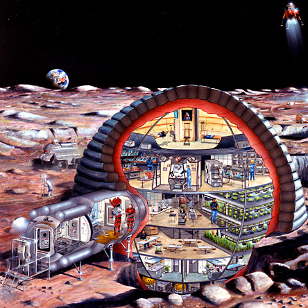
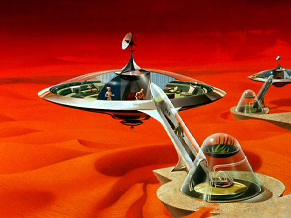
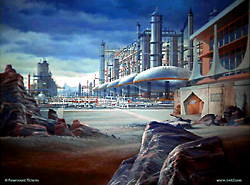
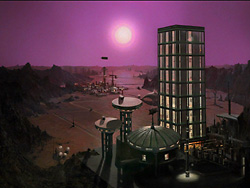
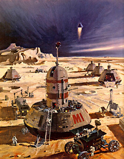
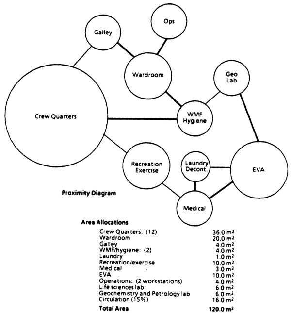

Abstract
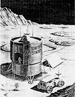
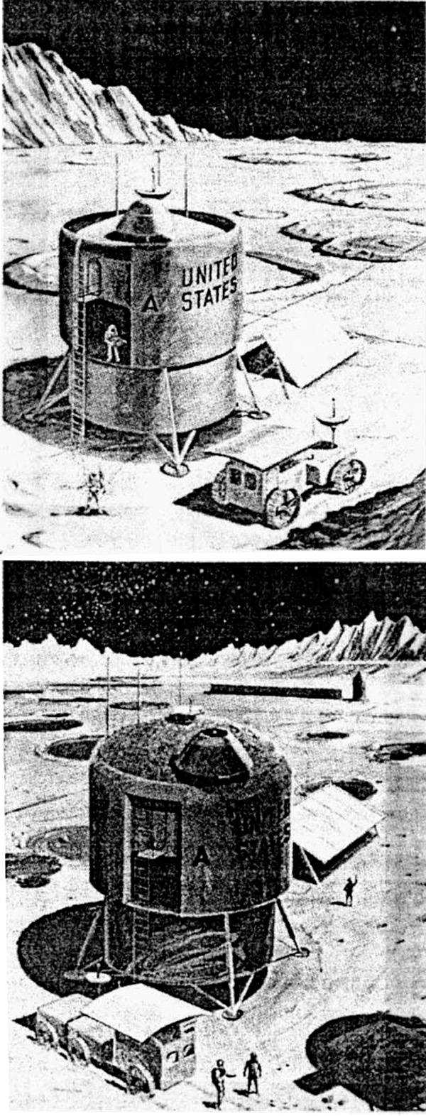
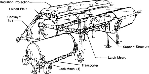
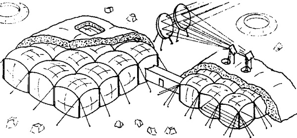
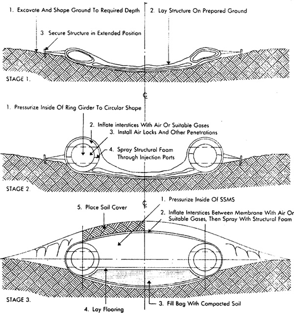
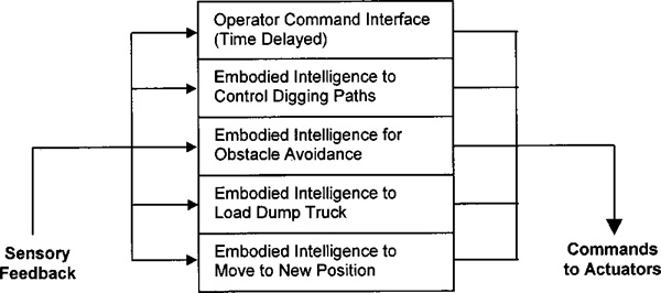
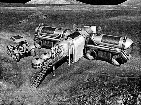
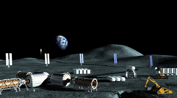
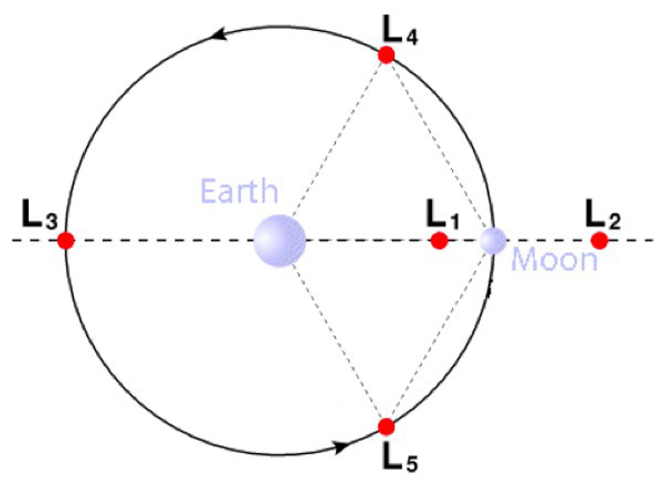
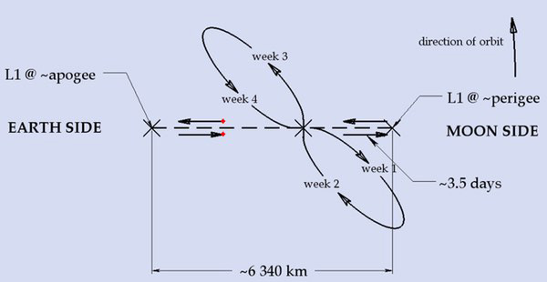
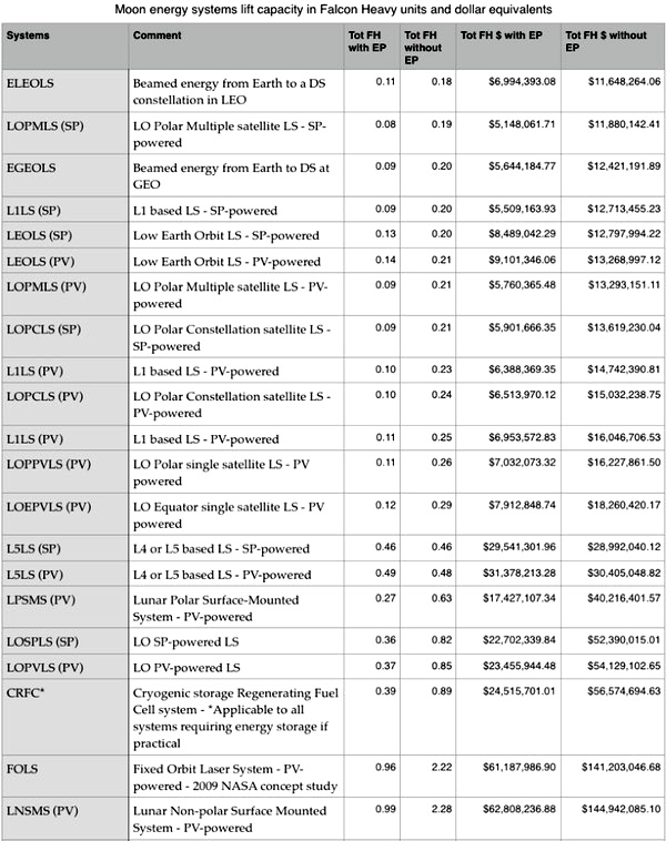
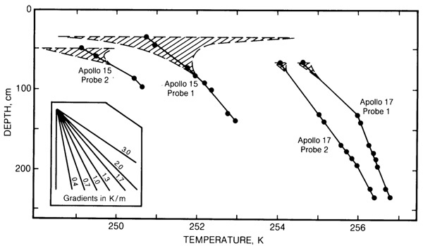


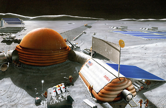
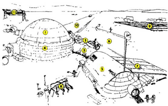
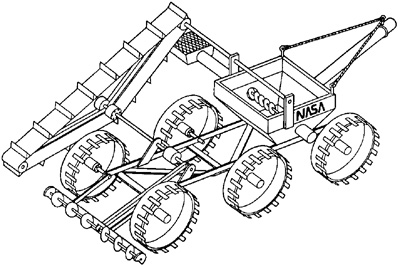
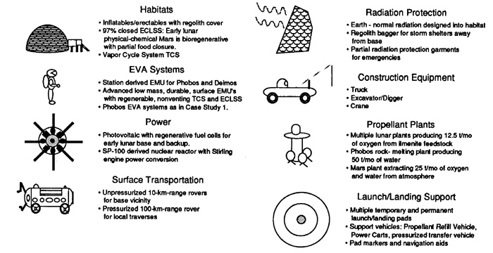
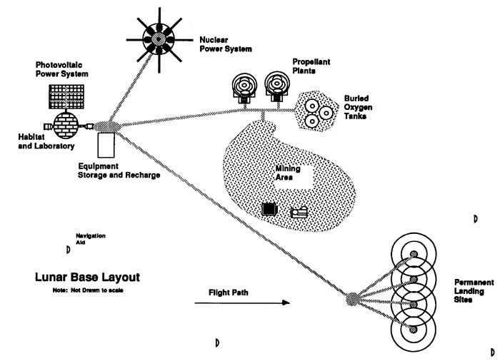
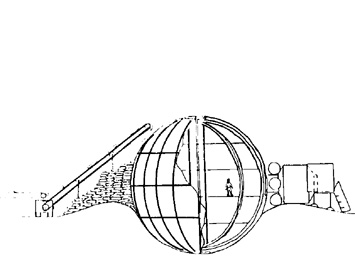
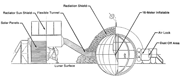
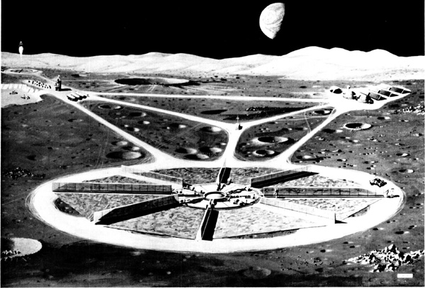
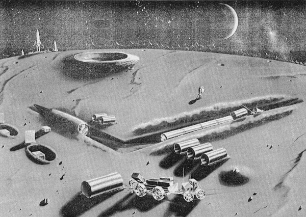
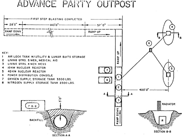
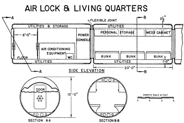
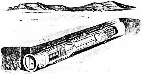
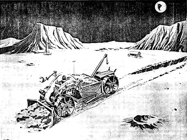
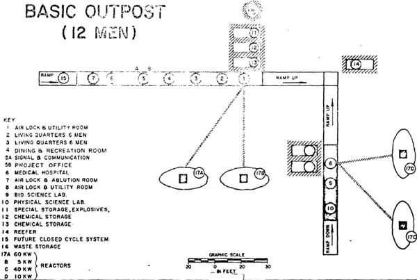
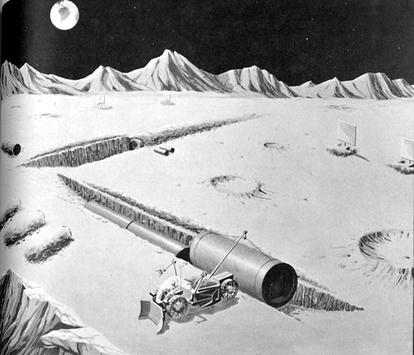
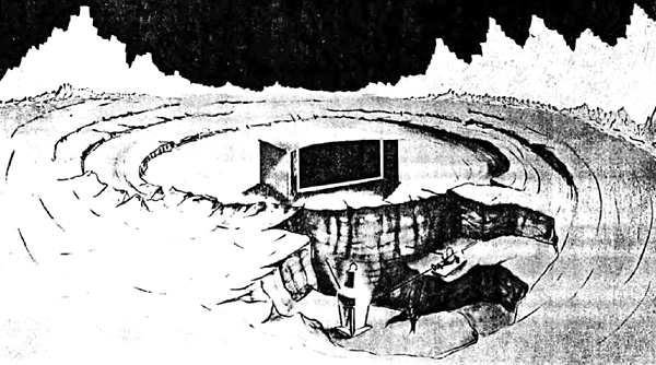
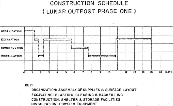
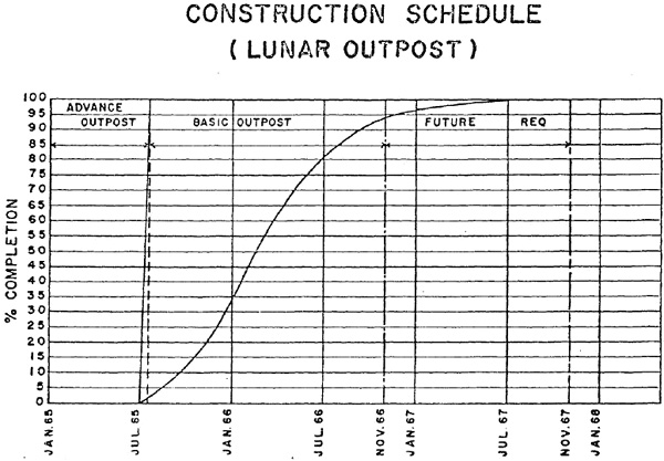
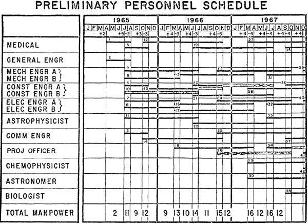
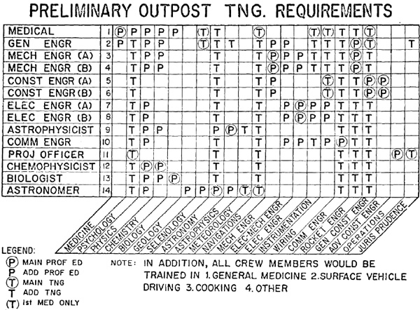
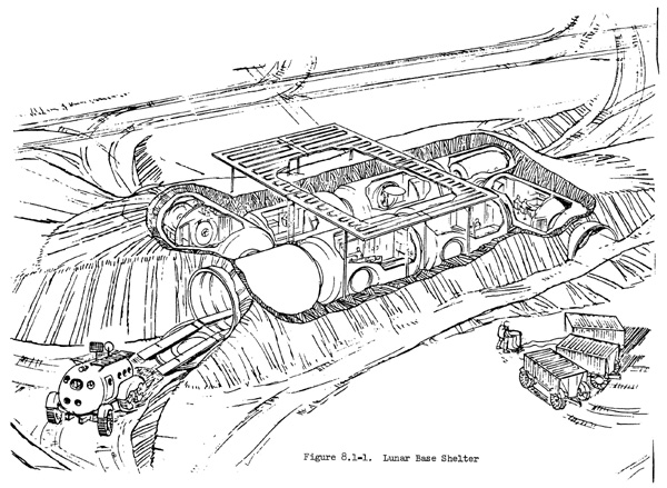


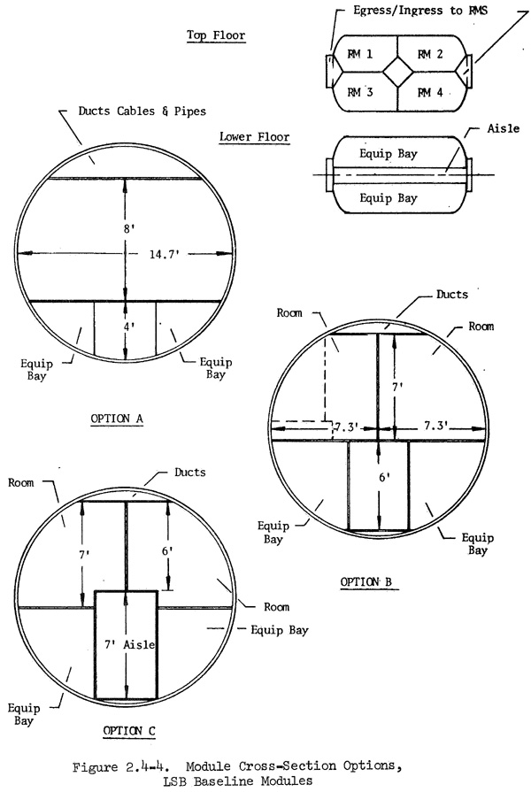
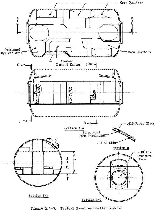
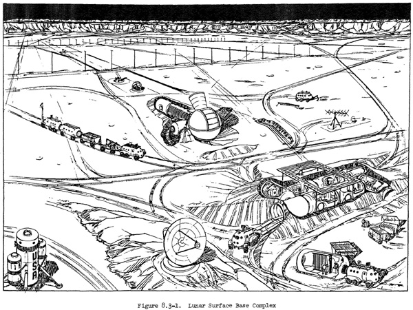


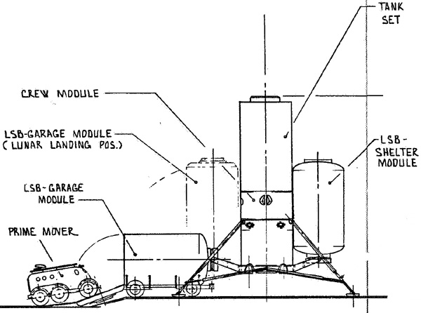
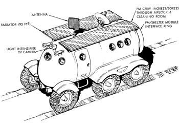
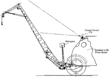
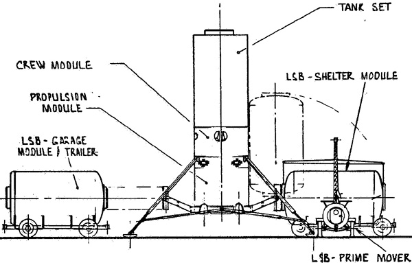


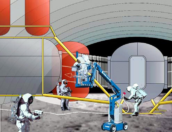
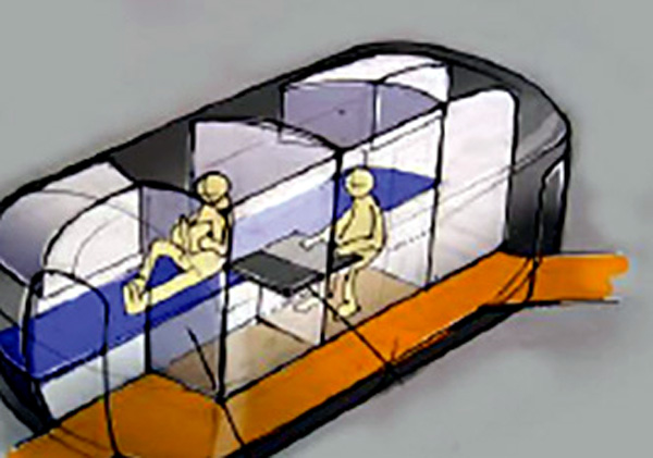
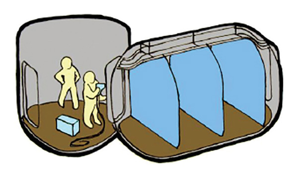
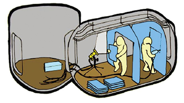
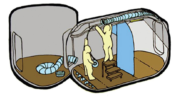
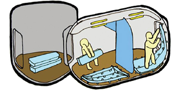
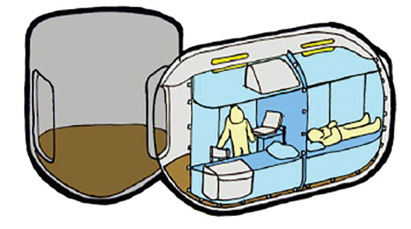
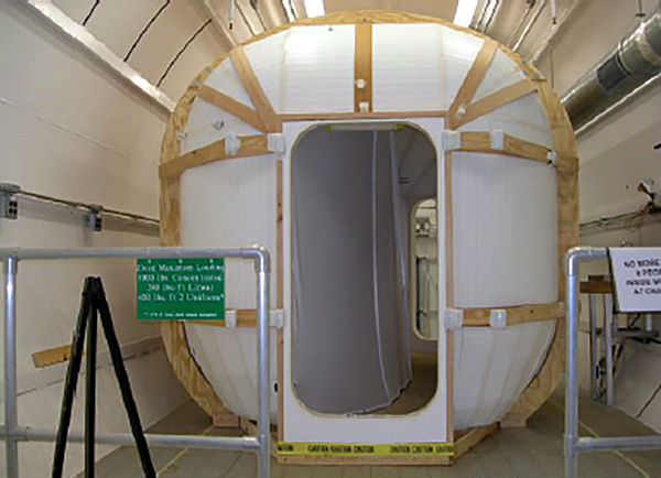
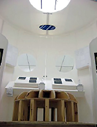
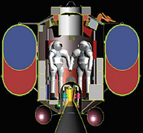

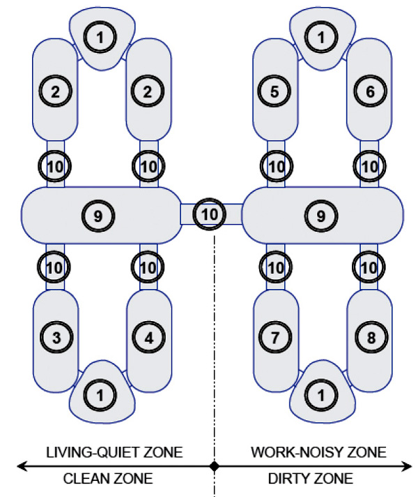
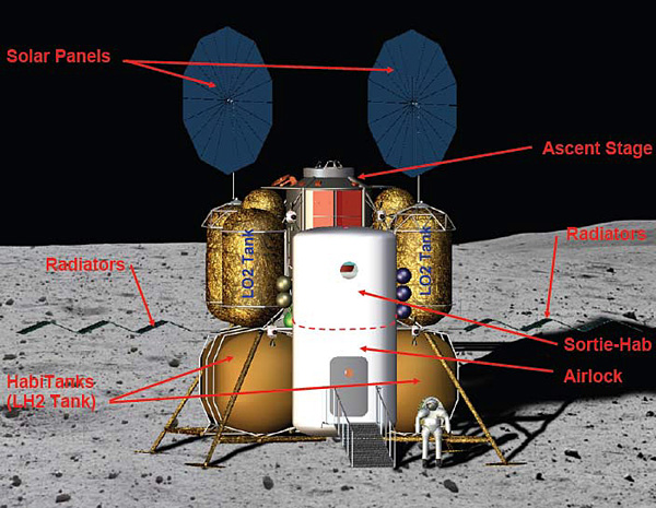
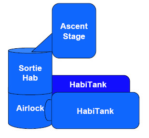


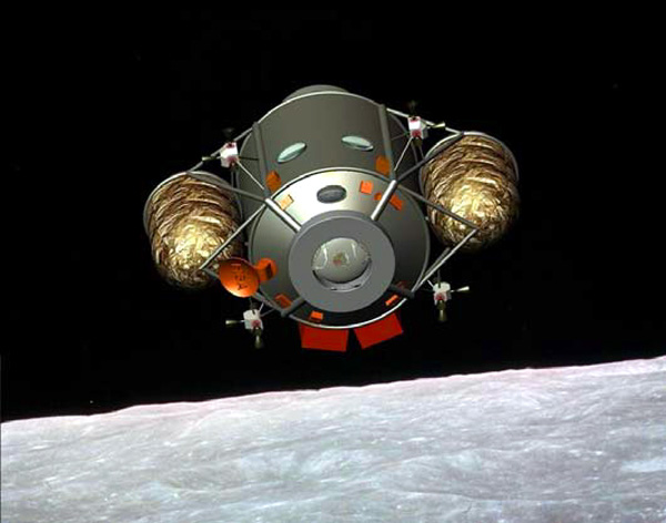


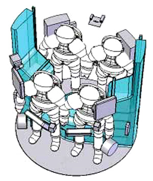
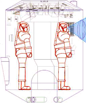
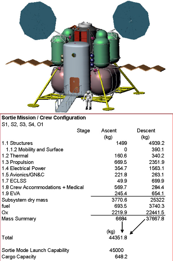
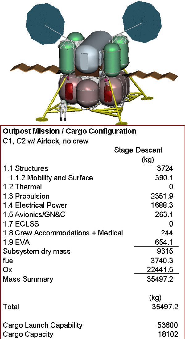
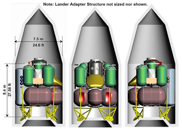
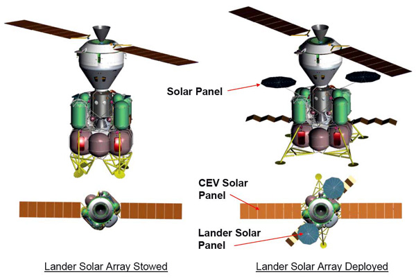

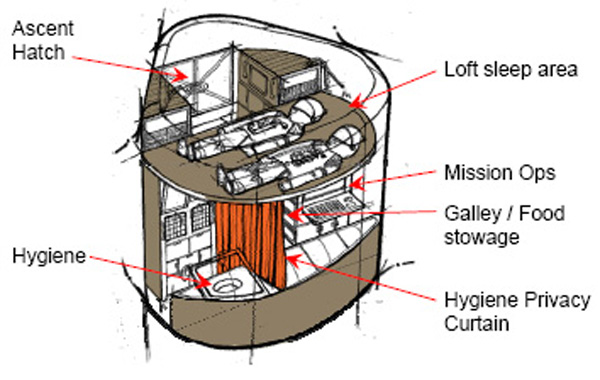
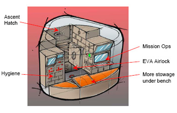
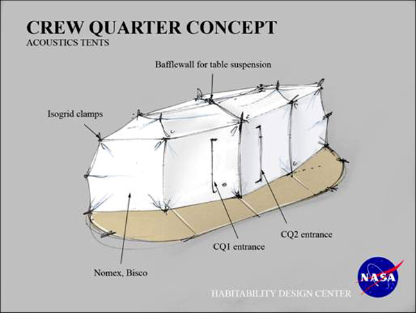
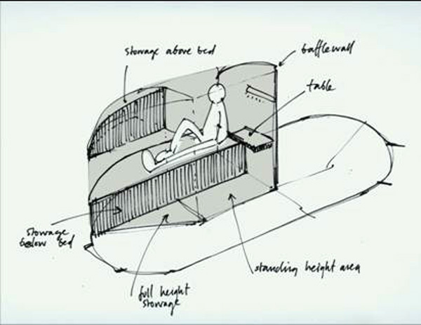
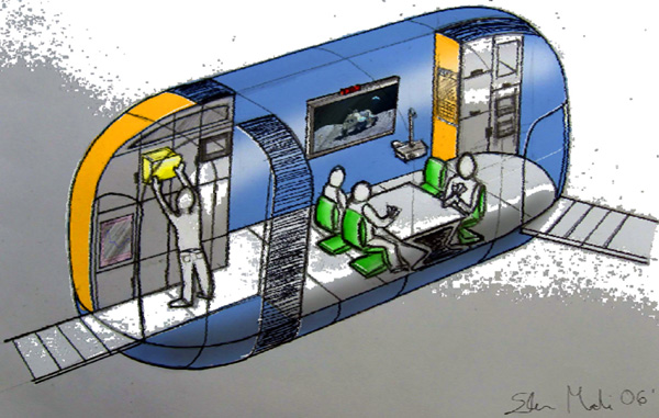
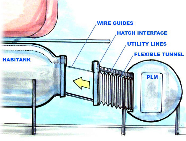
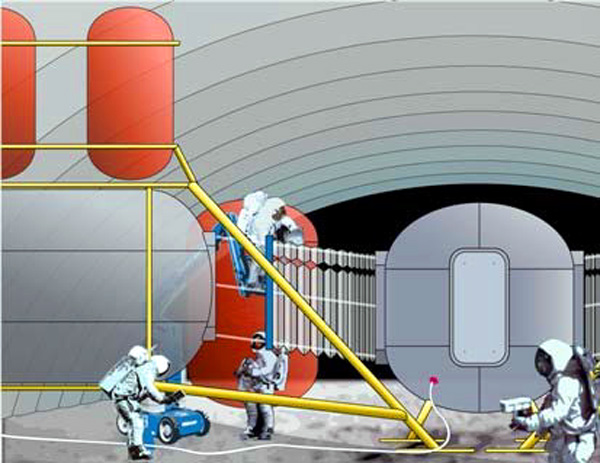
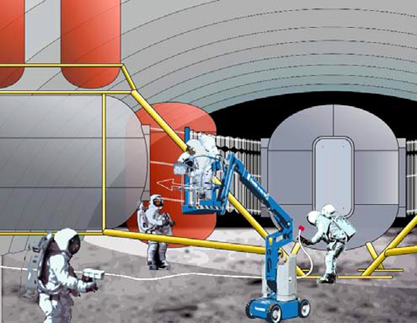

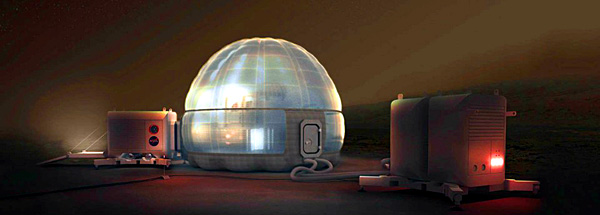


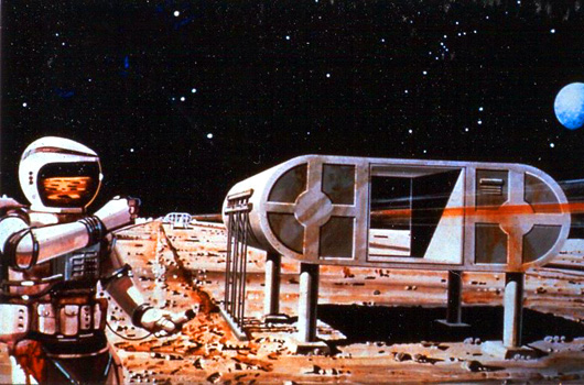

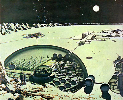
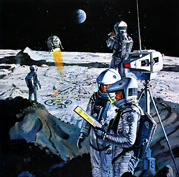
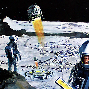
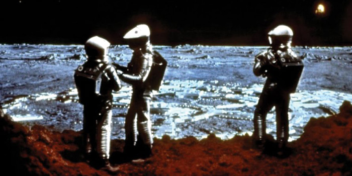
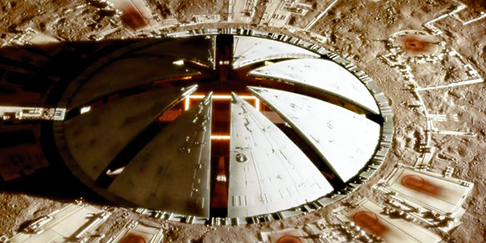
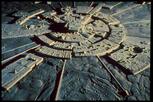
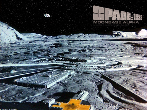
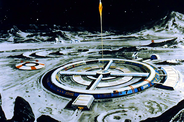


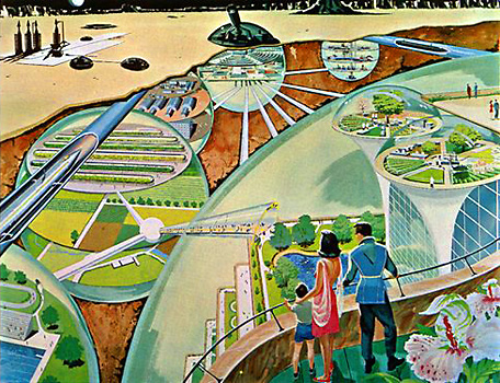


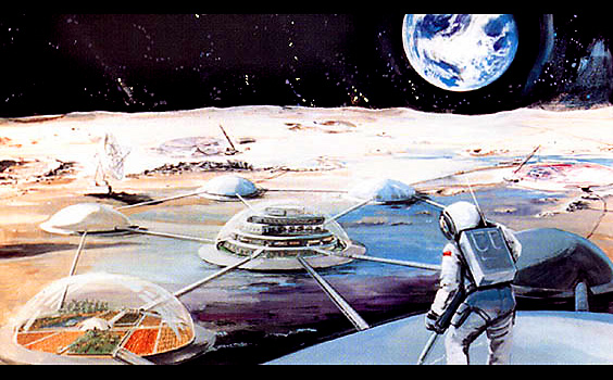
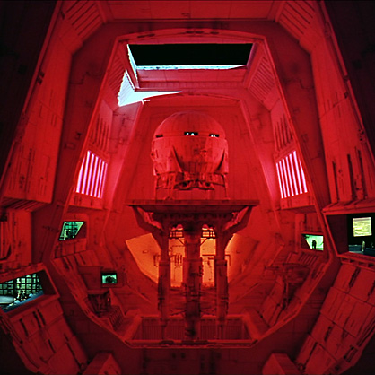
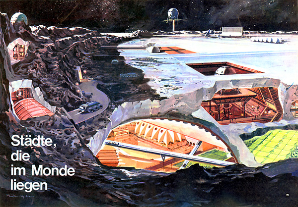
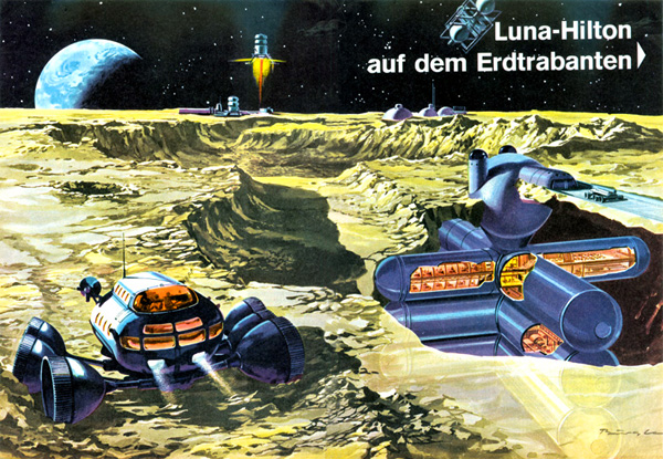
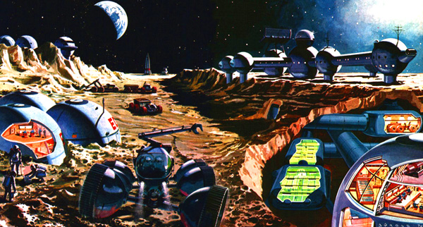
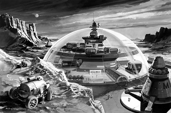
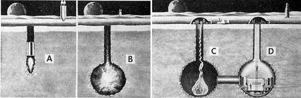
 From Modern Mechanics March 1962