These are some spacecraft designs that are based on reality. So they appear quite outlandish and undramatic looking. In the next page will appear designs that are fictional, but much more breathtaking. Obviously the spacecraft on this page are all NASA style exploration vehicles, they are not very suited for interplanetary combat (well, most of them at least).
Many of these spacecraft have a table of parameters. You can find the meaning of many of them here. Numbers in black are from the documents. Numbers in yellow have been calculated by me using the document numbers, these might be incorrect.
I'm toying with the idea of making some spacecraft "trading cards."
click for larger image
S.S. Absyrtis
ABSYRTIS
Propulsion
Fictional Thermo-catalyst
Isp
2,680 sec
Exhaust Velocity
26,300 m/s
Propellant mass flow
935 kg/sec
Thrust
2,500,000 kg 24,600,000 N
Inert mass
281,000 kg
Payload mass
56,000 kg
Dry mass
337,000 kg
Propellant mass
672,000 kg
Wet mass
1,013,000 kg
Mass Ratio
3.0
ΔV
28,900 m/s
Initial Accel
7.4 g (2.5 g?)
Burning time
720 seconds (12 minutes )
Optimum chamber temperature
3,450° C
Height
60 m
Maximum dia
6 m
Yes this is a fictional spacecraft, but it was designed by G. Harry Stine, former project engineer on the Viking and Aerobee rocket programs at White Sands Proving Ground. Mr. Stine used the Absyrtis in his novel CONTRABAND ROCKET written under the nom de plume "Lee Correy".
For purposes of the novel the Absyrtis needed a specific impulse higher than standard LOX/LH2(450 sec) but lower than a full blown nuclear thermal rocket engine. In time-honored fashion Mr. Stine created some handwavium out of his imagination. He postulated a catalyst propellant: but nuclear, not chemical. His "thermal-catalyst" fuel (aka "thermo-juice") is perfectly stable under normal conditions, but when subjected to a certain neutron flux the molecule explodes. The resultant high-velocity gas is further accelerated by neutron heating. Mr. Stine chose a specific impulse of 2,680 seconds, which is better than a closed-cycle gas core nuclear rocket but less than an open-cycle gas core.
I did some cross-checking on the performance numbers and they all seem to check out. Except I calculate an initial acceleration of only 2.5 g instead of the listed 7.4 g. No doubt I made a mistake in aritmetic.
I figure that the delta-V is about 29 km/sec, which is pretty good actually. Enough for a one-way orbit-to-orbit Hohmann transfer to pretty much anywhere in the solar system. Although many of those transfer will take more than a decade of transit time.
You can see a size comparison of the Absyrtis and other spacecraft here.
adapted from Spaceship Handbook, which has diagrams in far greater detail
Mr. Stine said the wings were inspired by a SM-62 Snark
CONTRABAND ROCKET
Note "Absyrtis" written on upper fin artwork by Ed Valigursky
(ed note: in the year 2050, our heros are members of the Southwestern Rocket Society (SRS) fan club. The fans want to travel in space in the worst way, but civilians are not allowed to fly in their own ships.
On a field trip to Luna Louis' rocket junkyard they are stunned to find the space ship Absyrtis sitting in the lot. As it turns out that ship was Mr. Louis' last command when he was in the UN Space Force, and when the ship was decommissioned he managed to obtain it at scrap metal prices.
Club president Chubb Delany has an insane idea. He tells Mr. Louis that the club would love to refurbish the old ship, and fly it on a short hop to Luna. With Mr. Louis as captain.
Mr. Louis says if the club will promise that, he will give the ship to them free, along with any used rocket parts in the lot needed for the refurbishing.)
UN Space Force interplanetary cruiser, missile launching, universal type, Argonaut Class
The space ship Absyrtis of the Argonaut Class
saw twenty-two years of service as a ship of the UN
Space Force line fleet, and an additional five years in
support and reserve capacity. She was a member of the
fleet which put down the Asgard Space Station Rebellion. After her modification to an express cargo vessel,
she was instrumental in the sustenance of the outposts
and colony on Venus. Subsequent modifications enabled
her to serve the Jovian moons. She operated as a support ship in the Titan expedition to Saturn, but
obsolescence forced her to confine her operations to the
Earth-Luna area in which she served in many capacities
until being mothballed and placed in circum-terrestrial
orbit. She was finally returned to White Sands Spaceport, sealed, decommissioned, and left to stand for two
years before being sold to a local salvage yard.
She was the first ship to bear the name and the
last of her class to be decommissioned and removed from
the Big Book. Her reliability earned for herself and her
crews three ratings of excellence, two efficiency awards,
a UN citation, numerous national commendations, and
the International Astronautical Federation plaque in
connection with her work in the Jovian moons area.
Manufacturer: Hueco Spacecraft Inc., White Sands Spaceport, America, Terra.
Commissioned: May 2018
“Have you, now?” Louis said quizzically. “And how do
you like the farce space flight is now?” “Farce?” Chubb echoed. “Farce, son. They’re too sloppy these days. It’s too easy.
Automatic controls. Nuclear drives. There was a time when
space flight was an art! Yes, sir An art! Not button pushing!
Used to load her up with thermo-propellants, hit the firing
button when the clock said so, and fly her by the seat of
your pants and the astrostat! All the time wondering if she
was going to blow! … That was space flight! Pilots, they
call themselves! Bah! Bus drivers is what they arel” He
settled back in his chair and jerked his thumb over his
shoulder. “Now, in the good old days, it was different. Take
the old Absyrtis back there on my lot …” The junk yard was old stuff to Chubb, but LeRoy was
utterly amazed at the terrific amounts of junk of all types.
As the old skipper led them out to where the Absyrtis
towered seventy meters over the low sheds, the real estate
man found himself making mental estimates of the combined
worth of this desert land and the tremendous inventory on
it. It was plain to see that Luna Louis was not a down-and-out old spacebum. “Captain, there seems to be a little
bit of everything here. How’d you come by it all?” “Ships are scrapped all the time, mate,” Louis replied. “Why? Do they wear out?” “No, sir! They just get obsolete,,and it becomes cheaper
to build a new ship than to modify the old one,” Luna
Louis explained. “The Bureau of Space Commerce has some
pretty strict rules about the condition of space craft; when
a ship reaches a certain age, they usually down-check it on
principle …” “How’s that?” “They figure it’s old enough that if something hasn’t
happened to it yet, it will. But with a little decent maintenance and repair, a space ship’s good for over a hundred
years … and a power plant’s good for a lot longer than
that because its operating time is only a fraction of that
of its ship.” Louis paused for a moment. “Of course, we
get a good deal of equipment from wrecked or damaged
ships. Got one lad who does nothing but sit up on the roof
with a pair of binoculars watching for ships that don’t make
the grade …” He let it drop at that because they had
reached the boat-tail of the Absyrtis. Chubb stopped to catch his breath and looked up. In
addition to the rust streaking her sides, there was no doubt
that this ship was old. The tall, slim, almost regal lines
were not those of a modern ship. Modern ships looked
efficient; they were. The Absyrtis was merely beautiful, a
work of art, the result of a designer with a sense of line and
sweep and proportion who had labored over his drawing
boards doing work which he must have loved. It was reflected starting from the parabola of revolution of her nose
cone down her sleek, unbroken sides to the graceful curve
of her boat-tail with its six gaping thrust chambers, and in
the swallow-like profile of her drooping wings. It belonged
to another day of space flight. “Shipped many a ton of lunar ore in this bucket,” Louis
said in recollection. “But she was a bitch to handle under
thrust. Shake? Man, she’d shake your teeth right out! And
the center of pressure would tend to wander forward of
the center of gravity if you didn’t watch the mass distribution. Let’s go aboard.” He grabbed a rope ladder hanging
down the side of the ship and clambered spryly aloft with
an agility which amazed Chubb and LeRoy. LeRoy followed and Chubb waited until the other had
gained the lock high on the ship before he entrusted his
full weight to the ropes. He didn’t look down; if he had,
he would have frozen to the ladder with vertigo. He kept
his eyes aloft and climbed steadily, hand-foot-hand-foot.
He was out of breath when he stepped through the air
lock and looked around. The tour of the old ship was fascinating. Chubb’s eyes
were alight the entire time. It was like a childhood dream
come true. It brought up memories entombed by the years
and Chubb remembered the toy spaceships which looked
like the Absyrtis and the drawings he had hopefully sent
to the Space Force at White Sands, crude sketches of a
“Sooper Space Combat Rocket”. And there were forgotten
memories of a chubby little boy playing spaceman in that
pile of boxes in the back yard, dreaming of a space ship
the image of which was the Absyrtis. Just being in her gave him a feeling of satisfaction he had
not experienced for years. Feeling the cold metal of her
companionways and smelling the ancient, musty odors of
far-off worlds which still lingered in her made him suddenly realize with a pang of sorrow and regret that this could
have been his—could have, if he had had a different gene
makeup (Chubb's genetic makeup predisposes him to be overweight, not allowed in space crews). The Absyrtis was far from a complete space ship. Most
of the power plant essentials were missing, the electronics
had been stripped, and there were no astrogation instruments. The Absyrtis had seen hand tools, but not a cutting
torch. “Give her just a few essentials and she’s ready to lift,”
Louis remarked, sitting down on an acceleration couch
in the barren, echoing control room far forward in the nose.
“Many’s the time I’ve sweated it out on this couch, mates.
But this old bucket never failed me. A taut, reliable old
ship she was. After we converted her to thermo-juice, she
saw Mars and Venus and Ganymede. Bailey took her out
to Titan once after I got stuck on dirt for keeps. But she
knows her way into Dianaport by heart; hardly have to lay
a finger on the board for a landing. She just sniffs her way
in.” “What are you going to do with her, skipper?” Chubb
ventured to ask. “She’s the last of her kind, mate. The pure-nuclear ships
have taken over now. And a new kind of spaceman is flying
them. We’re both obsolete, so she stays here with me. Oh,
maybe one of these days I’ll get me a red-hot crew together. We may not get high enough to crash, but we’ll
still get oft the ground again. The regulation hounds will
try to stop us, but to hell with them! It’s a sad thing, mates,
when the laws won’t let a man do what he wants or even kill
himself as long as he doesn’t hurt anybody else in the
process.” The old man’s eyes were on the empty holes in
the control panels where instruments, lights, and switches
should have been.
(ed note: Mr. Louis takes them up on their offer. In exchange for refurbishing the Absyrtis and keeping Louis as captain, he will give them the ship for free)
Refitting the Absyrtis turned out to be quite a task. The
old ship lacked more than was apparent on a cursory inspection. As a result, Chubb closed the doors to his consulting office in order to devote his full energies to the
project. So he moved in with Luna Louis, sharing the old bachelor’s quarters with him. It was far from being luxurious, but
Chubb was having the time of his life. He didn’t really
care where he slept or when he ate; he had his hands on a
space ship at last. Louis turned out to be less senile than any of them expected. He seemed to snap out of his dreamy moods. The
transition was strange to behold. Once again, he stood
straight and his voice carried the tone of authority and
casual competence. His eyes became alert, and his mind
sharpened like a rusty knife edge that has been put to the
whetstone at long last. The youngsters of the SRS were by far the most persistent at the work site. They came in droves on Friday afternoon and stayed on the job until Monday morning when
they dragged back across the desert to classes or to their
jobs. Many of them came out during the week to perform
the many tasks at hand. Their first job was a complete and minute inspection of
the ship as she stood. No manuals on the Argonaut Class
could be found, but Luna Louis turned out to be a man of
remarkable memory. “Hey, skipper, this valve seat mikes a tenth of a millimeter less than the blade. What gives here?” LeRoy called
from the power room on the temporary intercom Bert Eggstrom had rigged. Louis answered from the forward radar blister, “Where
did it come from?” “The feed heater just abaft of the forward tank bay.” “That sounds about right, Mister Finch. What’s the condition of the seat and gland packing?” “Packing’s shot. But how can this valve seal?” “Don’t worry about it. It gets hot in that forward feed
heater. Thermal expansion of the seat causes that valve to
seal tighter than your old britches. Get the part number
off that valve, and we’ll see if maybe I’ve got some packing
for it. Pull the whole valve and take it down to the shop.” “Right-o, skipper!” “Hey, skipper?” Chubb’s voce echoed up the main ship
well. “Got a minute?” Louis turned to the youngster who was working in the
blister with him. “Yank that sweep selsyn, Jimmy. The
rotor’s shot. I think maybe one of the units from that old
Mark Fourteen radar out in the yard will fit. Don’t bother
with those cap screws; knock it loose with a hammer, because you’ll have to drill and tap new holes anyway." “How about these waveguide junctions, skipper?” “Put the torque wrench to them. They’ll warp back,”
the old skipper told him, handing him his tools and crawling
out of the little hatch into the main portion of the ship.
Wiping the sweat from his neck with a piece of waste, he
yelled down the well, “Up here, mate!” Chubb came puffing up the ladder from below. “Here’s
a survey of the equipment in the boat-tail, skipper.” Leafing slowly through the sheaf of papers handed to
him, Louis mused, “Not as bad as I expected.” “What do you mean, skipper? Half the structural members back there are bent, broken, or missing! Engineering-wise, it’s flimsy as a paper bag!” “And just what do you know about space ship structures,
Mister Delany?” Louis asked sarcastically. “The tail of this
bucket was grossly over-designed. We ripped out those
members years ago to make room for the thermo-juice
drive.” He handed the papers back to Chubb and told him,
“Take them down and give them to that gal who’s doing the
consolidation. I’ve got most of these missing parts—or something that will do the job.” “Check, skipper. Tank bays and radars are the only lists
we need now. Maybe we’d better start thinking about moving the ship out to a launching pad.” “Why move her?” “Huh?” “A fine “engineer you are! What would the costs be? I've
got the parts, the shops, and the tools right here.” Chubb thought about this. “You mean refit and lift from
here?” “Is there a better place?” “But it’ll wreck your yard when we lift, skipper.” “So it will. But once we raise ship, mate, I’ll not be
needing this yard any longer.” Chubb stared at him for a moment, then quietly went
out the hatch and clambered down the hastily-rigged servicing tower. A month ago, he would have paled at the
thought of hanging on a slender ladder fifty meters up. He
had in fact done so. But it didn’t bother him now, and he
was in much better physical shape. It was a matter of pride
to him that he had managed to lose five kilos. Wandering back through the yard toward the hut they
were using for an office, he noticed the change in Luna
Louis’ junk yard. Old tools had been ressurected from the
heaps, cleaned up, and placed in sheds. Under a ragged tarpoline, three youths were hydrostating valves and pressure
vessels; beside them was a jury-rigged flow bench. Farther
down the line, he passed a leaning shack in which Bert and
several other men were working over old radar gear. A sign
over the door proudly announced, “Department of Witchcraft and Sorcery. Slightly Used Pentacles and Klystrons
For Sale.”
artwork by G. Benvenuti
It took five long months filled with scrounging for old
parts, digging around in junk yards all over North America,
and draining of funds. Chubb’s savings were long gone.
Luna Louis had converted everything he could to cash. Al
Olson, being independently wealthy, kept the project on
its feet. Everybody worked their hearts out. There were long
hours. There were the inevitable minor accidents. There
were daily crises which threatened to wreck the whole
thing. Louis had his hands more that full working with a
very green crew. Everybody made mistakes—but nobody
made the same one twice. But the day finally arrived when
they could start making dry runs of the ship and her equipment. The old Absyrtis didn’t look the same at all, Sporting a
new coat of brown and yellow paint—a purposely difierent
color and marking scheme than that used anywhere else
—she was practically a new ship inside and out. Chubb stood surveying her in the late afternoon sunlight, taking a break in his schedule for a cigarette. Yes,
every one of the hundreds of men and boys who had worked
on her could take real pride in her now, he knew. A few
more checks, radioactive bricks for her reactor, and propellants were all she needed—plus a trained crew. Olson was out pulling the legal strings for the reactor
bricks. Chubb had no idea how they were going to be
pried loose from the Bureaus of Nuclear Energy, but Al
had assured him that there would be no trouble. The propellants? Well, Chubb was expecting ten tank
cars into El Paso any day. There was no problem there.
The “go-juice” for which the Absyrtis had been designed
was a commercially-available chemical which would release
its energy by thermo-catalytic action. It was cheap, but it
was no longer used for space flight. The rocket engine is a basically useful device. Rocket
engineers found this out many, many years before when
they became aware that the military subsidies following the
Second World War might not last forever. A rocket can do
more than push. It can generate tremendous volumes of
gas. It is an essential device for high-speed, high-temperature chemistry. And the jet of hot gases man dig holes. In
the open-pit copper and iron mines all over the world, the
snarl of rocket engines was a common thing as their exhausts dug holes faster and more economically than the
best carbide bits. The crew was his only real worry. He knew they were
still green as grass, himself included. Space Commander
McLaughlin had been right on one point: you don’t learn
it all out of the books. Some people had picked up Louis’
training with little effort; others just couldn’t understand
the difference between a fitting and a flange or between a
selsyn and a klystron, no matter how high their enthusiasm had been. “All hands clear the ship!” Louis’ voice came from a
portable megaphone from the lock high on the side of the
ship. “Stand clear for pressurizing and water-flow checks!” Chubb was joined by Bert, who was handling the electronics and had no part in this check of the propulsion system. “Ran the final checks on the radar today, Chubb. That
doppler system is all hot to go. Same with the guidance
and control.” “Good! Did you get the running rabbits off the surveilance screens?” “Yeah, found a mis-matched waveguide in the antenna
system. How’s Greg doing with the air system?” “Had chlorogel all over Deck D the last I saw him,”
Chuhb replied. “Sprung a leak in the irradiation chambers.” “Tough luck.” “He’ll get it fixed. He’s good.” Chubb watched the silent
ship for a moment, then asked, “Say, Bert, maybe it’s none
of my business, but how come a sharp electronic engineer
like you never got into space in the first place?” “Oh,” Bert said offhandedly, “eyes for one thing. Plus
the fact I’m a lunger.” “T-B? You don’t look like it!” “Hell, man, I’ve only got one lung—and that’s full of
calcification. Why do you think I came to this country?
Same reason as Greg: climate.” Great space! Chubb thought. What a crew this ship’s got!
Greg with arthritis, Bert with one lung, LeRoy with a heart,
and the skipper ripe for the grave! And me, twenty kilos
overweight! “Stand by to pressurize!” came the call from the ship.
Through the thick hull of the Absyrtis the two men on the
ground heard the slam of valves and the high-pitched, ringing hiss of pressurized gas filling the propellant tanks. Nothing ruptured; the tanks held their pressure. “What are they doing?” Bert wanted to know. “We’ve got a dummy propellant load of water in the
tanks,” Chuhb explained, rocking back on his heels with
his arms on his hips. “They’ve pressurized to detect leaks
and to see if the system will hold pressure. Next they’ll pop
the main propellant valves and run the water out through
the rocket nozzles to check flow rates and pressure drops.” “How can they run the propellant pumps without the
reactor to drive them?” “They won't need the pumps. LeRoy and the skipper
just want flow characteristics. They know what effect the
pumps will have and they … Hold it! There they go!” It was quite a show. A terrific roar came from the stem
of the ship, but no flame lashed out. Instead, the rocket
nozzles sprayed solid streams of water which ran off onto the
desert sands in a small flood. Thousand of gallons of water
spewed out before the flood suddenly ceased with a bang
and a hammering sound. “Wow! I’ll bet that shut-down opened a dozen joints!”
Chubb took off across the desert like a huge ballon being
driven before a gale. The power room was a mess when he climbed into it.
LeRoy and his crew were trying to tighten fittings and stem
the gush of water. There was still considerable water remaining in the tanks. Everybody was soaking wet. Chubb
grabbed a box wrench, snugged up a leaking fitting, and
shouted to LeRoy “Vents open?” “Hell, yes! Get that flange tight before we drown!” “Open your dump valves and drain those tanks! You’ll
never get these fitting tight with ten meters of hydraulic
head on them” LeRoy leaped for the jetman’s couch and threw switches.
“Electrical system’s shorted out by water! Open that hand
valve next to you, Chubb!” Once the situation was under control, Chubb—looking
like a water-loogged whale—sat down on an auxiliary generator and observed. “I thought you guys knew this power
room. What a sad show! What would you have done in a
real emergency?”
(ed note: A torrential thunderstorm undermines the landing pad andthe ship tips. The ship is saved, but...)
The Absyrtis was canted over at a five-degree angle, and
that was that. Chubb and Luna Louis surveyed the situation
the next morning and came to the conclusion that any
attempt to right the ship might cause her to fall even
farther. The only answer was to secure the ship in its
present position and proceed. Taking LeRoy’s suggestion,
they fastened quick-release clamps on the guys, then
promptly safetied them against accidental release. The rest of the check-outs on the “Leaning Tower of
White Sands”—the name hung on the ship by Greg Shearer
—went off more or less as scheduled. They weren’t all successful at first. Bert Eggstrom was the only one who didn’t
have more than his share of troubles, but he had them nonetheless. The communication gear worked like a charm, and
Bert was very proud the night he logged his first contact
with Asgard Space Station as it went over. The computer
and the autopilot finally made four consecutively successful
dry runs. He had trouble with the radar; instead of tracking the high-flying evening antipodal rocket as intended,
it locked onto a flight of ducks migrating south. But it
tracked. LeRoy kept on finding leaks, sticky valves, broken welds,
and loose nuts everywhere. Most of his trouble was with
a very green crew. The college students working for him
did extremely well, but he had trouble with other kinds
of people. Imagine trying to teach a dry-goods salesman how
to run a smooth weld. Greg Shearer was having trouble with the air system, the
water recovery system, and the hatches and locks. Being
a bachelor like Chubb, he didn’t have the same kind of
trouble LeRoy was having, but he had trouble enough
nonetheless. He had recruited every member of the SRS who would
work and who had, like himself, a green thumb and a
knowledge of organic and catalytic chemistry. On the first
pressure test, gaskets leaked all over the place, but the worst
part came when Greg replaced the standard air with the
oxy-helium space mix from the air system. It drove everybody choking from the ship. The ship air from the blowers
smelled something like a cross between a garbage dump,
a stable, and a locker room. In disgust, he and his crew
had to replace every bit of chlorogel solution in the system—while wearing respirators. In addition, the ship’s water came out a putrid brown for
five days while he fiddled with the old and finnicky water
recovery system. He was still working with it when Luna Louis came
around with Chubb for a final inspection on the refitting.
Louis inspected the ship with a critical eye, finding things
that nobody expected. He suggested here, corrected there,
bawled out ninety-percent of the crew for blunders and
oversights, but finally pronounced the ship as ready as it
ever would be for final checks, provisioning, and space. It should have been a day of rejoicing, but for Chubb it
was one of anxiety. During the quiet evening hours after
supper when everybody sat around listening to Luna Louis
spin old space tales of faraway worlds, Chubb could not
keep his mind off the subject. The final check of the ship would require that the reactor be activated. This meant heavy water(moderator) and thorium,
and as far as he was concerned that might take an act
of God to get. The Bureau of Nuclear Power didn’t pass
that kind of stuff around like tin pennies. They went in the personnel hatch. The interior of the
ship was considerably different than it had been the day
they had first walked her decks. New paint glistened on
the bulkheads, and the smell of oil and solvents and men
was in her again. After going up the main ship well, they
emerged into the control room. The new pastahide cushions
on the couches shone in the light of the resurrected flouro-units, and the gaping holes in the panels had been filled
with instruments, gauges, switches, and winking lights.
The computer rack now held a small electronic brain
which was capable of flying the ship; Bert had managed
to pick it up from Space Force surplus and had rebuilt it.
It was capable of reading-in data in any number of ways:
from sensing elements in the ship, from ground radio commands, from control panel commands, and from a self-programming keyboard. Its read-out was equally as versatile. Bert regarded it as being several grades smarter than
any of the SRS men working on the ship. “About time you showed up,” Louis remarked caustically.
“Grab a cup of joe and sit down. You might favor me by
pouring me another cup while you’re at it. Can’t operate
without coffee.” Luna Louis, true to Space Force tradition,
had set up three indispensable things immediately on the
Absyrtis; in order they were a coffee mess, a loudspeaker
system, and a wardroom of division officers who really ran
things. “It has to be that way, Mister Olson,” Louis pointed
out. He took a long swig of coffee and went on, “And now
we have a slight logistics problem: thorium and heavy
water. What do you have to report on that, Mister Olson?” “It’s on its way. Be here tomorrow.” Chubb sat up and knocked his head against the bottom
of the couch above. “Along with the BSC boys who will
promptly hang a red tag on the lock?” Al Olson smiled knowingly. “Not yet. It seems the UN
once passed a Nuclear Energy Act which has been on the
books since 2005. It guarantees the delivery of available
radioactive substances to non-profit organizations utilizing
it for other than commercial purposes. After a little talk
with the BNP (Bureau of Nuclear Power) Regional Director in Albuquerque, the way
was paved.” “What did it cost?” Bert wanted to know. “It’s still BNP property under consignment lease to us,”
Al replied. Luna Louis had to supervise the installation of the
thorium and heavy water. The current BNP manuals possessed by the two men did not include the procedure for
the Argonaut Class, the reactor being a long-obsolete model.
This caused Chubb to ask Louis anxiously, “Skipper, are
you sure this old reactor has enough soup to lift this ship?” “Mate,” Louis said huffily, “if the engineers hadn’t decided to go to the pure nuclear drive, they’d still be using
this type of reactor. This old Mark Seven’s a damn-sight
more reliable and efiicient per kilogram of mass and has a
lower operating count so the ship shielding is lighter. What
licked this type of drive years ago was the propellant mass
you have to carry … and thermo-juice was more expensive then. The nuclear stuff cost less when they changed
over, but this bucket’s flown for twenty years with that
fish bowl, and it hasn’t had so much as a pin-hole leak in
the heat exchanger. The Baja California power pile can't
boast that record, mate!” At last, they were ready for the final checks. LeBoy, who
had hand-picked his engineering gang, treated the reactor
with a great deal of respect now. The power crew started
using the particle counters which had been racked at the
ready on the power room bulkhead for months. They raised
the temperature to a stable plateau capable of running the
ship’s generators and of charging the batteries, although
ground power was still available to help them out. The
other divisions began a gradual phase-over to reactor power
but only as an emergency measure.
Aerojet Rocketdyne has been studying manned Mars missions using spacecraft propelled by solid-core nuclear thermal propulsion (NTP) using low-enriched uranium (LEU). They are using LEU because the military and the International Atomic Energy Agency gets very paranoid about civilians getting their hands on uranium that is anywhere near weapons-grade. Specifically Aerojet Rocketdyne wants to work with High-assay low-enriched uranium (HALEU). LEU is enriched from 2% to 20%, most commercial reactors use enriched from 2% to 5%, HALEU is enriched from 5% to 20%. There had been some other NTP proposals from other companies using HEU, but those proposals had been shelved due to said paranoia.
By using HALEU, Aerojet hopes to design an engine with a specific impulse above 900 seconds (exhaust velocity above 8,800 m/s), which is an improvement over chemical rocket's pathetic 450 seconds (The BWXT company is looking into 19.75% enriched HALEU as well). Aerojet has been working on this for a couple of decades, patiently altering the ground rules to accomodate curve balls thrown by NASA (the most recent being structuring the mission around NASA's questionable Lunar "Gateway"aka the Lunar Operations Platform-Gateway or LOP-G).
Aerojet figures that their engine has a variety of applications:
Moving heavy cargo (e.g., large landers) to Mars within 200 days
Delivering larger orbiter spacecraft to Jupiter (e.g., two to three times the size of Juno)
Delivering orbiters (as opposed to a mere fly-by) the size of New Horizons or larger at the outer planets with transit times less than ten years
Fly-by space probe missions to the outer planets using just the LEU NTP core stage flown directly from the faring of the Space Launch System(if the SLS ever sees the light of day), without needing multiple launches and space assembly of a full LEU NTP spacecraft
The LEU Nuclear Thermal Propulsion System
Aerojet goal was to optimise the engine for:
Maximum possible specific impulse
Minimum possible reactor mass
Longest operating life of nuclear criticality, meaning maximum number of hours of thrust you can get out of the engine before the blasted thing clogs up with nuclear poisons and stops working.
FIGURE 1. A Schematic of a NTP Engine System with LEU UN Fuel Elements – 25,000-lbf(111,200 N) Thrust Class.
Figure 2: NTP Mars Transfer Vehicle Concept Update with 3 x 25,000 lbf NTP Engines.
Both Aerojet and NASA have done numerous studies that suggest for a crewed Mars mission, the optimum propulsion system is an array of three NTP engines with a thrust of 25,000 lbf each (111,200 N) for a total thrust of 75,000 lbf(333,600 N). Each engine has a reactor with a thermal power of 550 MWt which heats the propellant to greater than 2,600 K for a specific impulse of 890 seconds or greater (exhaust velocity of 8,700 m/s or greater). Each reactor will require 50 to 100 kilograms of LEU. A single engine is comparable in size to a standard chemical RL10B-2 engine.
LEU NTP Mission Trade Studies
Aerojet wants to assure the reader that they have been continually doing trade studies on Mars Mission spacecraft using this system since 2016. Because NASA has made the requirements a freaking moving target. First the study using NASA's initial ground rules, then a new study when NASA updated to the Evolvable Mars Campaign (EMC) in 2016, and then yet another new study when NASA incorporated the information from the Mars Capability Studies (MSC) team in 2018 (“In-Space Transportation for NASA’s Evolvable Mars Campaign”, and “Transit habitat Design for Mars Exploration”). The LEU NTP had many advantages:
the spacecraft mass can be reduced by using cis-lunar aggregation Near-rectilinear halo orbit (NRHO) orbit (coincidentally the orbit of the NASA Lunar Gateway, surprise surprise) and a lunar-distant high-Earth-orbit (LD-HEO) type orbit for Terra departure and return.
using the above orbits still allows a transit time from Terra to Mars of five to six months
the spacecraft can be boosted into orbit piecemeal in as little as four or five SLS launches using the 8.4m payload faring
However, the priority was to reduce the Terra to Mars to Terra transit times. Because the longer the trip, the more radiation exposure suffered by the crew due to deadly Galactic Cosmic Rays. It is impractical to carry enough radiation shielding for full protection (meaning the a viable spacecraft might be impossible to design), so the fallback position is to reduce expsure time.
In Figure 4 below, the Low Thrust (LT) option is a conventional solar-powered ion drive rocket while the High Thrust (HT) option is the LEU NTP rocket. As you can see the LEU NTP rocket has a drastically reduced radiation expose in all its options.
Figure 4: Mars Crew GCR Dose Rate Reduction with High Thrust NTP.
Low Thrust = Solar Electric Propulsion (ion drive)
High Thrust = NTP engines
Back in 1962, NASA's Marshall Space Flight Center's Future Projects Office (FPO) decided to get serious about manned exploration of other planets. They commissioned a study with the contrived name Early Manned Planetary-Interplanetary Roundtrip Expeditions (EMPIRE). Three mission study contracts were awarded. General Dynamics would study Mars orbital missions. Lockheed would study Mars flyby and orbital missions. And Aeronutronic would study Mars-Venus flybys.
Doing a flyby instead of a landing was disappointing, but the FPO figured you need to start with baby steps. A flyby would require less than half the delta V of a full blown Mars orbital or landing mission. Nowadays we would wonder why bother to send astronauts when you could just use an unmanned space probe. However, back in the 1960s automated probes were nowhere near reliable enough for such a mission.
As a consolation the studies were allowed to include NERVA nuclear thermal rockets. A mission to Mars using honest-to-jonny atomic rockets, by Jove!
Aeronutronic examined the work of Dr. Gaetano Crocco. In 1956 he published a mission that would require only one burn to inject the spacecraft into the mission trajectory, it would coast for the rest of the mission. The spacecraft would do a flyby reconnaissance of Mars and arrive back at Terra exactly one year to the day (so Terra would be back at the starting point). All with no additional engine burns. Naturally the spacecraft will need an additional 13.5 km/sec delta V in order to brake into Terran capture and landing, but this can be done without fuel by using aerobraking. This mission was called the Unperturbed Non-Symmetrical Trajectory which was immediately shortened to the Crocco Trajectory.
The astronauts would observe Mars through telescopes during the brief flyby. Annoyingly, if the ship came closer to Mars than about 1,300,000 kilometers, the gravity well would bend the trajectory such that the ship would miss Terra and the astronauts would die a lonely death in deep space. After going to all this trouble for a Mars space mission it is frustrating to be prevented from getting any closer than three times the Terra-Luna distance.
Dr. Crocco had a solution. The ship could get closer to Mars. As long as the trajectory was designed so that the spacecraft did a bank-shot off of Venus' gravity well to correct for Martian bend. The opportunity to do observations of Venus was a nice bonus. It did, however, increase the mission duration from 365 days to about 396 days.
However Aeronutronic found a major drawback to the Crocco Trajectory. The spacecraft (in a 300 kilometer LEO) would need a sizable 11.95 km/s delta V to use it (I know the table says 10.1, ignore it).
There was another option: the Unperturbed Symmetrical Trajectory. This would need less than half the delta V, only a mere 5.3 km/sec. The drawback here was the mission would increase by a proportional amount, to 611 days.
Aeronutronic went with the Symmetrical trajectory because a lower delta V means a lower propellant requirement, which means a much lower total ship mass to be boosted into LEO. Such is the tyranny of the rocket equation. The increase in required oxygen and food was relatively minor.
Another drawback is the aerobraking delta V increases from 13.5 km/sec to 15.8 km/sec, but again the required increase in reentry vehicle mass was worth it.
Symmetric Mars-Venus piloted flyby trajectory
1 = Earth launch
2 = Venus orbit crossing (possible flyby)
2* = second Venus orbit crossing (possible flyby)
3 = Mars orbit crossing
3* = second Mars orbit crossing
4 = Mars flyby/Earth position during Mars flyby
5 = Earth return.
How much spacecraft mass exactly do you save by reducing the delta V from 11.95 to 5.3 km/sec? A metric butt-load, which in this case means a reduction from 1,017,000 kg to only 170,100 kg! The nuclear symmetric spacecraft is only 17% the size of the nuclear Crocco ship.
Aeronutronic did briefly look at chemical rockets, but they would have even more mass. They were rejected.
The spacecraft would use a single NERVA engine with 200,000 newtons of thrust. To kick the spacecraft for 5.3 km/sec of delta V it would have to burn for a whopping 48 minutes. This was perilously close to the operational lifetime of such an engine. The burn time could be reduced if a larger engine with more thrust was designed, but Aeronutronic figured this could not be done in time for the 1970 launch window.
HOT PINK: NERVA nuclear thermal rocket engine RED: First stage: core propellant tank surrounded by six perimeter tanks ORANGE: Second stage: eight propellant tanks clustered around mission module VIOLET: SNAP-8 nuclear power reactors GREEN: Habitat modules LIGHT BLUE: Communication dish antennae (folded) GOLD: Mid-course correction fuel tanks BLUE-GREEN: Navigational stable platform YELLOW-GREEN: Command center and radiation storm cellar YELLOW: Two-stage retro-pack for re-entry vehicle DARK BLUE: Re-entry vehicle click for larger image
Spacecraft uses Symmetric trajectory. Crocco data is presented just for comparison
Spacecraft mass reductions at various points in the mission.
Blue lines: Spacecraft mass at that point
Green lines: Items consumed or jettisioned
click for larger image
First stage injection
from Philco-Ford Corporation, courtesy Dr. Franklin P. Dixon click for larger image
On-orbit spacecraft
from Philco-Ford Corporation, courtesy Dr. Franklin P. Dixon click for larger image
Artwork by Igor Bezyaev click for larger image
The first stage is the NERVA engine, a core tank, and six perimeter tanks clustered around the core. First stage injection consumes 56.2 metric tons of propellant. After all of the first stage propellant is burnt, the perimeter tanks are jettisoned (3.3 metric tons). The empty core tank is retained because that is the only thing connecting the NERVA engine to the rest of the spacecraft. The ship's mass has dropped from 170.1 metric tons to 119.1 tons.
The second stage is the NERVA, the empty core tank, and eight tanks clustered around the habitat module. Second stage injection burns all the 34.7 metric tons of propellant. Then the NERVA and the empty core tank are jettisoned (11.9 metric tons) creating a orbiting artifact that will be dangerously radioactive for several thousand years. The 8 second stage tanks are retained as meteoroid shielding for the habitat module. The ship's mass has dropped to 69.1 metric tons.
The spacecraft no longer needs a main engine since it is in the arms of Saint Kepler.
The ship is now reconfigured into orbit mode.
The twin habitat modules extend on telescoping arms and the ship spins at 3 rpm to create 0.3 g of artificial gravity (SpinCalc tells me each habitat module has to be 29.8 meters from the spin axis). Sixteen-meter-diameter communication dish antennas blossom from the ends of each habitat module, aimed at Terra.
One of the SNAP-8 radioisotope thermal power generator (RTG) unfurls its heat radiator and energizes. The spacecraft's power budget is 300 kW. The second SNAP-8 is held in reserve as a backup. I am wondering if this is a mis-print, since I was under the impression that SNAP-8 was a nuclear reactor, not RTG. I was also under the impression that RTGs were hard pressed to produce more than 1 kW.
Diagram shows living modules and dish antennae undeployed
The core contains the 20-metric ton command center/storm cellar clad in 50 centimeters of polyethylene plastic for radiation shielding from solar proton storms. The core also contains the navigational stable platform, a small compartment for weightless experimentation, 10.9 tons of chemical fuel for the trajectory correction rockets (packed around the storm cellar to provide extra shielding), and the Terra aerobraking re-entry vehicle on top of a two stage retro-pack.
The habitat modules have 126 m3 of space, giving a luxurious 21 cubic meters per crew person instead of the bare minimum 17 m3. The storm cellar is only 8.4 m3 giving a miserly 1.4 m3 per crew person, but storm cellars are always cramped.
Crew duties are allocated in two-hour blocks
The watch-bill does its best to keep the crew busy during the 21 month mission.
After the reconnaissance pass by Mars, and the course correction pass by Venus, the spacecraft approaches Terra. The crew enters the re-entry vehicle, and moves away from the abandoned spaceship (which sails into an eccentric solar orbit). The two stage retro-pack slows the re-entry vehicle by 2.8 km/s, reducing the relative velocity to Terra down to 13 km/s. The remains of the retro-pack are jettisoned.
The re-entry vehicle slams into Terra's atmosphere and aerobrakes at a brutal 10 gravities until it slows enough to deploy parachutes. The astronauts are rescued and are transported to a hero's welcome, while NASA quickly asks Congress for a budget increase.
Robert Werka later figured out a new configuration for his FFRE.
As with most engines that have high specific impulse and exhaust velocity, the thrust of a FFRE is pitifully small. Ah, but there is a standard way of dealing with this problem: shifting gears. What you do is inject cold propellant into the exhaust ("afterburner"). The fission fragment exhaust loses energy while the cold propellant gains energy. The combined exhaust velocity of the fission fragment + propellant energy is lower than the original pure fission fragment, so the specific impulse goes down. However the propellant mass flow goes up since the combined exhaust has more mass than the original pure fission fragment. So the thrust goes up.
The payload is 170,000 kg: a 35,000 kg habitat module and a 135,000 kg Mars ascent/descent vehicle.
artwork by concept artist Owen Egan click for larger image
artwork by concept artist Owen Egan click for larger image
Gray dotted lines indicate radiation-safe shadow cast by the shadow shield (not the blue dotted line)
As always the heat radiators are trimmed into trapazoid shapes so they stay withing the shadow click for larger image
AFTERBURNING FISSION FRAGMENT ROCKET ENGINE
click for larger image
The heart of the engine is a standard "dusty plasma" fission fragment engine. A cloud of nanoparticle-sized fission fuel is held in an electrostatic field inside a neutron moderator. Atoms in the particles are fissioning like crazy, spewing high velocity fission products in all directions. These become the exhaust, directed by a magnetic nozzle.
The AFFRE alters this a bit. Instead of a cylindrical reactor core it uses half a torus. Each end of the torus has its own magnetic nozzle. But the biggest difference is that cold hydrogen propellant is injected into the flow of fission fragments as an afterburner, in order to shift gears.
In the diagram above, the magnetic nozzles are the two frameworks perched on top of the reactor core. It is a converging-diverging (C-D) magnetic nozzle composed of a series of four beryllium magnetic rings (colored gold in the diagram). Note how each frame holding the beryllium rings is shaped like an elongated hour-glass, that is the converting-diverging part. The fission fragment plume emerges from the reactor core, is squeezed (converges) down until it reaches the midpoint of the magnetic nozzle, then expands (diverges) as it approaches the end of the nozzle. At the midpoint is the afterburner, where the cold hydrogen propellant is injected.
The semi-torus has a major and minor radius of 3 meters. The overall length of the engine is 13 meters. The reactor uses 91 metric tons of hydrocarbon oil as a moderator. This means the heavy lift vehicle can launch the engine "dry" with no oil moderator. In orbit the oil moderator can be easily injected into the reactor, at least easier than building the blasted thing in free fall out of graphite bricks.
The shadow shield is only composed of tungsten, to stop gamma rays. I presume that the liquid hydrogen propellant tanks and the 260-odd meter spine distance take care of the neutron radiation, since tungsten doesn't do diddly-squat to stop neutrons.
The afterburner did not quite make up for the low thrust, so they also had to switch fuel from Uranium-235 (500 barns of cross section) with Americium-242m (7,200 barns). This raises
the thrust from fission fragments from a disappointing 3% of total thrust to a whopping 40% of total thrust. They figure this engine design can produce about 50 Newtons per gigawatt.
Keep in mind that Americium-242m is a rare nuclear isomer of ordinary Americium-242 occuring in only 0.4% (0.004) of all Am242, so you are going to have process a metric arseload to get enough of the isomer for a Mars mission. Small price to pay for a reusable spacecraft that can do much better than a Hohmann transfer.
The Americium fuel is stored in nine 4,000 kg crash-proof containers. In each container 80 kg of Americium dust is suspended in a concentrated boric acid solution which acts as a neutron poison to keep the fuel inert until needed. The nuclear fuel pumps transfer the solution to the engine, where upon injection the boric acid is flash evaporated, leaving the Americium dust.
The trade-off between thrust, specific impulse, vehicle mass, and mission delta-V can be adjusted to an optimum value due to the magic of afterburners.
The thrust frame the engine pushes against doubles as a radiation shadow shield. It casts a shadow of 22.5° to protect the rest of the spacecraft and the crew. The shield is 5 centimeters of tungsten to reduce the gamma-ray flux. It is assumed that the neutron radiation will all be caught by the oil moderator.
HEAT RADIATORS
Anytime a spacecraft has a nuclear reactor, and it is NOT totally cooled by open cycle-cooling (i.e., all the heat goes out the exhaust jet), it is going to need lots of heat radiators. Or the ship will melt. The AFFRE reactor generates 2.5 gigawatts of power and only about a third of that is exiting in the exhaust (thrust power is 0.73 gigawatts which is 29% of 2.5 GW). Some of the heat escapes as infrared energy out the reactor, but that still leaves about 450 megawatts of heat energy that the radiators will have to take care of. Due to the different temperature levels of various systems there are four separate cooling loops.
Loop 1 operates at 140K and cools the superconducting beryllum magnets. Loop 2 operates at 590K and cools the moderator oil. Loop 3 operates at 1200K and cools the reactor's internal heat shield. Loop 4 operates at 400K and is part of the Brayton power conversion units that convert the reactor heat gradient into electricity.
All four loops use different sections of the 22,791 square meters of double-sided heat radiator array. Looking at the mass schedule you can see the radiators is the most massive system of the entire ship, with the propulsion system a close second. Nothing else even comes close. The radiator is of course trimmed to stay within the radiation-safe shadow.
Each of the four units can crank out a whopping 100 kilowatts of electricity. The spacecraft needs 300 kWe, the fourth Brayton is a spare.
This is a luxurious amount of electrical power. Most NASA deep space exploration ship designs have no nuclear electric power. They make do with solar cell arrays and fuel cells, so they have a Spartan power budget of about 15 kWe or so. The AFFRE ship uses much of its spare power to run the cryo-coolers that keep the liquid hydrogen propellant from boiling away. Other designs either use their hydrogen quickly or use inferior propellant like ammonia because liquid hydrogen cryo-coolers are power hogs.
STRUCTURE
click for larger image
PERFORMANCE
The AFFRE has such a spectactular specific impulse that most designs have outrageous amounts of delta-V.
Other engines such as NERVA are so weak that they must need to resort to staging (with entire NERVA engines jettisoned) and even then the remaining part of the spacecraft is about the size of the Apollo command module. Everything else is thrown away.
The AFFRE ship on the other hand returns to Terra basically intact, so you can reuse the entire thing for multiple missions. It has enough delta-V to return and brake into low Terra orbit. NERVA Mars ships typically have the crew bail out in Apollo modules which frantically aerobrake to land on Terra. The perfectly good spacecraft is abandoned into an eccentric solar orbit due to lack of delta-V.
A AFFRE ship can do the Terra-Mars plus Mars-Terra segments of the mission in half the time of a NTR ship. This drastically reduces the required life support consumables mass, and the crew's space radiation exposure.
COMPARISON WITH HOPE FFRE SPACECRAFT
The NIAC study is the FFE ship performing the HOPE Jupiter mission. The CIF study is the AFFE performing the DRA 5 Mars mission (the ship in this section).
The Jupiter ship uses the low-thrust/high-Isp FFE, so the propellant load was quite modest. The reactor was only 1 gigawatt. This made the spacecraft much smaller. However, the low thrust meant the round-trip for the mission lasted 15 freaking years.
The Mars ship uses the higher-thrust/lower-Isp AFFE, so both the propelland load and the spacecraft were quite a bit larger. And the reactor was 2.5 gigawatts. On the plus side the round trip was only 292 days, and it needs less nuclear fuel because it is using Americium instead of Uranium. It also carries three times as much payload mass. Most of the extra inert mass is from the radiator array.
AIST-NTR
Notice how the propellant tank is basically a foil balloon (non-load bearing) surrounded by the thrust frame (load bearing). Other spacecraft designs have a core spine for a thrust frame, with several propellant tanks hung on like grapes. click for larger image
The study was aimed at how to lower the cost of delivering satellites to geosynchronous orbit (GEO) since that is the bulk of near-term commercial space industrialization. Ariane, Atlas, and Titan IV can cost on the order of $55,000 US per kilogram transported to GEO (in 1996 dollars). This includes payload transport from surface of Terra to low Earth orbit (LEO) and payload transport from LEO to GEO.
They estimated that future reusable launch vehicles (RLV) could reduce by 50% the cost to LEO down to $2,200 to $4,400/kg for payloads in the 9,000 to 18,000 kg range (pretty good estimate, the reusable SpaceX Falcon Heavy has an estimated cost of $2,968/kg to LEO). The report figures that using a resuable first stage and a second stage using the old technology would reduce the total cost of delivering payload to GEO to about $22,000 US, using math they don't bother to explain. They figure that when comparing delivery to LEO with delivery to GEO, one-third to one-half of the price increase of the GEO stage is just because the upper stage is more expensive. The rest is because the maximum payload is lower for GEO, increasing the cost-per-kilogram value because the value for kilograms is smaller.
Bottom line is if you are trying to reduce the total cost of payload delivered to GEO, you will get more bang-for-your-buck if you focus on opimizing the GEO stage of the rocket. The study's goal is to reduce the payload-to-GEO-cost of a rocket with a RLV first-stage by an order of magnitude (to about $2,200/kg to GEO) for payloads in the range of 1,400 to 4,500 kilograms.
They found this is very hard to do.
The top candidtates (lowest life-cycle cost) were expendable solid chemical, expendable cryogenic-liquid/solid chemical, resuable cryogenic chemical, reusable solar electric, reusable solid-core nuclear thermal, and expendable solar thermal. Because this is the Atomic Rocket website, I am going to focus on that. Details about the others can be found in the report.
The report states that the nuclear thermal rocket was initially eliminated due to having too many negatives in the scoring. However "The advanced nuclear systems scored very low, but at the request of some
team members that insisted past studies showed this concept to be viable and should be investigated
further, the advanced nuclear concepts were also advanced to the next phase." Translation: some of the team members were nuke fans and begged to let the nuclear thermal rocket pass.
Ground Rules:
Resuable launch vehicles deliver payloads to LEO
LEO is defined as a circular orbit with an altitude of 185 km (100 nautical miles) with an inclination of 28.5° (due to the unfortunate location of the Kennedy Space Center).
The In-space transportation system (ISTS) hauls the payload from LEO to GEO.
GEO is defines as a circular orbit with an altitude of 35,786 km (19,323 nmi) with an inclination of zero.
In-space transporation technology must be available at NASA technology readiness level of 6 or higher by year 2005.
For this study payload masses are 1,400 and 4,500 kg
A single RLV launch transports 11,000 kg to and from LEO. LEO transportation weight is defined as LEO delivery weight plus associated airborne support equipment (ASE) weight.
Cost for ground to LEO with RLV is $440/kg
ISTS will be serviced by the RLV. So a resuable ISTS may need two RLV flights: one to carry ISTS propellant, one to carry payload.
If the ISTS can only deliver payload to geosynchroneous transfer orbits (GTO), an apogee kick motor can be used to insert payload into GEO.
GTO is defined as an elliptical orbit with a periapsis of 185 km (LEO), an apoapsis of 35,786 km (GEO), and an inclination of 28.5°. Obviously.
NUCLEAR THERMAL IN SPACE TRANSPORT
AIST-NTR
Engine
Solid core NTR
Thrust
67,000 N
Specific Impulse
900 s
Propellant Mass Flow
7.6 kg/s
Propellant
LH2
Engine Mass
2,450 kg
This is one of the high-thrust systems, especially compared to the solar electric. So the payload will be delivered quite rapidly.
The estimated operating life of the engine is 36,000 seconds (ten hours) total. The report notes that the ten hour operating life is several times that predicted for the cryogenic chemical engine, and they suspect optimism on the part of the nuclear propulsion specialists.
For the 1,400 kg payload this will allow the rocket to perform 50 missions (I calculate roughly 720 seconds of engine life used per mission). The report says a 374 second burn is used to travel from LEO to GTO. After ejecting the payload with the AKM, the rocket does a 203 second burn to return to LEO (and perform a small plane change maneuver to correct for differential nodal regression). Following each burn, the upper stage shuts down the nuclear reactor, but continues to flow fuel (4 percent of that burned) for several minutes to cool the engine.
The 4,500 kg payload would restrict the rocket to 32 missions (I calculate roughly 1,125 seconds of engine life used). The report says a 695 second burn moves to GTO and a 248 second burn returns to LEO.
The engine is capable of 67,000 newtons of thrust. The design goal was only for an initial thrust-to-weight ratio of about 0.2 This would only require about 11,000 N for the 1,400 kg payload mission and only 22,000 N for the 4,500 kg payload mission. Sadly the study decided that downsizing the engine would not reduce the cost very much, since there is a minimum size set by need to have a critical mass of nuclear fuel.
A quick analysis indicates that to get the payload from GTO to GEO it is optimal to use an apogee kick motor (AKM) instead of adding extra propellant mass. Eliminating the AKM would require doubling the propellant mass, increasing the number of RLV resupply flights.
Both of the items below are designed to be boosted into LEO by the reusable launch vehicle.
The first is the NTR transport vehicle, fully loaded with payload and propellant. It delivers the payload into GTO, where the apogee kick motor part of the payload inserts the customer payload into its slot in GEO. The empty NTR transport vehicle uses the remainder of its propellant for the return to LEO. There it enters sleep mode and awaits its next mission. Remember the transport cannot land back on Terra. When a fresh Refuel/Resupply package arrives, the transport will expend 100 m/s to rendevous with it.
The Refuel/Resupply Package gives an empty transport all it needs to perform a new mission. It has a new customer payload with a fully fueled AKM, replacement parts, and a refill for the transport's propellant tanks. The radioactive fuel elements inside the nuclear reactor are good for 32 to 50 missions, so they do not need to be replaced. Once they are spent the entire transport is decommissioned by being sent into a "grave-yard orbit" somewhere between LEO and GEO. Replacing reactor fuel elements is a nightmare on the ground, trying to do this in orbit is just too dangerous.
ASE is "Airborne Support Equipment". This is the struts and fittings required to hold the transport or resupply package in the RLV, and to safely eject it from the RLV's cargo bay or whatever. The ASE mass is estimated to be 15% of the item mass. Example: if the transport has a mass of 12,377 kg, the ASE will be an additional 1,857 kg of struts and fittings.
Avionics-C&DH is command and data handling. Avionics-GN&C is guidance, navigation, and control.
The Derringer-class heavy battlecruiser Discovery is from Antares Dawn by Michael McCollum. Yes, the spacecraft has a hand-waving faster-than-light drive but the rest of the details are impressively hard. This might have something to do with the fact that Mr. McCollum has a major in aerospace propulsion and a minor in nuclear engineering. He work on the precursor to the Space Shuttle main engine.
One of my preferences for including a given spacecraft in the Realistic Designs pages is that I can calculate the ship's delta-V. For the Discovery, I did not have to calculate it, it is actually given in the novel.
Having said that, understand that this thing is a freaking torchship. Both the thrust and delta V are outrageous.
At the start of the novel, the Battlecruiser Discovery is in a 1,000 km orbit around the planet Alta with full fuel tanks. To everybody's surprise, a large starship appears at the star system's sole jump point and takes off accelerating at one half gee heading away from Alta. Everybody is surprised because the jump point vanished 120 years ago, and nobody knew it had reappeared. This is linked to the Antares supernova, but I digress.
The Discovery is dispatched to intercept the large starship. This will be a challenge since the jump point is 250 million kilometers away from Alta and the large starship is showing no sign of stopping its burn. The Discovery has a total delta V of 10,550,000 m/s (10,500 km/s) so things are going to be tight. They don't realize it yet but the large ship is a full blown Blastship, and it has an order of magnitude more delta V.
000h: Blastship appears 250 million km from Alta. Blastship velocity is 0 km/s
022h:Discovery departs Alta to intercept blastship. 10,500 km/s ΔV in tanks. Starts Burn 1 (33 hours at 3.5g). Blastship velocity is 388 km/s
055h: End of Burn 1. 4,079 km/s ΔV expended, 6,421 km/s ΔV left in tanks. Discovery does skew-flip and starts deceleration Burn 2 (21 hours at 3.5 g). Blastship velocity is 970 km/s
076h: End of Burn2. 2,596 km/s ΔV expended, 3,825 km/s ΔV left in tanks. Discovery rendezvous with blastship. Both velocity are 1,300 km/s. Discovery matches blastship acceleration of 0.5g. Discovery can do this for only 12 hours before it has to abandon the chase or not have enough fuel to return to Alta.
084h:Discovery has 4 hours before forced to abandon chase. Both velocity are 1,480 km/s. Blastship's fuel tanks are identified by thermal imaging. Discovery punctures all six fuel tanks using secondary laser weapons.
085h:Discovery has 3 hours before forced to abandon chase. Both velocity are 1,500 km/s. Blastship's fuel tanks finally run empty through punctures and blastship stops accelerating, as does Discovery. 159 km/s ΔV expended, 3,666 km/s ΔV left in tanks.
253h: The blastship turns out to have a dead crew, lots of battle damage, and is running on autopilot. After a week of studying the blastship, Discovery receives a recall message from home base. Blastship will be intercepted later by a tanker and repair ship. Both ships have a velocity of 1,500 km/s and are 1.5 billion kilometers from Alta. Start of deceleration Burn 3 (21 hours at 2g).
274h: End of Burn 3. 1,483 km/s ΔV expended, 2,183 km/s ΔV left in tanks. Discovery has a velocity of 0 km/s. Start of homeward Burn 4 (14 hours at 2g)
288h: End of Burn 4. 989 km/s (book says 1000 km/s) ΔV expended, 1,194 km/s ΔV left in tanks. Discovery has a velocity of 1000 km/s. Start of 17 day coast phase.
689h: End of coast phase. Discovery still has a velocity of 1000 km/s. Start of braking Burn 5 (14 hours at 2 g)
703hh: End of Burn 5. 989 km/s (book says 1000 km/s) ΔV expended, 205 km/s ΔV left in tanks. Discovery has a practical velocity of 0 km/s in Alta orbit with only 2% of its original fuel load.
ANTARES DAWN
The landing boat overtook Discovery from below and behind, giving Drake a good look at his ship. The battle cruiser consisted of a torpedo-like central cylinder surrounded by a ring structure. The central cylinder housed the ship’s mass converter, photon drive, and jump engines — the latter needing only an up-to-date jump program to once more hurl the ship into the interstellar spacelanes. In addition, within the cylinder were fuel tanks filled with deuterium and tritium enriched cryogen; the heavy antimatter projectors that were Discovery’s main armament; and the ancillary equipment that provided power to the ship’s outer ring.
The surrounding ring was supported off the cylinder by twelve hollow spokes — six forward and six aft. It contained crew quarters, communications, sensors, secondary weapons pods, cargo spaces, and the hangar bay in which auxiliary craft were housed.
Unlike the interplanetary vessels built during the years of isolation, which all tended to be haphazard collections of geometric shapes, the battle cruiser’s shape was streamlined. Its sleek form was more concerned with the need to keep the jump charge from bleeding off the hull before a foldspace transition than to any requirement for the ship to transit a planetary atmosphere.
Drake listened to the communications between the landing boat and the cruiser all through the approach. As they drew close, he noticed the actinic light of the ship’s attitude jets firing around the periphery of the habitat ring. When in parking orbit, the cruiser was spun about its axis to provide half a standard gravity on the outermost crew deck. The purpose of the attitude jets was to halt the rotation in preparation for taking the landing boat aboard.
Drake was well pleased with what he heard on the intercom during the approach — mostly silence punctuated by a few terse exchanges of information. The complete absence of chatter was evidence of a taut ship and a good crew. He was suffused with a warm feeling of pride as he watched hangar doors (on ship's nose) open directly in front of the hovering boat just as the cruiser’s spin came to a halt.
“Landing Boat Moliere. You may secure your reaction jets!” came the order from Discovery approach control.
“Securing now,” the pilot said as he reached down to throw a large, red switch next to his right knee. The message ‘REAC JET SAFE’ flashed on a screen on the control panel.
“Prepare to be winched aboard.”
“Hook extended.”
A torpedo-like mechanism exited the open hatch and jetted across the dozen meters of open space to where the landing boat hovered. Attached to the torpedo was a single cable. The torpedo disappeared from view for several seconds, then the approach controller said, “All right, Moliere. Stand by to be reeled in!”
There was a barely perceptible jolt as the cable took up slack, then the landing boat slid smoothly forward. The curved hull of the cruiser and the open maw of the vehicle hatch swelled to fill the windscreen. The boat passed out of Val’s direct rays and into shadow. The dark was short lived, however. As soon as the bow passed into the hangar bay, the windscreen fluoresced with the blue-white glow of a dozen polyarc flood lamps.
There was a harder bumping sensation as the bow contacted the recoil snubber inside the bay. Then the boat was being pulled completely inside by giant manipulators and lifted to its docking area while a steady stream of orders issued from the bulkhead speaker.
“Close outer doors. Stand by to repressurize.”
There is a common belief among the uninitiated that a spaceship’s control room is located somewhere near the ship’s bow. In truth, that is almost never the case. Discovery, with its cylinder-and-ring design, was particularly unsuited to such an arrangement. Like most warships, the cruiser’s control room was located in the safest place the designers could find to put it — at the midpoint of the inside curve of the habitat ring.
Actually, Discovery possessed three control rooms, each capable of flying or fighting the ship alone should the need arise. For normal operations, however, there was a traditional division of labor between the three nerve centers. Control Room No. 1 performed the usual functions of a spacecraft’s bridge (flight control, communications, and astrogation); No. 2 was devoted to control of weapons and sensors; and No. 3 was used by the engineering department to monitor the overall health of the ship and its power-and-drive system.
An auxiliary screen lit up as a camera mounted on the habitat ring caught the glow that suddenly erupted from the aft end of Discovery’s central spire. Theoretically, the cruiser’s photon drive should have been invisible in the vacuum of space. However, waste plasma from the ship’s mass converters was dumped into the exhaust (gear-shifting the drive into low gear), causing the drive plume to glow with purple-white brilliance as Discovery broke from her parking orbit and headed out into the blackness of deep space.
An hour later, the ship was accelerating along a normal departure orbit at one standard gravity while crewmen rushed to convert compartments from the “out is down” orientation of parking orbit, to the “aft is down” of powered boost. The only compartments that did not need conversion were the control rooms (which were gimbaled to automatically keep the deck horizontal) and the larger compartments (hangar bay, engine room), which had been designed to allow access regardless of the direction of “down.”
At the word “zero,” the apparition dramatically changed appearance. Suddenly, the mirror-sheen (of the anti-radiation protective shield) was gone and a hull of armored steel took its place. The ship thus revealed was a twin of Discovery. Its central cylinder jutted from the center of a habitat ring. Twelve spokes joined the central cylinder to the ring. A focusing mechanism for the ship’s fusion powered photon engines jutted from the back of the central cylinder, while the business ends of lasers, particle beams, and antimatter projectors jutted from various places on the hull. The outlines of hatches marked the positions of internal cargo spaces and hangar bays in which auxiliary craft were housed.
The Derringer-class heavy battle cruiser was a design that went back nearly two centuries. Designed for speed and acceleration, the ring-and-cylinder design was a compromise between a good thrust-to-mass ratio and an adequate low speed spin-gravity capability. The design was ungainly and fragile looking, but proven in battle. One advantage the cylinder-and-ring ships had over purely cylindrical designs, if a ship were severely damaged, the habitat ring could be jettisoned whole, or in as many as six separate pieces.
Ten minutes after departing City of Alexandria, Landing Boat Moliere drew abreast of His Majesty’s Blastship Royal Avenger. The view through the starboard viewports was awesome. At the blastship’s stern were the focusing rings and field generators of three large photon engines. Even quiescent, the engines that drove the flagship gave the impression of unlimited power. Just in front of the engine exhausts were the radiators and other piping associated with the ship’s four massive fusion generators. In front of the generators were the blastship’s fuel tanks; heavily armored and insulated to keep the deuterium enriched hydrogen fuel as close to absolute zero as possible.
Drake let his gaze move forward along the blastship’s flank. The cylindrical hull was pierced in places by large hangar doors through which armed auxiliaries could sortie into battle. Forward of these were the snouts of a dozen antimatter projectors, Royal Avenger’s primary anti-ship weapons. The business ends of other weapon systems also jutted from the heavily armored hull. Interspersed with the weaponry were all manner of sensor gear.
As the landing boat slipped past the blastship’s flanks, they were rewarded with ever changing vistas since Avenger was rotating about its axis at the rate of several revolutions per minute. So close was landing boat to blastship that it was easy to imagine oneself in a small aircraft flying over an endless plain. The optical illusion came to an abrupt end when the landing boat passed abeam of the blastship’s prow.
Like most starships, little or no effort had gone into streamlining Avenger. In fact, the prow was actually slightly concave, and its surface covered with arrays of electronic and electromagnetic sensors. A hangar door outwardly identical to those that dotted the blastship’s flanks was set flush with the hull at the giant ship’s axis of rotation.
As quickly as the bow portal came into view, Moliere’s pilot fired the attitude control thrusters to halt the landing boat’s forward speed. Once Moliere had halted in space, he began firing his side thrusters to align the landing boat with the central portal. A popping noise echoed through the passenger cabin each time the thrusters fired. When Moliere was lined up with Royal Avenger’s axis portal, the thrusters fired twice more to match the flagship’s rate of rotation. The hangar door retracted, and Moliere’s pilot nudged his boat toward the lighted opening. Within seconds, the boat passed into a spacious cavern lighted by million-candlepower polyarc lamps. There followed a series of bumping and scraping noises, and a gentle tug of deceleration as the landing boat’s forward velocity was halted. After that, there came a long span of silence interrupted by the sudden sound of air swirling outside the hull.
Antares Passage by Michael McCollum
Assuming the little astronauts are on the cylinder and assuming they are 1.8 meters tall, the cylinder has a diameter of approximately 14.5 meters. I very roughly estimated that the outer diameter of the torus centrifuge is about 70 meters. Maybe.
artwork by Don Dixon
Detail
Assuming the cylinder diameter is 14.5 meters, the outer diameter of the torus centrifuge is about 40 meters.
artwork by Don Dixon
I used Blender 3D to try and make a crude 3D model of the Discovery, so I could determine the volume of the components. Blender was up to the task, but it was still a royal pain in the posterior to do.
artwork by Winchell Chung (me)
artwork by Winchell Chung (me)
artwork by Winchell Chung (me)
Length of the main body was take from the detail. Nose detail taken from cover of Antares Passage.
artwork by Winchell Chung (me)
Artemis 8
The following memo was sent by the author to NASA administrator Jim Bridenstine and Scott Pace, executive secretary of the National Space Council, on June 30, 2020.
A mission equivalent to Apollo 8—call it “Artemis 8”—could be done, potentially as soon as this year, using Dragon, Falcon Heavy, and Falcon 9.
The basic plan is to launch a crew to low Earth orbit in Dragon using a Falcon 9. Then launch a Falcon Heavy, and rendezvous in LEO with its upper stage, which will still contain plenty of propellant. The Falcon Heavy upper stage is then used to send the Dragon on Trans Lunar Injection (TLI), and potentially Lunar Orbit Capture (LOC) and Trans Earth Injection (TEI) as well.
There are two options for how to do it:
A. Do mission only using the Dragon and the Falcon Heavy upper stage as flight elements, with the Falcon Heavy upper stage doing all maneuvers, as described above.
B. Do the mission using the Dragon, the Falcon Heavy upper stage for TLI, and a small propulsion stage (SPS) lifted to orbit by the Falcon Heavy upper stage for LOC and TEI.
Assumptions:
TLI ΔV = 3.1 km/s
LOC and TLI ΔVs = 1 km/s each for capture into Low Lunar Orbit, but less for capture into higher lunar orbits.
Dragon mass = 9.5 metric tons
FH upper stage dry mass = 10 tons
FH upper stage propellant capacity = 109 tons
FH engine specific impulse (Isp) = 348 s = 3.41 km/s exhaust velocity
SPS engine (Isp) = 378 s (LOX/CH4) = 3.7 km/s exhaust velocity
FH upper stage mass on reaching LEO = 75 tons = 10 ton dry mass + payload, with rest residual propellant. (This number results directly out of SpaceX data that its payload to LEO is 65 tons, and its payload to GTO is 26 tons.)
Option A
Falcon Heavy is launched without payload, resulting in LEO mass of the 10-ton dry stage and 65 tons propellant. After rendezvous and mate with Dragon, the assembled spacecraft has a dry mass of 19.5 tons and 65 tons of propellant. So mass ratio is 84.5/19.5 = 4.33. With the Falcon Heavy exhaust velocity of 3.41 km/s, this translates into a total ΔV capability of 5.0 kilometers per second. After 3.1 km/s used for TLI, this leaves 1.9 km/s for two 0.95 km/s ΔVs for LOC and TEI, enabling capture into a “lowish” lunar orbit and return to Earth.
Option B
The Falcon Heavy is launched with SPS as payload. The SPS includes 7.9 tons of LOX/CH4 propellant and 1.5 tons of dry mass. Together with Dragon, it has a total mass of 18.9 tons. With a mass ratio of 18.9/11 = 1.717 it has a total ΔV capability of 2 km/s, allowing it to do LOC and TEI going into and coming back from low lunar orbit. The Falcon Heavy upper stage reaches LEO with the 10-ton dry mass Falcon Heavy upper stage, 9.4 tons SPS mass, and 55.6 tons of propellant. After rendezvous and mate with Dragon, the assembled spacecraft will have a total mass of 84.5 tons, with 55.6 tons of that available in the FH upper stage to perform TLI (the remaining maneuvers will be done by the SPS).
The mass ratio of this assembly with respect to the TLI burn is 84.5/28.9 = 2.92. With the Falcon Heavy upper stage exhaust velocity of 3.41 km/s, this means that the Falcon Heavy upper stage will be able to executive a ΔV of 3.65 km/s, or 0.55 km/s more than the 3.1 km/s required. So, there is plenty of margin in this design, and in fact lower-performing propellants such as LOX/RP (348 s Isp) or NTO/MMH (320 s Isp) could be employed in the SPS and the mission would still be feasible as described, with the only penalty being a modest reduction in margin.
Life support and reentry issues
Travel to the Moon and back requires a minimum of six days, and the Dragon should be good for that. However, let’s say we want to add ten extra days to the Dragon’s endurance. A crew member uses one kilogram of oxygen per day. Thus, with a crew of two, ten days would require transporting an extra 20 kilograms of oxygen. If stored in gas cylinders at 3000 psi (as is done in SCUBA tanks), this would require a total volume of 0.075 cubic meters. The Dragon’s internal volume is 9.3 cubic meters, so that less than 1% of the available volume would be required to accommodate such tankage.
Dragon’s thermal protection is designed for reentry from return from Mars. This is a higher thermal protection requirement than return from the Moon.
Other observations
The Artemis program is advancing too slowly. As matters currently stand, it will have no visible accomplishments by the time of the election. Should administrations change, there is an excellent chance it will be cancelled. The Nixon Administration was not sympathetic to NASA’s plans for the human exploration of the Moon and Mars, and in fact cancelled NASA’s post-Apollo Moon base and Mars mission plans. But after Apollo 8, the only actual Moon mission done while LBJ was still president, it became unthinkable to abort the Apollo program short of landing. The best defense that Artemis will have in the event of a change of administrations is real tangible accomplishment: either actually done, or at least clearly imminent. Otherwise, it will be orphaned and likely go the way of Constellation and SEI. This must be prevented.
With Artemis 8, NASA can inspire the nation, restore our space program’s can-do spirit, and astonish the world with what free people can do. We should not miss this chance.
THE moons of Mars are an excellent option for human exploration prior to the exploration of Mars. The moons
provide a test-bed for many essential technologies that are required for a manned mission to Mars, while removing
some of the complex issues that also must be addressed, such as Martian atmospheric entry of very large payloads
and the prevention of forward contamination. Further, the moons are a good place to investigate the potential for insitu
resource utilization (ISRU), which is an essential element for long-duration missions and possible colonization of
Mars. Aside from these advantages, the moons also offer the unique opportunity to study asteroid-like small bodies in
the solar system without having to undertake the risk of going into the asteroid belt itself. The study of small bodies
will help in answering important questions about the formation of the solar system and the presence of life on other
planets. A human mission to these moons will enable the performance of in-situ studies and also the return of samples
to Earth, which can be analyzed with all the resources we have at hand without the constraints introduced by deep
space operations.
Due to its larger size and interesting surface morphology, including the presence of numerous craters and at least
one large monolith, we believe that exploring Phobos offers the greatest scientific returns for a given cost. Nevertheless,
a concurrent study of Deimos’ composition and structure via remote and/or robotic experimentation will provide
vital information about the differences between the moons and may shed additional light on the formation of the
moons.
Motivated by these points, the Asaph-1 mission (named for Asaph Hall, the discoverer of the Martian moons in
1877), a manned mission to Phobos, was proposed by this 16-member “Team Voyager” as part of the Caltech Space
Challenge held March 25-29, 2013, at the California Institute of Technology, Pasadena, California, USA. The mandate
from the senior scientists, engineers, and organizers to the students was to design a manned mission to one of
the Martian moons with a launch date no later than January 1, 2041. During the workshop, Team Voyager divided
into subsets of student-experts to address such considerations as science objectives, remote-sensing instrumentation,
trajectory, propulsion, communications, habitation design, human health, sample return, biologic contamination, and
risk. The group arrived at a consensus on key design items by, first, discussing their merits with scientists and engineers
from JPL, NASA, Lockheed Martin, and SpaceX; second, voting on them as a group; and third, affixing them
to our “wall of truth.” Once a design consideration reached the wall of truth, it became a permanent part of the mission
plan. This paper is a summary of the results of our detailed mission plan, including: (1) scientific motivation
for the mission, (2) a summary of the mission architecture, (3) first-order details of the mission, such as trajectory
design, propulsion systems and habitat design, and (4) a brief discussion of the long term impact of such a mission.
Owing to the condensed, intense nature of the workshop some contingencies and peculiarities of the mission, such as
abort trajectories, alternative lower-ΔV trajectories, and multiple re-entry scenarios (i.e., aerobraking and aerocapture
maneuvers), could not be evaluated.
II. Scientific Motivation for the Mission
The Asaph-1 mission is motivated by scientific discovery and demonstration of novel technologies, including
those needed to support the extended duration of humans in space. Several outstanding physical and biological science
questions that may be answered by the mission include:
(1) What are the compositions, ages, and origins of Phobos and Deimos?
Phobos is the larger, closer moon with approximate dimensions of 26.8 x 22.4 x 18.4 km. Deimos is the smaller,
more distant moon with approximate dimensions of 15 x 12.2 x 10.4 km. To date, only a limited amount of visible
imagery and infrared spectroscopic data has been acquired to determine the compositions of either of the moons,
which, at least at the surface, consist of phyllosilicates (serpentine and/or kaolinite) with lesser feldspars or feldspathoids.
The ages and origins of the moons are unknown. Both moons are very similar in composition to C- and
D-type asteroids, which leads to the hypothesis that they are captured asteroids. However, they both have nearly
circular and equatorial orbits around Mars, which would necessitate an explanation for the circularization and adjustment
of the inclination of their orbits after capture. Additional hypotheses for their origin(s) are: (1) They are remnant
debris left over from the Martian accretionary process, (2) They are second generation solar system objects that coalesced
in orbit after Mars formed, (3) They are two of many small bodies that were ejected from the Martian surface
by collision with a large bolide, (4) They are captured cometary nuclei. Measuring radiometric ages on the moons
will help to constrain the formational history of the moons and, by extension, Mars itself.
(2) Are there any compounds—particularly water, hydrocarbons, or metals—on Phobos or Deimos that could be
used for human habitation in space (e.g., to establish a station on one of the moons)?
Current data suggest that there is no free water (ice) on the surface of the moons. To date, all ‘water’ observed by
spectroscopy occurs in hydroxyl groups bound within phyllosilicate minerals. A temperature on the order of ~500°C
is required to dehydroxylate phyllosilicates, thereby liberating free water. Such a process may represent an engineering
challenge but does not preclude the use of phyllosilicates as a source of water. The estimated densities of
Phobos and Deimos are 1.87 and 1.54 g/cm3, respectively. A back-of-the-envelope average of seven common phyllosilicate
minerals yields a density of ~2.61 g/cm3. Because the bulk density of the moons is significantly less than
the average density of common phyllosilicate minerals, there must be a significant amount of lower density material
present within the moons, i.e., various ices or potentially clathrate-like combinations of light hydrocarbons and water.
If clathrates were to be found, they could prove useful for human habitation and transportation. The low bulk density
of the moons argues against the presence of significant quantities of metals.
(3) Are there any compounds that may indicate the presence of life?
As yet, the answer to this question is unknown. Based on the criteria discussed by Clark et al. for small bodies
within 2 A.U. of the Sun, it is likely that the Martian moons are sterile. Nevertheless, samples returned from the moons
should be carefully shielded from organic contaminants, as these samples may yield important data to help answer
this question.
(4) What are the surface characteristics of the Martian moons, especially with regard to landing a spacecraft
there?
Images captured by MRO suggest that craters on both Phobos and Deimos are partly to completely filled with what
appears to be powdery, fine-grained regolith. The craters of Deimos appear to be more filled with powder than those
on Phobos. It is critical to know the depth and nature of the powdery regolith in order to make informed decisions
about landing a spacecraft on either of the moons.
(5) What physiological and psychological anomalies can be characterized using scans and samples from our crew
during their incursion into deep space?
Pre-, mid-, and post-mission analyses of crew health indicators will clarify the effects of radiation exposure, extended
mission stress, and other, possibly unforeseen, factors on humans.
(6) What will be the profile of radiation exposure encountered during the mission?
Radiation data from the Mars Science Laboratory (MSL) cruise phase and the Asaph-1 precursor mission will
better define the quantity and intensity of radiation that the crew must endure during the Asaph-1 manned mission to
Phobos and, eventually, during the first human mission to the surface of Mars.
III. Mission Architecture
This section details the mission architecture intended for the Asaph-1 mission, including: the benefits of implementing
a precursor mission for such a program, the over-arching mission structure, a general timeline to achieve the
scientific and operational goals, and other important engineering considerations, such as technological considerations
and strategic knowledge gaps.
A. Phase One: Precursor Mission, Motivation and
Benefits
Just as the Surveyor program evaluated landing sites
for the Apollo missions, a robotic precursor mission to
Phobos and Deimos will reduce the risks involved in
a manned mission by surveying potential landing sites
and demonstrating technological feasibility. Phase One
of the mission consists of an orbiting, remote-sensing
Phobos-Deimos Surveyor (PDS), an impactor-lander
Phobos Explorer (PE) and an identical impactor-lander
Deimos Explorer (DE). The PDS-PE-DE system (Fig.
1) will launch from Earth in 2026 in a Falcon 9 and will
use solar-electric propulsion to spiral out to Mars slowly
over the course of two years. Upon reaching Mars in
2028, the PDS system will survey Phobos, its primary
objective, and then Deimos and will deploy the PE and
DE packages near their respective landing points. Having
completed those missions, the PDS will remain in
orbit around Mars to act as a communications relay for
the Phase Two manned mission.
Figure 1. Elements of the robotic precursor (Phase
One) mission. A) Initial exploratory craft will consist
of a Phobos-Deimos Surveyor (PDS), which will carry
the Phobos Explorer (PE) and Deimos Explorer (DE)
packages (modified from the Kerbal Space Program,
https://kerbalspaceprogram.com).
Figure 1. Elements of the robotic precursor (Phase
One) mission. B) Bat chart showing
the Asaph-1 precursor mission plan, highlighting the
robotic survey and communications relay setup.
At Mars, the PDS-PE-DE system will enter an areocentric
orbit below Phobos with an inclination of 20°.
This orbit will cause the PDS-PE-DE system to gradually
overtake Phobos, giving surveillance coverage of
both the north and south pole regions. Then the surveyor
will transition to an orbit above Phobos, which will allow
for the mapping of over 80% of the moon’s surface.
From this higher vantage point, the PDS will release the
PE, which contains an impactor experiment and lander.
The impactor package will release four penetrometers to
strike widely-spaced sites on each moon (Fig. 2). Using
the results from the impactor experiment and the orbiting
surveyor, the PE lander will reconnoiter the site most
suitable for the landing of the manned mission, with sites
‘A’ and ‘B’ being the priority sites.
Figure 2. A) Penetrometer impact sites on Phobos.
First priority Site A, on the Stickney highlands, has a
mixture of red and white material, possibly dust and
bedrock. Site B would allow investigation of the central
uplift of Stickney crater. Sites C and D in the northern
and southern hemispheres, respectively, appear to have
deep fine-grained regolithic cover. Imagery from NASA/JPL/Univ. of Arizona
HiRISE project (image PSP_007769_9010, Phobos).
Figure 2. B) Penetrometer
impact sites on Deimos, all of which appear to contain
thick regolithic material; such thickness may hinder
a conventional landing on Deimos. From a geologic
standpoint, the bright material along a mostly-buried
crater at site ‘D’ is of greatest interest. The other three
sites, (‘A’, ‘B’, ‘C’) were chosen to compare the depths
of the powdery regolith in flat (‘A’, ‘C’) and cratered
(‘B’) areas. Imagery from NASA/JPL/Univ. of Arizona
HiRISE project (image ESP_012065_9000, Deimos).
The PDS system will then enter a higher-altitude Mars
orbit, just below Deimos, and will release the DE. Again,
this orbit will be slightly inclined from the ecliptic. The
PDS will slowly move from below Deimos to trailing it,
and then to a higher altitude orbit, thus mapping up to
50% of the moon’s surface. As on Phobos, the DE will
release four penetrometers, which will be viewed from
this higher altitude. Immediate results from the impacts
will determine the landing site for the DE lander. Once
the impact experiments have been performed, the PDS
will move back down to an areocentric orbit slightly below
Phobos, thereby maintaining sufficient communications
with both landers. Because both moons are tidally
locked to Mars, all of the impactor sites on Deimos, and
all but site ‘B’, within Stickney crater on Phobos, have
full view of the Martian surface at all times3. Although
the explorer packages will necessarily be highly autonomous,
this will allow windows for the explorers to communicate
information to the orbiting PDS system.
Although the movements to raise and lower the PDS
system do complicate the precursor mission plan, the
movement is required in order to survey both moons
with the understanding that Phobos is the principal target
of interest. Because Phobos is the priority, if the PE were
to fail to initialize or if it yielded unsatisfactory results,
the DE could be substituted for the faulty PE. If this
were to be the case, the secondary raise to Deimos’ orbit
would be obviated.
Both landers will collect scientific data over the
course of several years, until their power supplies run
out. Meanwhile, the orbiting PDS will make remote
sensing observations before, during, and probably after
the Phase Two manned mission, and will also act as a
key communications relay during Phase Two activities.
B. Phase Two: Primary Mission Overview
Phase Two, the manned mission, is planned to be an
operation with a human crew in which surface operations,
including sample collecting, will be conducted on
a Martian moon, nominally Phobos, depending on favorable
results from the Precursor mission. The crew is anticipated
to return to Earth with geological samples and
other data collected at the surface. A human crew was
chosen to carry out sample collection and operations of
this mission, as opposed to a teleoperated robotic system,
because human astronauts on the ground are uniquely
suited to make rapid decisions about geologic sample
collection, and they possess a situational awareness necessary
to meet mission goals at Phobos.
Phase Two is achieved using a sequence of launches
from Earth to LEO, where the modules will rendezvous
to form the mothership (MS). Once the assembly is complete,
the MS will use an impulsive propulsion maneuver
to reach the Martian system within six months. At Mars, the MS will enter a parking orbit for approximately one
month. During this period, the Space Exploration Vehicle (SEV) will approach the surface of Phobos to perform scientific
activities. After returning the crew to the MS, the SEV will return again to the surface of Phobos as a probe to
continue autonomous scientific operations over the course of several years. The rest of the MS will depart from Mars
using another impulsive propulsion maneuver to return to Earth. A bat chart of the mission (Fig. 3) is provided for
easier visualization of the primary mission.
Figure 3. Bat chart showing principal components of the Phase Two (manned)
mission.
The primary mission will utilize the following modules: (1) Propulsion Systems 1 and 2 (PROP1 and PROP2),
which contains a nuclear thermal propulsion (NTP) system including liquid hydrogen tanks, (2) SEV, a vehicle that
will bring astronauts from the MS to Phobos proximity and back, (3) Deep Space Habitat (DSH), a module that
provides additional habitable volume for the crew. (4) Multi-purpose Command Vehicle (MPCV) with Orion Crew
Module (CM), a vehicle that serves as the habitable volume shuttle from Earth to the MS, and will be used for the
reentry of the crew.
C. Primary Mission Timeline and Considerations
The primary mission has a nominal duration of 465 days, including a 185-day-outbound transfer, a 30-day stay at
Mars and a 250-day-inbound transfer. The crew will leave Earth’s orbit in April, 2033, arrive at Mars during October
of the same year, and return back to Earth in July, 2034.
The determination of the key dates and trajectories for the mission is based on multiple factors. The first trade-off is
between undertaking a short-stay (opposition class) mission versus a long-stay (conjunction-class) mission. Considering
crew safety issues due to radiation exposure in deep space and taking into account that a longer round-trip duration
will lead to a higher probability of contingencies, we prefer the opposition-class mission concept.
The total ΔV from LEO to Mars, as a function of round-trip time and departure date during the ideal launch window,
is plotted in Figure 4A. The investigated departure dates are a result of the time needed to develop the required
technologies (leading to a highly optimistic early departure in 2020), with a launch date no later than January 1, 2041,
as defined in the mission statement.
Figure 4A. Total ΔV from LEO as a function of the Earth departure date and roundtrip
duration (Ames Research Center Mission Design Center Trajectory Browser, http://
trajbrowser.arc.nasa.gov/traj_browser.php).
Concerning radiation exposure, it is most favorable to perform a deep space mission during solar maximum. The
first solar maximum within the shown departure dates will peak around 2022 (solar cycle 25); the following solar cycle
26 peaks between 2033 and 2035. Solar cycle 25 is predicted to be one of the weakest in centuries. Additionally, there
are only a few possible launch dates in 2022 for an opposition-class mission. For these reasons, April, 2033 is selected
for further investigation.
The total ΔV has been calculated from LEO as a function of round-trip duration (Fig. 4B). It shows that a shorter
round-trip duration automatically leads to an increase in the total ΔV required. It should be noted that the smallest ΔV ,
(i.e., longest round-trip duration) corresponds to the earliest departure date (April 7, 2033). With later departure dates,
the round-trip duration decreases while ΔV increases. As a result, April 7, 2033 is determined to be the optimal departure
date. This date selection allows for a launch slip of up to 25 days. Choosing this trajectory, there is calculated to
be a constant line of sight from the spacecraft to Earth while in transit to and from Mars. Such a line of sight will be
highly beneficial for flight control communications and crew safety.
Figure 4B. Total ΔV requirements for Earth departure
between April 7, 2033 and May 2, 2033. click for larger image
Trajectories were calculated using a robust Lambert solver, with ephemerides from JPL. At Mars, a bi-elliptic
transfer is chosen to transport the crew safely from the mothership to Phobos. In theory, a Hohmann transfer would be
more efficient to do this, where the red diamond marks the used transfer’s position on the graph (Fig. 4C). However,
as Mars is only just beginning to capture the spacecraft when starting this transfer, the actual ΔV required to do a Hohmann
transfer is a factor of ten larger than the ΔV using the bi-elliptic transfer.
Figure 4C. Comparison of bi-elliptic and Hohmann
transfers (rA: starting orbit, rB: bi-elliptic apoapsis, rC: final orbit)
D. Technological Requirements and Strategic Knowledge Gaps
It is important to understand the technology required for the accomplishment of the mission. The technologies
employed in the mission are currently at various readiness levels. Development time is taken into account in the mission
architecture, and some of them will be discussed in detail in later sections of this report. A few of the key technological
requirements are as follows: (1) A safe habitat needs to be designed for astronauts to survive for about 500
days in deep space. This includes radiation shielding, smart resource utilization, and comfortable living space for the
astronauts. (2) Efficient propulsion systems that provide reasonable thrust at high Isp are required to transport the crew
and supplies. (3) Multiple, carefully-timed launches are required to transport all the modules to the Martian system.
(4) The capability to abort the mission safely at various stages needs to be assessed.
In addition, there are certain important strategic knowledge gaps (SKG) that need to be retired before the undertaking
of the manned phase of the mission: (1) The surface properties of Phobos and Deimos, such as regolith thickness
and strength, are completely unknown and must be characterized before humans can be sent to either moon, (2)
Deep space vehicles need to be tested for survival in deep space conditions prior to usage by astronauts, (3) Custom
fairings need to be developed in order to accommodate high volume payloads on launch vehicles, (4) Methods for
faster turnaround times for launch vehicles need to be developed in order to facilitate more launches in shorter periods
of time, which allows for faster assembly of deep space cargo in LEO, (5) On-orbit assembly on a large scale needs to
be perfected through research and testing, and (6) Improved thermal protection must be developed to protect spacecraft
from the heat generated by reentry velocities in the range of 14-16 km/s.
IV. Details of the Phase Two Primary Mission
In this section we present pertinent details about specific aspects of the primary mission, including: (1) trajectory,
(2) propulsion and vehicle selection, (3) habitation design and considerations for human success in deep space, (4)
surface mission operations that will realize the scientific goals of the mission, (5) systems engineering, (6) planetary
protection, (7) risk matrices for the mission and program as a whole, and (8) anticipated costs and partnerships.
A. Trajectory
The proposed trajectory (Fig. 5) is designed for an opposition-class mission with a round-trip duration of 465 days.
Neither PROP1 nor PROP2 can be assembled and launched as a whole from Earth. Therefore, the launch campaign
for the unmanned modules will start approximately five months prior to crew departure. Both PROP1 and PROP2 will
each be brought into LEO through multiple launches over a period of several weeks. The design choice for LEO is
further explained in Section IV.B.: Launch Vehicle Selection and Propulsion. After both modules have established a
stable orbit of 300 km and are successfully assembled, the DSH will be launched to the same position and docked to
the PROP1-PROP2 assembly. Only then, the crew, along with SEV, CM, and Service Module (SM), will be launched
on April 7, 2033. The crew will enter LEO to rendezvous with the PROP1-PROP2-DSH assembly. Altogether, these
six major components (PROP1-PROP2-DSH-SEV-CM-SM) comprise the MS, which will depart LEO later in April,
2033 for arrival at Mars in October, 2033. The MS will remain there for 30 days before beginning its return to Earth
in November, 2033 with a planned Earth arrival in July, 2034. Figure 5A provides an overview of the heliocentric
trajectories and the respective dates.
Figure 5. Trajectories for the Phase Two principal
mission. A) View along the ecliptic-plane-normal
displaying heliocentric trajectories. The manned
mission departs LEO (‘1’) in April, 2033, achieves MOI
(‘2’) in October, 2033, departs Martian orbit (‘3’) in
November, 2033, and arrives back at Earth (‘4’) in July,
2034.
Upon successful assembly of the MS, PROP1 and PROP 2 will provide a ΔV of 3.5 km/s in order to achieve a C3
energy of 6.15 km2/s2. This C3 will place the spacecraft on a hyperbolic trajectory for arrival at Mars on October 10,
2033. The Earth escape trajectory will have an outgoing asymptote right ascension of 272°, a declination of -23°, and
a velocity azimuth at the periapsis of 90° in the Earth inertial reference frame.
At Mars, the MS will burn with a ΔV of 2.2 km/s to achieve a Mars Orbit Insertion (MOI) and enter a 250 x 33,813
km parking orbit around Mars (orbital period of 1 sol) with an inclination of 34°. The eccentricity of this orbit (white
dashed line in Figs. 5B, C) will aid in the transfer to Phobos’ orbit (dark blue line in Figs. 5B, C) by losing much of the
velocity from the approach. What follows is the phasing period, which could require a minimum of twelve hours to a
maximum of 14 days. Phasing ends once two criteria are fulfilled: (1) MS and Phobos have a phase difference of 180°,
and (2) the first condition is met when the MS is located at the parking orbit apoapsis (Point 2 in Figs. 5B, C).
As soon as these two criteria are met, the crew will board the SEV and depart for Phobos rendezvous. The desired
orbit will be reached through a bi-elliptic Hohmann transfer with apse rotation requiring a ΔV of 0.4 km/s, which will
change the SEV orbit inclination to 8° and raise the periapsis to 9377 km (light blue line in Figs. 5B, C). The periapsis
will then match the radius of the Phobian orbit. After a 15-hour transfer, the SEV will perform a ΔV of -0.7 km/s
to place the crew in a circular Phobos trailing orbit with an inclination of 1° (Point 3 in Figs. 5B, C). The SEV will
trail Phobos for a minimal duration of 14 days. This duration can be increased if the initial MS-Phobos orbit phasing
requires less than 14 days to complete. The SEV will visit several sites on the Phobian surface, which are described in
Section IV. F: Science Mission and Surface Operations.
Upon completion of all surface operations, the MS will exit the highly eccentric parking orbit and enter the Phobos
trailing orbit of the SEV, requiring a total ΔV of 1.1 km/s. Docking of MS and SEV will occur on November 6, 2033.
After the crew transfers from the SEV back to the MS, the SEV will return to the Phobian surface. It will use the same
anchoring system previously used during EVA activities to attach itself to Phobos. The crew will continue to collect
scientific data from Phobos using tele-robotic systems during their return to Earth.
After two preparatory burns requiring a total ΔV of 0.7 km/s (Points 4 and 5 in Figs. 5B, C), a ΔV burn of 3.7 km/s
will send the MS on a hyperbolic return trajectory on November 8, 2033. Arrival at Earth will be on July 16, 2034 with
an Earth-relative velocity 16.2 km/s. An additional burn
or aerobraking maneuver will reduce reentry velocity to
approximately 14 km/s. A summary of the proposed trajectory
with ΔV requirements can be found in Table 1.
Figure 5. Trajectories for the Phase Two principal
mission. B) Comprehensive image of space mission orbital
maneuvers performed in an areocentric orbit. The two
white arrows indicate incoming and outgoing asymptotes.
Figure 5. Trajectories for the Phase Two principal
mission. C) Alternative view of areocentric trajectories, showing
plane-changes for MOI and Phobos trailing orbit.
legend for Figure 5B and 5C
Table 1. ΔV summary for MS and SEV mission
operations
Description
ΔV (km/s)
Place MS on hyperbolic trajectory
3.5
Mars orbit insertion (MOI)
2.2
SEV burn at apoapsis when Phobos-
HEV phase difference is 180° with
plane change of 11.6° from ecliptic to
1.1° with respect to Mars’ equatorial
plane
0.4
SEV Phobos trailing orbit insertion for
astronaut EVA
0.7
MS departure from parking orbit
0.4
Phobos trailing orbit insertion for MS
0.7
Phobos trailing orbit exit when EVA is
complete
0.5
Burn at apoapsis to prepare for escape
trajectory
0.2
ΔV for Mars sphere of influence escape
for return to Earth
3.7
Total ΔV requirement for SEV
1.1
Total ΔV requirement for MS
11.2
B. Launch Vehicle Selection and Propulsion
3. Detailed Design
The mass of the NTP module is approximated using the same assumptions as the NASA Human Spaceflight Architecture
Team. The propulsion system comprises two different modules. The first module consists of the engine and
nuclear core as well as some propellant. The second module is a tank carrying the bulk of the liquid hydrogen.
The first stage consists of two engine cores generating a total thrust of 444 kN, which results in a thrust-to-weight
ratio of 0.09. It is favorable to achieve a ratio of 0.1 for an impulsive burn, though in the case of starting from a circular
orbit (LEO), it is not as critical as launching from an elliptical orbit. The burn duration is 82 min. The second stage
(return trip) generates a thrust of 222 kN, resulting in ratio of 0.12 with a burn duration of 45 min. The elliptical orbit
at Mars requires the increased ratio.
The main propellant for the NTP is liquid hydrogen with a very low density of 70.85 kg/m3. To be able to exploit
the full launch mass capacity, modifications to the fairing diameter, as well as length, are required. A simple increase
in the diameter has significant implications for launcher performance. In order to increase the payload volume while
still meeting the structural and control requirements, a shroud optimized for aerodynamics is proposed (Fig. 6). The
optimized configuration allows for a near-doubling of the payload volume while still achieving the same launcher
performance.
Figure 6. Initial (A) and optimized (B) fairings
The mass increase of the fairing due to the additional structure is approximated to be 36% of the standard payload
fairing design. The standard Atlas-V HLV payload fairing has a mass of 4,400 kg, which results in an increase of 1,600
kg. This increase is subtracted from the launcher performance. Analogously, the Falcon Heavy fairing and performance
is adapted. Finally, one has to take into account the additional cost for the development of the new shroud.
C. Habitation Elements
In developing the habitation elements for the mission, the following general systems architecture guidelines were
followed to maximize system and operational reliability and flexibility, and, ultimately, the safety of the crew: (1)
Leverage systems that are currently in use or development to minimize development cost and risk, (2) Maximize
commonality across all mission elements to increase system robustness, lowering the number of spares required, and
decreasing the costs of system development and manufacturing, (3) Maximize multifunctionality and synergies among
systems, yielding increased functionality for less mass, (4) Account for crew safety during all mission modes, and (5)
Implement lessons learned from past programs. Based on these guidelines, the following architectural choices were
made.
1. Deep Space Habitat (DSH)
ISS-derived habitat structures were chosen as a
baseline architecture for the DSH (Fig. 7), with modifications
most notably made in the radiation protection
to protect the crew for a long duration mission. Using
modified ISS modules for the habitat is advantageous as
the development work will be minimal, the system reliability
has been demonstrated, ISS hardware is already
flight-qualified, and ISS infrastructure such as payload
racks and MPCV integration can be easily incorporated.
The habitable volume is 76.3 m3, which is about 25%
greater than the optimal recommended habitable volume
for a crew of three for a mission duration of this length,
according to the Celentano curve. This habitat will be
configured for both on- and off-duty use.
Figure 7. Conceptual illustrations of the DSH26. A)
MPLM and node internal structure.
Figure 7. Conceptual illustrations of the DSH26. B) Internal layout
of MPLM, airlock and node.
The primary Environmental Control and Life Support
System (ECLSS) in the DSH is a closed-loop system
similar to what is used on the ISS to minimize consumable
mass. The secondary ECLSS is a passive system,
known as Water Walls, that filters waste products
through a series of forward osmosis treatment bags.
Including both of these systems in the DSH design provides
redundancy and increased radiation protection. The
primary ECLSS design was validated for our crew size
and mission duration using the software tool Environment
for Life-Support
Systems Simulation and Analysis
developed at the Institute for Space Systems (Institut für
Raumfahrtsysteme) at the University of Stuttgart, Germany.
2. Space Exploration Vehicle (SEV)
The SEV (Fig. 8) is a pressurized “roving vehicle” currently being developed at NASA Johnson Space Center
capable of short duration missions. It facilitates flexible exploration by the astronaut in both the intravehicular and
extravehicular environments through the use of robotics and spacewalks, respectively. Moreover, the use of suitports
in the vehicle enables the rapid transition of crew members between intravehicular and extravehicular activities when
required. The SEV has a pressurized volume of 54 m3 and is capable of sustaining a two person crew for a maximum
duration of 30 days. Due to the short mission duration for this vehicle, an open-loop ECLSS system architecture has
been chosen to ensure high reliability, reduced complexity, and commonality between the vehicle and the Portable Life
Support System (PLSS) of the spacesuits.
Figure 8. Illustrative views of the Space Exploration Vehicle. B) Side view in operation
Figure 8. Illustrative views of the Space Exploration Vehicle. C) Conceptual layout.
3. Extravehicular Mobility Unit (EMU)
The NASA-ILD Dover Mark III Spacesuit will be used for exploration outside of the SEV. This spacesuit has been
baselined by NASA as the next generation spacesuit design, and has been designed to interface with the suitports onboard
the SEV. The PLSS, which interfaces with the Mark III suit, will provide life support for the astronauts during
extravehicular operations.
4. Orion Multipurpose Crew Vehicle (MPCV)
The Orion MPCV has been chosen as the baseline Earth reentry vehicle. This vehicle has been under extensive
development by Lockheed Martin to support future NASA exploration missions, and has been designed with safety
during all mission phases as its primary objective.
5. Spacecraft Atmospheres
Spacecraft atmospheres were chosen based on those suggested by the NASA Exploration Atmospheres Working
Group to ensure atmospheric capability between spacecraft elements while ensuring that pre-breath time for the required
EVA frequency is properly accounted for. Table 5 lists the atmospheres selected for each habitation element to
be used in the mission. It should be noted that nitrogen was chosen as the diluent gas in each atmospheric composition.
The design presented here for the EMU requires no pre-breathe time.
Table 5. Atmospheres selected for each habitation
Habitation Element
Atmospheric Pressure and Composition
DSH
101.3 kPa (14.7 psi), 21% O2
nominally 70.3 kPa (10.2psi)
26.5% O2 during pressurization
with the SEV
SEV
70.3 kPa (10.2 psi) 26.5% O2
EMU
57 kPa (8.3 psi) 100% O2 (Mark
III suit)
MPCV
101.3 kPa (14.7 psi) 21% O2
nominally 70.3 kPa (10.2 psi)
26.5% O2 during depressurization
prior to EVA from the vehicle
D. Human Factors
3. Crew Health Care
a. Medical care
Medical equipment and supplies consist of a standard ISS medical kit scaled up from 460 kg to 1000 kg of equipment,
including a high-resolution ultrasound imager and expanded surgical supply kit. Medical consumables will also
resemble those used in the ISS Health Maintenance System, expanded from 260 kg to 500 kg of pharmaceuticals and
other consumable supplies. This provides a total medical supply kit for the mission with a mass of 1500 kg and an
approximate volume of 6.5 m3, a size that fits comfortably into the larger mission design.
b. Psychological considerations
Long-term spaceflight produces extreme psychological stress, which, if ignored, can result in serious degradation
of mental health that puts the mission and crew at risk but, if recognized in advance, can be mitigated. Major sources
of psychological stress include isolation, interpersonal conflict, physical deterioration, separation from family, and
lack of privacy. To improve the psychological well-being of the astronauts, it is important to provide them with nutritious
food, communication with family, entertainment, and exercise throughout the duration of the mission. Typically,
astronauts are provided with a variety of dehydrated food for their meals. To supplement their nutritional intake,
small plants that serve as a food source may be included in the mission. Psychological benefits may be gained by both
maintaining plants and harvesting them to obtain fresh food. When not conducting on-board science experiments, the
crew members will be able to spend leisure time much as they would on Earth, reading books, listening to music, and
emailing with friends and family.
c. Countermeasures and mitigation strategies
As much as possible, deleterious effects of space travel will be minimized through various countermeasures and
mitigations strategies (Table 6). Spinning the habitat to create an artificial gravitational force is unreasonable due to
the size of the spacecraft. There is a level of risk accepted in astronauts developing long-term adverse side effects due
to the microgravity deconditioning. Once the mission is complete, the crew will have access to a full range of medical
facilities to regain pre-flight levels of health and fitness.
4. Radiation
a. Monitoring
Tissue Equivalent Proportional Counters (TEPCs)--currently in use on the ISS--measure radiation doses for complex
radiation fields and should be deployed in several locations in the DSH and SEV to measure radiation levels
during transit, exploration, and EVA. Radiation levels throughout the DSH can be actively evaluated using portable
TEPCs, allowing the crew to move to the most highly protected region of the vehicle during a solar particle event
(SPE). An instrument similar to the Radiation Assessment Detector on MSL (also soon to be deployed on the ISS)
will be deployed by the science team on the exterior of the DSH to record charged particle and neutron incidence for
scientific use. SPE monitoring will be conducted using the existing network of solar observatories (i.e., SDO, SOHO,
GOES) and any future expansion.
b. Mitigation
The mission architecture provides for 20 g/cm2 of uniform radiation shielding in the DSH. This degree of shielding
is referenced in NASA documentation as the convergent design option for human missions based on an SPE mitigation/
mass trade33. Radiation shields that incorporate low atomic mass materials are capable of suppressing damaging
secondary radiation in the form of neutrons that are ejected during particle transit through the aluminum hull of a
module.
c. Exposure estimates
NASA has calculated the safe number of days that a person can travel in space when their vehicle is designed as
mentioned above. These values are based on the need to prevent astronauts from exceeding an increased risk of 3% for
REID (at the 95% confidence level). Failure to mitigate the effects of GCR and SPEs could lead to acute health effects
including radiation sickness leading to incapacitation or death. Long-term risks include carcinogenesis, neural tissue
damage, stem cell disturbances, and cataracts.
E. Science Mission and Surface Operations
1. Precursor Operations
The goals of the precursor mission, in order of importance, are as follows: (1) to determine if humans can safely
land on Phobos during the primary mission, or on Deimos in the event that Phobos is not feasible, (2) to establish a
communications relay system that will facilitate the primary mission, (3) to gain important information regarding the
nature and composition of the primary landing site to plan for a landing of the primary mission, and (4) to acquire
remote sensing data on both of the moons to be used to understand their composition.
In order to carry out the primary mission of landing humans on one of the Martian moons, we must characterize
the structure and surface properties of Phobos and Deimos. This will be achieved on both moons using four impactor
experiments at preselected sites, in-situ sampling and analysis conducted remotely using an immobile lander with an
extendable arm, and a combination of remote observations from the PDS. In-situ sampling sites will be determined
based on the findings from initial remote sensing surveys conducted by the PDS and from the impactor experiments.
Impactor sites were selected in order to target sites of geologic interest, sites where future missions might land, and
other widely-spaced sites to learn more about the distribution of the surface characteristics. The surface characteristics
revealed by the four impactor tests will be a strong driver in determining how and where the lander is deployed and
how and where the manned mission will dock and operate.
To reduce complexity, DE and PE will be identical lander and impactor packages. The impactor package will be
modeled after the one planned for the Japanese Lunar-A mission, but with four penetrometers instead of two. The
Deimos and Phobos landers could be modeled after the Philae lander used in the Rosetta mission.
2. Science Instrumentation
The primary instrument objective is to assess the surface environment to optimize human interactions with the
surface environment of Phobos. In order to do this it is important to execute a comprehensive study of the planetary
bodies to ensure the safety of the astronauts and the completion of mission objectives. The instrument suites have been
designed to investigate the nature of the surface and subsurface of the Martian moons. This is a useful investigation
for several reasons: (1) Determination of the nature of the regolith (uppermost, loose ‘soil’) allows assessment of the
mechanical and chemical properties of the surface, (2) Identifying the strength and porosity of the surface provides
critical information to help plan docking and anchoring maneuvers during the manned component of the mission, and
(3) Studies of the flux of interstellar material and radiation levels will help to develop shielding techniques.
Three unique science instrument suites (Surveyor, Explorer, and Expedition; Table 7) have been designed to
achieve the aforementioned science objectives during the mission.
The Surveyor suite is comprised of a number of heritage spectrometers and cameras, configured to investigate
regolith properties remotely from orbit. Instruments in the Surveyor suite will provide valuable data on the topography
of Phobos and Deimos, the flux of interplanetary material crossing the orbital plane of Phobos and Deimos,
surface mineral composition, volatile abundance (such as water and CO2), and the strength of the magnetic fields on
the moons.
The Explorer suite is modeled after instruments from past NASA and JAXA missions35-42. The penetrometer device
contained within the impactor package is modeled after the piezoelectric sensing element used in the Huygens
probe. It was uniquely calibrated to withstand cryogenic temperatures, and future development will allow impact
velocities of 300 m/s. The voltammetry, spectroscopy, and x-ray diffraction/fluorescence instruments (Wet Chemistry
Lab, LIBS, and CheMin, respectively) do not require modification and are replicas of the original instruments. The
Phobos and Deimos landers will employ robotic arms built on 360° swivels to deliver multiple regolith samples to the
experiment chamber. Lastly, an additional micrometeroid detector (modified for a lander spacecraft) will be deployed
in the Explorer suite to assess impact rates and material deposition. This instrument will provide details about the
nature of the landing environment in which astronauts will execute future EVAs. Once positioned on the surface of
Phobos or Deimos, micrometeoroid detector panels will deploy along the sides of the lander.
Astronauts will manually deploy the Expedition suite of science instruments during EVA sorties. Seismic and radiation studies will be undertaken using heritage
instruments. The PRSC (Planetary Retrieval of Subsurface Cores) will be based on core drilling that was done
on the moon during the Apollo 15-17 missions but will have a somewhat larger core diameter for increased sample
return. The ChipSat instruments will be developed as a
public outreach effort to achieve the aims of independent
science groups from around the world. Together, the employment
of these instruments represents an innovative
approach to meet a principal science objective of both on-the-ground data collection and sample return; they also
promote the use of scientific equipment that is smaller in
scale and lighter in weight.
3. Manned Phobos Operations
Although one could argue that many of the mission’s
scientific goals could be achieved through robotic means, there is a decided advantage to having humans “on the
ground” to collect samples and to deploy instruments. Humans are versatile in that they can evaluate samples for
quality and quantity in real time and can troubleshoot instruments on the fly. Up to this point in time, no robotic mission
has returned extraterrestrial samples to Earth, and those samples that have been returned via manned EVAs have
reaped great rewards for the scientific community.
With these points in mind, the primary mission is designed to have two human crew members collecting samples
directly on Phobos’ surface. The largest challenge to realizing this task is the near-zero gravity of Phobos. To operate
on the surface, the crewed SEV will perform a rendezvous and docking procedure with the moon at each of the two
pre-selected landing sites, where the vehicle will be anchored to the surface. Whether a conventional harpoon or drilltype
anchor will be used, as opposed to an unconventional method such as microspines or netting47,48, will depend
on site surface material characteristics (grain size, depth, density, cohesion). This composition information will be
provided by data collected during the precursor mission.
Once on the surface, the astronauts will have two modes available for EVA operations, depending on surface conditions.
The first mode consists of one astronaut collecting samples and placing instruments with their feet fixed to the
end of a robotic arm that extends from the SEV. In this configuration, one crew member must remain inside the vehicle
in order to operate the robotic arm. This type of EVA has been shown to provide the most mobility of the methods
investigated during the NEEMO under-water simulation program for manipulation of equipment in a microgravity
environment. The robotic arm configuration would be especially advantageous if the surface regolith proves to be
so thick and fine-grained that conventional maneuvering is unfeasible. The second mode, appropriate for sand- to
boulder-sized regolith, anchors the astronauts to the Phobian surface using a tether and a scaled-down version of the
regolith anchor used by the SEV. A secondary safety tether is connected to the SEV. For safety purposes, this second
mode nominally involves only one crew member on EVA at a time, while the other performs monitoring and non-EVA
activities inside the SEV. For both modes, use of an MMU-type device may aid astronaut maneuvers on the surface.
Surface activities include collecting geologic samples and placing seismometers and retro-reflectors, as well as
other experiments, such as ChipSat deployment. A full schedule of surface operations for the two SEV crew members
over the two-week mobilization on Phobos is shown in Table 8. The Phobian surface exploration segment of the
mission is designed for a nominal length of 14 days, as constrained by the planned mission trajectory. Using state-ofthe-
art portable life support technology and relevant suit design, the safe duration for a single EVA has been estimated
to be approximately four hours. Considering both rest periods and the constraints of the PLSS, the four-hour-EVA
duration will allow for a maximum total of ten EVAs. Including contingency PLSS operational supply and potential
for unanticipated required surface activity, a target number of eight EVAs has been planned, with four EVAs at each
of the two predetermined landing sites.
Surface samples will include rock and regolith scoop samples, as well as drilled core samples. Drill cores are
planned to be 40-50 mm diameter x 3 m in length. The drill will be an electrically powered percussive hammer system,
with a similar foot treadle contingency design for core removal as used on the Apollo 15-17 missions. Core samples
will remain in their sleeves for direct placement into storage on the SEV. Thin samples of top-layer, fine-grained
regolith will also be collected using adhesive pads. This will allow specific study of the regolith immediately exposed
to the space environment. Loose geologic samples in collection bags and core samples will be stored in an exterior
containment unit that will be placed in the SEV airlock using the robotic arm. The samples will be stored at appropriate
cryogenic temperatures once on the SEV. Upon returning to the DSH, drill core will be stored in the modified MELFI
freezer along with biologic samples to bring back to Earth.
According to the surface operations schedule, on days three and ten passive seismic arrays will be placed on the
Phobian surface to record seismic waves generated by internal strain in the moon. At each of the two landing sites, the
seismometers must be placed with a spacing of 10s to 100s of meters apart and the exact location of each instrument
recorded. EVA mode two would be preferable for this experiment, as it allows astronauts greater reach, and seismometers
may be placed farther apart, which in turn, allows for deeper imaging into the crust of the moon. Inclusion of an
active-source seismic array remains under consideration.
On day two, one or more retro-reflector(s) will be placed on the Phobian surface. Retro-reflectors are mirrors that
are used to reflect an electromagnetic signal back to its source. This instrument, once placed on Phobos, will have
future application when a signal can be directed to the moon from rovers or stations on the Martian surface in order to
determine the orbital distance of Phobos. The reflector measurements are regularly made over a long period of time
(i.e., decades) to determine deviations in orbit. This method has yielded excellent results using our own moon, and
we anticipate that it will answer such scientific questions as the rate at which Phobos is encroaching on Mars.
After the full two week period on the surface, the SEV crew will return to the DSH and send the SEV (remotely)
on a return path to Phobos, where it will re-anchor to the surface to prevent risk of drift-off and to comply with the
requirements of planetary protection. The crew will be able to operate the SEV robotic arm remotely from the habitat,
in order to continue to perform surface experiments after completion of the main mission and to demonstrate feasibility
of performing telerobotic operations from orbit.
The German V-2 rocket was an ultra-scientific weapon back in World War 2, in 1944. Unfortunately it only had a payload size of 1,000 kilograms. This is adequate for a small chemical warhead, but too small for a worth-while 1945 era nuclear warheads. If you want to invent an ICBM, the V-2 is just too weak.
Scott Lowther found an interesting 1947 report by North American Aviation (details in Aerospace Project Review vol 2, no.2, page 110). It had a simple yet audacious solution: take a V-2 design and swap out the chemical engine with a freaking nuclear engine! Atomic powered ICBMs, what a concept!
Anti-nuclear activists reading this are now howling with dismay over their narrow escape, but the NERVA will give the rocket a whopping 3600 kilograms worth of payload. That is large enough for a useful sized ICBM warhead.
But the US military managed to design two-stage chemical ICBMs, and the atomic V-2 became another forgotten footnote to history. But if you are an author writing an alternate history novel, you might consider how differently WW2 would have turned out if Germany had developed this monster.
Atomic V-2 ready for launch. Body is covered with insulating blankets to help keep the liquid hydrogen from boiling away.
The tiny sphere in the nose is the nuke. I can't quite make out the figures, but given the fact that the reactor is 1.2m tall, the height looks like 190 feet (58m) to me.
Solid core NTR engine is very similar to latter NERVA designs. Except that simplistic conical exhaust bell probabably is sub-optimal. NERVA designs were bell shaped with regenerative cooling. Engine diameter: 1.2m (4')
Exhaust throat diameter: 0.57m (22.5")
Exhaust exit diameter: 3.1m (10')
Top of engine to top of reactor: 1.2m (4')
This is from CDF Study Report Human Missions To Mars from the European Space Agency. The report is over 400 pages long, going into excruciating detail, so I'm only going to hit the high points.
The report cautiously states The main objective of the study was not to define an ESA “reference human mission to Mars” but rather to start an iteration cycle which should lead to the definition of the exploration strategy the associated missions and the set-up of requirements for further mission design and further feedback to the exploration plan. In other words it is not a Mars reference mission, it is the start of figuring out how to make a process that will eventually craft a reference mission.
The spacecraft is composed of four parts:
PROPULSION MODULE (PM)
This is a conglomeration of seventeen chemical rocket engines organized into six stages. Chemical engines have such a lousy exhaust velocity that they must use multi-staging. They are attached to a segmented cylindrical spine which acts as the thrust frame.
TRANSFER HABITATION MODULE (THM)
The habitat module. Where the crew lives during the mission.
MARS EXCURSION VEHICLE (MEV)
The payload: the Mars lander. It lands three crew on Mars to cram in all the exploring they can possibly do in thirty days while living in the cramped hab mod. At the end of the month it returns to the spacecraft in orbit along with a whole 65 kilograms of interesting Mars rocks.
EARTH REENTRY CAPSULE (ERC)
The way the crew returns to Terra's surface. They abandon what is left of the spacecraft to its fate, and ride in the gumdrop-shaped reentry capsule on a blazing 11.5 km/sec aerobraking. The surface of the capsule may be contaminated by Martian bugs from the MEV, but the high-temperature reentry should adequately sterilize it. It is basically a glorified Apollo Command Module, with an extra-thick ablative heat shield.
click for larger image
MEV: Mars Excursion Vehicle
PM: Propulsion Module
THM: Transfer Habitation Module
TV: Transfer Vehicle click for larger image
This does not include the payload (the Mars Excursion Module MEV)
PROPULSION MODULE (PM)
A "stack" is a single chemical rocket engine with its fuel tanks. These are clustered into "stages". All the stacks in a stage burn simultaneously.
Nuclear Electric, Solar Electric, and Nuclear Thermal were ruled out because they are not mature technologies.
Storable chemical fuel does not need cryogenic cooling and does not boil off, it is also nicely dense so the fuel tanks are small. But it has a much lower specific impulse. Cryogenic fuel is the opposite. The designers studied what would be needed to keep cryogenic fuel for the months long mission, and concluded it was unworkable. They compromised by using cryogenic for the Trans-Mars Injection burn, since the fuel would not have enough time to apprecialy boil away. The other burns would have to make do with storable chemical fuel.
Propulsion module
The spine of the propulsion module
Note that the uppermost segment is actually the Trans-Earth Injection stage.
click for larger image
Trans-Mars Injection Stages
Trans-Mars Injection requires 3,639 m/s of ΔV. It uses three stages of 4 stacks each, for a total of 12 stacks. Since the fuel tanks have just been filled in Terra orbit, the stacks can use cryogenic fuel. So these stacks use Vulcain 2 engines.
The first two stages insert the spacecraft into eccentric orbits, the third and final stage into the hyperbolic escape. After each burn, the spent stages are jettisoned and perform a controlled reentry. The final burn does not aim the spacecraft into the transfer orbit, because the designers do not want the third stage crashing into Mars. Instead it aims the ship almost into the orbit, after jettison the ship uses its reaction control system to change course into the transfer.
Each of the three stages is a segment of ship spine with four rocket engines (stacks) attached. When the stage completes its burn, both the spine and engines are jettisoned.
Trans-Mars Injection stack
x12 total, in 3 stages
Trans-Mars Injection spine
x3, one per stage
Trans-Mars Injection stack mass budget
Vulcain 2 engine
Mars Orbit Insertion Stage
Mars Orbit Insertion requires 2,484 m/s of ΔV. It uses two stages of 2 stacks each, for a total of 4 stacks. Since MOI occurs almost seven months into the mission, cryogenic fuel cannot be used (by this time it would have all boiled away). Instead storable NTO/UDMH is used with a RD-0212 engine. Less exhaust velocity but no boiling.
The first stage has two stacks of 80 tonnes each, which performs the orbit insertion. The second stage has two smaller stacks of 50 tonnes each, which performes the final orbit acquisition.
Before the burn, the 4,900 kilograms of sewage (and other waste produced by the fact the life support system is not 100% closed) is jettisioned to increase the spacecraft's mass ratio.
When the first stage completes its burn, the two spent stacks are jettisioned. When the second stage completes its burn both the two spent stacks and the segment of ship's spine is jettisoned. This exposes the tiny Trans Earth Injection Stage, which had been hiding inside the spine segment.
Mars Orbit Insertion stack
two of the stacks are shorter
x4 total, in two stages
Mars Orbit Insertion spine
x1, for 2 stages
Mars Orbit Insertion / Trans Earth Injection
stack mass budget
RD-0212 engine
Trans Earth Injection Stage
Trans Earth Injection requires 2,245 m/s of ΔV. It uses one stage containing one stack. This uses the same RD-0212 engine and has the same mass budget as the MOI stack. It has no spine segment to attach to. Instead it has the Propulsion Module Interface (PM I/F) on top, attached to the back node of the Transfer Habitation Module.
Before the burn, the 500 kilograms of sewage is jettisioned to increase the spacecraft's mass ratio. As well as the remaining parts of the Mars Excursion Vehicle.
Trans Earth Injection stack
x1, for 1 stage
The TEI stack actually nestles inside the center of the MOI spine
This adapter (Propulsion Module Interface or PM I/F) perches on top, supporting the Transfer Habitation Module and transmitting the engine thrust
PM I/F attached to TMI back node
Houses five oxygen tanks and one nitrogen tank of consumables
TRANSFER HABITATION MODULE (THM)
The habitat module is a cylinder where the explorers live. It has two nodes, one at each end, to attach to the rest of the spacecraft. Each node has an interface (I/F) module, the propulsion module pluging into the PM I/F and the Mars excursion vehicle pluging into the MEV I/F.
The "back" node has an airlock (and spare docking port) and the Earth reentry capsule. It also has an EVA prep area (including three space suits), a toilet, and what passes for a shower (a "hygiene area"). For conceptual purposes the design is using an airlock straight off the International Space Station.
The "front" node has storage, a recreation area, a spare docking port, and the command area complete with a cupola. It also has the communication antennas. The cupola is kind of worthless but is included for psychological reasons (crew going bat-crap insane being cooped up in a tin can with no windows).
Each node has two solar power units, for a total of four. Each unit has a movable solar cell array and a storage battery.
The two nodes and the main cylinder can be sealed off from each other in the event one part springs a leak and depressurizes. If the main cylinder depressurises, the crew has to be evacuated to the front or back node for a couple of days until the leakage has been repaired.
The total habitable volume has a minimum of 450 m3; where 1/3 of the volume is used for
storage, and the remaining 2/3 are the habitable volume. About 5% of the total volume has to be
considered for the module structure.
The habitat module has 9 gm/cm2 of radiation shielding to stop enough galactic cosmic radiation to keep the astronauts under the yearly and career doses of radiation. The storm cellar has 25 gm/cm2 to protect the astronauts from solar proton storms.
The designers looked into adding a spinning habitat to help prevent the dire effects of prolonged free fall on the crew, but concluded it just had too much penalty mass. Instead the crew will just have to do daily exercise in a little one-person centrifuge.
Main cylinder with heat radiators
Back node with Propulsion Module adaptor, and twin solar power plants
Front node with Mars Excursion Module adaptor, and twin solar power plants
The various areas inside the habitat are classifed by "zone":
PRIVIATE ZONE: Areas where the crew is always alone. Crew quarters
PERSONAL/UTILITY ZONE: Areas where the crew works/trains mostly on their own. Command, laboratory, exercise, toilet, hygiene, medical
SOCIAL/COMMUNAL ZONE: Areas where the crew is mostly with other crewmembers. Food preparation, eating, conferences, video
click for larger image
click for larger image
click for larger image
click for larger image
click for larger image
click for larger image
click for larger image
click for larger image
click for larger image
click for larger image
Habitat properties
Habitat mass budget
Dimension of habitat components
MARS EXCURSION VEHICLE (MEV)
The spacecraft will be orbiting Mars for 533 days. But the surface mission was limited to 30 days, because the mass and complexity of the MEV increases dramatically with surface stay time. Shorter than 30 days would not be worth the mission, since the crew will need about a week to get used to gravity and another week to prepare for lift off. The recommendations suggest seven EVAs as a minimum, which would take about two weeks.
The MEV has three parts: the Surface Habitation Module (SHM) where the Mars explorers live, the Descent Module (DM) which does it darnedest to get the MEV to the surface in one piece, and the Mars Ascent Vehicle (MAV) which gets the explorers back up to the orbiting spacecraft.
The descent module has four deorbit engines, an inflatable heat shield for aerobraking, and huge parachutes.
Dimensions of Mars Excusion Vehicle dimension in millimeters
Mars Excusion Vehicle properties
Mars Excusion Vehicle mass budget
SURFACE HABITATION MODULE
The surface hab module is the Martian home-away-from-home for the three intrepid Mars explorers. It has enough life support for 30 days (i.e., 90 person-days). It has a total pressurized volume of 79 m3 and a habitable pressurized volume of 50 m3.
To recap, the various areas inside the habitat are classifed by "zone":
PRIVIATE ZONE: Areas where the crew is always alone.
PERSONAL/UTILITY ZONE: Areas where the crew works/trains mostly on their own.
SOCIAL/COMMUNAL ZONE: Areas where the crew is mostly with other crewmembers.
Surface Habitation Module
Dimensions of Surface Habitation Module dimension in millimeters
SHM uses YUZHNOYE RD 861-G engines in its descent module
click for larger image
click for larger image
click for larger image
click for larger image
click for larger image
The MEV uses Suitports for airlocks. You can see the spacesuit backpacks docked to the pre-breathing chamber. click for larger image
click for larger image
click for larger image
MARS ASCENT VEHICLE
This is the vehicle the explorers use to leave Mars and return to the orbiting space station. It is composed of a capsule, and two propulsion stages. The explorers ride in the capsule when the MEV lands, because it has the acceleration couches. The capsule has enough life support for five days (15 person-days). It has a habitable volume of 4 m3.
After leaving Mars and entering orbit, the capsule may take a few days to dock with the spacecraft.
Mars Ascent Vehicle
Mars Ascent Vehicle first stage, second stage, and capsule
It starts off by skimming over the highlights of NASA's Design Reference Mission (DRM) to Mars, and the ESA's response: the Aurora CDF mission. The report notes that the Aurora mission will work, but it unfortunately requires 25 main assembly launches to get all the components into orbit, plus two or three more to top up the propellant tanks. At a rate of one launch per two months it will take about 4.6 years to get the entire clanking mess up and assembled. Given the cost of boosting all that mass and the limited flight rate of expendable vehicles from existing facilities, realistically there is no way that Europe can afford to foot the bill for this mission.
Then the report brightly mentions that if the components are redesigned to work with REL's wonderful SKYLON, it becomes much more affordable.
For a fraction of the price of the Aurora CDF it could reproduce it. However this would be a dangerous mission with zero emergency contingencies that provides very little scientic return for its investment (little more than a "Flags & Footpring mission"). For a bit more money the program can send an uncrewed precursor mission full of supplies and scientific equipment, adding emergency back-up and increasing scientific return. If the crewed ship fails they could survive on Mars until relieved by a rescue mission. Scientifically it will allow a 14 month mission on the Martian surface by a distributed team of 18 explorers cover 90% of the planet's surface.
And for a bit more the program can send a fleet of three crewed spacecraft, enabling a full crew return even if one spacecraft fails.
The report points out that since SKYLON is reusable, this will not just be a Mars mission, it will be more of a Mars Transport system infrastructure. What the report only hints at is this would be a good reason to build SKYLON in the first place, which some cynics were wondering out loud if it was a bad idea. REL wanted some good PR full of reasons to invest in SKYLON. The way they put it: "The creation of a reusable transportation system which will go on to reduce
the cost of space activity by over an order of magnitude long after the Mars missions are achieved
would be a suitable legacy from such a laudable undertaking."
The propulsion section has three stages: the Earth Departure Stage (EDS), the Mars Transfer Stage (MTS) and the Earth Return Stage(s) (ERS). An automated uncrewed precursor mission delivers a habitat module and power supplies to the Martian surface and establishes orbital facilities two years before the crewed mission departs. Of course the second mission only departs after all the assets perform self-checkouts and report success to Terra. The assets are not just to assist the mission, they are emergency back-up in case the crewed ship malfunctions and the crew has to shelter in place on Mars until a rescue mission arrives.
The fuel is cryogenic liquid-oxygen / liquid hydrogen, along with the headache of cryogenic boil-off. The report looked at using methane instead of hydrogen because it does not boil-off, but the drastic increase in mission mass lead to rejecting that option.
The Earth Departure Stage is designed to be reusable, so it can send off both the precursor and the primary spacecraft. It boosts the spacecraft from LEO to just short of escape velocity. It separates and allows the spacecraft to continue to Mars. The EDS is now in a highly elliptical synchronous orbit with respect to the Troy Operation Base Orbit, it uses that orbit to return. Meanwhile the Mars Transfer Stage burns to complete spacecraft insertion into Mars transfer orbit.
On Mars, a small nuclear power supply is used to manufacture O2 and CO fuel out of carbon dioxide in the Martian atmosphere. This is used to fuel a single stage Ferry used to transfer from and to Martian orbit and between locations on the surface. The fuel can also be used in solid oxide fuel cells to power surface rover vehicles.
The report looked into using aerobraking for Earth capture instead of propulsive capture, but found it wasn't worth it. The payload mass would be reduced by half, which drastically reduced the value returned by the mission. Instead the report went with a more modest atmospheric assisted capture.
A three ship mission would not cost three times as much, due to the economy of scale. Two ships provides great redundancy, three ships allow up to 90% of the Martian surface to be explored. True, it would need three precursor missions instead of one, but it would be a cheaper than the Apollo missions. Apollo involved the launch of 30,000 metric tons to put 18 astronaut near Luna (12 who landed on the surface) over a period of four years.
Troy on-orbit assembly
Troy Terra departure
Troy Mars arrival
Troy Mars departure
Austin Mars Mission
Topmost is basic spacecraft
Bottommost is variant design where front section spins for artificial gravity
click for larger image
This is from Proceeding of the Symposium on Manned Planetary Missions 1963/1964 Status, part 9: A STUDY OF MANNED MARS EXPLORATION IN THE UNFAVORABLE TIME PERIOD (1975-1985) by Dr. R. N. Austin of General Dynamics. Like all the other studies in the document, the landing craft was designed assuming that Mars' surface atmospheric pressure was 85 millibars so aerobraking could be used. Alas the Mariner 4 probe found it was closer to 7 millibars, aerobraking ain't gonna work.
Like the Boeing IMIS, the Mars mission was accomplished by using multi-staging. And with the same insane logic the design uses Nuclear Thermal Rocket stages. The only improvement is that Austin's design only ejects three nuclear reactors glowing with blue radioactive death for the next ten-thousand years into random orbits in the solar system, instead of five like in the Boeing design.
Staging was also mandated by the initial requirement that the nuclear engines were not to be restartable. This improves reliability by decreasing the operating time of any given engine.
Granted, the point of the study was to see how bad the design got if you purposely chose a launch date with an unfavorably high delta-V requirement (due to Mars' eccentric orbit) and during the solar proton storm maximum necessitating extra storm cellar mass. Producing the extra delta-V is a challenge. But still, discarding nuclear reactors like throwing a cigarette butt out the window would be frowned upon nowadays.
In the diagram at left:
RED: Terra Escape Stage
ORANGE: Mars Braking Stage
YELLOW: Mars Escape Stage
GREEN: Terra Braking Stage
LIGHT BLUE: Mission Module
DARK BLUE: Terra Reentry Module
VIOLET: Mars Excursion Module
The three habitable components are:
MISSION MODULE: provides living quarters for the six crew throughout the mission (LIGHT BLUE)
MARS EXCURSION MODULE: transports explorers between Mars orbit and surface (VIOLET)
TERRA REENTRY MODULE: provides a capability for atmospheric entry, landing, and safe return of crew to Terra (DARK BLUE)
The six propulsive stages are:
TERRA-ESCAPE: boosts spacecraft from LEO into trans-Mars trajectory (nuclear)
OUTBOUND MID-COURSE CORRECTION: tweeks ship's trajectory en-route to Mars (chemical)
MARS-BREAKING: moves spacecraft into circular Mars orbit (nuclear)
MARS-ESCAPE: boosts spacecraft from Mars orbit into trans-Terra trajectory (nuclear)
INBOUND MID-COURSE CORRECTION: tweeks ship's trajectory en-route to Terra (chemical)
TERRA-BRAKING: slows down the spacecraft, allowing the crew to bail out of the ship in the Terra reentry module and safely land on Terra. (chemical)
The three nuclear stages are stacked for ease of staging. The outbound mid-course correction (MCC) chemical engine is on the spacecraft's nose. The Terra-braking chemical engine is on the base of the mission module. The inbound MCC chemical engine will either be incorporated in the Terra-braking engine or mounted adjacent to the outbound MCC depending upon size.
If something catastrophic happens during the Terra-escape manuever, the crew can abort the mission via a thrust reverser mounted in the exhaust nozzle of the outbound MCC engine. It will detach the Terra reentry module and send it back to Terra. If something happens during other maneuvers, the crew is out of luck.
Electrical power is supplied by a Snap-8 reactor located aft of the Terra-braking engines, in the hope that the latter's fuel and oxidizer tanks will provide some of the required radiation shielding.
In the spin-gravity variant, the entire fore end of the ship rotates to provide artificial gravity. The mission module is part of the rotating section, except for the storm cellar. That is stationary, with the rotation bearing mounted on the fore end of the storm cellar. The rest of the mission module is divided into two cylindrical compartments on the end of long arms, each housing three crew. The arms have a folding parallelogram arrangement to move the mission modules to the center axis during thrust periods. In theory the crew can easily move to the storm celler with the arms in either position. Spin is created and removed by reaction jets mounted at the tips of the arms. Rotation bearing friction is counteracted by a synchronous electric motor.
The design would be much simplier if the there was no bearing and the entire ship rotated. However, the designers had doubts that accurate navigational observations could be made from a rotating platform.
click for larger image
The study looked at replacing the nuclear Mars-braking stage with an aerobraking heat shield. The thought of man-rating such a huge spacecraft carrying a nuclear engine on a fiery roller-coaster ride through the Martian atmosphere is rather daunting. The assessment board will take one look at the design and laugh in your face.
Mercifully Mariner 4's measurement of the tenuous Martian atmosphere made such aerobraking schemes impossible.
These Mars excursion modules won't work either because of aerobraking problems. Both have a maximum gross weight of 32,800 kg, crew of 3, and must be capable of being stored on the mother spacecraft with a 7.6 meter diameter space.
But the Terra reentry vehicle should work just fine. Mass of 4,000 kg, not including the 6 crew and the heat shield.
VEHICLE ASSUMPTIONS
Maximum allowable Terra-entry velocity of 15.24 km/sec
No aerobraking at Mars
Short missions have a stay-time on Mars of 40 days
Long missions have a stay-time determined by next launch window
3% reserve delta-V
Mid-course correction delta-V 250 m/sec
Nuclear engine initial acceleration 0.3g
Chemical engine initial acceleration 0.5g
Crew size: 6
No spin gravity
All components have meteoroid protection, except Terra departure tanks
Cryogenic propellant is stored using insulation and boil-off margin, no refrigeration used
Maximum allowed crew radiation dose: 2 Grays
Nuclear engines: graphite-core, no restart, one for Terra-departure, Mars-arrival, and Mars-departure
Chemical engines: cryogenic chemicals, one for Terra-arrival, and each mid-course correction stage.
The study also looked at some variants that could improve performance if allowed. These included replacing the chemical engines with nuclear, allowing restartable nuclear engines, aerobraking in the Martian atmosphere, allowing a higher Terran reentry velocity, using Orion nuclear pulse propulsion, and filling the propellant tanks in LEO immediately prior to Terra departure. All of these reduced the vehicles mass, allowing more payload. Refer to the study for details.
click for larger image
click for larger image
click for larger image
Basic Solid Core NTR
Overview
RocketCat sez
Now this is design to pay attention to. Dr. Crouch did this one to a queen's taste, with plenty of delicious detail. Even if he did have some outrageous ideas, like detaching the freaking atomic reactor for splashdown and recovery in the Pacific Ocean!
This is from NUCLEAR SPACE PROPULSION by Holmes F. Crouch (1965).
Please note that this is a strict orbit-to-orbit ship. It cannot land on a planet.
The Command Capsule contains the payload, the habitat module for the crew, the ship controls, life-support, navigation equipment, and everything else that is not part of the propellant or propulsion system. It is designed to detach from the ship proper along the "Payload Separation Plane."
The Rocket Reactor is the actual nuclear thermal rocket propulsion system. It too is designed to detach from the ship proper along the "Reactor Separation Plane." This allows such abilities as to jettison the reactor if a criticality accident is immanent, to swap an engine for an undamange or newer model engine, or to return the engine Earth via splashdown.
The book had most of a chapter about returning an engine to various locations in the Pacific ocean where international condemnation was low enough and the problems of designing an ocean-going recovery vessel that can fish the reactor out of the water without exposing the crew to radiation. What an innocent age the 1960's were, that sort of thing would never be allowed nowadays. The illustrations above are provided for their entertainment value.
The propellant tank contains the liquid hydrogen propellant. The payload interstage and the propulsion interstage are integral parts of the propellant tank, and contains hardware items of lesser value than the payload and the reactor. The propulsion interstage also contains the attitude jets. As with all rockets, the propellant and its tank dominate the mass of the spacecraft. A larger propellant tank or smaller strap-on tanks can be added to increase the mass ratio. Note that the main propellant tank is load-bearing, it has to support the thrust from the engine. But the strap-on tanks are not load-bearing, they can be made lightweight and flimsy.
Item
Mass (kg)
Average Diameter (m)
Overall Length (m)
Payload
15,000
4.57
9.14
Engine
6,800
1.52 to 3.05
6.10
Tank (empty)
22,700
7.32
38.1
Tank (full)
90,700
-
-
Sample specifications : wet mass: 112,500 kg, maximum thrust 445 kN, specfic impulse 800 seconds. That implies a thrust-to-weight ratio of 0.4, which is its acceleration in gs when the propellant tank is full. The figures below imply a mass ratio of 1.5, and a ΔV capability of 3,200 meters per second. The spacecraft's specific power is 23 kilowatts per kilogram
The book implied that a solid core engine could be devloped up to a specific impulse of 1000 seconds, with a max of 12,000 seconds (but at max you'll be spewing molten reactor bits in your exhaust). A later design in the book had a specific impulse of 1000 seconds and a ΔV capability of 15,000 m/s (which implies a mass ratio of about 4.6, which is a bit over the rule-of-thumb maximum of 4.0). Please note that the dimensions below were originally in feet and pounds in the book, that's why they are such odd numbers (e.g., 1.52 meters is 5 feet).
Rescue Ship
This is a variant on the basic NTR rocket: the nuclear rescue ship. This is for use by the outer-space version of the Coast Guard.
Note the "Neutron isolation shield" between the two reactors. Nuclear reactors are throttled by carefully controlling the amount of available neutrons within the reactor. A second reactor randomly spraying extra neutrons into the first reactor is therefore a Bad Thing. "Neutronically isolated" is a fancy way of saying "preventing uninvited neutrons from crashing the party."
Reactor
The propulsion interstage is the non-nuclear part of the propulsion subsystem. It contains the propellant plumbing, the turbopump, and the attitude control system.
The nuclear part of the propulsion system is the rocket reactor. This is basically the reactor, the exhaust nozzle, and the radiation shadow shield.
The rocket reactor is designed to be detachable from the rest of the spacecraft.
Shadow Shield
The shadow shield casts a protective shadow free from deadly radiation. Care has to be taken or other objects can scatter radiation into the rest of the ship. Any side tanks will have to be truncated so they do not emerge from the shadow. Otherwise they will be subject to neutron embrittlement, and they will also scatter radiation. The reason the reactor does not have shielding all around it is because the shielding very dense and savagely cuts into payload mass allowance. The shadow shield typically casts a 10 degree half-angle shadow.
Note that shadow shields will more or less force the docking port on the ship to be in the nose, or the other ship will be outside of the shadow and exposed to reactor radiation.
When the reactor is idling, the shadow shield does not have to be as thick. In order to widen the area of shadow (for adding side tanks or whatever), the secondary shadow shield could extrude segments as extendable side shields.
Plug Nozzle
For nuclear thermal rockets, the exhaust bell tends to be about twice the size of a corresponding chemical rocket nozzle. A small concern is meteors. While very rare, the shape of the bell will funnel any meteors into a direct strike on the base of the reactor. This can be avoided by replacing the bell nozzle with a Plug Nozzle.
The basic design uses a bell nozzle, and powers the attitude jets from the reactor. This might not be the best solution. Compared to a chemical rocket, the moment of inertia of a nuclear rocket is about ten to thirty times as large (diagram omitted). This is due to the larger mass of the engine (because of the reactor) and due to the more elongated shape of the nuclear rocket (because of the shadow cast by the shadow shield, and designers taking advantage of radiation's inverse square law). Taking into account the relative moment arms, the attitude jets will have to be four to twelve times as powerful. Conventional attitude jets might not be adequate.
Also note that with this design, the attitude jets cannot be used during a main engine burn. Further: attitude jets are pulse reaction devices (maximum change in the minimum time). Also there is a mandatory delay time between reaction pulses to permit the nozzles to cool off and to allow propellant feed oscillations to dampen out. None of these limits work well with nuclear thermal rockets.
Basic design with bell nozzle for the main engine and attitude jets. They cannot be used at the same time since.
The plug nozzle allows thrust vectoring.
Mr. Crouch suggests that the basic problem is that bell nozzles are not the optimal solution for nuclear engines. He suggests that plug nozzles(aka "annual throat nozzle") can solve the problems. Plug nozzles have problems with chemical rockets, but have advantages with nuclear rockets. Mr. Crouch mentions that wide design flexibity arises from the fact that the outer boundary radius (rβ) and cowl lip angle (β) can be varied. Translation: you can design a hinge into the shroud that will allow the cowl lip to wiggle back and forth. This will allow thrust vectoring.
The plug nozzle may be structurally integrated into the reactor.
Mr. Crouch also likes how a plug nozzle can be structurally integrated into the reactor, unlike a conventional bell nozzle. It is also nice that the subsonic setion of the nozzle requires structural support in the very region where the core exit needs support. What a happy coincidence! The support grid, the plenum chamber, the plug body, and the plug supports could be integrated into one common structure. You will, however, have to ensure that the hot propellant passes through the plug body support, not across it.
Note the reversed curvature of the propellant flow. This allows placement of neutron reflection material to prevent neutrons going to waste out the tail pipe. The propellant can move in curves, but neutrons have to move in straight lines. This will create a vast improvement in the neutronics of the reactor.
Of course there are problems. The biggest one is burnout of the cowl lips. The lip is thin and the exhaust is very hot. The lip will be burnt away unless special cooling techiques are invented (Here Mr. Crouch waves his hands and states that such cooling will only be invented if there is a compelling need, and the desire for a nuclear plug nozzle is such a need. Which is almost a circular argument). Some form of regenerative cooling will probably be used, where liquid hydrogen propellant flows through pipes embedded in the lips as coolant.
Thrust Vectoring
The plug nozzle lends itself well to thrust vectoring, thrust throttling, and nozzle close-off. This is because of the short shroud and the configuration of the cowl lip. Unlike a conventional bell nozzle there is no fixed outer boundary. While the cowl lip defines the outer periphery of the annular throat, there isn't an outer boundary. So all you have to do is alter the cowl lip angle to adjust the throat area, which will vector the thrust (that's what Mr. Crouch meant when he was talking about varying rβ and β).
In the diagram at right, variable throat segments A, B, C, and D are sections of the cowl which are hinged (so as to allow one to alter the lip angle). This will allow Yaw and Pitch rotations.
If the pilot wanted to pitch the ship's nose up, they would decrease the mass flow through segment A while simultaneously increasing the mass flow through segment C. Segment A would have its lip angle increased which would choke off the throat along its edge, while Segment C's lip angle would be decreased to open up its throat section. The increased thrust in segment C would force the ship to pitch upwards.
It is important to alter the two segments such that the total thrust emitted remains the same (i.e., so that segment A's thrust lost is exactly balanced by segment C's gain). Otherwise some of the thrust will squirt out among the other segments and reduce the amount of yaw or pitch thrust. With this arrangement, it is also possible to do yaw and pitch simultaneously.
The moment arm of thrust vectoring via a plug nozzle is greater than that of thrust vectoring from a conventional bell nozzle. This is because the thrust on a bell nozzle acts like it is coming from the center, along the thrust axis. But with a plug nozzle, the thrust is coming from parts of the annular throat, which is at some distance from the center. This increases the leverage.
Nozzle close-off means when thrusting is over, you can shut the annular throat totally closed. This keeps meteors, solar proton storms, and hostile weapons fire out of your reactor.
Pivoting each section of cowl lips is a problem, because as you pivot inwards you are reducing the effective diameter of the circle that defines the edge of the lips. The trouble is that the lip is not made of rubber. The solution used in jet fighter design is called "turkey feathers" (see images above). It allows the engine exhaust to dialate open and close without exposing gaps in the metal petals.
Cascade Vanes
Thrust vectoring allows docking within the shadow shield's cover.
With chemical rockets, retrothrust is achieved by flipping the ship until the thrust axis is opposite to the direction of motion, then thrusting. This is problematic with a nuclear rocket, since it might move another object out of the shadow of the shadow shield and into the radiation zone. For example, the other object might be the space station you were approaching for docking. Ideally you'd want to be able to perform retrothrust without changing the ship's orientation. What you want to do is redirect the primary thrust stream.
Jet aircraft use "thrust reversers." These are of two type: clam shell and cascade vanes. For complicated reasons clam shell reversers are unsuited for nuclear thermal rockets so Mr. Crouch focused on cascade vanes reversers. The main thing is that the actuators for cascade vanes are simpler than clam shell, and unlike clam shells a cascade vane reverser surface is segmented. There are five to ten vanes in each surface.
Note that the maximum reverse thrust is about 50% of the forwards thrust.
Each vane is a miniature partial nozzle. It takes its portion of the propellant flow and bends it backwards almost 180°. In the "cascade reverser end view" in the right diagram above, there are eight reversers, the wedge shaped surfaces labeled A, A', B, B', C, C', D, and D'. Each reverser is normally retracted out of the propellant stream, so their rear-most edge is flush with the tip of the cowl lip. When reversal is desired, one or more reversers are slid into the propellant stream. At maxmimum extension, the rear-most edge makes contact with the plug body.
Vane segmentation of the reverser surface eases the problem of center-of-pressure changes as the reverser's position is varied in the propellant stream.
Inserting all eight reversers causes retrothrust (see "Full Reverse" in below left diagram). Inserting some but not all reversers causes thrust vectoring. You'd expect that there would be a total of four reversers instead of eight (due to the four rotations Yaw+, Yaw-, Pitch+, Pitch-), but each of the four were split in two for reasons of mechanical alignment and the desirablity of shorter arc lengths of the vanes. This means the reversers are moved in pairs: to pitch upward you'd insert reverser A and A' (see "Thrust Vectoring" in below left diagram).
I am unsure if using reversers means that it is unnecessary to use the variable throat segments for yaw and pitch rotations, Mr. Crouch is a little vague on that. And the engineering of reversers that can withstand being inserted into a nuclear rocket exhaust is left as an exercise for the reader. There will be temperature issues, supersonic vibration issues, and edge erosion issues for starters. These are desgined for a solid-core NTR, where the propellant temperatures are kept down so the reactor core remains solid. This is not the case in a gas-core NTR, where the propellant temperatures are so high that the "reactor core" is actually a ball of hot vapor. The point is that a gas core rocket might have exhaust so hot that no possible material cascade vane could survive. There is a possibility that MHD magnetic fields could be utilized instead.
But the most powerful feature of cascade vanes is their ability to perform "thrust neutralization". When all the reversers are totally out of the propellant stream, there is 100% ahead thrust. When all the reversers are totally in the propellant stream, there is 50% reverse thrust. But in the process of inserting the reversers fully in the propellant stream, the thrust smoothly varies from 100% ahead, to 75% ahead, to 50% ahead, to 25% ahead, to 25% reverse, and finally to 50% reverse.
The important point is that at a specific point, the thrust is 0%! The propellant is still blasting strong as ever, it is just spraying in all directions, creating a net thrust of zero.
Why is this important? Well, ordinarily one would vary the strength of the thrust while doing maneuvers. Including stopping thrust entirely. Trouble is, nuclear thermal rocket reactors and turbopumps don't like having their strength settings changed. They lag behind your setting changes, and the changes put stress on the components.
But with the magic of thrust neutralization, you don't have to change the settings. You put it at a convenient value, then leave it alone. The cascade vanes can throttle the thrust to any value from 100% rear, to zero, to 50% fore. And do thrust vectoring as well.
Mr. Crouch also notes that while using thrust vectoring for maneuver, the rocket will have to be designed to use special auxiliary propellant tanks. The standard tanks are optimized to feed propellant while acceleration is directed towards the nose of the ship. This will not be true while manuevering, so special "positive-expulsion" tanks will be needed. These small tanks will have a piston or bladder inside, with propellant on the output tube side of the piston and some neutral pressurized gas on the othe side of the piston.
I was having difficulty visualizing the cascade reversers from the diagrams. I used a 3D modeling program called Blender to try and visualize them.
In 1966 NASA created the Apollo Applications Program, in a desperate attempt to convince Congress that the space program was not wasting money. The AAP tried to come up with new crewed spaceflight proposals that had modest budgets, by re-using as many of the gold-plated Apollo Program technologies. NASA wanted to tell Congress: "You see? We didn't spend a kajillion dollars on a one-off project, we can use Apollo-tech for an entire family of missions!" NASA management was also concerned about losing the 400,000 workers involved in Apollo after landing on the Moon in 1969.
Didn't work.
The Johnson Administration slashed the AAP's budget in favor of his "Great Society" initiative. He gave the AAP a measly $80 million US out of the $450 million NASA had asked for, hamstringing the program from the very start. About the only thing that the AAP actually produced was Skylab.
NASA was toying with the idea of turning the upper stage of a Saturn V into a "wet workshop" in order to make instant space station. I think the concept dates back to Krafft Ehricke's Atlas Space Station proposal, but I digress. The idea is that the fuel tanks of a given Saturn V stage are freaking ginormous, once they are empty you'll have a huge pre-constructed volume suitable to make a kick-ass space station. No costly and dangerous orbital construction needed: it arrives ready to go.
The drawback is that all the space station internal fittings and equipment has to be capable of withstanding being immersed in liquid hydrogen at a temperature near absolute zero. This is quite a challenge. Perhaps you've seen a video where liquid nitrogen is used to freeze a rose until it shatters? Well, liquid hydrogen is about four times as cold. Gets inside everything as well, since the blasted stuff can seep in between the molecules of any wall.
Skylab was planned to be a wet workshop, since it was going to be boosted on the weaker but cheaper Saturn IB. Luckily for Skylab (but bad for NASA), Apollo missions 18 through 20 were canceled. This meant that NASA has some surplus full-strength Saturn Vs on their hands. The extra power means that the rocket stack does not need the fuel inside the Skylab stage, so it can be launched full of relatively harmless room temperature air instead of destructive liquid hydrogen near absolute zero. This is called a "dry workshop."
The Manned Venus Flyby unfortunately did not have that luxury. It had to be a wet workshop, which would make the interior equipment much more expensive. It was planned to be built around the same stage as Skylab, the S-IVB stage.
The Manned Venus Flyby needed all the space inside a wet workshop. The typical Apollo mission only lasted a bit over a week, the Manned Venus Flyby was going to take a full year! Without the wet workshop you'd have three unwashed flatulating twitchy astronauts cooped up in a space no bigger than three telephone booths for a year (ask your grandparents, kids; it's a total of 6.2 m3). It would not be long before one or more of them goes postal and there will be blood and body parts floating round the comand module. The Space Safety and Human Performance equation says for a
year-long mission the bare minimum habitable volume is 32 cubic meter per crew, the command module has only 2 m3 each. That is way below the "eventual psychotic break" level.
Trajectory for Venus Flyby Mission click for larger image
Venus Flyby Trajectory click for larger image
The study selected a thirty day launch window from October 31 to November 30, 1973. The mission duration will be about 400 days with the October 31 launch date, decreasing down to about 360 days at November 30th. The Terra entry velocity varies from 13,700 m/s to 13,800 m/s. After mulling over the implications, the study chose the October 31 launch date.
Mission Characteristics
Earth departure
October 31, 1973
Injection velocity (from 185 km orbit)
3,930 m/s
Outbound leg
123 days
Venus encounter
March 3, 1974
Periapsis altitude
6,190 km
Inbound leg
273 days
Earth return date
December 1, 1974
Entry velocity
13,700 m/s
Launch azimuth
72° — 108°
First launch window
1305 — 1738 EST
Second launch window
1855 — 2327 EST
BAD SF IDEAS IN REAL LIFE
Many readers may find the plots of some SF novels deeply implausible. “Who,” they ask, “would send astronauts off on an interstellar mission before verifying the Go Very Fast Now drive was faster than light and not merely as fast as light? Who would be silly enough to send colonists on a one-way mission to distant worlds on the basis of very limited data gathered by poorly programmed robots? Who would think threatening an alien race about whom little is known, save that they’ve been around for a million years, is a good idea?”
Some real people have bad ideas; we’re lucky that comparatively few of them become reality. Take, for example, a proposal to send humans to Venus. Not to land, but as a flyby.
After the Apollo program had landed humans on the Moon, the obvious question was, “What next?” Some proposals were carried out: Skylab space station1; U.S.-Soviet cooperation in orbit. Other proposals were binned because there was no money for such things or because they were obviously stupid.
The Manned Venus Flyby would have been both expensive and stupid.
The mission would have re-purposed Apollo-era equipment for a far more ambitious journey. Rather than a week or so in space, the astronauts would have spent more than a year on a slow cruise past Venus. Rather than expect the astronauts to spend this time in the cramped conditions of a Command Module and LEM, the Manned Venus mission would have converted a hydrogen tank into living quarters once it had served its original purpose and was no longer filled with liquid hydrogen. The interplanetary vehicle that resulted would have been quite impressive even by modern standards, let alone those of the Apollo era.
Of course, the mission was not intended to land on Venus. If you could get down to the surface (or what passes for a surface on Venus) you couldn’t get back up to the spacecraft. Venus is nearly as massive as Earth and its escape velocity is not much lower. Without in-situ resource utilization, the fuel demands for an Earth > Venus’ surface, Venus > Earth mission would have been intractable.
Not to mention the fact that Venus is a hell planet. The lower reaches of its dense poisonous atmosphere are hot enough to melt lead. Sending astronauts down to the surface would merely have tested how close to the surface they could get before the ambient conditions killed them.
Happily, that was not what was proposed.
Instead, the astronauts would have been sent on a flyby that would last from late October of 1973 to early December of 1974. The encounter with Venus would have occurred in early March 1974. While close to Venus, the astronauts would collect a wide variety of data about that world and its interplanetary neighborhood (which includes Mercury). They would also give the U.S. a reason to wave the flag and boast of achieving the first interplanetary manned mission. USA! USA!
If I sound unappreciative of this bold plan, you are right. I think it’s cockamamie. Because:
The mission does not do anything robotic missions could not do more cheaply. While humans are a lot more flexible than machines, they’re difficult and expensive to feed and protect. Not only do you need to pay for the fuel to toss humans across space, you need to pay for everything needed to keep them alive as well. Note that what we have actually done is send robots to explore Venus and Mars, as well as other worlds.
(But, you say, we would learn so much about how to feed and protect crew, which we cannot do without crewed missions. Hey, we’re still working on keeping humans alive on space stations safely below the Van Allen belt. That’s enough for now.)
An even more important reason why the Manned Venus Flyby would have been a bad idea (even if Congress had been inclined to fund it—which it was not) is that the interplanetary environment was more challenging than folks in the ‘70s understood. The Apollo-moon-mission-era solution to spacecraft radiation shielding was to hope very, very hard that no major solar storm would occur on the way to and from the Moon. As it turned out, this worked—which is good because a major storm would have definitely killed the Apollo astronauts. Hoping for good space weather would have been a no-go for a four-hundred- day mission, so a Manned Venus Flyby would have required a radiation shelter, yay. What the proposers could not have known, however, is that their mission would have run into a coronal mass ejection in July 1974, one major enough to overwhelm any currently implementable shelter2. This would have been fatal for the astronauts.
While this would at least have provided a distraction from Watergate, President Nixon probably wouldn’t have found it pleasant to explain to the press just how the U.S. lost a crew in deep space.
So the next time you set down a science fiction novel and think “nobody would be dumb enough to send people off on an obvious one-way trip to certain death”3, just remember that at one point in recent history, sending a collection of astronauts off to be crisped like KFC chicken seemed like a reasonable idea.
Footnotes
1: As evidenced by the graphic linked above, Skylab’s launch marked the beginning of a multi-decade period in which there was always at least one space station (usually Russian) in low Earth orbit, in a chain that runs Skylab, Salyut 3 through 7, Mir, the ISS, Genesis 1 and 2, and Tiangong 1 and 2. Not all of these were actually crewed but still, for the lives of most people now living on Earth, there’s always been a space station in orbit.
2: The initial proposal predated the OSO 7 spacecraft’s confirmation of CMEs (coronal mass ejections) in the early 1970s, so it’s not surprising the original vision didn’t have an effective contingency plan.
3: A surprising amount of Canadian history was shaped by the British decision to appoint John Franklin, a man whose previous exploits included nearly drowning in a river, and losing eleven of twenty men in his Coppermine expedition, as leader of an expedition to search for the Northwest Passage. Poor planning and Victorian-era canning technology afflicted his mission with scurvy, TB, hypothermia, starvation, lead poisoning, and what gamers call “a total party kill.” Franklin’s final expedition didn’t directly provide any information to the Empire, what with the whole being-too-dead-to-report-their-findings thing. Silver lining: the people who tried to track the vanished expedition did provide useful info. Oh, and we learned that you should not put John Franklin in charge of arctic expeditions.
What it was: A proposed post-Moon landing manned mission using Apollo hardware. It would have launched during a good alignment of Earth and Venus in November 1973 and taken three astronauts on a flyby of the planet Venus, returning to the Earth 13 months after launch.
A later variation of the mission ambitiously suggested using a better conjunction in 1977 to visit Venus and Mars on an outbound leg and Venus again on the Earth-return leg, however most of the work done considered the shorter Venus flyby.
Details: By the mid-1960s NASA was well aware that if they successfully completed the Apollo moon landings they would probably face a severe decline in budget for the manned space program. In the hopes of proving their ongoing worth they developed a few different post-Apollo proposals using evolutionary versions of the Apollo hardware, including plans for a manned lunar base, space stations, and planetary exploration. The latter two of these goals were at first grouped under the name Apollo X, and then became the Apollo Applications Program (AAP).
By far the most ambitious of the AAP missions was a manned flyby of the planet Venus. After two preliminary missions in Earth orbit to test the technology, a Saturn V launch would lift an Apollo Command Module into orbit. As in a typical mission, the first two stages of the rocket would be jettisoned. However the uppermost stage, the Saturn IVB, would be kept and drained of any remaining propellant. Using gear stored where the Lunar Landing Module would have been placed in a Moon mission, the astronauts would then rig it as a habitation module.
The resulting 33-meter-long spacecraft would leave Earth orbit on October 31, 1973 and travel towards Venus for 123 days. There would be a flyby on March 3, 1974. The craft would have been aimed to pass Venus as close as 6200 kilometers above the surface (one planet radius) very quickly—orbital mechanics would have it moving relative to Venus at a clip of 16,500 kilometers per hour—crossing the lit side of the planet. A sidescan radar would map the portion of the planet they could see as they flew by, and the astronauts would perform spectroscopic and photographic studies.
After that burst of activity the MVF craft would then return home, taking 273 days more to loop out to 1.24 AU from the Sun on a hyperbolic trajectory and eventually swing back to Earth. The astronauts’ landing on Earth would happen on December 1, 1974—total mission time would be 396 days. The Triple Flyby variant would have taken more than 800 days starting in 1977.
When not at Venus, the MVF astronauts would have studied the Sun and solar wind as well as making observations of Mercury, which would be only 0.3 AU away two weeks after the Venus flyby. To keep them occupied otherwise their habitation capsule would have been outfitted with a small movie screen (to show 2 kilograms of movies allowed), and a “viscous damper exercycle/g-conditioner”. The crew would also be allowed 1.5 kilograms of recorded music, 1 kilogram of games, and 9 kilograms of reading material. Hopefully they would choose wisely.
What happened to make it fail: The MVF was part of the Apollo Applications Program, and the AAP was killed dead on August 16, 1968 when the House of Representatives voted to cut its funding from US$455 million to US$122 million. President Johnson accepted this as part of a larger budget deal that kept NASA’s near-term goals safe, though even at that the agency’s entire budget dropped by 18% between 1968 and 1969. The only AAP mission to survive was Skylab.
What was necessary for it to succeed: It’s tough to get this one to work as it’s difficult to see any advantage to sending people on this mission. Mariner 5 had already flown by Venus in 1967 and NASA was able to send a robotic orbiter as part of the Pioneer 12 mission in 1978, just a few years after MVF would have flown.
Even the many probes that the MVF would leave behind at Venus had no obvious connection to the manned part of the mission; it would have been easier to send an unmanned bus of similar size and drop the probes that way. There would be no need then for heavy food, water, or air, or the space for people to move around. And unlike the manned mission there would be no need to bring the bus back, greatly reducing the mission’s difficulty. About all the manned mission had going for it was an opportunity to see what kind of effect a year in microgravity would have on humans, and that could just as easily be determined using a space station in low Earth orbit.
On that basis we also need to be aware that Congress asked hard questions about the purpose of NASA’s manned Mars mission plans in the late 1960s and were hostile to all of them. If Mars wasn’t going to get any money, it’s hard to see what could influence them to fund a mission to Venus.
Finally it needs to be pointed out that no matter even if the MVF launched, nature itself probably had this mission’s number. We didn’t have a very good understanding of the Sun at that time, having only observed one solar cycle from above the atmosphere when the flyby was proposed in 1967. While the launch window was deliberately chosen to be near a solar minimum, and the flyby craft was to have a radiation lifeboat in the equipment module, the mission would have run into an unforeseen natural event on the way back to Earth.
On July 5-6, 1974 the Earth was hit by a big coronal mass ejection (CME), a storm of electrons and protons thrown off of the Sun. People down on Earth were protected by the planet’s magnetic field, as usual, but the astronauts coming back from Venus wouldn’t have been so lucky. Their line to the Sun was several degrees off from the Earth’s (at the time they would have actually looped out past Earth as their trajectory slowly took them back home), but CMEs can cover quite a bit of space. Had the mission actually flown, the astronauts on-board may well have died of radiation sickness after being hit with more (and more energetic) solar protons than their spacecraft was built to handle.
The saving grace here is that coronal mass ejections were discovered in 1971, so the initial plan probably would have been called off rather than risk casualties, or at least be reconfigured to give the astronauts the protection the 1967 plan failed to give them.
“Manned Venus Flyby” was a 1967–1968 NASA proposal to send three astronauts on a flyby mission to Venus in an Apollo-derived spacecraft in 1973–1974, using a gravity assist to shorten the return journey to Earth.
Apollo Applications Program
NASA considered a manned flyby of Venus in the mid-1960s as part of the Apollo Applications Program, using hardware derived from the Apollo program. Launch would have taken place on October 31, 1973, with a Venus flyby on March 3, 1974 and return to Earth on December 1, 1974.
Background
The proposed mission would use a Saturn V to send three astronauts to fly past Venus in a flight which would last approximately one year. The S-IVB stage would be a 'wet workshop' similar to the original design of Skylab. In this concept, the interior of the fuel tank would be filled with living quarters and various equipment that did not take up a significant amount of volume. The S-IVB would then be filled with propellants as normal and used to accelerate the craft on its way to Venus. Once the burn was complete, any remaining propellant was vented to space, and then the larger fuel tank could be used as living space, while the smaller oxygen tank would be used for waste storage.
Only so much equipment could be carried in the hydrogen tank without taking up too much room, while other pieces could not be immersed in liquid hydrogen and survive. These sorts of systems would instead be placed in the interstage area between the S-IVB and the Apollo Command/Service Module (CSM), known as the Spacecraft-LM Adapter (SLA), which normally held the Apollo Lunar Module on lunar missions. To maximize the amount of space available in this area, the Service Propulsion System engine of the CSM would be replaced by two LM Descent Propulsion System engines. These had much smaller engine bells, and would lie within the Service Module instead of extending out the end into the SLA area. This also provided redundancy in the case of a single-engine failure. These engines were responsible for both course correction during the flight as well as the braking burn for Earth re-entry.
Unlike the Apollo lunar missions, the CSM would perform its transposition and docking maneuver with the S-IVB stage before the burn to leave Earth orbit rather than after. This meant the astronauts would fly 'eyeballs-out', the thrust of the engine pushing them out of their seats rather than into them. This was required because there was only a short window for an abort burn by the CSM to return to Earth after a failure in the S-IVB, so all spacecraft systems needed to be operational and checked out before leaving the parking orbit around Earth to fly to Venus.
Precursors to the Venus flyby would include an initial orbital test flight with an S-IVB 'wet workshop' and basic docking adapter, and a year-long test flight taking the S-IVB to a near-geostationary orbit around the Earth.
Scientific objectives
The mission would measure:
Atmospheric density, temperature and pressure as functions of altitude, latitude and time.
Definition of the planetary surface and its properties.
Chemical composition of the low atmosphere and the planetary surface.
Ionospheric data such as radio reflectivity and electron density and properties of cloud layers.
Optical astronomy - UV and IR measurements above the Earth's atmosphere to aid in the determination of the spatial distribution of hydrogen.
Solar astronomy - UV, X-ray and possible infrared measurements of the solar spectrum and space monitoring of solar events.
Radio and radar astronomy - radio observations to map the brightness of the radio sky and to investigate solar, stellar and planetary radio emissions; radar measurements of the surface of Venus and Mercury
X-ray astronomy - measurements to identify new X-ray sources in the galactic system and to obtain additional information on sources previously identified.
Data on the Earth-Venus interplanetary environment, including particulate radiation, magnetic fields and meteoroids.
Data on the planet Mercury, which will be in mutual planetary alignment with Venus approximately two weeks after the Venus flyby
This is from Spaceship Discovery – NTR Vehicle Architecture for Human Exploration of the Solar System by Mark G. Benton, Sr. (AIAA 2009-5309) 2009. Available here, paper labeled "MarkBentonSpaceship Discovery (SSD) Paper (AIAA-2009-5309)"
Mr. Benton also invokes the spacecraft Discovery from 2001 A Space Odyssey. The state-of-the-art has advanced to the point where the fictional movie spacecraft could be built in reality. This is a modular design built around multiple bi-modal nuclear thermal rockets. The design also includes for types of landers for a variety of missions. High-energy Mars and Jupiter missions are supported with dual strap-on NTR boosters.
The idea is that a modular design capable of being configured for a wide variety of missions would kickstart human exploration of the solar system.
Seven Design Reference Missions (DRM) were created in order to set the design requirements:
DRM 1: Shakedown mission to Luna
DRM 2: Mars Exploration Mission
DRM 3: Mars Colony Resupply Mission
DRM 4: Asteroid Ceres Exploration Mission (not designed yet)
DRM 5: Callisto Exploration Mission
DRM 6: Ganymede Exploration Mission
DRM 7: Ganymede Plus Callisto Exploration
Four types of landers were designed:
RM: Crew Reentry Module for Terra Return
LM1: Vacuum Exploration Lander for Luna, Callisto, and Ceres
LM2: Atmospheric Exploration Crew Lander for Mars
LM3: Atmospheric Cargo Lander for Mars
The nuclear engine has a specific impulse of about 950 seconds, as opposed to a pathetic 475 seconds for chemical. Nuclear can handle the 20 to 30 km/s delta V required for Ceres, Jupiter, and Saturn missions with a reasonable mass ratio. With chemical engines you might as well forget it.
Since it uses nuclear propulsion it does not have to use risky aero-capture maneuvers. Mars' aero-capture atmosphere can vary from 70% to 200% in a single day. Jupiter has such intense gravity that the transit velocity would be too high.
Design can use strap-on nuclear boosters for those high-energy sort-transit-time Mars and Jupiter missions. It has a backup abort propulsion system allows the crew to escape at multiple points in the mission. The cluster of NTR engines provides redundancy in case one of them fails. The hab module has galactic cosmic ray shielding composed of liquid hydrogen and water tanks. However additional radiation shielding would be required to visit Ganymede. The hab module even has spin gravity. The bi-modal NTR provides electrical power.
The basic Spaceship Discovery is a stack composed of an Engineer Module (EM), four Main Propellant Core Tanks (CT), Service Module (SM), and Crew Module (CM). It is customized for a mission by the addition of a Docking Module (DM), Terra Reentry Module (RM), Planetary Landers (LM1, LM2, LM3), and Propellant Drop Tanks (DT). A strap-on booster is composed of one EM, two CT, and up to 12 DT.
Crew Module (CM)
The standard configuration can accomodate a crew of six, with the strap-on boosters there can be only four. Assumes consumables of Oxygen 1.0 kg/person-day, Dried Food 1 kg/person-day, Food Water 2 kg/person-day, Drinking Water 1 kg/person-day, Hygiene/wash water 6 kg/person-day. Life support system is assumed capable of recovering 75% of oxygen from carbon dioxide and 90% of drinking and hygiene water. This includes roasting solid wastes to recover the water. The dry remains are then jettisoned prior to start of burns to reduce ship mass.
The food is stored in two locations: a zero-g aft compartment with 66 m3 volume and an artificial gravity compartment with 78 m3 volume. On high-energy 3.9-year four-crew missions this provides 9.3 m3 per person-year. On low-energy 2.67-year six-crew missions this provides 9.1 m3 per person-year.
The crew module inflates after launch into an oblate spheroid, the shell cures and hardeneds in the vacuum of space. The non-rotating corew is composed of graphite-epoxy composites and is the primary structural load path.
The radiation shielding is 4 gm/cm2 of liquid hydrogen (57.7 cm thick layer) to protect from galactic cosmic rays (GCR) and solar particle events (SPE). The part of the crew module which is the roof and floor of the uninflated module uses the hygiene water tanks and other assorted equipment for radiation shielding instead of liquid hydrogen. For a four year mission the cumulative radiation dose would be about 140 centi-Sieverts (1.4 Sieverts) which is below the lifetime limit for 45 year old males and 55 year old females. The liquid hydrogen mass is just enough for the final main propulsive burn.
The crew module centrifuge spins at 4.0 rpm to provide 1/6 g in the crew sleeping, exercise, and recreation spaces (centrifuge radius about 9.2 meters).
The forward end of the crew module has a docking port. The aft end has a personnel airlock, four docking ports, four deployable solar arrays (provides electrical power in abort mode), and high-gain mast antennas.
The crew module is a compromise between adequate habitat volume, minimum artificial gravity centrifuge radius, and mass of radiation shielding due to surface area.
Side Cutaway Views and Cross Sections - Discovery Forward Modules: Service Module (SM) and Crew Module (CM). click for larger image
Docking Module (DM)
On the crew module's forward docking port is installed the Docking Module (DM). This provides an airlock, personnel hatch, and five docking ports (up to four landers and one Terra reentry module). The Docking Module is jettisoned after the landers are deployed (to reduce ship mass) and the reentry module attached directly to the forward docking port.
DRM 1: Shakedown mission to Luna DRM 5, 6, 7: Missions to the Jovian moons Callisto and Ganymede
DRM 2, 3: Missions to Mars
Docking Module (DM)
Service Module (SM)
The Service Module structure is composed of graphite-epoxy composites. It houses liquid oxygen and liquid nitrogen tanks (consumables for life support system), gaseous helium tanks (propellant pressurization, centrifuge cavity purge, coolant for Very Low Boiloff System), forward RCS propellant tanks. It also has the 5.15 kN RCS thrusters and the 76.2 kN abort propulsion system (APS) engine. Both use storable hypergolic propellants (monomethyl hydrazine, MMH, and nitrogen tetroxide, N2O4) since they may have to be stored for years before abruptly needed.
The many cryogenic liquid hydrogen propellant tanks have to be kept cool or all the propellant will be lost to boil-off. The Very Low Boiloff coolant system including the heat radiators is also located in the service module. Liquid hydrogen tanks include the Propellant Core Tanks (CT), Drop Tanks (DT), the crew module radiation shield, and propellant tanks in all attached landers. Deployable shades do their best to shield the many propellant tanks from the thermal flux from the heat radiators.
Abort is performed in case of multiple nuclear engine failure. The APS has 76.2 kN of thrust and from 0.061 to 0.278 km/s of delta V. Additional delta V is available from attached landers. Before abort, everthing aft of the service module is jettisoned. Each lander module is fired in sequence then discarded. The docking module is discarded with the last lander. When the remainder of ship approaches Terra, the crew tries to do an unbraked reentry in the reentry module (rolling the dice to see which they run out of first: heat shield or velocity).
Very Low Boiloff System Refrigeration and Heat Rejection for core tanks and crew module shield tank
Abort Configuration: just forward modules: Service Module (SM), crew Module (CM), Reentry Module (RM)
Engineering Module (EM)
Engineering module has a trio of bi-modal gimaled nuclear thermal engines, for redundancy. 178.4 kN of thrust each, for a total of 535 kN. Specific impulse of 950 seconds (exhaust gas temperature of 2,900 K). In electrical power generation mode they use closed Brayton cycle (CBC) turbo-alternator systems with recuperation. 76 kilowatts electrical each for a total of 200 kWE. After burn engines are cooled down with extra propellant. Excess heat is proportional to engine burn time and fission product buildup. Thrust from cooling has a specific impulse of 633 s (2/3 operating specific impulse). Once the cores cool enough the Brayton units can take over cooling duties, sending the heat to heat radiators instead of power generation gear. These heat radiators are located just forwards of the engines, along with the deployable shades that protect the cryogenic core tanks from engine and radiator heat.
As always the deadly radiation flux directed at the crew module is combated with a combination of distance and shadow shields. The crew module has a separation distance from the nuclear engines of 115 meters. The shadow shields are composed of layers of tungsten (gamma shielding) and lithium hydroxide (neutron shielding).
The engineering module also houses the aft RCS thrusters, MMH and N2O4 propellant and pressurization tanks. However the propellants absorbing all that radiation is a matter of concern.
Discovery Aft Modules: Engineering Module (EM), Main Propellant Core Tank (CT) click for larger image
Main Propellant Core Tanks (CT), Drop Tanks (DT)
Both of these types hold the liquid hydrogen propellant (LH2) for the nuclear engines. The main differences are:
Core tanks form the ship's backbone and thrust frame, so they are stronger. Drop tanks are more flimsy. Core tanks form the backbone with a skirt structure and tank-to-tank fittings. Drop tanks lack that.
Each drop tank has its own internal cryo-cooler, refrigeration unit, and heat radiator. Core tanks cannot have heat radiators because they might be incased in a clutch of drop tanks. So core tanks are refrigerated by the Very Low Boiloff System in the service module.
Core tanks have a donut-shaped (torus) LH2 propellant feed plenum at the base. The bottom of the tank has a propellant pipe connecting to the plenum. Any drop tanks attached to this core tank also has a pipe connecting to the plenum. The plenum connects to the three Main NTR LH2 feeds on the skin of the core tank. This core tank's feeds connect to the feeds of the core tank immediately above and below. The tank at the base connects each feed to one of the nuclear engines.
Core tanks are integral parts of the spaceship. Drop tanks are meant to be dropped when they run empty.
Core tanks have a length of 22.5 meters, drop tanks have a length of 21.7 meters
Both carry 43.05 metric tons of liquid hydrogen propellant each. Both are 7 meters in diameter. It is assumed that both suffer boil off losses of 0.05% of the LH2 per month. Both are built out of graphite-epoxy composites. Both have internal helium pressurization tanks.
Discovery Aft Modules: Main Propellant Core Tank (CT), Drop Tanks (DT)
Core tanks have Main NTR LH2 feeds, Drop tanks do not. click for larger image
Strap-On Boosters
This is a method of multistaging. A single strap on booster is composed of:
One engineering module (with three nuclear engines)
Two core tanks
Up to twelve drop tanks
A Discovery spaceship with no strap-on boosters has a maximum delta V of about 20 km/s, because other factors mandate the initial thrust to weight ratio cannot be less than 0.05. This delta V is adequate for DRM 1 and DRM 2, but not enough for any of the other design reference missions. Strap-on boosters give the extra delta V needed. Unfortunately due to other constraints, a spaceship using strap-on boosters can only carry 4 crew instead of 6.
For the higher DRMs a pair of strap-on boosters are required. The boosters are used during the Terra escape burns: Trans-Mars Injection or Trans-Jupiter Injection. During the burn the booster will cross feed so their tanks supply propellant to the core engines as well as the strap-on engines.
DRM 1: Shakedown mission to Luna DRM 2: Mission to Mars HE-Mars (DRM 3): High Energy Mars Mission HT-Cal: Low Energy Hohmann transfer Callisto Mission (not used, 6 years is too long) HE-Cal (DRM 5, 6, 7): High Energy Callisto Mission HE-Eur: High Energy Europa Mission (not used, unable to close) dotted red line is delta V limit without strap-on boosters, assumes main ship initial thrust-to-weight ratio > 0.05
Spaceship Discovery Main Ship, Dual Boosters, Clustered Drop Tanks (DT)
Crew Reentry Module (RM) for Terra Return
Terra Reentry Module Performance
Terra Reentry Module Mission Profiles
Terra Reentry Module Configurations
Airless Exploration Lander for Luna, Callisto, and Ceres (LM1)
LM1 Mission Profiles
LM1 configuration
LM1 Mission Profile
Mars Exploration Lander Modules - Crew Lander (LM2) and Cargo Lander (LM3)
LM2/LM3 EDL Mission Profile from the 550 km Altitude Parking Orbit to the Surface
LM2 Ascent Mission Profile from Mars Surface to the 550 km Parking Orbit
Lander Module 2 (LM2) and Lander Module 3 (LM3) Configuration click for larger image
Lander Modules 2 and 3 (LM2 and LM3) Mission Profile click for larger image
Design Reference Mission 2 (DRM 2) – Mars Exploration
DRM 2 Flight Profile
DRM 2 Vehicle Configuration
Design Reference Mission 3 (DRM 3) – Mars Colony Resupply
Now this is audacious. Boeing sure thought big back in 1968.
Yes, there were quite a few proposed Mars missions back then. Many of them used multi-staging, discarding tanks and engines to increase the mass-ratio.
But none of them had stages with Freaking NERVA atomic engines, tossing five nuclear reactors glowing with radioactive death into eccentric solar orbits. They'll stop emitting dangerous radiation in only a few thousand years.
On the plus side the relatively huge specific impulse of the NERVAs means this monster spacecraft can boost more than one hundred metric tons of payload to Mars; including a huge habitat module, one of those workhorse North American Rockwell Mars landers, a pallet of scientific experiments, and re-entry vehicle to return the crew to Terra.
artwork by Robert McCall
image courtesy of James Vaughan
The False Steps blog calls this project NASA’s Waterloo, due to an utter disconnect between what NASA thought they should get in funding and what everyone else in the government was willing to give them.
Overview
click for larger image
Hot Pink: Primary engines - NERVA solid-core nuclear thermal rockets
Light Blue: Secondary engines - FLOX-methane chemical course correcting engines
Red: Propulsion Module 1 (PM-1). Three NERVA-propellant tank assemblies. Stage used for Terra Orbit Departure (~5,100 m/s)
Orange: Propulsion Module 2. One NERVA-propellant assembly. Stage used to brake into Mars orbit (~5,300 m/s)
Yellow: Propulsion Module 3. One NERVA-propellant assembly. Stage used for Mars Orbit Departure (~5,800 m/s)
In the Boeing report they call the payload module the "spacecraft", the string of five engine modules is the "space acceleration system", and the entire thing is the "space vehicle"
It is oriented so that "down" is towards the nose, since the spacecraft is a Tumbling Pigeon.
Mission
PM: Propulsion Module
OBMC: Out Bound Midcourse Correction
OT: Orbital Transfer
IBMC: In Bound Midcourse Correction
MEM: Mars Excursion Module (Mars Lander)
EEM: Earth Excursion Module (Earth reentry vehicle)
MM: Mission Module (habitat module)
Spacecraft is assembled in orbit. Just prior to trans-Martian injection, PM-1 jettisons its meteor shielding to reduce excess mass. PM-1 burns with all three NERVA engines to perform trans-Martian injection (ΔV 3,645 to 3,989 m/s) and is then jettisoned. The jettison path is designed so that PM-1 does not impact Mars nor does it stay too close to the spacecraft. PM-1 travels aimlessly in an eccentric solar orbit as a radiation hazard for several thousand years.
During the transit to Mars, PM-2 performs three midcourse corrections using its FLOX-methane secondary propulsion system. These are done at 5 days after leaving orbit, 20 days later, and 20 days before arrival at Mars.
On Mars approach the PM-2 meteor shielding and secondary propulsion system is jettisoned. The PM-2 NERVA engine burns for Mars capture (ΔV 2,568 to 2,947 m/s), placing spacecraft in a high Mars orbit. The PM-2 stage is jettisoned.
The PM-3 FLOX-methane secondary propulsion system puts the spacecraft into a lower 1,000 kilometer orbit, putting some distance between itself and the dangerously radioactive PM-2 stage in high orbit. The PM-2 stage will be a radiation hazard for a few thousand years.
The crew spends 2 to 5 days surveying Mars to locate a safe-but-interesting landing site. They also perform orbital experiments, deploy probes, and prep the Mars Excursion Module.
The Mars team stays for 30 days planetside, exploring Mars. Meanwhile the orbital team continues the orbital experiments, monitors the planetary operations, and do maintenance on the spacecraft.
At the end of 30 days the MEM ascent vehicle delivers the Mars team and their collection of Mars rocks back to the orbiting spacecraft. After the ascent vehicles rendezvouses with the spacecraft and transfers the crew, it is jettisoned.
The PM-3 meteor shielding and secondary propulsion system is jettisoned. The PM-3 NERVA engine burns to put the spacecraft into trans Earth injection (ΔV 4,969 to 5,811 m/s). PM-1 is then jettisoned.
During the trip home, the FLOX-methane engine on the Mission Module perform three mid-course corrections.
One day before Earth arrival, the crew and the Mars samples move to the Earth Entry Module. They then leave the Mission Module, which does a final burn to move it out of the way. The Earth Entry Module aerobrakes to land on Earth (entry velocity 16,200 to 18,400 m/s).
Total mission duration is from 460 to 540 days. Total ΔV is 11,400 to 12,400 m/s
The outer shell serves as a load-carrying structure during Earth-launch, and as meteoroid shielding during the mission. It is split into four segments secured by hoop straps. The straps are severed just prior to engine ignition, allowing the meteor shielding to drop off.
The engine is surrounded by a two-layer interstage shell. The outer interstage is a load-bearing structure for Earth launch. It is jettisoned after reaching Earth orbit. After that the inner interstage is the load bearing structure for mission flight loads. The interstage shell is 13.1 meters long, about 0.9 meters longer than the engine.
The module has a 20 cm fuel transfer line used to transfer propellant between modules during the mission.
The female and male docking modules allow the propulsion modules to be connected like Legos.
The propellant tank, thrust frame and engine support are constructed of aluminum (low mass and doesn't crack at liquid hydrogen temperatures). The tank dimensions were chosen so the diameter and the filled mass would not exceed the capability of a Saturn V launch vehicle.
The base of the tank rests on the thrust frame. This is a cross-beam structure with the propellant tank attached to the top and the NERVA engine gimbal attached to the bottom.
The study figured that the crew would be safe from the radiation emitted by the reactors in PM-1 and PM-2, mostly due to the shielding provided by the propellant in PM-3 (right below the habitat module). But radiation becomes a problem when PM-3 starts burning the PM-3 propellant, essentially removing the radiation shielding.
The study showed that there was a trade-off between the amount of mass in a beryllium oxide radiation shadow shield on top of the PM-3 NERVA engine and the amount of mass in a water shield around the biowell on deck 3. But it did not come to any firm conclusion. You can read the rambling argument in Volume 4 - System Definition Final Report on pages 194 through 199.
The MEM is the Mars Excursion Module (Mars Lander), a standard North American Rockwell MEM
The EEM is the Earth Entry Module, which lands the crew on Earth at the end of the mission
The MM is the Mission Module, which is the habitat module
click for larger image
Left: over-all space vehicle view
Middle: Zoom in on payload module ("spacecraft")
Right: Zoom in with decks labeled
In the Boeing report they call the payload module the "spacecraft", the string of five engine modules is the "space acceleration system", and the entire thing is the "space vehicle"
CREW COMPARTMENT
The crew compartment provides a pressurized shirt-
sleeve environment for the crew and storage for equipment which needs a
thermal or pressure environment or is expected to require maintenance. Atmosphere
within the crew compartment is nominally 7 psia (48kPa) O2/N2, 70°F and 50%
relative humidity. The crew compartment consists of a 17.8-foot (5.4m)
cylinder, 22 feet (6.7m) in diameter (decks 2 &3), joined at both ends by hemispherical
bulkheads (decks 1 & 4). A meteoroid bumper surrounds the cylindrical section of the
crew compartment (decks 2 &3). Overall length of the crew compartment is 39.8 feet (12.1m)
which provides a total volume of approximately 12,250 cubic feet (347m3). Total
pressurized volume within the crew compartment is estimated to be 10,000
cubic feet (283m3) for 500-day class missions with the free volume (major areas
unoccupied by equipment) 5400 cubic feet (153m3) or 900 cubic feet (25.5m3) per man (which is ample). A
surface area of approximately 1200 square feet (112m2) is provided by the
cylindrical portion of the crew compartment.
The internal arrangement of the crew compartment results from having to
contain within the selected 22-foot (6.7m) diameter pressure compartment a
floor area requirement of approximately 1400 square feet (130m2) and ceiling
height of 7 feet (2.1m) in order to provide sufficient volume for equipment
and men. As a result, the crew compartment consists of four separate
levels of activity. Each level is designed to include those crew
operations or equipment operations of a similar nature. The levels have
also been located to minimize the interface or distance between levels
of similar activities. An example is the above/below arrangement of the
two levels which include all areas and equipment associated with spacecraft operations and crew living quarters. Equipment and cabinets
within the crew compartment and located near the walls are attached in
place and do not have provisions for removing or hinging the entire
cabinet to expose walls for puncture repair caused by meteoroids.
Previous inhouse studies such as Manned Orbital Laboratory have indicated a greater reliability benefit can be achieved by using a weight
equal to the hinging mechanisms in the meteoroid shield itself.
Deck 1
MM-EEM Tunnel Hatch is the hatch for the crawlway connecting the habitat (MM or mission module) with the home reentry vehicle (EEM or Earth Entry Module)
click for larger image
DECK 1
Activities of a relatively quiet nature are located on Deck l. In general, this deck includes the sleeping
quarters, dispensary, and personal care facilities. Each crewman is
provided with a separate room to be used for sleeping and stowage of
personal hygiene supplies such as clothes, cleaning pads, and personal
care items. Cabinet space is also available for other equipment associated with the mission module. The rooms also provide solitude for
crewmen if desired, and allow a crewman to be isolated should the need
exist. Approximately 110 cubic feet (3.1m3) of free volume is provided per
room. Included within the dispensary is the necessary equipment for
crew psychological/physiological monitoring, medical/dental equipment
and supplies, and physical conditioning equipment for the cardiovascular
system and musculoskeletal system of the body. Personal care facilities
include a zero-g shower and waste management system (toilet). Adjacent
to the waste management system is the urine water recovery unit. After
processing, this water is transferred to holding tanks on Deck 2.
Located in the upper portion of Deck l is a pressure hatch leading to
the EEM (Earth Entry Module, reentry vehicle) transfer tunnel. A centrally located, 36 inch (0.91m) diameter hatch
leads to Deck 2.
Activities of a relative high intensity are located on Deck 2. In general, the activities include the
command/control center, combination food storage/preparation area, and
recreation area. The command/control center includes the necessary
displays and controls to monitor and control all subsystem operation,
environment parameters, and vehicle operations such as attitude changes,
rendezvous, and dockings. The control center is occupied at all times.
The food storage/preparation area includes freezer, hot water provisions,
and food storage cabinets for missions greater than 500 days. Dining
facilities are also included in the area. Another section of this area
contains the remainder of the water management system consisting of the
wash water/condensate water recovery unit and a 2-day water supply.
Water for crew consumption comes to this supply from the makeup water
supply located on the third deck. Storage for wash pads occupy the
final bay in this area. The remainder of Deck 2 is used for recreation,
conference room, and storage for spares (redundancy). Dividing the
recreation area and food storage/preparation area is a bay for electronic
equipment with the most significant being the control moment gyros (CMG) of
the attitude control subsystem. Located in the center of the floor of
this level is the pressure hatch leading to the radiation shelter on
Deck 3. Also located in the floor are nonpressure hatches which allow
access to the equipment bays of Deck 3.
The major features of the third deck are the combination
radiation shelter/emergency pressure compartment and equipment bay. Height of this deck is approximately 10 feet (3.1m) rather
than 7 feet (2.1m) as for the other decks due to the design feature of the
radiation shelter. The radiation shelter consists of an inner compartment 10 feet (3.1m) in diameter and 7 feet (2.1m) high which also serves as the
emergency pressure compartment should the remainder of the crew compartment become uninhabitable for short periods of time. A total volume of
600 cubic feet (17.0m3) is provided by the radiation shelter with approximately
60 cubic feet (1.7m3) of free volume available per crewman. The shelter also
provides quarters for the crew during periods of high radiation. These
periods include passing through the Van Allen belt anomaly while in
Earth orbit; during the firing of each nuclear propulsion module,
particularly during departure from Earth as the space vehicle may pass
through the heart of the Van Allen belt, and the firing of PM-3 (the nuclear engine module directly adjacent to the crew quarters) when a
minimum of hydrogen is between the crew and Nerva engine; and during
major solar flares which may last up to 4 days. Because the shelter
may be occupied for extended periods of time and during nuclear propulsion firings, it is necessarily provided with sufficient displays
and controls to enable the crew to continue space vehicle operations.
A 4-day emergency food, water, and personal hygiene supply is provided
within the shelter as well as separate atmosphere supply and atmosphere
control loops. Each crewman is provided with a storage compartment,
which contains his pressure and emergency provisions. Should the
crew compartment become uninhabitable, all crewmen transfer to the
shelter and don pressure suits. A repair team can then be sent out to
correct the malfunction. The final item housed in the shelter is the
photographic film used in the experiment program. This location has
been selected as it provides the maximum amount of radiation shielding
at no additional weight penalty.
The bulk of the radiation protection for the shelter is provided by a
20 inch (0.5m) thick combination food/waste storage compartment. This storage
compartment contains the initial 500-day supply of food and surrounds
the entire shelter providing approximately 26 lb/ft2(137kg/m2) of shielding.
Further discussion of the radiation protection analysis is presented in
Section 4.2.1.4. Food stored around the walls of the shelter is reached
from the equipment bay. Floor panels are removed in the second deck to
reach the food above the shelter, while ceiling panels of the fourth
deck are removed to reach the food located beneath the shelter. As food
is removed, the vacated area is filled with waste matter in order to
maintain a nearly constant mass.
The equipment bay of this deck includes a storage area extending 2 feet (0.6m)
inward from the outside wall and around the entire periphery. A passageway is provided between the equipment and the food storage compartment
of the radiation shelter. The passageway is between 24 to 30 inches (0.6m to 0.8m)
wide which should provide sufficient space for maintenance operations
or removal of supplies even while operating in a pressure suit. Housed
in the storage area are three 24 inch (0.6m) diameter water containers and
positions for three other containers to be used for missions between
500 to 1000 days. Also included in the area is the major portion of the
environmental control system equipment such as electrolysis unit, Bosch
reactor and atmosphere control units, storage for spares and provisions
for food, and spares storage for missions beyond 500 days.
The fourth deck of the crew compartment is comprised almost
entirely of laboratories associated with the experiment program. These labs contain the necessary equipment
to perform certain experiments, control the operation of all experiments,
and process and store all experiment data. To accomplish these functions
most effectively, the deck is divided into five separate labs. These
include labs for optics, geophysics, electronics, bioscience, and
science information center. Further discussion of these labs is
presented in Section 4.2.2. Extending from the optics lab is a small
30-inch diameter airlock used to retrieve the mapping camera for film
changing and maintenance.
Located centrally and in the ceiling is a pressure hatch leading to the
combination radiation shelter/emergency pressure compartment. Also
located centrally but in the floor is the pressure hatch leading to the
airlock used for crew transfer to the MEM, logistics vehicles, or extra-
vehicular activity operations. Beneath the floor of this deck and near
the aft exit are located the automatic maneuvering units used for extra-
vehicular activity (EVA) operations. Propellant for these units is
replenished prior to entry into the crew compartment while oxygen and
other expendables are replenished after entry.
The values in the table are for the expendable version of the mission. That is why the Earth Orbit Capture propellant is zero, the spacecraft goes zooming by Terra into a random solar orbit while the crew abandons ship and bails out in a reentry vehicle. The RV aerobrakes to Terra's surface.
The reusable version has a initial mass in LEO of 1,028 metric tons, the extra 211 metric tons of propellant allow the ship to decellerate into LEO.
The values in the table are for a crewed mission, with the crew and ascent vehicle HMEV cargo package. The uncrewed mission would have a habitat module or mixed-cargo HMEV package, only one NTR engine, no crew systems payload, and perhaps no Trans Earth Injection propellant.
The spacecraft main sections are boosted by 150-tonne-capable heavy lift vehicles. Two launches puts the spacecraft into LEO where it is assembled. The propellant is boosted in expendable hydrogen tanks and attached.
On-board power is supplied by a solar cell array rated at 27 kWe average power, with batteries to supply power during propulsive maneuvers (the thrust of which would snap the array) or during solar occultations.
click for larger image
click for larger image
click for larger image
NTP Concept Baseline Mass Summary
Amidships Crossfeed Bay
Propulsion Subsystems Configuration
Forward Subsysgtems Superstructure
HIGH LIFT-TO-DRAG MARS EXCURSION VEHICLE (HMEV)
L/D=1.6 Mars Excusion Vehicle Concept (HMEV)
HMEV Aerobrake Jettison Scenario
After aerobraking, the outer shell separates in section according to the above diagram. This exposes the Lander proper, which delivers its cargo to the surface using rockets. click for larger image
Three catagories of payload to be landed were planned:
Crew and ascent vehicle (MAV)
Bulky and heavy cargo, e.g., the surface habitat module
Mixed cargo: e.g., collections of rovers, science equipment, power systems, and supplies
The Crew and ascent vehicle mission can carry an additional 5.6 metric tons of cargo. The heavy and mixed cargo unmanned mission can carry 38 metric tons of cargo.
Reference HMEV Mass Summary
Crew version is for Crew and Ascent Vehicle landing
Cargo version is for either Heavy or Mixed cargo landing
HMEV Crew-Carrying Vehicle General Arrangement click for larger image
Crew Lander Anatomy click for larger image
Mars Ascent Vehicle (MAV) click for larger image
Cargo Lander Anatomy click for larger image
Cargo HMEV Lander on Mars
Landed Payload Comparison
These are heavy cargoes (surface habitat) and mixed cargoes
The report focuses on using a NTR rocket to bootstrap a lunar camp, but the latter part examines a Mars landing mission. It examines three mission options, I'm only going to give the details about the largest. The different missions hinge upon the capabilities of the Terra-To-Orbit heavy lift vehicles assumed to be available.
Option Alpha - Manned two-way crew transport vehicle click for larger image
Option Alpha - Unmanned one-way cargo transport vehicle click for larger image
This is from documents in the Boeing Space Transfer Concepts and Analyses for Exploration Missions (STCAEM) family: 19920013259, 19920014805, 19930021845, and 19940011358. Note that these documents are somewhat separated in time, and there are major differences between the various ship diagrams.
Yes, it does resemble the Discovery XD-1 from 2001 A Space Odyssey, but that is because form follows function. Both have a spherical habitat module because a sphere has the smallest surface area with the largest enclosed volume. And both are long and skinny because of the radioactive engines. Distance is great radiation shielding because it has no mass cost. Every gram counts, y'know.
What is different from the Discover is that the spine is off-center. The dress rehearsal uses a saddle truss.
Boeing figured that it would be prudent to perform a dress rehearsal for a Mars mission, but traveling to Luna instead. So if anything went wrong the astronauts could be rescued. Instead of being stranded 8.6 months and 1.66 astronomical units away from Terra. The spacecraft has lots of newly developed moving parts that needs to get the bugs worked out. But you don't want the shakedown cruise turning lethal. Sadly they cannot test the aerobraking system since Luna has no appreciable atmosphere.
Not that they were going to throw away the spacecraft after the dress rehearsal, that thing is expensive. The lunar mission would only use 1.3 hours of nuclear engine burn time, about 80% of the engine operational life is still available. The CRV Terra reentry capsule (a glorified Apollo command module) would not actually be ridden down to the surface, it would be examined in orbit in a post-flight checkout. So they probably could refurbish the spacecraft to the point where it could actually be used for the real Mars mission. Most of the refurbishing would be swapping out the LEV for the Mars lander, attaching fresh propellant tanks, and restocking consumables.
One of the most important checks will be on the reactor core elements. Each thermal cycle of powering-up/powering-down will stress the elements. The elements cores or the coating might delaminate, whereupon the hot hydrogen propellant would start eroding them. This will help determine reactor life expectancy. Which had better be longer than the total mission burn time or the mission is cancelled.
Another important test is checking that there is no neutron cross-talk between the two engines. The design does not include a neutron isolation shield. If neutrons from engine Alfa increase the fission rate in engine Bravo, that would be bad. As in "reactor melt-down" bad. Probably "kill all the crew" bad, since the radiation shield is only rated to stop irradiation from normal operation.
The habitat module is an aluminum composite-reinforced metal matrix pressure
vessel with unreinforced interior secondary structures. It provides full-service crew
systems with private quarters, galley/wardroom, command and control, health
maintenance, exercise and recreational equipment, and science and observation posts.
The crew on the dress rehearsal will probably have all sort of notes on how to improve placement of various systems and the internal geometry.
click for larger image
Lunar Dress Rehearsal Vehicle Data Set (1992 draft version) click for larger image
Lunar Dress Rehearsal Vehicle Data Set (1993 draft version) click for larger image
Lunar Dress Rehearsal Vehicle Sketch and Launch Manifest click for larger image
Lander Mass Variation with Surface Payload click for larger image
How the total vehicle mass varies as the LEV surface cargo mass is altered click for larger image
Validation of Mars Mission Unique Operations at the Moon
Validation of Mars Mission Unique Operations at the Moon
Crewed vehicle is sized for a 465 day transfer trajectory. Instead of the LEV carred in the dress rehearsal, the spacecraft carres a 72,000 kg Mars Excursion Vehicle (MEV) to ferry the exploration team to and from the Martian surface.
As with many such missions the return to Terra is performed by abandoning the spacecraft and landing the crew on Terra in the CRV reentry capsule. The spacecraft goes sailing off into an eccentric helocentric orbit, spitting neutrons from the radioactive engines.
Real Mars Mission Piloted Vehicle Data Set click for larger image
Real Mars Mission Uncrewed Cargo Mission Vehicle Data Set
with x3 MEV Transfer Vehicles click for larger image
The study assumed that the spacecraft will be boosted piecemeal into orbit with eight launches of a Shuttle Z carrying 140,000 kg per launch.
From LEO the Trans-Mars Injection Stage (TMIS) will use LOX/LH2 to inject the spacecraft into Trans-Mars trajectory. The TMIS is discarded after the burn. The crew breaks out a deck of cards to while away the next 350 days until Mars Capture.
The payload part of the spacecraft featured two aerobraking shells. One shell holds the unoccupied Mars Excursion Vehicle (MEV), the other holds the Mars Transfer Vehicle (MTV) containing the crew. As the vessel approaches Mars it will use aerobraking because it cannot afford to carry enough fuel for powered braking. 50 days prior to Mars capture the MEV and MTV will separate.
The unoccupied MEV will aerobrake one day in advance under robot control. This is so if the atmospheric composition of Mars presents any rude surprises, it will be the uncrewed MEV that will burn-up in reentry / ricochet off into a doomed orbit into the big dark.
The crewed MTV will aerobrake a day later, if need be altering the course using data from the MEV disaster. Assuming the MEV survived the MTV will rendezvous.
The crew enters the MEV and does a complete check out. Afterwards the MEV leaves the MTV in parking orbit and descends to the Martian surface. The MEV jettisons its aerobraking shell prior to landing.
The crew has 30 days to perform all the science they possibly can cram in.
Upon Mars departure, the crew uses the MEV's upper stage (the Mars Ascent Vehicle or MAV) to travel into Martian orbit to rendezvous with the MTV. The MAV is jettisoned and the MTV does a Trans Earth Insertion burn. The crew opens a fresh deck of cards to deal with the tedium of the next 200 days until Terra capture.
Depending upon the mission design the crew either abandoneds the MTV and lands on Terra in a Mars Crew Return Vehicle (MCRV), or uses the MTV's aeroshell to aerocapture into LEO parking orbit for refurbishment and reuse.
Spacecraft
click for larger image
click for larger image
click for larger image
click for larger image
click for larger image
click for larger image
Aerobraking Shield
click for larger image
click for larger image
click for larger image
click for larger image
Transfer Vehicle
click for larger image
click for larger image
Terra Reentry Vehicle
click for larger image
Mars Lander
click for larger image
click for larger image
click for larger image
click for larger image
click for larger image
click for larger image
click for larger image
Spin Gravity Configuration
click for larger image
click for larger image
click for larger image
click for larger image
click for larger image
Aerobrake Shield Booster Vehicle
click for larger image
click for larger image
click for larger image
No, that's not what it looks like. Ain't the Starship Enterprise.
Amusing note: Paul Drye says "I remain amused that the Shuttle-derived launcher for the two massive aeroshells was nicknamed 'Ninja Turtle'"
image from The Fwoosh
I apologize for the illustrations, saying they are of poor quality is putting it mildly.
This is part of the family of mission concepts developed by Boeing for their Space transfer concepts and analysis for exploration missions study (STCAEM). This is the one using nuclear powered ion drives.
SEP: STCAEM solar-powered electric (ion) propulsion
NEP: STCAEM nuclear-powered electric (ion) propulsion (this entry)
click for larger image
click for larger image
This report focuses on the nuclear powered ion drive option. Fantastic specific impulse but the low thrust means it takes forever to spiral out of orbit. Another problem is the severe cathode and grid erosion, limiting the thruster lifetime to about 10,000 to 20,000 hours (about 833 days). Which is about the same lifetime of a modern day Hall Effect ion drive.
The advantages include resuability, incredibly good specific impulse, no need of aerobraking for the main vehicle, great mission flexibility (insensitive to mission start dates, capture dynamics, and/or changes in payload mass), and low resuppy mass (the argon propellant is a tiny 1/3rd of total vehicle mass, unlike the 3/4 typical of chemical rockets).
Disadvantages include the massive technological advancement needed to develop a complex high-performance power system and a large liquid-metal radiator system.
The power system uses twin uranium fasts reactors. They heat a working fluid which drives turboalternators, which produce electricity. The working fluid is then cool by heat radiators and sent back to the reactors. The electrical power is conditioned for transmission and sent to the thruster system by the distribution buss. The power plant has an expected lifespan of 10 years, allowing several trips to Mars. The report says that the disposal location of the reactors are yet To Be Determined.
To make fast trips and low Initial Mass in LEO (IMLEO) the design needs a reactor power level of 20 to 40 MWe and a low low specific mass (alpha of 4 to 7 kg/kW, that is, ship kilograms per kilowatt of electricity). Which is exactly the hardest thing to do, of course. This was the focus of the entire design, obviously because this uses nuclear ELECTRIC propulsion. No electricity = no propulsion.
Naturally the mission tried to use every gravity assist possible in a desperate attempt to reduce the required delta-V. During Terra escape the ship does a Lunar swing-by to get a sweet 1,000 m/s delta-V reduction.
Since ion drives have thrust measured in hummingbird-power and accelerations measured in snails, it is going to take a long time to slow down enough for Mars capture. In this case "long enough" means "one month." So as it goes speeding by Mars, the Mars Excursion Vehicle (MEV) jettisons and aerobrakes to land on Mars. Cleverly this allows the spacecraft an amount of braking time equal to the Mars surface stay time. When it finally finishes braking it enters an eccentric orbit. This allows the MEV multiple attempts to rendezvous.
The same trick is used for Terra capture. The crew bails out in an Earth Crew Capture Vehicle (ECCV) and aerobrakes to the surface and a ticker-tape parade. The spacecraft spends the next 200 days braking into orbit, which is really going to erode the heck out of the ion drive.
Refurbishing the ship for a new trip has a little problem. Due to the regrettable location of the deadly Van Allen radiation belt the refurbishment orbit can either be in LEO (400 km) or GEO (35,000 km). LEO is preferable but the NASA nuclear safety protocols frown on radioactive 40 megawatt nuclear reactors in such a low orbit. If it fell to Terra the disaster would make Kosmos 954 look as harmless as a glow-in-the-dark wristwatch. A research study finds the risk to be minimal, because the radiation from an operating reactor is within allowable limits at 400 km and the ion drive uses a circular spiral instead of a ballistic trajectory which eliminates the risk of accicental Terra atmospheric reentry. But fat chance of getting Congress to allow this.
Two versions of the NEP were studied, without and with spin-gravity. Or the Microgravity Version (μg NEP) and Artificial Gravity Version (Ga NEP).
Microgravity Version (μg NEP)
This design has no artificial gravity, so the crew need lots of medication and exercises or muscle atrophy will render the astronauts incapable of moving even under the relatively weak Martian gravity. On the plus side this design avoids the maintenance nightmare of rotating joints and a vast reduction of the number of points of failure.
The engine assembly has 40 ion thrusters (including 10 spares) in a 5 × 8 array. Each thruster is 1×5 meters with beam neutralizers located in between the thrusters.
click for larger image
click for larger image
click for larger image
click for larger image
Spin Gravity Version (Ga NEP)
This design does indeed have artificial gravity, so the crew will not suffer muscle atrophy. On the minus side this design has an increased number of points of failure, especially that accursed rotating joint.
Basically the ship is a Tumbling Pigeon. The entire spacecraft spins like a top, except for the ion engine arrays. These are de-spun by roll rings so the engines always point in the same direction. 1g of artificial gravity is provided using a rotation rate of no more than 4 rpm to avoid crew nausea.
The roll rings are a challenge since they have to transmit megawatt levels of electricity across a spinning joint. Not to mention transferring the propellant.
Other tumbling pigeon designs do not de-spin the engines, instead the engines are mounted on the spin axis to avoid the transfer problems. This design does de-spin the engines to avoid another problem: rotational angular momentum. You see, a tumbling pigeon's angular momemtum makes the ship act like a huge gyrostabilizer, resisting all attempts to change the spin axis. The trouble is that you have to change the spin axis for thrust vectoring. So when you want to turn the engine to point in the opposite direction for deceleration, the gyrostabilization effect fights you tooth and nail. This takes lots of RCS propellant to fight this, or lots of RCS propellant to de-spin then change engine orientation then re-spin. Either way you'll need significantly more RCS propellant, and every gram counts.
click for larger image
click for larger image
click for larger image
click for larger image
click for larger image
click for larger image
click for larger image
click for larger image
click for larger image
click for larger image
Bono Mars Glider
Bono Mars Glider
Propulsion
Chemical LOX/LH2
Exhaust Velocity
4,400 m/s
Specific Impulse
449 s
Payload to Surface
480,000 kg
Dry Mass
300,000 kg
Propellant Mass
500,000 kg
Wet Mass
800,000 kg
Propellant Fraction
0.62
Mass Ratio
2.63
ΔV
4,260 m/s
Glider Length
38 m
Glider Wingspan
29 m
Hab Module Height w/engine
13.7 m
Hab Module Dia
5.5
Booster
Bono HLV
Booster Mass
3,000,000 kg
Mass with Payload
3,800,000 kg
Booster Engine thrust
6,700,000 N
Rim Booster Engine Dia
7.5 m
Core Booster Engine Dia
9.5 m
Num Booster Engines
x7
Total Booster Thrust
46,900,000 N
Stack Height
76 m
Stack Dia
25 m
Crew
8
Outbound time
259 days
Mars stay time
490 days
Return time
248 days
Total mission time
997 days
This is from "A Conceptual Design for a Manned Mars Vehicle" by Philip Bono, in Advances in the Astronautical Sciences, Vol. 7, pp. 25-42 (1960). Actually since I have yet to locate a copy of the paper, this is mostly from David Portree's article in his always worth reading Spaceflight History blog.
In 1960 the Boeing Airplane Company was working on the X-20A Dyna-Soar orbital glider for the US Air Force. This inspired Philip Bono to envision a huge version for a Mars mission. Just like the Widmer Mars Mission, it was optimistically scheduled to depart in 1971, to take advantage of the next Hohmann launch window. Oh, isn't it just precious how idealistic we were back in the 1970's?
Apparently this was the first design for a Mars mission that was single-launch. That is as opposed to multiple launches boosting components that are assembled in orbit to create the mission vehicle. It is an arrow design.
The Dyna-Soar was only 10.77 meters long and 6.34 meters wide at the tips of its delta wings, carrying a single person. Bono's glider was a monstrous 38 meters long and 29 meters along the wing, carrying a crew of eight. The glider is split into two stages, as part of the strategy to blast off from Mars. Pretty much all designs for Mars landers are two staged; but they look like two staged rockets, not two stage gliders.
Apologies for the low resolution. If anybody has a higher res image, please get in touch with me.
click for larger image
First stage of the glider. Note nuclear reactor in nose.
click for larger image
Second stage of the glider. Note storage bay for electric Mars tractor (rover). This section stores all the payload to be delivered to the Martian surface.
click for larger image
Living and recreation compartment (Habitat Module) with Pratt & Whitney Centaur engine and 16 meter radio dish
click for larger image
YELLOW: Glider Front (first stage) ORANGE: Glider Rear (second stage) LIGHT RED: Habitat Module (living and recreation compartment, inflatable antenna) HOT PINK: Mars Engine (Pratt & Whitney Centaur engine, used to brake habitat module and for Trans-Terra insertion) RED: Mars Engine Fuel Tank (fuel to brake hab module. Projects engine from meteorites. Ejected before TT injection) GREEN: First stage (jettisoned at 60 kilometers altitude. Each of the four modules has a diameter of 7.5 meters) BLUE: Second stage (jettisoned at 100 kilometers altitude. Each of the two modules has a diameter of 7.5 meters) VIOLET: Third Stage (used for Trans-Mars injection, then jettisoned. Note it has a larger diameter of 9.5 meters)
No, I can't read any of the writing either.
Bono Mars mission stack. The upper stage of the glider is attached to the lower stage of the glider.
click for larger image
Bono's Mars mission stack had the glider perched on a habitat module (with integral Centaur engine), which was in turn perched on the short third stage. This is the core. Six full sized booster rockets would be clustered around the core (this is what Kerbal Space Program calls asparagus staging). Four of the boosters are the first stage, two are the second stage. Stack would be 76 meters tall and have a wet mass of about 3,800 metric tons.
The cluster of six full-sized booster rockets and the short booster at the center compose the Bono heavy lift vehicle (HLV), that is, stages one through three. The stack of the glider, habitat module, and Centaur engine is the spacecraft proper. It has a wet mass of 800 metric tons.
The boosters use plug nozzles instead of conventional bell nozzles to reduce engine mass and cooling requirements. This is why the boosters in the pictures have pointed ends instead of the usual bell-shaped exhaust. The boosters would have a combined thrust of about 46,900 kiloNewtons.
The habitat module is 13.7 meters tall and 5.5 meters in diameter. Internal breathing mix is 40% oxygen + 60% helium, so it's going to be Donald Duck time for the next thirty months. Module has an inflatable 16 meter radio dish to communicate with Terra. It also has a Pratt & Whitney Centaur engine with 89 kiloNewtons of thrust.
Electricity is supplied by a small nuclear reactor located in the glider's nose. Which is why the crew will be spending most of the time living in the habitat module, as far away from the reactor as they can possibly get.
Blast-off!
Click for larger image
60 kilometers altitude, four boosters jettisoned (first stage).
Click for larger image
100 kilometers altitude, remaining two boosters jettisoned (second stage). Note the plug nozzles.
Click for larger image
At trans-Mars trajectory, core booster jettisoned (third stage).
Click for larger image
If any boosters fail, mission aborts with upper half of glider detaching and returning to Terra.
Click for larger image
Through the use of cross-plumbing, all seven modules fired at lift-off, fed from four of the outlying tanks. These four were jettisoned at propellant exhaustion at 60 km altitude (first stage). The stack would continue with just the core and two outer boosters. At 107 kilometers the two remaining outer boosters would be jettisoned (second stage). The short core booster continues to burn until the stack enters the trans-Mars trajectory, then it is jettisoned (third stage). The habitat module's antenna is now inflated.
If at any point a booster fails, the upper stage of the glider will perform an emergency detachment and do its darnest to land the crew back on Terra.
The stack is oriented with the glider nose aimed at the Sun, to protect the habitat module and its rocket engine from solar heating. The eight crew members leave the glider, crawling through a tunnel to enter the habitat module.
Transit time from Terra to Mars is 259 days. I trust they brought along a poker deck.
Upon arrival at Mars, the habitat module would eject a 9 metric ton capsule containing 256 days worth of eight astronaut's sewage. This would eventually impact Mars' surface, prompting every exobiologist on Terra to howl for Philip Bono's head (now they will never ever be sure if a newly-discovered Martian bacterium is an alien life form or an e. coli fugitive from some astronaut poop).
The eight crew members exit the habitat module and enter the glider. The glider separates from the habitat module and heads for a Mars landing. Meanwhile the habitat moduel uses the Centaur engine for Mars orbit insertion, under automatic control. Note the Centaur engine does not do any braking for the glider. This means the glider is in for a hot time as it has to aerobrake not only the orbital velocity but also the transfer velocity. But it saves on Centaur fuel. Remember: every gram counts.
Drag parachute.
Click for larger image
Landing engines.
Click for larger image
The glider enters the Martian atmosphere, slows with a drag parachute, and glides to the landing site. At an altitude of 600 meters it uses three landing engines to hover and gently set down. The glider sits on landing skids with its nose pointed 15° off vertical (angled for the future blast-off).
(Unfortunately for Bono's design, it was crafted with the assumption that Martian surface air pressure was 8% of Terra. We now know that it is less than 1%. Neither the parachute nor the glider wings would function at all in such a tenuous atmosphere. Oops.)
Removal of nuclear reactor. Note the tiny triangular control surface midway along the forward wing edge. This marks the separation point between the upper and lower glider stages.
Click for larger image
The crew would remove the reactor from the glider's nose and relocate it about a kilometer away, so the radiation doesn't kill them. It supplies electricity to the camp via cables that are, you guessed it, about a kilometer long. A six meter living dome is inflated, and a two metric ton Mars rover is unpacked.
Six meter inflatable living dome
Mars rover packaged
Mars rover assembled
Mission profile
The crew will live on Mars for the next 479 days, doing scientific research, until the next Mars-Terra Hohmann launch window arrives. Curse those long synodic periods.
On the eve of the launch window, the nuclear reactor is re-mounted on the glider's nose. The landing rockets are pivoted to point aft, so they can serve as ascent engines. Glider is angled up 15° from vertical for lift off.
Blast-off!
Click for larger image
Jettison empty Centaur fuel tank.
Click for larger image
The upper stage of the glider blasts off into orbit, using the lower stage as a launch rail.
(as a side note, I use the "blast-off" image as inspiration when I designed the scoutships for an illustration of the tabletop boardgame Stellar Conquest.)
In orbit, the glider rendezvouses with the habitat module. The crew perform an EVA to manually dock the glider to the habitat module, and to jettison the empty Centaur engine fuel tank. This torus shaped tank surrounds the fuel tank for the return trip. The empty was retained until now to protect the inner full tank from meteor strikes. But now it has to go because (chorus) every gram counts.
The Centaur engine does a burn to enter a Mars-Terra Hohmann trajectory, using fuel from its internal fuel tank. Transit time is about 120 days. Time to break out a fresh deck of poker cards.
Jettison habitat module and nuclear reactor. Radioactive gardyloo
Click for larger image
Landing.
Click for larger image
It is unclear to me from the description if the stack does a further Centaur burn to enter Terra orbit, or if it uses aerobraking. Seeing the strategy of the rest of the mission, my money is on aerobraking. In any event, after the crew enter the glider, they jettison both the habitat module and nuclear reactor (and presumably 120 days worth of sewage). These burn up in the atmosphere, with the reactor causing screams of outrage from the anti-nuclear community.
The glider lands on its skids at a NASA landing site in the desert. The crew open the doors and can now stop talking like Donald Duck. The news reporters take lots of photos as the crew is stuffed into a quarantine unit. True if there were any lethal Martian plague germs the incubation period would probably be less than 120 days, but you can never be too careful with possible Martian versions of The Andromeda Strain.
I tried making some images of the Glider, using the horribly fuzzy blueprint above as a reference. I'd love to find a better blueprint, there are quite a few spots where it is not clear how the parts come together.
click for larger image
click for larger image
click for larger image
click for larger image
click for larger image
click for larger image
click for larger image
click for larger image
click for larger image
click for larger image
click for larger image
click for larger image
click for larger image
click for larger image
click for larger image
click for larger image
click for larger image
click for larger image
click for larger image
click for larger image
click for larger image
click for larger image
click for larger image
click for larger image
click for larger image
click for larger image
click for larger image
click for larger image
click for larger image
click for larger image
click for larger image
click for larger image
Borowski Inspired Designs
These designs are either by or share most of their features from those of Stanley K. Borowski. The characteristic features are:
A trio of solid core nuclear thermal rockets for the propulsion section (some designs have additional propulsion)
Most of them have large photovoltaic arrays for power, especially to cryogentically cool the liquid hydrogen. If a Borowski design does not have photovoltaic arrays, it uses a bimodal nuclear thermal rocket for power.
All use solid core nuclear thermal rocket engines:
They originally tried designing a spacecraft (called Copernicus) capable of a Mars mission, for the Mars Design Reference Architecture (DRA) 5.0 study. Unfortunately they determined that exposure to freefall over the mission duration would cause unacceptable damage to the astronauts. So they created a variant using "tumbling pigeon" artificial gravity called the Copernicus-B, and a stretched tumbling pigeon called Discovery. Unfortunately again both Copernicus-B and Discovery require bimodal NTR, which the designers determined was not a mature technology and thus unsuitable for the DRA.
The designers went back to the drawing board and made the A. C. Clark. This was a spacecraft using the mature technology of photovoltaic arrays for auxiliary power. Such arrays work very poorly on tumbling pigeons, so the designers used a more conventional centrifuge, Martin Marietta's Concept 6.
This had two habitat modules whose long axes were oriented perpendicular to the longitudinal spin axis ("tangential" or "Dumbbell B" configuration). The hab modules are attached to an octagonal-shaped central operation hubs via two pressurized tunnel. The hub is 6.4 meters across the flats. It has the primary docking port on the front, and 2 contingency food containers port/starboard.
The tunnels have a length of 11.5 meters, any longer and the hab modules would not be protected by the engine shadow shields. The tunnels have an outside/inside diameter of 1.5 m/1.2 m, wide enough to pass two shirt-sleeve astronauts or one suited astronaut at a time. The tunnels contain ladders, electrical cables, and the ventilation system (fans, scrubbers, and ducts).
The spacecraft has one in-line liquid hydrogen (LH2) tank, and four LH2 on a "star truss."
The sun-facing side of the hab modules and pressurized tunnels is covered with the photovoltaic power array. 30 m2 of PVA over each tunnel, 75 m2 over each hab modules, for a total of 210 m2. The PVA is rated at 8.1 m2/kWe, so the total array produces 26 kWe.
A.C. Clark Habitat Interior Arrangement
Habitat modules
The habitat modules are Space Station Freedom type. Each module is a fully independent system. They have a diameter of 4.6 meters. Each module can support a five person crew. Ordinarily they support 3, but they have been uprated to handle the entire crew in case of emergency. Each module has a docking port at one end and a dish antennae at the other. To minimize habitat mass, the access tunnels enter directly into the “top” of each habitat module via pull-down ladders.
As with most centrifuges, the command/work station displays are oriented vertically to minimize left-right head rotations, crew at work station have the lateral axis through ears parallel to spin axis, and the sleeping bunks are oriented parallel to spin axis. This helps control spin nausea. Turning one's head or toss-turn in your bunk is just asking for the Coriolis effect to make your stomach heave.
The rotational radius at the hab modules is 17 m. 3 rpm will produce 0.167 g (Lunar gravity). 4.5 rpm will produce 0.38 g (Mars gravity). Maximum nausea free spin rate of 6 rpm will produce 0.68 g. A nausea inducing spin rate of 7.25 rpm will produce 1.0 g. As previously mentioned the rotational radius is constrained in order to keep the hab modules inside the shadow cast by the engine shadow shields, protecting the crew from deadly atomic radiation. The radius can be increased if the star truss is lengthened (but this increases the structural mass at the expense of the payload mass). During the transit to Mars the spin rate will be set to Mars gravity to acclimate the crew.
Spacecraft (black) is safely inside the white cone shadow cast by the anti-radiation shadow shield. The purple-blue area is the zone of deadly radiation created by the nuclear engines.
Increasing the spin radius will allow 1.0 g without a nausea producing spin rate. Unfortunately this will cause the hab modules to protrude into the deadly radiation zone (red).
To allow increasing the spin radius without leaving the safe zone, the star truss will have to be lengthened (gray). This unfortunately increases the structural mass at the expense of payload mass.
Each hab module will have one crew quarter room outfitted as a storm cellar. The crew will shelter within them if a solar proton storm strikes (probably 6 storms will occur during the 900 day mission). The walls of each storm cellar will have a minimum of 20 g/cm2 of shielding, though if you really want to be safe it should be 500 g/cm2. The shielding will mostly be food, life support consumables, and/or sewage.
When spacecraft is assembled in orbit, each hab module will use its attached reaction control system to fly to its connecting tunnel and dock. The side struts on the star truss are then attached to the hab modules to keep them in place under spin, and to brace the tunnels so they do not collapse backward under thrust. The RCS has lots of propellant, because it is needed to spin-up and spin down the centrifuge.
NTR-propelled artificial gravity/Mars transfer vehicle (AG/MTV) – the A.C. Clark in LEO prior to Trans-Martian Insertion (TMI)
Note purple photovolatic power array over hab modules and connecting tunnels. Each hab module has one docking port and one dish antenna.
The A.C. Clark Departing LEO at the Start of TMI
Drop Tank Jettisoning at the End of the First Perigee Burn
Flight Path and Rotation Differences between Discovery and A.C. Clark AG/MTVs
Main constraint on the A.C. Clark is to ensure the purple photovolatic power array stays facing the Sun, which means the spin axis should always point Sunwards
Key Features and Component Lengths of the A.C. Clark AG/MTV
A.C. Clark-A Jettisons Final Drop Tank Set at End of the Second Perigee Burn
This shows the alternate version where the centrifuge uses the "axial" or "Dumbbell A" configuration. Note how the PVA that were mounted on the hab modules are now crammed onto the tunnels.
Race to Mars
Race to Mars(2007) was a two-part miniseries about a fictional Mars mission that aired on Discovery Channel Canada. The mission is reasonably closely based on NASA's DRA 5.0 Mars mission, using Borowski's Bimodal NTR spacecraft designs.
The producers of the show closely consulted with experts in the field of astronautics, which is how I justify including it here. To my untrained eye the show seemed pretty accurate. The only mistake I noticed was that they forgot that thrusting engines create thrust gravity. Anything floating will fall to the floor. This mistake happened about three times. But the rest was pretty good.
Upper:Borowski DRA 5.0 has a Saddle Truss (with an open bottom), which can carry and jettison one drop tank Lower:A. C. Clark has a Star Truss, which can carry and jettison up to four drop tanks
There are a few differences from Borowski. Since this was made in Canada, the ship was outfitted with a Canadarm(that's OK, Borowski's design probably should have used one as well). Borowski's had an single LH2 drop tank inside a saddle truss, RTM had a star truss with four drop tanks (just like the Arthur C. Clark). And instead of Borowski's inflated TransHab, RTM has a metal habitat module with three floors.
As is standard, the habitat module stores the consumable supplies on the walls as radiation shielding, and the sleeping compartment doubles as a storm cellar. Though I will mention that other ship designs put the flight deck inside the storm cellar as well, so you can control the ship without the pilot dying of radiation sickness.
In the movie this comes in handy. A control circuit board is damaged, the one responsible for the nuclear engines. It is located at about the midpoint of the ship, that is, half the distance of the habitat module from the radioactive engines. Any crew working on fixing the board will get a dangerous dose of radiation. As it turns out, the doors of the storm cellar are both radiation shields and easily removed. They take them out the airlock into space, attach them to the Canadarm, and position the doors so they will shadow the repair site. Two astronauts do the repairs, because of the buddy system. While one works at the hot site, the other waits in the relatively radiation free vicinity of the hab module. When the first repair worker gets their allowed radiation dose, the two astronauts swap places.
One of the repair astronauts quips that the doors are a great beach umbrella, to keep off the sun-burn. The no-nonsense flight surgeon coldly tells him if he out-stays his 90 minute alloted time, the radiation will give him a sun-burn on his internal organs.
DEPENDENT CENTRIFUGE: TUMBLING PIGEON
Long axis shows direction of gravity, spin axis is "up", both ends of long axis are "down"
Spacecraft spins as a single unit
Spin axis at 90° to long axis
Spin gravity of habitat module at 180° to thrust gravity
For artificial gravity, the ship is a tumbling pigeon like Borowski's DRA, NOT a dependent centrifuge like the Arthur C. Clark. And for ships power it uses a bimodal nuclear reactor like Browoski's DRA, NOT a photovoltaic array like the Arthur C. Clark. Spin is 4.5 rpm giving an artificial gravity of 0.7 g. SpinCalc says that makes the distance from the habitat module to the center of gravity to be about 30.9 meters. CG might not be at ship's midpoint due to the fact that nuclear engines are very heavy.
They need artificial gravity. Otherwise the 330 day trip from Terra to Mars in free fall will atrophy their muscles to the point where they cannot stand and walk under gravity. Even under the 1/3rdg of Mars surface gravity. It will take about a month of reconditioning and exercise before they can function on Mars, and they only have two months of surface stay before planetary orbits decree Mars departure.
Rocket with no thrust: no direction of down.
Rocket with thrust Aft Is Down Down is parallel to thrust axis, in the direction the exhaust is traveling.
Tumbling Pigeon spinning Out Is Down Down is at 90° to spin axis, pointing away from spin axis. The spin axis is perpendicular to thrust axis to take advantage of rocket's full length to increase spin diameter.
Naturally the direction of "down" while under acceleration is in the thrust direction. In tumbling pigeon mode it is the exact opposite, i.e., the floors become the ceiling (at least in the habitat module half of the ship, the other end is too radioactive to live in). They deal with this by having two flight decks, thrust flight deck and artificial gravity flight deck. Thrust flight deck is oriented for "down" while thrusting, and artificial gravity flight deck (and all the other decks) are oriented for tumbling pigeon. At beginning of mission the ship is neither thrusting nor tumbling, so the lack of gravity means the orientation doesn't matter.
The crew transport vehicle is named the Terra Nova. Its Initial Mass In LEO is about 325 metric tons.
As per DRA 5, three uncrewed cargo vehicles are sent ahead. Only if they successfully land their cargoes on the Martian surface will Terra Nova make the journey (otherwise what's the point?). Cargo 1 delivers the Shirase cargo lander with a payload of tools, supplies, the Surface Exploration Vehicles, the geological drill, and the power reactor. Cargo 2 delivers the Atlantis Mars Surface Habitat in its lander. Cargo 3 delivers into Mars orbit the Mars Ascent/Decent Vehicle (MADV) Gagarin. The MADV function is to transports the crew to the surface, then back to the Terra Nova at the end of the 60-day surface mission segment.
Crew in Columbia ERC arrives at Terra Nova
Gold tanks are liquid hydrogen (LH2) drop tanks. Small white cylinders are the folded up Canadarm. Big cylinder on right is the habitat module
The four spacecraft are assembled in Terra orbit from components boosted by heavy lift vehicles. The cargo ships make the initial journey while Terra Nova waits in Terra orbit. The trip takes a bog-standard 260 day Hohmann transfer. Cargo 1 and Cargo 2 will deliver their payloads to the exploration site in Dao Vallis in the northeast corner of Hellas Basin. The Niger Valles has more interesting geography, but that place is a death-trap for landers. Dao Vallis is more dull, but more lander-friendly. Dao's floor is mostly smooth with eroded remnants. The canyon is 650 km long and averages 2.5 km deep. The long length gives the cargo landers an additional safety factor in case they drift slightly off course. Dao Vallis does border the Hadriaca Patera inactive volcano, which will give the geologist plenty of good stuff to sample and explore. They will particularly be looking for evidence of liquid water, and maybe even Martian life. Inactive volcanoes are also prime spots for lava tubes, which can be used for future Mars colonies.
Shortly before Terra Nova departs, the crew of six is boosted from Terra's surface into orbit using the Earth Return Capsule (ERC) Columbia. This will rendezvous with Terra Nova, delivering the crew.
Terra Nova uses an opposition class trajectory instead of the standard conjunction-class Hohmann. The advantage of opposition class is that the portion of the mission spent exposed to dangerous cosmic rays and solar proton storms is reduced. The disadvantage is that the duration of the surface stay is reduced as well, from 460 days to 60. The explorers will have to do their science about eight times faster. Mars opposition class missions typically include a sling-shot past Venus to reduce the mission delta-V and amount of propellant that has to be carried. The burn into Venus intercept trajectory takes about 25 km/sec of delta-V.
MISSION
Conjunction Class
Race to Mars Opposition Class
Terra to Mars
260 days
330 days
Mars Surface Stay
460 days
56 days
Mars to Terra
260 days
195 days
Total Mission
980 days
581 days
Space Duration
520 days
525 days
Actually, the Race to Mars mission plan has a longer space exposure time than the conjunction class. Typical opposition class missions to Mars have Terra-Mars 290 days, surface stay 30, and Mars-Terra of 220 days. That would have reduced the space exposure by 10 days. I'm sure the experts had their reasons.
After 330 days and a sling-shot past Venus Terra Nova arrives at Mars. The Shirase and Atlantis will be on the surface while Gagarin is in Mars orbit. Also in orbit will be three dormant cargo spacecraft, each with three hideously radioactive nuclear engines. Some prudent planning will ensure that they are nudged into a graveyard orbit far away from anywhere the Terra Nova is scheduled to travel.
If bi-conic aeroshell heat-shield technology is quite advanced, there will be only one dormant spacecraft in orbit. Cargo 1 and Cargo 2 will go streaking past Mars as they jettison their payloads. Shirase and Atlantis landers will hit Mars at a much higher velocity that way, but at least it will reduce the number of nuclear reactors in Mars orbit by six. Cargo 1 and Cargo 2 will vanish into eccentric heliocentric orbits.
Airlock and EVA preparation area inside habitat module
Terra Nova (left) docks with Gagarin Mars Ascent/Decent Vehicle in preparation for the Mars Landing
White cone is bi-conic aeroshell with heat shield which encloses the MADV
Terra Nova will dock with the Gagarin MADV, the crew transfers to it, then uses it to land on Mars. Note that, as with most nuclear rockets, the docking port is on the nose. Otherwise the MADV will not stay inside the anti-radiation shadow, and will backscatter deadly radiation from the Terra Nova's engines all over the crew and habitat module.
Terra Nova waits in Mars orbit unoccupied for the duration of the surface stay (60 days). Meanwhile the crew on the ground crams as much science as they can into two months.
The initial descent to the Martian surface will take about six minutes and will be rather exciting. "Exciting" being defined as "OH GOD! OH GOD! WE'RE ALL GONNA DIE!" The Gagarin is traveling at about 5,300 m/s, it has six minutes to bring the speed to zero or they will land a mite hard. The trouble with aerobraking on Mars is that the planet has very little air to brake with. The Martian atmosphere becomes thick enough to put up some resistance at a mere altitude of 125 kilometers. For the next thirty seconds the Gagarin's heat shield (on the bi-conic aeroshell) will have to cope with temperatures approaching 1,600° C.
Parachutes deploy
Parachute and aeroshell jettisoned. MADV exposed, with retro rockets facing forward.
At an altitude of 31 km the g-force will reach its maximum of 1.3 g, and maximum mach number of Mach 12.66 (using the Martian Mach scale, Mach 1 = 240 m/s). When the velocity drops to Mach 3 (in about five minutes) the parachutes are deployed. 20 seconds later at an altitude of 5 km and velocity of Mach 2, the parachutes and bi-conic aeroshell with heat shield are jettisoned and the Gagarin's retro rockets fire up. The retros pour on the thrust in a frantic effort to prevent the Gagarin from augering in.
20 seconds after thrust start the speed has dropped to 100 m/sec, slow enough for the pilot to take over manually. The altitude will be about one kilometer. An additional 20 seconds and the vertical speed will drop to zero, but it is still traveling horizontally. If everything has gone according to plan, the Gagarin will be between two and four kilometers away from the Atlantis surface habitat. 60 seconds of manually piloted horizontal flight should bring Gagarin to one km above the surface habitat and another 20 seconds of vertical descent will bring it down to a gentle landing.
MADV has landed
Ideally landing at a point that is NOT [a] farther than walking distance to the Atlantis surface habitat and NOT [b] so close to the Atlantis that the Gagarin's retro rocket thrust sprays Martian regolith all over the surface habitat, destroying it.
After the crew does their Neal Armstrong moment and become the first humans to set foot on Mars on live television, it is time to do their job. The very first thing is to go 30 meters upwind of the rocket exhaust and get contingency samples of the Martian surface. So if some disaster makes it imperative that they have to lift off in the next 15 seconds, at least they won't go home empty handed.
Mars Surface Habitat Atlantis with Surface Exploration Vehicle
Inside Mars Surface Habitat Atlantis
The Atlantis Mars Surface Habitat is an octagonal cylindrical structure made of aluminum resting horizontally one meter off the ground. The main airlock has an electrostatic unit to remove Martian dust from returning astronauts, to prevent contaminating the habitat. The dust is abrasive and very bad for your lungs.
On the surface the nuclear reactor will provide about 50 kilowatts. The horribly radioactive little darling will be placed a long way away from the surface habitat, with long extension cords. Among other things this can be used to recharge the batteries of the two Surface Exploration Vehicles. Each can carry three astronauts. Regrettably they have no life support so the explorers will have to wear pressure suits.
At the end of the Mars surface stay, the crew will use the upper stage of the Gagarin to return to Terra Nova
Cone on the left is the upper stage of the Gagarin. The lower stage and the bi-conic aeroshell were discarded earlier
Cone on right (inside saddle truss) is Earth Return Vehicle Columbia
After the duration of the surface stay segment (60 days) the astronauts will use the upper stage of the Gagarin to return to the orbiting Terra Nova. In the movie, the crew is annoyed to discover that the interior of the habitat module has become over-grown with penicillium chrysogenum mold. All the equipment and control panels have to be cleaned and disinfected, while the crew constantly coughs.
The crew departs for Terra in the Terra Nova, abandoning Gagarin in Mars orbit. 260 days later they approach Terra. The crew will enter the Columbia ERC and abandon Terra Nova. The crew returns to Terra's surface using aerobraking while Terra Nova sails off into an eccentric heliocentric orbit. Yes, Terra Nova still has three very radioactive nuclear engines containing valuable un-burnt nuclear fuel. But enough propellant to brake the Terra Nova into a parking orbit is precluded by the The Tyranny of the Rocket Equation. Maybe some future grubby asteroid miner will salvage Terra Nova.
Total mission duration is 581 days. All of this is pretty much standard.
Video Clip DRA 5.0 Mars Mission click to play video
Video Clip "Race to Mars (2007): Part 1" click to play video
Video Clip "Race to Mars (2007): Part 2" click to play video
This design was for an Asteroid Survey Vehicle (ASV) to explore a Near Earth Asteroid (NEA). The idea is to get some practical experience with technologies needed for a full-blown Mars mission but with a less ambitious mission. Baby-steps first. Technologies like reliable life-support systems, long-duration habitat modules, keeping blasted cryogenic hydrogen propellant from boiling away, and of course nuclear-powered rocket engines. None of these were needed for the Apollo lunar missions.
They started with the Copernicus, a three-Pewee ship designed for NASA's DRA 5.0 and described in “7-Launch” NTR Space Transportation System for NASA’s Mars Design Reference Architecture (DRA) 5.0. They created a family of options optimizing Copernicus for the Asteroid mission, each with slightly different tweeks.
Copernicus spacecraft outfitted as an Asteroid Survey Vehicle (ASV Option 6)
This has the full sized 10 meter diameter propellant tanks. Almost all the other options get by with smaller diameter tanks. click for larger image
click for larger image
ASV option 4 compared to a 300 meter long artist conception of asteroid 99942 Apophis click for larger image
Sampling of Low and High Energy NEA Targets for Future Human Exploration
The main item of interest is the Mission Totals columns click for larger image
Near Earth Asteroids (NEA) have a perihelion typically less than 1.3 astronomical units or 0.3 AU farther than Terra. Of course their minimum distance can be zero, if one of them crosses Terra's orbit at the wrong time. Mars never gets closer than 0.5 AU, a Hohmann trajectory is of course much longer. But the point is there are some missions to NEAs that are not much farther than the Terra-Luna distance, and much less than the Terra-Mars distance. Baby steps.
The report looks at missions to asteroids 2000 SG344, 1991 JW, and 99942 Apophis. The latter got its disturbing name when astronomers determined that the blasted thing is going to get closer to Terra than geosynchronous orbit on Friday, April 13, 2029.
Asteroid 2000 SG344 was chosen as a relatively small NEA with low delta-V mission requirements. Asteroid 99942 Apophis was chosen as a relatively large NEA with high delta-V mission requirements.
REUSABLE MISSION TO 1991 JW USING ASV OPTION 6 click for larger image
FULLY REUSABLE MISSION
Everything returns to LEO at end of mission, including the MMSEV
ASV returns to a parking orbit around Terra while crew splashes down in Orion reentry capsule. click for larger image
EXPENDABLE MISSION
MMSEV and transfer tunnel abandoned at the asteroid. Approaching Terra the crew abandons the spacecraft and splashed down in the Orion reentry capsule. Spacecraft flies off into remote eccentric Solar orbit click for larger image
The report examined two types of missions: reusable and expendable.
In the former all the ship components and payload return to a 24-hour elliptical parking orbit (500 km × 71,136 km) around Terra for refurbishment and reuse on another mission.
In the latter the only thing that returns is the Orion reentry vehicle carrying the crew and asteroid samples, all the rest is abandoned in deep space. MMSEV and transfer tunnel are abandoned at the asteroid. Crew splashes down in Orion capsule. Abandoned spacecraft flies off into remote eccentric Solar orbit still carrying a trio of nuclear engines. This is called "disposal into
heliocentric space", but in the far future there may be a mission to intercept and salvage the blasted thing and/or move it into a more permanent graveyard orbit. Those are live atomic engines after all.
The motive for expendable missions is to drastically reduced the required Initial Mass in LEO (IMLEO), reducing the hideously expensive surface to LEO boost costs.
ASV OPTIONS 1 THROUGH 3
Suitable for reusable missions to asteroid 2000 SG344 click for larger image
The first three ASV options were designed for missions to the relatively small NEA 2000 SG344. Missions to that asteroid have a delta-V cost at the low end of the scale.
ASV OPTION 1
Note that Option 1 actually uses the smaller 15 klbf SNRE engines instead of the larger 25 klbf Pewee engines used by all the other options. They can get away with this by using a seven to 28 day stay at the asteroid instead of a longer stay. This reduces the delta V cost and the required propellant. On the minus side it forces the design to use a four person crew instead of six, so the designers can use the lower mass four crew Transhab module.
IMLEO is 178.7 metric tons, of which 67 is the wet mass of the propulsion stage (39.1 propellant), 60.7 is the saddle truss and wet drop tank (44.7 propellant), and 51 is crewed payload element (short saddle truss, MMSEV, transfer tunnel with secondary dock, Transhab with four photovolatic power panels, and the MPCV).
Pictured are four larger PVP panels, suitable for a Mars mission where the solar intensity decreases to 486 W/m2. Since the Near Earth Asteroid mission is not going to get much further from Sol that Terra already is, the solar intensity will stay at about 1,367 W/m2 This means the ship can get away with using two smaller PVP panels supplying about 30 kWe.
For this round trip reusable NEA mission, there are 5 primary burns (with 4 restarts) that expend a total of 79.6 metric tons of liquid hydrogen propellant. The three engines produce 200,170 Newtons of thrust at a specific impulse of 906 seconds. This translates into a total engine burn time of 58.9 minutes. The longest burn is the first perigee burn during the TNI maneuver which takes 29.8 minutes.
ASV OPTION 2
This option uses standard Pewee engines and standard tanks being developed for the SLS, in an effort to reduce development costs by using off-the-shelf equipment. But it still is force to use the smaller crew size of four.
IMLEO is 206.4 metric tons, of which 77 is the wet mass of the propulsion stage (39.5 propellant), 77.1 is the saddle truss and wet drop tank (56.7 propellant), and 52.3 is crewed payload element.
For this round trip reusable NEA mission, there are 5 primary burns (with 4 restarts) that expend a total of 91.4 metric tons of liquid hydrogen propellant. The three engines produce 333,620 Newtons of thrust at a specific impulse of 906 seconds. This translates into a total engine burn time of 40.6 minutes. The longest burn is the first perigee burn during the TNI maneuver which takes 15.7 minutes. This is about half the time required for Option 1, due to the larger thrust.
ASV OPTION 3
This is basically Option 2 upsized so it can carry a crew of six. The increase in Transhab and consumables mass means a drastic increase in propellant mass.
IMLEO is 222 metric tons, of which 81.4 is the wet mass of the propulsion stage (43.2 propellant), 81.4 is the saddle truss and wet drop tank (60.5 propellant), and 59.1 is crewed payload element.
For this round trip reusable NEA mission, there are 5 primary burns (with 4 restarts) that expend a total of 98.5 metric tons of liquid hydrogen propellant. The three engines produce 333,620 Newtons of thrust at a specific impulse of 906 seconds. This translates into a total engine burn time of 43.7 minutes. The longest burn is the first perigee burn during the TNI maneuver which takes 17 minutes.
ASV OPTIONS 4 THROUGH 6
Suitable for reusable missions to asteroid 99942 Apophis
Option 4 is expendable, Options 5 and 6 are reusable
Option 4 could also support a mission to asteroid 2000 SG344 click for larger image
The last three ASV options were designed for missions to the relatively large NEA 99942 Apophis. Missions to that asteroid have a delta-V cost at the high end of the scale.
ASV OPTION 4
The report calls this "Search Lite", and seems to think it has lots of advantages. Even if it is an expendable mission. Spacecraft is sized for a 344 day stay at Apophis with a crew of four.
Because of the larger delta V requirements compared to the 2000 SG344 mission, the drop tank is emptied and jettisoned during the first perigee burn. The propulsion stage tank holds the fuel for the other burns. It uses the smaller 8.5 meter diameter style of tank.
IMLEO is 221.3 metric tons, of which 94.1 is the wet mass of the propulsion stage (50.7 propellant), 74.9 is the saddle truss and wet drop tank (50.7 propellant), and 52.3 is crewed payload element.
For this expendable Apophis mission, there are 4 primary burns (with 3 restarts) that expend a total of 95.2 metric tons of liquid hydrogen propellant. The three engines produce 333,620 Newtons of thrust at a specific impulse of 906 seconds. This translates into a total engine burn time of 42.2 minutes. The longest burn is the first perigee burn during the TNI maneuver which takes 24.2 minutes, but only provides 66% of the delta V required for TNI.
Due to the lower delta V requirements for the 2000 SG344 mission, Option 4 can also go to 2000 SG344 with a reusable mission.
For a reusable 2000 SG344 mission, IMLEO is 217.6 metric tons, of which 92.3 is the wet mass of the propulsion stage (48.9 propellant), 72.7 is the saddle truss and wet drop tank (48.9 propellant), and 52.6 is crewed payload element.
For a reusable 2000 SG344 mission, there are 5 primary burns (with 4 restarts) that expend a total of 93 metric tons of liquid hydrogen propellant. The three engines produce 333,620 Newtons of thrust at a specific impulse of 906 seconds. This translates into a total engine burn time of 41.3 minutes. The longest burn is the first perigee burn during the TNI maneuver which takes 16 minutes.
ASV OPTION 5
This is a design to make a reusable Apophis mission. Which of course requires a huge increase in the amount of propellant. A third "in-line" tank is inserted between the two existing tanks. It still can only carry a crew of four.
IMLEO is 339.8 metric tons, of which 99.8 is the wet mass of the propulsion stage (57.4 propellant), 91.5 is the in-line tanks (64.8 propellant), 93.4 is the saddle truss and wet drop tank (64.8 propellant), and 55.1 is crewed payload element.
For a reusable Apophis mission, there are 5 primary burns (with 4 restarts) that expend a total of 176.1 metric tons of liquid hydrogen propellant. The three engines produce 333,620 Newtons of thrust at a specific impulse of 906 seconds. This translates into a total engine burn time of 78.2 minutes. The longest burn is the first perigee burn during the TNI maneuver which takes 38.6 minutes, but only provides 66% of the delta V required for TNI.
ASV OPTION 6
This is the second design to make a reusable Apophis mission. It avoids using a third in-line tank by outfitting the propulsion stage and drop section with tanks that are 10 meters in diameter instead of 8.5. Basically this is the full Copernicus spacecraft outfitted as an asteroid survey vehicle. It has enough extra propellant to host a crew of six.
IMLEO is 323.2 metric tons, of which 138.1 is the wet mass of the propulsion stage (87.2 propellant), 122.9 is the saddle truss and wet drop tank (93.9 propellant), and 62.2 is crewed payload element.
For a reusable Apophis mission, there are 5 primary burns (with 4 restarts) that expend a total of 171.7 metric tons of liquid hydrogen propellant. The three engines produce 333,620 Newtons of thrust at a specific impulse of 906 seconds. This translates into a total engine burn time of 76.2 minutes. The longest burn is the first perigee burn during the TNI maneuver which takes 38 minutes, but only provides 66% of the delta V required for TNI.
It can also perform a reusable mission to asteroid 1991 JW, since that only requires 7.188 km/s of delta V instead of the 7.378 km/s required for the reusable Apophis mission.
ASV Option 4 (expendable) click for larger image
Trajectory Details for Reusable Mission to 1991 JW Using ASV Option 6 click for larger image
MMSEV Separates from ASV for up close asteroid examination and sample gathering click for larger image
Options for MMSEV Use: Return to Earth or Leave at NEA for Remote Scientific Examination click for larger image
Three 200 kilonewton NTR can easily generate enough delta V to put the spacecraft through the Mars DRM. It's just that it consumes a measly 10 grams of Uranium-235 out of the 33,000 grams of 235U in each engine. It would be insane to throw away the remaining 32,990 grams of expensive 235U (per engine) as the rocket stages when leaving LEO, as per the DRM.
That's where the bimodal part comes it. Instead of using the rocket for about an hour total then either throwing it away or letting it sit idle for the rest of the 4.2 year long mission, put that sluggard to work! You throttle each engine from 335 megawatts down to 110 kilowatts and use it to run a Brayton electricity generator (about 25 kilowatts of electricity per reactor). A maximum of two reactors can be run simultaneously for generating electricity. The electricity will come in real handy to keep the fifty-odd tons of liquid hydrogen refrigerated instead of rupturing the propellant tanks. This will also remove the need for heavy fuel cells for power. And it will make the stage reusable.
Block diagram of a bimodal NTR
Cross section of a bimodal NTR engine (exhaust nozzle is at the top).
4-FA are fuel assemblies, the 235U fuel. When in power generation mode, the exhaust nozzle is closed off by a mushroom shaped plug: 2-Closing Device.
Common Core Bimodal Stage
Structure
2.5 mTon
Propellant Tank
5.98 mTon
Propellant Tank
7.4m I.D. × 19.0m
LH2 Refrigeration System (@~75 Wt)
0.30 mTon
Thermal/ Micrometeor protection
1.29 mTon
Avionics and Power
1.47 mTon
Reaction Control System (RCS)
0.45 to 0.48 mTon
NTR engines (x3)
6.67 mTon
Shadow Shields (x3)
0 or 2.82 mTon
Brayton Power System (@ 50 kWe)
1.35 mTon
Propellant feed, TVC, etc.
0.47 mTon
Contingency (15%)
3.07 to 3.50 mTon
Total Dry mass
23.55 to 26.83 mTon
LH2 Propellant
51.0 mTon
RCS Propellant max
1.62 to 2.19 mTon
Total Wet mass
76.2 to 80.0 mTon
For this study they designed a common core stage, and made a family of designs by putting different payload modules on top of the core. The core has three bimodal NTR with power generation (50 kW total) and heat radiators, a propellant tank with a capacity of 50 or so tons of liquid hydrogen, and a propellant refrigeration system.
For manned missions each of the three NTR is fitted with an anti-radiation shadow shield to protect the crew. If there this is an unmanned mission the shadow shields are left off, which reduces the stage's dry mass by 3.2 metric tons. The unmanned cargo is relatively immune to radiation.
The integral liquid hydrogen tank is cylindrical with √2/2 ellipsoidal domes. It has a 7.4 meter internal diameter and a length of 19 meters. It has a maximum propellant capacity of 51 metric tons with a 3% ullage factor.
The forwards cylindrical adaptor contains avionics, storable RCS, docking systems, and a turbo-Brayton refrigeration system to prevent the liquid hydrogen propellant from boiling off over the 4.2 year mission. The highest level of solar heat for the Mars mission is when the spacecraft is in LEO, about 75 watts of solar heat penetrates the 5 centimeter Multi-layer insulation (MLI) blanketing the propellant tank (the stuff that looks like gold foil). The refrigeration system requires about 15 kWe to deal with the 75 watts of heat.
At the aft end, the conical extension of the thrust structure supports the heat radiator, about 71 square meters of radiator. Inside the cone is the closed Brayton cycle (CBC) power conversion system. It has three 25 kWe Brayton rotating units, one for each bimodal reactors. Only a maximum of two of the three units can be operated simultaneously. The CBC's specific mass is ~27 kg/kWe.
IMLEO is "Initial Mass in Low Earth Orbit". klbf is Kilo Pounds Force. 1 klbf = 4,500 Newtons.
The payload is held on a "saddle truss" spine that is open on one side. This allows supplemental propellant tanks and contingency crew consumables to be carried and easily jettisoned when empty. The saddle truss would also be handy for a cargo carrying spacecraft who wants the ability to load and unload cargo in a hurry.
Common core stage is section from the dish antenna and aft. The payload is the supplemental liquid hydrogen tank and the TransHab inflatable habitat module, attached to the saddle truss.
O/H MR = oxygen-to-fuel mixture ratio
15 klbf = 66,700 newtons
Engine mass = 2,300 kg
Engine weight = 22,563 kg⋅m/s2 Thrust (newtons) = 22,563 × T/Weng e.g., at 1.0 oxygen-to-fuel mixture ratio the thrust will be 22,563 × 4.8 = 108,000 newtons
Note this spacecraft has a cluster of three engines
Unmanned ion-drive space probe variant. The Brayton geernerator is used to power xenon ion thruster clusters
A conventional Bimodal NTR (above) is a nuclear thermal rocket with the bimodal power option.
The spacecraft described here uses the bimodal Hybrid option (BNTR/EP), where the power output is also hooked up to an Ion Drive. This is a crude form of Shifting Gears: trading thrust for specific impulse/exhaust velocity.
Why bother with this contraption? Well, the short answer is that the BNTEP has 14.7 metric tons less wet mass than the equivalent conventional NTR. And every gram counts. Especially if you are boosting this thing from Terra's surface into LEO.
In addition, the conventional spacecraft has to be expendable. It does not have enough delta V to brake into LEO upon return, instead the crew abandons ship in a reentry vehicle while the expensive ship goes sailing off into the wild black yonder. This is because of a maximum of 110 metric tons on all spacecraft components due to booster rocket limitations.
But the hybrid BNTEP design can have the propellant tank expanded to the point where it is capable of braking into LEO and being reused, yet still keep all the components within the 100 metric ton limit.
Granted, the BNTEP has a higher dry mass because it needs more equipment (two separate propulsion systems for one). But since the ion drive has over six times the specific impulse of chemical thrusters, you need tons less propellant mass (the "wet" in "wet mass"). Both spacecraft need NTR drives for the main mission phases because you need high thrust. But for low thrust mission events, such as midcourse corrections (MCC), tank settling burns, some reaction control system (RCS) burns; the conventional NTR uses wasteful propellant-guzzling chemical thrusters (Advanced Material Bipropellant Rocket) while the hybrid BNEP uses the super-efficient propellant-sipping ion drive. Actually the ion drive can handle a small portion at the end of the departure burn as well.
A bimodal NTR requires extra power generating equipment (Brayton system) that adds dry mass (but it is insane to try and feed an 800 kWe ion drive by using a photovolatic array {PVA}). But on the other hand, this means the spacecraft does not need a photovolatic array for spacecraft life-support and cryogenic cooling power. But on the gripping hand a Brayton system has a mass of 2.87 metric tons as opposed to 0.57 metric ton for a minimal photovolatic array. Advantage goes to the conventional spacecraft.
Life-support and cryogenic cooling require 50 kWe. The ion drive array requires 800 kWe. So the conventional spacecraft has a power requirement of 50 kWe while the hybrid requires 850 kWe.
The conventional spacecraft uses a 0.57 metric ton photovolatic array that will produce 50 kWe at Apopis (practically the same distance from Sol as Terra). The hybrid spacecraft will have three Brayton units (one per engine, total 2.87 metric tons) rated for 425 kWe each but running at 2/3 maximum power (283 kWe each, total of 850 kWe). This means if one of the Brayton units malfunctions, the remaining two can be cranked up to maximum power and still supply the necessary 850 kWe.
The system is more or less the same as a plain-vanilla Bimodal NTR, but with the addition of the Xenon electrical propulsion (Ion Drive) on the left.
Bimodal Nuclear Thermal Rockets (BNTR) on left, Electric Propulsion (EP) ion drive on the right
The BNTR radiation shadow shields are extra wide (21.75° half angle) in order to keep the wide EP thrusters inside the shadow. Otherwise they would scatter radiation all over the body of the spacecraft and the crew.
Electric propulsion thrust angle is 15° off center. This reduces the effective thrust to the cosine of 15° or to 0.97 of full thrust. But it ensures that the 22.5° half cone of corrosive Xenon exhaust plume doesn't fry the tail of the spacecraft.
The docking mechanism allows a quick connection of the propulsion element to the mission element.
Asteroid Survey Vehicles for a mission to Apophis. Lower spacecraft uses conventional nuclear thermal rocket propulsion, upper uses the hybrid nuclear thermal/nuclear electric. The part of each spacecraft fore of the propulsion system are pretty much the same. The main difference is the NTR version needs a large solar cell array to supply electrical power, since the engines are not bimodal.
Isometric view
Apopis Mission Profile
Comparision of the mass budgets of the Hybrid BNTEP (left) and the conventional NTR (right)
The BNTEP actually has a higher dry mass than the NTR, but the NTR has a higher wet mass because of the extra propellant needed. So the BNTEP is superior.
This the "expendable" version of the spacecraft, where upon return the crew abandons the spacecraft in the reentry vehicle while the rest of the ship goes sailing off into the big dark.
click for larger image
This is the mass budget for the "reusable" version of the BNTEP, where it has enough propellant to brake into an orbit around Terra.
A conventional Bimodal NTR is a nuclear thermal rocket with the bimodal power option.
The spacecraft described here uses the bimodal Hybrid option (BNTR/EP), where the power output is also hooked up to an Ion Drive. This is a crude form of Shifting Gears: trading thrust for specific impulse/exhaust velocity.
The nuclear engines are used for the burns where a planet's gravity create troublesome gravity losses, while the more efficient ion drive is used for burns when there are no g-loss. Nuclear engines are less efficient but since gravity losses accrue on a second-by-second basis you want to get out of the g-loss zone fast while the meter is running. A low thrust propulsion like ion drive can take days to exit the zone.
The ion drive requires 1.0 megawatts of electricity. The 3 BNTRs can generate 1.5 MW total, but are throttled down 2/3rd so they generate 1.0 MW. The idea is that if one of the three BNTRs fail, as a fail-safe the remaing two can be throttled up to 100% and still generate teh 1.0 MW the ion drive needs.
click for larger image
click for larger image
THE MISSION
BNTR refers to the nuclear thermal engines and their burns. EP refers to Electric Propulsion (ion drive) and its burns. BNTR are used for burns where gravity-loss delta-V is a factor, and you want to use high thrust to get out of the G-Loss zone as quick as possible. Otherwise the more economical EP burns are used.
The initial Trans-Mars Injection burn (TMI) is divided into two burns: TMI-1 and TMI-2. This minimizes the gravity-loss of the TMI for reasons that I do not understand, and which the report is a little vague on. The spacecraft has four drop tanks and one in-line tank of liquid hydrogen propellant for the BNTR. Two drop tanks are jettisoned at the end of each TMI burn. The first two drop tanks have enough propellant for TMI-1, the second burn TMI-2 requires the remaining two drop tanks and some propellant from the in-line tank. Each burn is about 31 minutes long (0.52 hours).
After the TMI burns, the BNTRs throttle down from 545 megawatt NTR thrust mode to 1.76 megawatt electricity generation mode so it can feed the ion drive system. The ship coasts for 12 hours to let the BNTR engines cool off.
EP-1 burn uses the ion drive and lasts for 36.7 days. The ship then coasts for 44 days.
EP-2 burn lasts for 43.8 days and ends 12 hour prior to Mars Orbit Insertion (MOI).
The BNTRs then throttle up to 545 megawatts as they leave electricity generation mode and enter NTR thrust mode. The MOI requires 21.6 minutes of thrust (0.36 hours). The ship settles down into a 300 kilometer x 24 hour Mars orbit.
The mission has a disappointing objective of entering Mars orbit and cooling its heels there for a month. The mission is not equipped for landing crew on Mars. The crew has to stare longingly at the Martian surface through telescopes, so near yet so far. Frankly I do not see what a crew can do that an unmanned Mars orbiter cannot.
After 30 days, the spacecraft does a Trans-Earth Injection burn (TEI) of 21 minutes. The BNTRs then throttle down into generator mode. The ship coasts for 12 hours to let the BNTR engines cool off.
The EP-3 burn uses the ion drive and lasts for 80.8 days. The ship then coasts for 127.7 days.
The EP-4 burn is used if the velocity relative to Terra is greater than 11.5 km/s. That is the maximum velocity the reentry vehicle is rated for.
The spacecraft is not reusable. It does not brake into Terra orbit upon return. Instead, like other crude missions, the ship goes streaking by Terra (at 11.5 km/s) while the crew bails out in a reentry vehicle. The ship then vanishes into an eccentric Solar orbit, with most of its expensive U-235 fuel un-burnt.
Green segments are coasting phases while red segments are EP burns. Spacecraft never approaches closer than 0.7 AU to Sol, and none of the trajectories require a Venus flyby.
The main feature of the report is the NTR FIRST LUNAR OUTPOST. But the latter part of the report talks about how the spacecraft can be adapted to a Mars mission. The spacecraft are designed around Pewee-class solid core nuclear thermal rockets with a thrust of 111,200 N (25 klbf) and a specific impulse of 940 s.
Vehicle on the right is the "All-up" mission, the two on the left are the "Split" mission click for larger image
At the time there were several schools of thought about how to design a Mars Mission.
"All-up" means the entire freaking Mars expedition is composed of one giant spacecraft.
"Split" is the new coolness (sometimes called split/sprint). The mission is split into an uncrewed cargo vehicle and a piloted vehicle holding all the human Mars explorers. The uncrewed cargo ship travels a slow leisurely Hohmann trajectory, since it contains no crew who would suffer from the long bombardment of space radiation and other unhealthy aspects of prolonged spaceflight. After the cargo ship reaches its destination around Mars and sends confirmation back to Terra, only then does the crewed craft depart to travel to Mars. Since this spacecraft does not have to lug along metric tons of Mars exploration equipment, it can manage a higher energy trajectory. This means the trip is shorter, reducing the time the crew suffers from space radiation et al.
The piloted mission waits for confirmation from the cargo mission because the crew needs the cargo stuff in order to return alive to Terra. If something had happened to the cargo mission, the crew would be stranded and would all die a lonely death around the Red Planet.
Glossary:
CTV: cargo transfer vehicle. The uncrewed cargo ship
PTV: piloted transfer vehicle. The crewed ship
MEV: Mars excursion vehicle. The Mars lander which transfers the crew to the planet's surface and later returns the crew to the orbiting spacecraft.
TEI: Trans-Earth Injection propellant. The propellent needed to return the crew home from Mars to Terra by a fast trajectory.
click for larger image
Three kinds of split missions were developed:
Split: 'All-Up' mode
The PTV carries the crew, MEV, and TEI. The only thing the CTV carries is supplies to support the surface mission and an uncrewed supply lander. The PTV and CTV do not have to rendezvous, which reduces the number of failure modes the mission has to risk.
Split: 'no MEV' mode
the PTV carries the crew and TEI. The CTV carries the MEV and surface supplies. Obviously the PTV and the CTV have to rendezvous in space so the crew can enter the MEV. This increases the number of failure modes.
Split: 'no MEV/no TEI' mode aka Minimum Piloted Mass mode
the PTV carries the crew, period. There are two CTVs which carry everything else. CTV #1 has the MEV and surface supplies. CTV #1 is a propellant tanker carrying the TEI in a tank with a hose. The PTV has to rendezvous and refuel itself with all the TEI propellant, with all the extra failure modes that entails.
In a variant, CTV #2 carries the Terra return spacecraft with the TEI propellant already inside. This avoids the headaches of zero-gravity refueling. The PTV makes its rendezvous, the crew abandons it and transfers to the return spacecraft (along with their Mars surface samples). They then use the return spacecraft for the voyage home, leaving the PTV in orbit around Mars.
The researchers decided to go with the Minimum Piloted Mass mode option. In an effort to further reduce the transportation mass requirements, they looked into making the MEV use aerobraking for landing and have some sort of in-situ resource utilization in the form of an automated surface factory manufacturing MEV propellant.
click for larger image
The piloted mission is
preceded by three separate cargo missions which
depart Earth orbit in September 2007 and arrive at
Mars - 344 days later. Each cargo mission is
launched on a single 200-240 t HLLV. The cargo
missions use NTR propulSion for TMI and a
"common" Mars aerobrake/aerodescent shell for
either capture into Mars orbit or direct descent to
the Mars surface. (The expendable NTR TMI stages
are not shown in Figure 15.)
As envisioned by ExPO,
the initial cargo mission would transport both
surface and Mars orbit payload elements. The
surface payload consists of a "dry" Mars ascent
stage/crew cab combination along with the power
system , LH2 propellant "feedstock," and propellant
production plant necessary to convert Martian CO2
into LOX/CH4 propellant for the piloted MEV ascent
stage. This aspect of the reference Mars mission
was first proposed by Zubrin in his "Mars Direct"
scenario.
The payload delivered to Mars orbit
consists of a "fueled" trans-Earth injection stage and
a "minimum mass" Earth return habitat. The later
cargo missions deliver surface payload consisting of
a habitat module, scientific laboratory, pressurized
rover, consumables and miscellaneous supplies and
spares needed to support a long-duration Mars
exploration phase.
After the operational functions of
the habitat and surface facilities are verified and the
ascent stage is fully fueled, the piloted vehicle leaves
Earth in November 2009. It arrives at Mars
180 days later using a "fast conjunction-class"
trajectory which maximizes the exploration time
at Mars while reducing the total in-space transit time
to under a year.
After a 540-day stay at Mars, the
crew returns in the ascent portion of the MEV to a
waiting Earth-return stage and habitat module to
begin its preparation for a 6-month journey back to
Earth. The total duration for the piloted mission is
900 days. The crew returns to Earth in the Mars
ascent vehicle crew cab which is retained and used
as the Earth crew return vehicle.
After separation,
the TEI stage and habitat continue along their
interplanetary path for disposal into heliocentric
space (because the blasted engine is radioactive).
Mars Mission/Transportation System Ground Rules and Assumptions
Table 5. Mars MissionfTransportation System Ground Rules and Assumptions
Mission
Spacecraft
Payload Items
Cargo
TEI
Piloted
Payload Outbound
3 × (60-98.9 t)
-
-
MEV (w/41.5-64.4 t P/L)
-
35.0 t
-
Crew Habitat
-
5.5 t
-
ECRV
-
-
(52.1-87.2 t)
MEV (w/35-50 t Habitat
Payload Return
-
35.0 t
-
Crew Habitat
-
5.5 t
-
ECRV
-
0.5 t
-
Mars Return Samples
Maneuver Type
Spacecraft
Maneuver
Cargo
TEI
Piloted
Parking Orbits
407 km
407 km
407 km
Terra Departure (circular)
-
250 km × 1 sol
-
Mars Arrival/Departure
Perigee Burns
2
2
2-3
Earth Departure
Crew Type
Spacecraft
Cargo
TEI
Piloted
Crew Size
-
6
6
Propulsion
NTR System
Propellant
Cryogenic Hydrogen
Isp
900 sec (NDR)
960 (CIS)
External Shield Mass
≈ 60 kg/klbf thrust
Flight Performance Reserve
1% of usable propellant
Cool down (effective)
3% of usable propellant
Residual
1.5% of total tank capacity
RCS System
Propellant
N2O4/MMH
Isp
320 sec
Structure
Tankage
Material
2219-T87 Al
Diameter
10m
Geometry
Cylindrical tank with √2/2 domes
Insulation
TMI application only
2" MLI + micro shield
Cargo & Piloted Vehicles w/NTR for TMI, MOC and disposal
TMI = Trans-Mars Insertion, first burn at mission start to leave Terra orbit
NASA experimented with nuclear thermal rockets with Project Rover, which ran from 1955 through 1972. It is really hard to work with spacecraft that use the "N-word" and which may spread the "R-word", but they are far too useful to leave on the shelf. Twice the specific impulse of the best chemical engines, and thrust values which make ion drives look like hummingbirds. So in 2011 NASA iniatied the Nuclear Cryogenic Propulsion Stage (NCPS) project.
This spacecraft design uses nuclear thermal rockets for a Mars mission.
integrated saddle truss and drop tank assembly that connects the propulsion stack to the crewed payload element for the Mars 2037 mission
Each element is delivered to LEO (407 km circular orbit) fully fueled on an SLS LV (178.35.01, 10-m O.D. / 9.1-m 25.2 m cylinder section). They are sized for an SLS capability of ~100 metric tons.
The stage uses three 25.1 klbf (111.2 kN) engines (Pewee-class) with either a NERVA-derived or ceramic-metallic (CerMet) reactor
core. It also includes RCS, avionics, power, long-duration cryogenic fluid management hardware (e.g., COLDEST design, zero boil-off cryo-coolers) and automated rendezvous and docking capability. Saddle trusses use composite material and the LH2 drop tank employs a passive thermal protection system. I/F structure includes fluid transfer and electrical.
BONUS SPACECRAFT
click for larger image
This asteroid survey mission spacecraft from the same report uses lower-powered 15 klbf (67 kN) nuclear engines instead of 25 klbf engines. This is sort of midway between a Pewee class and a SNRE class engine.
NLTV stands for Nuclear Lunar Transport Vehicle. LTS stands for Lunar Transporation System.
The basic idea is if we set up in-situ resource utilization facilities on Luna which can produce Lunar-derived propellant (LDP) — specifically Lunar Liquid Oxygen (LLO2) and Lunar Liquid Hydrogen (LLH2) — what sort of spacecraft can this support? LLO2 can be obtained from lunar regolith or volcanic glass, both LLO2 and LLH2 can be obtained from lunar polar ice. The original 2003 study didn't know about polar ice, so it figured that hydrogen would have to be shipped from Terra while oxygen could be harvested from lunar volcanic glass. The discovery of lunar polar ice means nothing has to be shipped from Terra. The amount of lunar hydrogen and oxygen is estimated to be many billions of tons.
The availability of liquid oxygen makes the obvious choice of basing it around LOX-augmented Nuclear Thermal Rocket (LANTR) propulsion. This is a solid-core nuclear thermal rocket using liquid hydrogen propellant, but with a liquid oxygen afterburner which allows the engine to shift gears. So it can trade thrust for exhaust velocity (specific impulse) and vice versa. The gear shifting is due to the afterburner, the nuclear reactor operates at the same power level regardless of what gear is used. By judicious use of gear shifting, the total mission burn time of the engine can be cut in half. This doubles the number of missions the engine can perform before the engine comes to the end of its lifespan.
The LANTR can shift gears. See how as the Delivered Isp goes down, the Thrust goes up.
An O/H (oxygen/hydrogen) Mixture Ratio of 0 is a basic solid-core nuclear thermal rocket using pure hydrogen for propellant, or a LANTR with the afterburner turned off. The higher mixture ratios are for a LANTR with the oxygen afterburner activated, with increasing amounts of injected oxygen.
1.0 lbf of thrust equals 4.45 Newtons
The best a chemical propulsion system can do is about Isp of 450 seconds
NAR is Nozzle Area Ratio
The report figures that the initial industrialization of Luna will be done by non-LANTR SNRE spacecraft, which will have to carry lunar landers along with the payload. This departs from LEO, but has to return to a 24-hr elliptical Earth orbit (EEO) because it just doesn't have the delta V to return to LEO. To give it that much delta V would require the ship's wet mass would have to almost double to 347.8 metric tons!
Once industrialization starts, small amounts of lunar liquid oxygen (LLO2 or LUNOX) will become available. This will allow lunar landers to be housed in the lunar base, so the SNRE spacecraft will not have to carry them. This will allow the spacecraft to carry lots more payload. They still will have to return to EEO instead of LEO, though.
When lunar industrialization becomes fully developed, larges amounts of LUNOX will become available and an orbital propellant depot will be established in lunar orbit. At that point the spacecraft's trio of SNRE engines will be swapped out for LANTR engines, and the in-line liquid hydrogen tank swapped for a liquid oxygen tank carrying 46.5 metric tons of LO2. Once the ship arrives in LLO, it will refill the liquid oxygen tank from the orbital propellant depot. The refueling and the LANTR gear shifting will allow the ship to return to LEO and reduces the engine burn time from 50 minutes to 25.3 minutes. This doubles the lifespan of the engine.
Bottom line is that the price to transport payload to and from Luna will drop dramatically.
Common nuclear thermal propulsion system shared by the two optimized LANTR designs
These are two optimized LANTR designs: Conestoga Crewed Cargo Transport and the Commuter Shuttle. They share a common nuclear thermal propulsion system (NTPS), including the LO2 tank (though the size of the LO2 tank is different between the two). The one-way transit times to and from the Moon will be cut in half to ~36 hours. This will require the delta V budget to be increased by 25% from ~8,000 km/s to ~10,000 km/s.
NLTV Generic
Top ship is standard vehicle with SNRE engines Middle ship assumes that the Lunar base has advanced to the point that it can support a lunar landing vehicle, so the ship does not have to carry one Bottom ship has SNREs swapped for LANTRs, and LH2 in-line tank swapped for a LO2 tank because the Lunar base has advanced enough to supply unlimited LUNOX click for larger image
In the above designs, all the LH2 tanks carry 39.7 metric tons of liquid hydrogen. The payload pallets are 2.5 metric tons each. One-way transit times to and from the Moon will be about ~72 hours.
a) Crewed lunar landing mission
b) Lander on descent, with the two payload pallets in the swung-down position click for larger image
Cargo delivery and crewed lunar landing click for larger image
NLTV Conestoga
click for larger image
Item
Cargo Transport
Mission
LEO⇒LLO⇒LEO
Duration
36-hr “1-way” transit times
Habitat Module
~11.2 t
Passenger Transport Module
n/a
Crew
4
Passengers
n/a
Star Truss w/ 5 t payload
~8.6 t
In-line LO2 tank
~86.6 t
LH2 NTPS
~70.9 t
IMLEO (wet mass)
~177.4 t
Refueled LLO2
~71.6 t
Total Burn Time
~25.3 min
This is the first of the two optimized LANTR designs: the Conestoga
The Conestoga carries a habitat module that supports a crew of four, weighing ~10 t. Two
crewmembers operate the vehicle and manage the unloading of the payload (PL). The other two represent rotating
crewmembers on assignment at the lunar base or the LPO propellant depot. Connecting the habitat
module to the rest of the LANTR LTV is a “star truss” that has four concave sides to accommodate four
1.25 t payload pallets.
The forward circular truss ring also has a remote manipulator system
with twin arms attached to it. Using the habitat module’s rear viewing window, the crew uses
these arms to unload and attach the transport’s cargo to the depot or to a co-orbiting LLV that is
transferring crew and awaiting cargo delivery.
The LO2 tank is smaller and
customized for this particular application resulting in a lower Initial Mass In Low Earth Orbit (IMLEO or wet mass in 407 km altitude orbit) and LLO2 refueling requirement (~35 t).
Common nuclear thermal propulsion system shared by the two optimized LANTR designs
click for larger image
click for larger image
click for larger image
click for larger image
All the missions start and end in LEO, with the mid-point being either Lunar equitoral orbit or Lunar polar orbit. The polar orbit requires more delta V. “1-way” transit times range from 72–24 hours are considered. Faster transit times are avoided, because they preclude Free-return Trajectories and thus are more unsafe. Meaning if the engine malfunctions the ship goes sailing off into the wild black yonder and the crew dies a lonely death.
Sampling of LANTR Vehicle Types
Case Description
Objective
Trajectory/Orbits
In-line LO2 Tank
Results
1c
Crewed LANTR LTV with MPCV and 12 m saddle truss carrying 5 t cargo to LLO
Determine LLO2 refueling needed to deliver 5 t cargo to LLO
72 hour 1-way transit times LEO–LLO–LEO ΔV ~7.984 km/s
7.6 m OD x ~5.23 m L (~163.5 t LO2)
IMLEO ~ 152.4 t ~48.8 t LO2 supplied in LEO ~46.9 t LLO2 refueling in LLO
2c
Crewed space-based LANTR LTV with 9.9 t habmodule and 11 m star truss carrying 5 t cargo to LLO
Determine LLO2 refueling needed to deliver 5 t cargo to LLO using alternative LTV configuration
72 hour 1-way transit times LEO–LLO–LEO ΔV ~7.996 km/s
4.6 m OD x ~3.4 m L (~35.9 t LO2)
IMLEO ~ 131.1 t ~35.9 t LO2 supplied in LEO ~35.1 t LLO2 refueling in LLO
3c
Crewed space-based LANTR LTV with 9.9 t hab module and 11 m star truss carrying 5 t cargo to LLO
Determine LLO2 refueling needed to deliver 5 t cargo to LLO while also cutting transit times to 48 hrs
48 hour 1-way transit times LEO–LLO–LEO ΔV ~8.695 km/s
4.6 m OD x ~4.1 m L (~48.0t LO2)
IMLEO ~ 143.4 t ~48.0 t LO2 supplied in LEO ~47.0 t LLO2 refueling in LLO
4c
Crewed space-based LANTR LTV with 9.9 t hab module and 11 m star truss carrying 5 t cargo to LLO
Determine LLO2 refueling needed to deliver 5 t cargo to LLO while also cutting transit times to 36 hrs
36 hour 1-way transit times LEO–LLO–LEO ΔV ~9.838 km/s
4.6 m OD x ~6.1 m L (~81.2 t LO2)
IMLEO ~ 177.4 t ~81.2 t LO2 supplied in LEO ~71.6 t LLO2 refueling in LLO
Cases use a “Common NTPS” (carries ~39.7 t LH2). Propellant depots assumed in LEO, LLO and LPO. LANTR engines use optimized MRs. LEO=407 km Low Earth Orbit, LLO=300 km equatorial Low Lunar Orbit, LPO=300 km polar Lunar Polar Orbit. Total round trip mission ΔV values shown include g-losses
Case 1, a
crewed LTV mission, carrying the Orion MPCV and 5 t of cargo (shown here, bottom ship), uses an oversized in-line
LO2 tank consisting of two 7.6 m diameter ellipsoidal domes and requires ~47 t of LLO2 for Earth return.
Case 2 is a
space-based crewed cargo transport (shown here, upper ship). It has its own dedicated habitat module weighing
~10 t, plus a 4-sided, concave star truss that has attached to it four 1.25 t PL pallets. The LO2 tank is smaller and
customized for this particular application resulting in a lower IMLEO and LLO2 refueling requirement (~35 t).
Cases 3 and 4 show the impact on the crewed cargo transport mission of reducing the Earth-Moon transit times from
72 hours down to 48 and 36 hours, respectively. Because the LH2 propellant loading in the NTPS is fixed at ~39.7 t
for these missions, the LANTR engines run “O2-rich” on the return leg (Mass Ratio = 5, Isp ~516 s) so the LLO2 refueling
requirement for Case 4, with a 36-hour transit time, increases to ~71.6 t – more than double that needed for Case 2.
NLTV Commuter Shuttle
click for larger image
Item
Commuter Shuttle
Mission
LEO⇒LLO⇒LEO
Duration
36-hr “1-way” transit times
Habitat Module
n/a
Passenger Transport Module
15.2 t
Crew
2
Passengers
18
Star Truss w/ 5 t payload
n/a
In-line LO2 tank
~74.5 t
LH2 NTPS
~70.9 t
IMLEO (wet mass)
160.6 t
Refueled LLO2
~67.9 t
Total Burn Time
~25.3 min
This is the second of the two optimized LANTR designs: the Commuter Shuttle
The Commuter Shuttle carries a forward Passenger Transport Module (PTM) that contains its own life support, power,
instrumentation and control, and reaction control system. It provides the “brains” for the LANTR-powered shuttle
which is home to the 18 passengers and 2 crew members while on route to the Moon. Arriving in Low Lunar Orbit (LLO, 300 km altitude), the
PTM detaches and docks with a waiting “Sikorsky-style” Lunar Landing Vehicle (LLV) that delivers it to the lunar surface. From here the
PTM is lowered to a “flat-bed” surface vehicle for transport over to the lunar base and passenger unloading.
Sikorsky Skycrane
LLV Skycrane
Common nuclear thermal propulsion system shared by the two optimized LANTR designs
click for larger image
click for larger image
LUNOX tanker click for larger image
Passenger Transport Module transport click for larger image
All the missions start and end in LEO, with the mid-point being either Lunar equitoral orbit or Lunar polar orbit. The polar orbit requires more delta V. “1-way” transit times range from 72–24 hours are considered. Faster transit times are avoided, because they preclude Free-return Trajectories and thus are more unsafe. Meaning if the engine malfunctions the ship goes sailing off into the wild black yonder and the crew dies a lonely death.
Sampling of LANTR Vehicle Types
Case Description
Objective
Trajectory/Orbits
In-line LO2 Tank
Results
5s
LANTR commuter shuttle carrying 15 t Passenger Transport Module (PTM) to LLO then back to LEO
Determine LLO2 refueling needed to deliver the PTM to and from LLO with transit times of 36 hrs
36 hour 1-way transit times LEO–LLO–LEO ΔV ~9.835 km/s
4.6 m OD x ~5.4 m L (~69.3 t LO2)
IMLEO ~ 160.6 t ~69.3 t LO2 supplied in LEO ~67.9 t LLO2 refueling in LLO
6s
LANTR commuter shuttle carrying 15 t PTM to LPO then back to LEO
Determine LLO2 refueling needed to deliver the PTM to and from LPO with transit times of 36 hrs
36 hour 1-way transit times LEO–LPO–LEO ΔV ~10.006 km/s
4.6 m OD x ~6.0 m L (~80.0 t LO2)
IMLEO ~ 172.5 t ~80.0 t LO2 supplied in LEO ~72.1 t LLO2refueling in LLO
7s
LANTR commuter shuttle carrying 15 t PTM to LPO then back to LEO
Determine LLO2 refueling needed to deliver the PTM to and from LPO NTPS tops off with excess LLH2
36 hour 1-way transit times LEO–LPO–LEO ΔV ~10.047 km/s
4.6 m OD x ~4.6 m L (~56.4 t LO2)
IMLEO ~148.2 t LTV refuels with ~55.3 t LLO2 and NTPS tops off with ~6.9 t excess LLH2
8s
Rapid commuter shuttle carrying 15 t PTM to LPO then back to LEO
Determine feasibility of 24 hour transits using twin LANTR engines NTPS tops off with excess LLH2
24 hour 1-way transit times LEO–LPO–LEO ΔV ~13.225 km/s
4.6 m OD x ~8.3 m L (~116.6 t LO2)
IMLEO ~204.3 t LTV refuels with ~105.6 t LLO2 and NTPS tops off with ~13.2 t excess LLH2
Cases use a “Common NTPS” (carries ~39.7 t LH2). Propellant depots assumed in LEO, LLO and LPO. LANTR engines use optimized MRs. LEO=407 km Low Earth Orbit, LLO=300 km equatorial Low Lunar Orbit, LPO=300 km polar Lunar Polar Orbit. Total round trip mission ΔV values shown include g-losses
Case 5 is a commuter shuttle LTV that carries a 15 t PTM to LLO and back, has 36-hour 1-way trip times, and uses
only Earth LH2. It has an IMLEO of ~161 t and refuels with ~68 t of LLO2.
Case 6 is similar to Case 5 but operates
between LEO and Lunar Polar Orbit (LPO). Because of the higher DV budget needed to access LPO, the shuttle’s IMLEO and LLO2
refueling requirements are larger at ~173 t and ~72 t, respectively. The total burn time on the LANTR engines for
the round trip mission is ~25.3 minutes. Also, with the engines running O2-rich and producing ~170.3 klbf of total
thrust, the g-loading on the passengers during the final EOC burn varies from ~0.75 to ~1.5g.
Case 7 shows the benefit of utilizing the excess LLH2 produced from the depot’s H2O electrolysis process to top off
the NTPS’ LH2 tank. By supplying the commuter shuttle with just under 7 t of LLH2, LLO2 refueling decreases by
~17 t and the shuttle’s IMLEO decreases by more than 24 t.
By switching to a “twin engine” NTPS, and again
topping off with ~13 t of excess LLH2, 24-hour 1-way transit times are also possible as shown in Case 8. This rapid
shuttle capability comes at the expense of increased mission DV (~13.2 km/s), IMLEO (~204 t) and LLO2 refueling
(just under 106 t), but the passenger g-loading during the EOC burn is more manageable varying from ~0.5 to ~1g.
Yet another nuclear rocket report with Dr. Borowski as lead author. He continues to patently point out the many advantages and uses of nuclear thermal rockets, especially the "right-sized" SNRE-class engines. If the powers that be would just get over their terror of things atomic.
The report outlines a standard nuclear thermal propulsion stage (NTPS) then gives several sample spacecraft for various applications. Each spacecraft is a classic example of fundamental spacecraft design: the NTPS is the propulsion bus and the payload section is optimized for the given function. The NTPS is basically the resurgence of NASA's 1970 Reusable Nuclear Shuttle project. Which was a promising project before it got axed in 1973.
Today NASA does all its rocket designs using relatively safe chemical propulsion, but the elephant in the room is chemical ain't ever gonna get a specific impulse much higher than a pathetic 450 seconds. Solid-core nuclear thermal designs can do twice that without even working up a sweat. That really gives the dreaded Tyranny of the Rocket Equation a solid kick in the gonads, and allows the design of much more useful spacecraft.
click for larger image
NTPS Prospector Mission
with RocketCat's Polaris and Han Solo's Millennium Falcon for scale click for larger image
REUSABLE LUNAR CARGO TRANSPORTS Using clustered 15 (SNRE) or 25 (Pewee) klbf NTR Engines – (2012)
REUSABLE CREWED LUNAR LANDING MISSION
Using clustered 15 (SNRE) or 25 (Pewee) klbf NTR Engines – (2012)
GROUND RULES AND ASSUMPTIONS FOR NTPS MISSION AND PAYLOADS
click for larger image
Payload elements for the Lunar missions:
Pre-deployed Wheeled Lunar Habitat Modules (Moon mobile homes)
Inflatable Habitat Module (balloon in the middle)
with attached Commercial Crew HL-20 Lifting Body (winged thing to right)
and MMSEV (bug-like thing to left)
Orion MPCV (cone thing to left)
docking to Lunar Descent Ascent Vehicle (contraption to the right)
via connecting Saddle Truss (lacework frame)
CREW WITH EVA SUITS: Four to Seven. Mass 800 kg to 1,400 kg.
LUNAR HABITAT MODULE: An instant lunar base. On wheels. Can support a four man crew for up to 180 days. Mass 67,400 kg.
INFLATABLE HABITAT MODULE: A TransHab or Bigelow Aerospace BA-330 module. Both have 18 months life support for six crew. Mass 18,400 to 31,600 kg (minus consumables).
HL-20 LIFTING BODY: wingless lifting body spacecraft used to transport crew to and from low Earth orbit. A miniature version of the Space Shuttle, carrying seven passengers. The HL-20 is the parent design of the Dream Chaser and Prometheus. Mass 11,675 kg.
LUNAR DESCENT ASCENT VEHICLE (LDAV): advanced version of the Apollo Lunar Module. This has a wet mass of 35,300 kg, dry mass of 14,400, LOX/LH2 engine with Isp around 450. 4,100 m/s of delta V in actual use, since 5,000 kg of surface payload is not carried back up.
SADDLE TRUSS: spacecraft backbone with one side open to allow docking of auxiliary spacecraft or the jettisoning of spent propellant tanks. Mass 2,890 kg.
TRANSFER TUNNEL: used inside saddle truss to provide docking port for the MPCV, LDAV, MMSEV and/or inflatable habitat module; and a pressurized tunnel connecting the two. Crewed landing mission uses tunnel to connect MPCV and LDAV. Asteroid exploration mission uses tunnel to connect MMSEV and inflatable habitat module. Mass 600 kg.
GROUND RULES AND ASSUMPTIONS OF NUCLEAR THERMAL PROPULSION STAGE
click for larger image
The nuclear thermal propulsion stage has a three-engine cluster of SNRE-class engines. Each has a specific impulse of 900 s (exhaust velocity 8,829 m/s), thrust of 73,000 N (16.5 klbf), and a mass of 2,400 kg. Each contains 59.6 kg of uranium-234 fuel with 93% enrichment. The propellant mass flow is 8.40 kg/s and the engine thrust-to-weight ratio is 3.06. The over-all length is 6.1 meters including the nozzle skirt extension.
Key NTP lunar transfer system elements—the NTPS and in-line LH2 tank
Reusable NTP vehicles for NEA, lunar cargo delivery and crewed lunar landing missions
Note cargo delivery ship uses the 20.7 meter in-line tank while the crewed landing ship uses the longer 23.7 meter in-line tank. This is because the uncrewed cargo ship does not have to cart tons of payload back to Terra. click for larger image
The basic spacecraft for the Lunar missions is built around a core nuclear thermal propulsion stage plus an in-line LH2 propellant tank. The Near Earth Asteroid (NEA) mission uses a saddle truss with a LH2 drop tank instead of an in-line tank. More delta-V is needed for the NEA mission, so excess weight has to be jettisoned.
The core stage tank is 15.7 meters long and has a propellant capacity of 39,800 kg LH2. The additional in-line tank size varies according to the mission from 15.7 meters (same as core tank) to 18.7 meters long, the longer tank's propellant capacity is 49,000 kg LH2. Note the 15.7 m tank is in a stage that is a total of 20.7 m, and the 18.7 m tank is in a stage that is a total of 23.7 m.
Not all the propellant is available. 3% of the usable LH2 is reserved for reactor cooldown, 2% of total tank capacity is the tank trapped residuals which are unavailable, and there is a 1% ΔV performance reserve for safety. So if my slide rule is not lying to me, the 39,800 kg tank has 39,000 kg useable (less trapped residuals) and 37,830 kg after reserving the reactor cooldown propellant. Then less the 1% ΔV performance reserve for the given mission.
The propellant tanks are constructed of aluminum, and are cladded in a combination foam/multilayer insulation (MLI) system for passive thermal protection (i.e., to shade the tanks from the awful heat from the sun). This gives the tank that characteristic "gold foil" look. It ain't really gold, it is actually a thin layer of aluminum sprayed on the inside of a sheet of thin yellowish-gold polyimide plastic.
The tank that is actually connected to the engines has a zero-boil-off (ZBO) "reverse turbo-Brayton" cryocooler system to keep the blasted liquid hydrogen from boiling away over the course of the mission. The heat radiator is the black band at the fore end of the tank. The additional in-line LH2 propellant tank has no ZBO cryocooler, since the tank is drained at the start of the mission during the Trans-Lunar Insertion maneuver. It won't have time for any of the LH2 to boil away.
Two circular solar photovoltaic arrays supply all the electrical power needed, mostly for the cryocoolers (5.3 kWe). The array provides 7 kWe at a distance of 1 AU from Sol. The array has a surface area of 25 m2 and a mass of 455 kg.
The Reaction Control System (RCS) Advanced Material Bipropellant Rocket (AMBR) attitude jets use a storable bipropellant fuel: NTO (Nitrogen Tetroxide) / N2H2 (Diimide). Jets have a thrust of 890 N and an Isp of 335 sec. Half of the jets are located on the fore end of the integral tank attached to the engines. The other half of the RCS jets are located just aft of the payload. On the Lunar mission ship this means on the fore end of the additional in-line propellant tank. On other ships this is on the fore end of the saddle truss just aft of the payload.
LUNAR CARGO AND CREWED LANDING MISSION
LUNAR CARGO DELIVERY click for larger image
LUNAR CARGO DELIVERY
Mass Schedule
NTPS
70,000 kg
Small In-Line LH2 Tank
56,600 kg
Lunar Habitat Lander
61,100 kg
Connection
3,000 kg
IMLEO
186,700 kg
Propellant
79,400 kg
Height
NTPS
26.8 m
Small In-Line LH2 Tank
20.7 m
Lunar Habitat Lander
12.9 m
TOTAL
60.4 m
ΔV
Dry Mass
107,300 kg
Propellant
79,400 kg
Wet Mass
186,700 kg
Mass Ratio
1.74
Isp
900 sec
Exhaust Velocity
8,829 m/s
Max ΔV
4,890 m/s (doesn't take into account habitat jettison)
MISSION
Maneuver
Burn Time
ΔV
Burn 1: Trans-Lunar Injection perigee 1
21.4 min
Burn 2: Trans-Lunar Injection perigee 2
15.5 min
3,214 m/s
Burn 3: Lunar Orbit Capture
8.0 min
906 m/s
Burn 4: Trans-Earth Injection
3.1 min
857 m/s
Burn 5: Eccentric Earth Orbit Capture
1.2 min
366 m/s
TOTAL
49.2 min
5,343 m/s
This configuration uses the shorter 20.7m/39,800 kg LH2 in-line tank. This is because pretty much all the cargo remains on the Lunar surface, none of it gets lugged back to Terra.
The resuable Lunar cargo delivery mission departs from LEO (C3 or bare minimum escape velocity of -1,678 m2/s2) into Trans-Lunar Insertion requiring a delta-V (ΔVTLI) of 3,214 m/s (including a g-loss of 117 m/s).
About 72 hours later (3 days) arrives at Luna with an arrival Vinf (V∞) of 1,151 m2/s2. It captures into a 300 km circular Low Lunar Orbit (LLO) requiring a delta-V (ΔVLOC) of 906 m/s (including g-loss).
The key phases of the uncrewed Lunar cargo delivery mission are shown below:
NTP Lunar Cargo Transports
Departing from LEO (407 km circular orbit)
Delivery of Habitat
Lander to LLO (300 km circular orbit)
Habitat Lander Descent
to the Lunar Surface
Docked Habitat
Landers
The habitat landers use LOX/LH2 chemical engines to reach the Lunar surface. There they use the included wheels to move to optimal locations and link up with other habitats.
After the lander departs, the LNTR cargo transport spends a day in LLO. Then it departs from LLO (C3 945 m2/s2) into Trans-Earth Injection burn requiring a delta-V (ΔVTEI) of 857 m/s (including a g-loss).
72 hours later it arrives at Terra with an arrival V∞ of 1,755 m2/s2. It captures into a 24-hour Eccentric Earth Orbit (EEO) requiring a delta-V (ΔVEOC) of 366 m/s. The post-burn engine cool-down thrust is used to lower the orbit a bit. A tanker vehicle operating from a LEO servicing node/orbital propellant depot does a rendevous with the cargo transport, and fills it up with enough LH2 so that the transport can circularize into LEO orbit.
CREWED LUNAR LANDING click for larger image
CREWED LUNAR LANDING
Mass Schedule
NTPS
70,000 kg
Large In-Line LH2 Tank
63,300 kg
Saddle Truss
6,400 kg
wet LDAV
29,500 kg
LDAV payload
5,000 kg
MPCV
13,500 kg
Consumables
100 kg
x4 crew w/Suits
800 kg
IMLEO
188,600 kg
Propellant
88,700 kg (39,700+ 49,000)
Height
NTPS
26.8 m
Large In-Line LH2 Tank
23.7 m
Payload
26.8 m
TOTAL
77.3 m
ΔV
Dry Mass
99,900 kg
Propellant
88,700 kg
Wet Mass
188,600 kg
Mass Ratio
1.89
Isp
900 sec
Exhaust Velocity
8,829 m/s
Max ΔV
5,610 m/s (doesn't take into account payload jettison)
MISSION
Maneuver
Burn Time
ΔV
Burn 1: Trans-Lunar Injection perigee 1
20.9 min
Burn 2: Trans-Lunar Injection perigee 2
16.2 min
3,214 m/s
Burn 3: Lunar Orbit Capture
8.2 min
913 m/s
Burn 4: Trans-Earth Injection
6.9 min
856 m/s
Burn 5: Eccentric Earth Orbit Capture
2.8 min
366? m/s
TOTAL
55 min
5,349 m/s
The key phases of the crewed Lunar landing mission outbound mission leg are shown below:
Orion MPCV does a rendezvous with the spacecraft, enters the saddle truss nook, and docks with the transfer tunnel
The crewed vehicle does not just have the cargo stuck on the nose of the spacecraft. Additional equipment is required for the health and well-being of the crew. The unmanned ship does not need life support and other things important for squishy humans.
Besides the crew, the mission payload is the Lunar Descent Ascent Vehicle (LDAV). As previously mentioned this is a highly advanced version of the old Apollo Lunar Module. It delivers the crew from the orbiting spacecraft to the lunar surface, then back again at the end of the lunar stay.
In LEO, the crew is transported to and from the spacecraft in an Orion MPCV which is an advanced version of the Apollo Command and Service Module. It is boosted into orbit with the crew, docks with the spacecraft, acts as a habitat module for the trip, and at the end of the mission separates from the spacecraft then aerobrakes to land on Terra.
To accommodate the MPCV, a saddle truss is used. The truss provides a nook for the MPCV to inhabit, a docking port and transfer tunnel connecting the MPCV with the LDAV, and photovoltaic arrays to energize the MPCV's life support system. It also has additional RCS jets. The MPCV does have its own photovoltaic arrays but they are difficult to deploy when inside the nook.
Crewed Lunar Transfer Vehicle
Departure from 407 km LEO click for larger image
Unlike the uncrewed mission, the crewed mission carries more mass back to Terra (saddle truss, MPCV and LDAV). It needs more propellant, so the longer 23.7 m/49,000 kg LH2 in-line tank is used.
The resuable Lunar crew transfer mission departs from LEO (C3 or bare minimum escape velocity of 1,516 m2/s2) using a 2-perigee burn into Trans-Lunar Insertion requiring a delta-V (ΔVTLI) of 3,214 m/s (including a g-loss of 117 m/s).
NTP Transfer Vehicle
Insertion into 300 km LLO click for larger image
About 72 hours later (3 days) arrives at Luna with an arrival Vinf (V∞) of 1,217 m2/s2. It captures into a 300 km circular Low Lunar Orbit (LLO) requiring a delta-V (ΔVLOC) of 913 m/s (including g-loss).
The key phases of the uncrewed Lunar crew transfer mission are shown below:
LDAV with Payload in
Pre-descent Position click for larger image
LUNAR DESCENT ASCENT VEHICLE LDAV
Mass Schedule
Inert Mass
6,100 kg
Payload: Crew Cabin
2,200 kg
Payload: to Surface
5,000 kg
Payload: x4 Crew with EVA Suits
800 kg
DRY MASS
14,100
LOX/LH2 Fuel
20,900 kg
WET MASS
35,000 kg
ΔV
Mass Ratio
2.48
Isp
450 sec
Exhaust Vel
4,420 m/s
ΔV
4,014 m/s (actually 4,100 surface payload is unloaded)
ΔV Budget
Descent Start Mass
35,000 kg
Descent Fuel Burnt
13,400 kg
Descent End Mass
21,600
Descent Mass Ratio
1.62
Descent ΔVdes
2,115 m/s
Ascent Start Mass
15,100 kg (-5,000 surface payload-1,500 consumables)
Ascent Fuel Burnt
5,500 kg
Ascent End Mass
9,600
Ascent Mass Ratio
1.57
Ascent ΔVasc
1,985
TOTAL ΔV
4,100 m/s
In LLO, the crew enters the LDAV and undocks. The surface payload containers rotate 180° into their landing position. They are stored snug to the crew cabin so that the LDAV has a small enough diameter to fit into the booster payload faring. They are rotated so on the lunar surface the payload is next to the ground for easy access, instead of inconveniently one story up in the air out of reach.
Crewed LDAV Landing
Near Habitat Landers
On the lunar surface, the crew can operate for three to 14 days using life support consumables carried in the surface payload containers. Alternatively they can operate for up to 180 days using one of the habitat landers. Upon departure they can carry back to the orbiting spacecraft up to 100 kg of lunar samples. The surface payload containers are left behind.
Trans - Earth Injection
& Coast Back to Earth
Note surface payload containers have been left behind on the lunar surface click for larger image
The LDAV climbs into orbit and does a rendezvous with the ship. It docks with the transfer tunnel on the saddle truss and the crew transfers to the MPCV. Then the ship departs from LLO (C3 of 949 m2/s2) into Trans-Earth Injection burn requiring a delta-V (ΔVTEI) of 856 m/s (including a g-loss).
Propulsive Capture
into a 24-hr EEO click for larger image
72 hours later it arrives at Terra and captures into a 24-hour Eccentric Earth Orbit (EEO). The MPCV separates from the ship and the crew returns to Terra in the command module via aerobraking.
ASTEROID EXPLORATION MISSION
This is a crewed mission to explore Near Earth Asteroids like 2000 SG344. This spacecraft could support a month-long mission to an asteroid at Earth-Moon Lagrange 2, a reusable 327-day mission to 2000 SG344, or a non-resuable 178-day mission to the same.
The E-ML2 mission is 9.8 days outbound, 5.8 day stay exploring the asteroid, and a 17.4 day inbound transit. Total mission delta-V is 5,150 m/s including gravity losses, plus lunar flyby impulsive burns on both outbound and inbound legs.
The spacecraft uses an inflatable TransHab as a habitat module, so the poor astronauts don't have to live for months to years inside a cramped MPCV with less living space than three phone booths. Kids, ask your grandparents what a phone booth was, and why Superman got arrested for indecent exposure.
The spacecraft carries a MMSEV space pod, which is a sort of space-going Alvin submarine that was born to explore asteroids.
The far asteroid mission carries a MPCV, while the near asteroid mission carries a HL-20 Lifting Body instead. Either is to deliver the astronauts from Terra to the spacecraft, and to aerobrake them back to Terra Firma at the end of the mission.
The total spacecraft has an IMLEO wet mass of 170,800 kilograms, and a length of 79.3 meters. With 222,400 Newtons total from the engines at an Isp of 900 s, the 5,150 m/s delta V can be performed with a total burn time of 48.3 minutes.
Asteroid Survey Vehicle for missions to far asteroids like 2000 SG344 click for larger image
Key ASV features and dimensions for crewed science mission to near asteroids at E-ML2 click for larger image
Prospector ASV prior
to Earth Departure click for larger image
Prospector ASV departs LEO
for E-ML2 Lagrange point click for larger image
MMSEV Close-up Inspection
of Small Asteroid at E-ML2 click for larger image
SPACE TOURISM MISSION
click for larger image
“Experience Lunar Orbit Insertion… click for larger image
…the Moon’s Sunlit Far Side… click for larger image
…and Earthlit Lunar Night Side… click for larger image
…and Return to KSC all in 1-Week’s Time”
Key features and dimensions for the commercial lunar passenger transport click for larger image
Commercial passenger transport in polar orbit over the Moon’s southern hemisphere click for larger image
First Lunar Outpost (FLO) was one of NASA's "reference missions" studies. It was created in 1992. As with the other reference missions the mission parameters were nailed down, and researchers could design spacecraft capable of carrying out said missions. It got the ax shortly after 1992 for a variety of reasons.
The payload is 96 metric tons of lunar lander. This is 60 metric tons of lander stage which carries 36 tons of either: [a] cargo, [b] surface habitat, or [c] manned crew module with ascent/Terra-return stage.
The standard designs assumed that the lander would be transported to Lunar orbit by a conventional chemical propulsion module based around J-2S engines. But Stanley Borowski et al figured mission could be performed much more economically by using solid core nuclear rocket engines. The single J-2S chemical engine had a great thrust of 265 kilopounds force (klbf) (1,180,000 newtons) but a crummy specific impulse of 436 seconds (4,300 m/s exhaust velocity). A trio of NERVA derivative rocket (NDR) engines would only have a combined thrust of 75 klbf (25 klbf each) (330,000 newtons) but a much better Isp of 900 s (8,800 m/s Ve).
The nuclear stage carries 66.5 metric tons of liquid hydrogen propellant.
Bottom line is that the chemical stage had wet mass of 155 metric tons but an equivalent nuclear stage was only 101 metric tons. A savings of 54 metric tons is nothing to sneeze at. The nuclear stage is four meters longer than the chemical stage, but who cares?
After the lander detaches from the nuclear stage, the latter uses the RCS system to do a trailing edge lunar swingby. This provides enough of a gravity assist to put the spent stage into a disposal heliocentric orbit that will keep it away from Terra for at least one hundred thousand years.
Solid line is NERVA derived nuclear engine
Dotted line is Russian Twisted Ribbon nuclear engine (CIS) click for larger image
Scaling data for the liquid hydrogen tanks show tank surface area, structural mass, and propellant capacity as function of total tnak length
click for larger image
Shows the Initial spacecraft Mass in LEO (IMLEO) required to deliver the 96 MT payload into TLI, as a function of engine thrust level, for single and multi-engine designs. Each curve is a family of vehicles.
The takeaway is that for a given total thrust level, multiple engine designs have a higher IMLEO, which is bad.
Also, each curve has a lowest IMLEO point, which is where you find the optimum engine thrust level click for larger image
This compares a nuclear stages with a chemical stage, to show how worthless chemical engines are.
The basic chemical engine is that dot at the upper-right corner click for larger image
The Liberty Bell proper is a command module with a dry mass of 50 tons, and 50 tons of propellant. It has a power plant, life support, and thrusters. It can carry a crew of five plus up to 20 passengers from the surface into LEO.
On the tail there are four couplers, each of which can hold one cargo container. The containers are cylinders 9.5 meters long and 5 meters in diameter. They are rated to carry a maximum of 62.5 tons of cargo each.
There are four remote manipulator arms used to handle cargo containers. The arms are not permanently attached, they can move like a giant inchworm over the spacecraft's surface just like the Canadarm 2 on the International Space Station.
The Liberty Bell is boosted into orbit with an L-Drive assembly. This is a laser launch system. At the spaceport, the launch pad has a huge stationary laser built into it. The L-Drive assembly is attached to the bottom of the Liberty Bell. The L-Drive is an air-breather, it scoops up atmosphere and sprays it into the mirrored dish-with-a-spike. The laser beam from the launch pad heats the air, creating the thrust to boost the spacecraft into orbit. The laser beam tracks the L-Drive as it climbs into the sky. When the L-Drive reaches an altitude where the air is too thin, it switches to its internal propellant tanks.
Typically the L-Drives are owned and maintained by the spaceport, they cost $1,250,000 Black Desert dollars. The spaceport will rent an L-Drive, laser boost time, plus fees and taxes to the captain of the Liberty Bell. This will cost the captain $100,000 total to boost the Liberty Bell into LEO.
Upon reaching LEO, a Liberty Bell generally makes a rendezvous with an orbital transport nexus, unloads its four cargo containers (250 tons of cargo total) and 20 passengers, loads new cargo and new passengers to be delivered to Terra's surface, pays the spaceport for laser landing services (including fresh propellant for the L-Drive), and rides the laser beam back down to the spaceport.
However, our Liberty Bell is heading to Luna.
The Liberty Bell jettisons the L-Drive, delivering the rental vehicle back into the hands of spaceport personnel (the orbital representatives). The captain knows that when they make the return trip, the spaceport will be more than happy to reserve them an L-Drive for the trip down.
On this trip, instead of carrying four cargo containers, the Liberty Bell only has two containers (125 tons), a translunar rocket engine (20 tons, thrust equivalent to a SSME), and a small cobbled together weapons package (105 tons). The total payload tonnage is 250 tons, same as four cargo containers.
The weapons package contains two Kinetic Kill Vehicles (KKV) at 40 tons each, two Caltrop space mines at ten tons each, and a laser turret with power supply at five tons.
The Liberty Bell then moves into a higher orbit, to make a rendezvous with a transfer space station. In the Black Desert universe, the orbits are patrolled by the astromilitaries of various nations, all looking for trouble and whatever they can get away with. This is the main reason for the Liberty Bell's weapons package.
At the transfer station, the Liberty Bell outfits itself for the Lunar trip. It leases four propellant tanks to feed the translunar rocket engine. It also leases or purchases a cupola.
Using the remote manipulator arms, the translunar rocket engine and the airlock/docking ring swap positions. The rocket engine is mounted on the nose and the four propellant tanks are attached. The docking ring is mounted next to the other cargo, and a cupola installed on top. For the rest of the trip, the cupola will serve as the Liberty Bell's cockpit.
As it turns out, one of the captain's business partners had three cargo containers waiting at the transfer station to be delivered to Luna. The remote manipulator arms install these as well.
The Liberty Bell is ready for the trip to Luna. The command module now faces opposite the direction of thrust it had at launch, with the cupola and the weapons package aimed at the new forwards that used to be backwards. It is carrying three hundred tons of cargo.
It has enough life support and consumables to haul five crew and twenty passengers on the five and a half day trip to Luna or one of the La Grange stations.
NASA’s Dr. Ernst Stuhlinger, a leading authority on
electric (ion) propulsion, has often said that such a
rocket system would be ideal for a manned journey to
Mars.
“Yeah,” a wag once cracked, “if you can just find an
extension cord long enough."
From A FUNNY THING HAPPENED ON THE WAY TO THE MOON by Bob Ward (1969)
What the joke is saying is that Electrostatic (ion drives) and Electromagnetic (VASIMR) rockets are power hogs. While they have outstanding exhaust velocity/specific impulse, they need huge solar photovoltaic arrays or nuclear reactors whose mass is measured in metric tons. Which really cuts into your payload mass.
Photovoltaics are an attempt to use Sol as the power plant and sunlight as the extension cord. Trouble is that sunpower is relatively dilute, and the inverse square law shortens the length of the extension cord to about the orbit of Mars. A "robust" mission at any rate.
This design is an attempt to reduce the mass of a nuclear power plant so it can be used in an ion-drive ship without reducing the payload mass to a couple of kilograms.
NASA and other space agencies tend to focus on technologies that can be realized in the near term. I mean, antimatter power would be nice but that ain't gonna be available anytime short of a century (i.e., 25 presidential election cycles, which is the average time between radical NASA policy shifts). However, the paper makes a case that expending some effort on a technology that is just a couple of steps over near term can give huge returns.
The paper makes the case that the penalty-mass problem with spacecraft nuclear power plants is due to the fact they are based on closed-cycle gas turbine technology. These are limited to low-heat rejection temperatures, which result in large and massive heat radiators. And just guess which nuclear power component is the major culprit affecting power plant mass? Yep, the heat radiators. The mass of the radiators is huge compared to the mass of the reactor and energy conversion equipment.
How do you reduce the mass of the heat radiators? You run them at a higher temperature, that's how. Why don't they do that? Well, gas turbines contain turbine wheels. If you run the system at a higher temperature the blasted turbine blades melt and the turbine is destroyed. Even if the turbine wheels have an active cooling system. Sort of like spitting on a blast furnace in order to cool it down. You don't want to run the turbine much hotter than 1,200 K or so.
This is why the authors of the paper say we should abandon closed-cycle gas turbine technology and make the jump to closed-cycle magnetohydrodynamic (MHD) technology. On the minus side this technology is not quite as mature. On the plus side you can run that sucker at 2,500 K with little or no problem (report says "minimum development risk") with a corresponding drastic reduction in heat radiator mass. If you did some work high-temperature fissile fuels for the reactor, you could push that to 3,000 K. And in the future if you developed gas core nuclear reactors, it is estimated that the theoretical limit of MHD generators is as high as 8,000 to 10,000 K. That will really shrink the heat radiators down to size.
You see, with a gas turbine, the turbine blades are bathing in the ultra-hot blast of gas. With an MHD on the other hand, none of it actually touches the gas, it just surrounds it. Which drastically reduces the "melting generator" problem. The MHD can be cooled with good old regenerative cooling, just like the nozzle of a chemical rocket. MHDs also have no moving mechanical parts, which improves reliability and reduces maintenance.
The main problem is that the gas has to conduct electricity, which generally means you have to seed it with cesium dust or something like that. Then it becomes electric charges moving through a magnetic field, which is the basis for all electrical generators. It is just that the electric charges are moving at hypervelocity so it generates lottsa current.
The fact that the gas is accelerated by a fission reactor opens up another seeding possibility. If you seed the gas with an isotope with a large neutron interaction cross section, as it passes through the intense neutron flux inside the reactor the isotope dust will create nuclear ionization events. Not just one or two as with chemical ionization, each nuclear interaction can produce hundreds to thousands of ionization events.
click for larger image
As a benchmark the report authors set up a sample space mission to demonstrate the performance of this propulsion system.
The mission was to deliver a 100 tonne payload from a 1,000 km circular Terran orbit (i.e., high enough so that the reactor radiation would not reach Terra) to a 500 km Mars orbit. Several 2018 mission opportunities were examined for trip times of 120, 150, and 180 days.
A 100 MWth nuclear reactor was assumed, driving an MHD generator with an enthalpy extraction ratio of 40% and an isentropic efficiency of 70%. This means it will generate 40 MWe for the ion drive. Using near-term technology assumptions for the subsystems, this implies an overal propulsion system specific mass of 1.1 kg/kWe.
Figure 14 shows the Initial Mass in Low Earth Orbit (IMLEO) for a nuclear MHD powered ship with the above specifications, over a range of engine Specific Impulse (Isp). The ranges of Isp for the four engines covered in the report are shown in color. The three black lines show the values for trip times of 120, 150, and 180 days. Example: if you had an engine with an Isp of 2,000 seconds, the 180 day transit would require an initial mass in LEO of about 270 metric tons.
The sweet spot seems to be with Isp between 5,000 and 8,000 seconds. Note that in that range the payload can account for as much as half the IMLEO.
The CHEBY-TOP software the writers used to figure the mission trajectories also had a function to determine the optimal power for a given configuration. So they gave it a try. Figure 16 shows the results for the 120 day mission, delivering a 100 metric ton payload. At a specific impulse fo 2,000 seconds the optimal power was 13.3 MWe. At 10,000 sec the optimal power was 30.6 MWe. Since the system was sized with a power level of 40 MWe, it turns out that the design is actually oversized for the mission. But that's OK, the extra power can be used.
The extra power can be used in two alternate ways: faster trip time and/or larger payloads.
Figure 17 shows the payload increase option. Here the trip time is still 120 days, the triangle line shows payload mass, the circle line shows IMLEO.
For instance, for an engine with an Isp of 2,000 sec, it could deliver 293 metric tons to Mars in 120 days. The drawback is that the IMLEO mushrooms to an unattractively monstrous 880 tonnes! An Isp of 10,000 sec can only deliver 132 metric tons of payload in 120 days, but the IMLEO is a much more reasonable 255 metric tons. Any Isp higher than 6,000 sec will have a payload mass fraction (payloadMass / IMLEO) greater than 0.56, which is pretty darn attractive for a 120 day mission.
Convair Electra
This is from Handbook of Astronautical Engineering, edited by Heinz Hermann Koelle, 1961. It describes Electra, a 1960 Convair/General Dynamics design for a manned ion-drive exploration spacecraft.
Red fins are heat radiator. White fins are reflectors, to prevent the heat radiators from shining on each other. The red spheres on the ship's noses are nuclear power reactors.
from Young People's Science Encyclopedia Sp-Su
artist unknown, modified by me
μg = micro-g = 10-6g † = Includes reactor, turbine, compressor, generator, and working fluid ‡ = 5-ft-diameter inner cylinder and 4 reflector fins § Includes spare parts ◊ Includes life-support systems
Helios is a heavy lift vehicle with a chemical first stage and a nuclear second stage. It boosts the folded-up Electra into orbit. There the telescoping center boom expands as the ship unfolds into cruising configuration
Since it isn't obvious, the spacecraft thrusts from left to right (rocket engine at T, nose at R)
T: thrust device (ion drive)
GLSS: general life support system (habitat module with counter-rotating centrifuges)
P: propellant
ELSS: emergency life support system (storm cellar and control room)
E: entrance to ELSS
B: telescoping boom
C: inner cylinder
RW: reflector wedges
RF: radiator fins
TG: turbogenerator conversion system
GR: generator radiator
S: shadow shield
R: nuclear reactor
Since electric rockets need lots of electricity, and nuclear power generators have less than perfect efficiencies, this design will of course need extensive heat radiators to get rid of the waste heat. They were also overly concerned with radiator damage due to meteor strikes. If there is only one radiator and it gets holed by an errant meteor, all the radiator working fluid will escape into space and the crew will die in the cold and the dark. We now know that the danger of meteors is not quite as bad as the designers feared, so such an insane amount of redundancy is not needed.
In Fig. 24.39 the design has nine radiators, but in Fig. 24.40 this was latter reduced to four. The heat-shine penalty tells us that each panel only gets rid of the waste heat of 29% of a single unobstructed panel. So all four panes will get rid of 2.82 panels worth of waste heat instead of 4 panels worth. The entire heat radiator array has an efficiency of only 71%.
The Electra designers tried to avoid that by using heat reflectors(show in blue above) to shield each radiator (shown in red above) from the heat shine of the adjoining radiators. Basically each heat panel is placed in the focal plane of a cylindrical reflector which is just large enough to shadow the adjoining radiators. The reflectors also help shield the radiators from meteors. Like a Whipple shield, because the reflectors are going to be like metal foil, not armor plate. Every gram counts, and this is an exploration ship, not a warship.
The reflectors have to be carefully shaped and placed. If reflector A is preventing the heat shine of radiator B from hitting radiators C and D, it will be counterproductive if the reflector bounces the heat shine right back at radiator B. The report implies that this is impossible to avoid altogether. In addition, if the spacecraft travels near the Sun, the reflector is going to do its darnedest to focus all the Sun's heat right on the radiator. But there is always going to be some waste heat absorbed instead of radiated because there are no perfect infrared mirrors. Meaning the reflectors are going to soak up waste heat and transmit it into the spacecraft.
The report says that the four-fin reflector in Fig. 24.40 is a nice compromise between the monstrosity of Fig. 24.39 and having no protection from adjacent heat-shine at all.
The telescoping boom (B above) is mainly to get the habitat module as far from the nuclear reactor as possible. Unfortunately it cannot get it far enough away, a fault it shares with the A. C. Clark. The difference is that the Clark didn't let the artificial gravity centrifuge extend out of the shadow safe zone and into the deadly radiation zone. As you can see in the diagram above, the Electra was not so kind.
I think that part of the trouble is the Electra design team was so determined to have the ship easily perform the missions that they cut corners on the mass budget. Specifically they reduced the size of the heavy shadow shield which narrowed the angle of the shadow.
In almost every other spacecraft with artificial gravity (such as the A. C. Clark) they use a dependent centrifuge. The centrifuge's plane of rotation is normal to the ship's thrust axis.
In the Electra on the other hand, the centrifuge's plane of rotation is parallel to the ship's thrust axis. Why? If it was normal to the thrust axis, the centrifuge habitat modules would be in the radiation zone 100% of the time. If I am doing my math correct, having the rotation plane parallel means the centrifuge is in the radiation zone only 89% of the time. Not much of an improvement but they probably were happy to get any reduction at all.
So reduction of the radiation dose is the first reason to have the plane of rotation parallel to the thrust axis
The second reason to have the plane of rotation parallel to the thrust axis is to make the freaking ship easier to stablize under spin gravity. Now pay attention, this gets complicated. Most spin-grav ships are dependent centrifuges, that is, the entire ship spins, not just the centrifuge. For various reasons the Electra uses an independent centrifuge, where the ship is stationary while only the centrifuge spins.
Now, say the Electra had the centrifuge normal to the thrust axis. If the centrifuge bearings were sticking slightly, the transfer of angular momentum would make the spacecraft Roll (i.e., spin around the thrust axis). The pilot stops this by using the Roll attitude jets. The bigger the jet's mechanical advantage, the easier it is for the jets to stop the unwanted roll. And how do you give the roll jets a bigger mechanical advantage? The farther you can mount the blasted things from the thrust axis, the bigger the advantage.
If you look at the blueprints you can see the problem. Pretty much the maximum distance you can mount the roll attitude jets is 20' (6 meters) from the thrust axis. Not much of an advantage there. You will have to burn a huge amount of attitude jet fuel.
Now let's see what happens if the Electra had the centrifuge parallel to the thrust axis, as it does in the design. If the bearing stick, the transfer of angular momentum makes the spacecraft Pitch (i.e., entire ship spins around the centrifuge bearings like a US New Years Eve noisemaker). You put the pitch attitude jet as far away from the pitch axis as possible, which in this case is about 130'+179'=309' (94 meters). Which has almost sixteen times the mechanical advantage of the roll jets.
The third reason to have the plane of rotation parallel to the thrust axis is because if the centrifuge becomes unbalanced, it will cause the spacecraft to nutate. This is relatively easy for the navigation system to deal with. If the rotation plane was normal to the thrust axis the blasted spacecraft would precess instead, which is a nightmare for the nav system to cope with.
The fourth and final reason to have the plane of rotation parallel to the thrust axis is because it makes it easier to design the centrifuge so it can fold up like a telescope, and fit into the payload faring of the Helios boost vehicle in one piece. Otherwise you'll have to boost the components separately and attempt to assemble them in orbit. Which is a major headache in free fall.
Convair Helios
HELIOS Stage One
Propulsion
Chemical
Thrust
12,000,000 newtons
Wet Mass
700 metric tons not including Stage 2
Dry Mass
32 metric tons
Body Diameter
6 meters
Wingspan
27 meters
HELIOS Stage Two
ΔV
21,000 m/s
Specific Power
57 MW/kg (566,100 W/kg)
Thrust Power
3.8 gigawatts
Propulsion
Solid Core NTR
Thrust
981,000 newtons
Exhaust Velocity
7,800 m/s
Reactor Power
2,600 MW
Wet Mass
100 metric tons
Payload
6.8 metric tons
HELIOS stands for Heteropowered Earth-Launched Inter-Orbital Spacecraft. Unfortunately "HELIOS" became a catch-all term for quite a few post-Saturn studies around 1963. This entry is about the 1959 version from Krafft Ehricke at Convair.
As you should recall, when dealing with a radioactive propulsion system the three anti-radiation protection methods are Time, Distance, and Shielding. A rocket cannot shorten the time, a burn for specific amount of delta V takes as long as it takes. Most designs use shielding, even though the regrettable density of shielding savagely cuts into payload mass.
But some designers wondered if distance could be substituted. The advantage is that distance has no mass. The disadvantage is it makes the spacecraft design quite unwieldy. You'd have to either put the propulsion system far behind the habitat module on a long boom, or more alarmingly have the propulsion system in front with the habitat module trailing on a cable. In theory the exhaust plume is not radioactive, so again in theory the habitat module can survive being hosed like that. The propulsion exhaust is poorly collimated so it is not like a spacecraft weapon is being directly aimed at the hab module.
There is no way this design would work as a warship. It would be like trying to run through a maze while carrying a ladder. If you made too tight a turn the tow cable will be subject to the "crack-the-whip" effect, the cable will snap, and the hab module will be shot into deep space like a stone from a shepherd's sling.
The break-even point is where the mass of the boom or cable is equal to the mass of the shadow shield. Past that point it is much less trouble just to use a standard shadow shield and deal with the mass.
This is the Waterskiing school of spacecraft design.
Dr. Ehricke design was two-staged. It has a liftoff mass of 800 metric tons, a diameter of 6 meters (omitting the delta wings) and a length of 60 meters.
The first stage was chemical powered since even in 1959 they knew nobody was going to allow a nuclear propulsion system to lift off from the ground. The lower stage has a delta wing, and will glide back to base after stage separation to be reused on future missions. The lower stage has a diameter of 6 meters, and a wingspan of 27 meters. Wet mass of 700 metric tons, dry mass of 32 metric tons, twin chemical engines with a combined thrust of 12,000,000 newtons. The first stage pilot rides in a little red break-away rocket in case the first stage has an accident. In which case it will just be too bad about the crew riding next to the nuclear reactor.
The first stage separates from the second at an altitude of about 50 kilometers when the velocity reaches 4.5 km/s. The corrugated coupler that held the two stages together falls away.
The second stage will use retrorockets to lower the habitat module on cables about 300 meters below the nuclear stage, then let'er rip. The second stage has a wet mass of 100 metric tons, the nuclear reactor has a power of 2,600 Megawatts, and a thrust of 981,000 newtons. Initial acceleration is 1 g.
When it comes to Lunar landing, the habitat module touches down, then the nuclear stage move down and sideways so it stays 300 meters away as it lands. HELIOS can deliver about 6.8 metric tons of payload to the Lunar surface, and stil carry enough propellant to make it back to LEO.
Dr. Ehricke does not give details above the return trip, but it would need to involve some sort of ferry rocket to retrieve the crew from Terra orbit. There is no way anybody would allow that radioactive doom rocket to actually land. Even if it could carry enough propellant. Dr. Ehricke Convair Space Shuttle would do nicely to retrieve the crew.
Nowadays most experts agree that a 300 meter separation from a 2,600 MW reactor is totally inadequate to protect the astronauts from a horrible radioactive death. I've heard estimates of a minimum 1,000 meter separation from a 1 MW reactor. For 2,600 MW you'd want a separation more like 14,000 meters, which probably has more mass than a conventional radiation shadow shield.
Artwork by Lee Ames for Man's Reach Into Space by Roy Gallant (1959)
artwork by John Sentovic
artwork by John Sentovic
artwork by John Sentovic
artwork by John Sentovic
artwork by John Sentovic
artwork by John Sentovic
detail
detail
detail
Artwork by Lee Ames for Man's Reach Into Space by Roy Gallant (1959)
This is from a 1959 study by Krafft Ehricke for Convair. Alas, details are sketchy, and some sources disagree with each other. Indeed some source disagree with themselves. In the table I separate the data as per the sources, so you can be as confused as I am.
The concept is a solid-core nuclear thermal rocket (the "Sustainer") that would do fast reconnaissance to Mars and Venus. A chemical booster lofts components to be assembled in orbit because even back then NASA was skittish about a nuclear-powered surface-to-orbit stage. In some versions the first stage is chemical, in others the first stage is a Helios nuclear engine.
The mission envisioned a fleet of three to four spacecraft, for mutual support.
Left-most shows stages two and three. After Terra is left, stage two is discarded and mission is completed with only stage three. For other mission segments, empty propellant tanks are discarded at the end of the engine burn.
In this iteration of the design, there is no storm cellar, and the distance of the life-support system (habitat module) from the nuclear engine was increased from 100 meter to 140 meters
In diagram,"Φ" means "diameter".
Note there are two life-support systems (habitat modules). The upper one is the crew quarters, the lower one is the tiny cramped storm cellar used when there is a radiation storm or when the nuclear engine is thrusting.
In this earlier design, the life-support system is only 100 meters from the nuclear engine.
24.184 Hyperion
This is the prototype designation of the fast interplanetary reconnaissance vehicle, which is assembled in orbit from operational subunits, and uses the Helios engine in its hyperbolic escape stage. At a thrust of 650,000 lb (2,900,000 N) and an (adequate) initial acceleration of 0.3 to 0.4g, the required initial weight of the Hyperion ship lies in the range of 1.2 to 2 million lb (540,000 to 900,000 kg). Fast reconnaissance mission to Venus and Mars require ideal velocities (delta V) of the order of 60,000 to 90,000 fps (20,000 to 30,000 m/s). Tables 24.9 and 24.10 present typical missions.
Table 24.11 presents characteristic data on the individual vehicles for Venus and Mars missions. The similarity in weight and size is expected to permit extensive standardization not only of propulsion systems, but of many other components as well.
Figure 24.32 illustrates a Hyperion configuration.
Helios booster NTR has a thrust of 2,900,000 N and a thrust power of 12 gigawatts
The cruise NTR has a thrust of 44,500 N and a thrust power of 170 megawatts
The vehicles start from a 300-n-mi orbit (600 km). In order to pass the Van Allen belt quickly, and in order to restrict the gravitational losses during the departure maneuver, a powerful booster thrust is required, which is provided by the Helios engine at a thrust of 650,000 lb or higher (2,900,000 N, thrust power 12 gigawatts). The booster engine is too powerful for the subsequent maneuvers and, therefore, is jettisoned, together with the booster tanks, after attainment of the required hyperbolic departure velocity. It appears possible to reduce the thrust of a nuclear engine to a small fraction of the design value, thus using the booster engine again during the later maneuver. However, it would be rather inefficient to carry the heavy high-thrust engine through the various propulsion maneuvers utilizing only a small fraction of its power. By jettisoning, the crew enjoys the advantage of a relatively "clean" vehicle during the outward bound leg of the flight (The booster tanks, representing the most irradiated, and hence, secondary-radiation-emitting part of the structure, will be dropped in any case. The gamma activation of the residual hydrogen will be small, since most radiation is absorbed by the booster hydrogen. Thus, only a small, if any, amount of radioactivity will remain after the jettisoning of the booster section.).
The (cruise) engine used subsequently (after the huge radioactive Helios engine is jettisoned) is small enough (thrust 44,500 N, thrust power 170 megawatts) so that adequate protection can easily be afforded (meaning a relatively lightweight shadow shield that won't savagely cut into the payload allowance), and radiation danger to personnel and sensitive equipment is avoided. In jettisoning the booster tanks and the Helios engine, the large reactor is allowed to melt down, since attempts to retrieve this section would be impractical, the parts having high hyperbolic velocity (meaning the molten Helios engine goes off into an eccentric solar orbit to be a radioactive death trap for a few thousand years).
The booster is mounted underneath the interplanetary vehicle. The Christmas-tree principle is applied to the design of the interplanetary vehicle proper. The tanks containing the hydrogen for the capture and escape maneuver near the target planet are arranged around a central stem, from which they can easily be separated after they are emptied. Since the tank material will be the source of activated radiation, and the major source of gamma and beta radiation after reactor shutdown, it will be jettisoned promptly (so the "Christmas tree" is the stem, and the hydrogen propellant tanks are the spherical tree ornaments hung on the tree branches for easy removal). The thrust load is taken by the stem, at the rear end of which a small nuclear engine is mounted (thrust 44,500 N, thrust power 170 megawatts). This arrangement permits the most effective shadow shielding of the stem during various power maneuvers (only the four main nuclear maneuvers near earth and the target planet are considered. For corrective maneuvers chemical thrust is provided). After the target-planet capture maneuver, the propellant tanks for the subsequent maneuvers are progressively farther removed from the reactor. In this manner, tank irradiation and heating following reactor shutdown are minimalized. The tank for the arrival-earth maneuver near earth is not jettisonable. It is used to provide the bulk of the space-radiation shield for the emergency life-support system (the storm cellar). The tank stays filled until the space vehicle has returned through the radiation belt close to the earth. If, before the final maneuver, emergencies should require that crew members work near the tank, the exposure effect is minimized by the distance of the tank, at which now most of the final connections, valves, and control instruments are located. The reactor itself and the structure will have "cooled down" considerably since the escape manuever from the target planet.
The stem, being approximately 6 ft in diameter (1.8 meters), serves as a conduit for pipelines, cables, and instruments. Their concentration around the center line enhances the effectiveness of shadow shielding for a given weight of shielding material, and their location inside the conduit provides mechanical protection from meteoritic material, as well as allowing some temperature control. In view of the diameter side, the interior of the stem is accessible for repair work. The conduit is divided into sections which can be individually pressurized to allow extended repair work to be carried out more conveniently without a pressure suit. The stem is the spine of the spacecraft in a real sense.
The head is the life-support system (LSS). The emergency LSS is located in the center of the earth-capture tank, properly insulated from it (because liquid hydrogen is dangerously cold). Cylindrical enclosure, serving as a general (jettionable) life-support system, are in front of the emergency LSS. Air locks connect all parts of the LSS. Before the recapture maneuver near earth, the LSS is reduced to the shielded emergency section (because every gram counts), as indicated in Fig. 24.32.
The entire vehicle is expected to rotate slowly during most of the transfer period about an axis normal to the longitudinal axis, to provide centrifugal weight for the convenience of the crew and for a number of technical reasons (i.e., it is a Tumbling Pigeon. During transfer the ship has spin radius of 32.5 meters. If it has 1/6g lunar gravity, it rotates at about 2 rotations per minute).
From HANDBOOK OF ASTRONAUTICAL ENGINEERING, edited by Heinz Hermann Koelle (1961)
Artwork by Winchell Chung (yours truly)
Artwork by Nick Stevens note how Terra stages have blue backlight, while Mars stages have red backlight
This diagram is inaccurate, which you can see if you compare it to the diagram below
It would consist of a huge bubble of transparent
polyester plastic. The
bubble could be some 300 feet (90 m) in diameter
with a skin only a thousandth of an inch (0.0254 mm)
thick. It would be slightly ressurized to give it a spherical shape. Half
the inside surface would he silvered to
create a hemispherical mirror that would
concentrate the sun's rays on a heating
element. In this element the hydrogen
would be vaporized.
Piped to directable nozzles, one at each
side of the sphere, the gas would provide
thrust for acceleration, braking and maneuvering. The crew's gondola and associated equipment including solar battery for
auxiliary power would he supported by a
framework in the center of the big sphere.
It should he remembered that a space
ship uses power only during its initial acceleration. The vehicle coasts the rest of
the trip. Nevertheless it should carry large
reserves of propellant.
Here the solar drive has real advantage.
Its heat-collecting device, the hemispherical mirror, weighs possibly 1000 pounds (450 kg) as
compared to a much greater weight of oxidizer that would need to be carried in a
comparable chemical rocket. This saving in
weight permits additional hydrogen to be
carried.
Solar drive provides low thrust as compared to the very high thrust of a chemical
rocket. This is a good thing, for the fragile
plastic bubble will tolerate only low accelerations. It will be necessary to remain
under power for hours to achieve the acceleration obtained in minutes by a chemical power plant.
From POPULAR MECHANICS March 1957
THE SOLAR-POWERED SPACE SHIP
TABLE 4 Characteristic Data of the Solar Powered Spaceship Prototype
1. Weights
Radiation Collectors (2)
1,000 lb.
Polyester Spheres (2)
740 lbs.
Cold Tubes, Wires, Sprints
190
Connections, Reflector Drive, Misc.
70
Hot Piping System (for 2 Collectors)
700
Heating Elements
200 lbs.
Hot Pining
350
Radiation Jacket for Hot Pipes
150
Engine
500
Turbine and Alternator
60 lbs.
Low-Pressure Booster Pump (0.37 lb/sec H2)
10
Hi-Pressure Pump & Motor (2 sets)
50
Wiring (2 sets, electrical)
20
Motor
50
Connections & Shut-off Valves
10
Array of Solid Propellant Starter Rockets
300
Liquid Hydrogen Tank (17 ft dia., 900 ft2 surface)
800
Controls, Crew & Equipment
2,400
DRY WEIGHT
5,600 lb
Liquid Hydrogen
11,000
GROSS WEIGHT
16,400 lb
2. Miscellaneous Data
Collector Sphere
Diameter
12 ft
Intercepted Area
12,870 ft2
Circumference
402.1 ft
Surface Area
51,46808 ft2
Volume
1,098,000 ft3
Hydrogen gas wt. in sphere (0.01 psi) (helium about twice)
300°F
2.74 lb
-150°F
6.85 lb
Intercepted area theoretically required to produce 80 lb of thrust at Isp=450 sec
9,300 ft2
Reflector efficiency 9,300/12,870
0.725
Theoretically produced thrust per reflector
111 lb
Energy theoretically collected by reflector
1,287 kw
Theoretical specific energy consumption
12.9 kw/lbf
Actual thrust assumed to be produced per collector
80 lbf
Total thrust produced
160 lbf
Thrust to weight ratio
initial
0.976×10⁻²
maximum final
2.963×10⁻²
3. Ideal Performance
Loading Factor (H2/Gross Wt)
0.67
Maximum Possible Mass Ratio Based on Loading Factor
3.03
Operational Specific Impulse Assumed
450 s
Delta-V Based on Above Data
15,730 ft/sec
Apologies about the poor quality image, it is the best available click for larger image
Apologies about the poor quality image, it is the best available click for larger image
From HANDBOOK OF ASTRONAUTICAL ENGINEERING, edited by Heinz Hermann Koelle (1961)
obviously based on prior image click for larger image
“A sun-powered space ship of tomorrow – the crew rides in the gondola with radar antennas. Designed by Krafft A. Ehricke of [the] Convair division of General Dynamics Corp.”
Mike Acs: Two engines facing away from the viewer, fed by two fuel lines, coming from the large spherical solar collector/concentrator, and partially girdling the central sphere — appear to be firing. Beautiful work by Convair's prolific and talented artist/illustrator — John Sentovic.
Convair Urania
This is from Handbook of Astronautical Engineering, edited by Heinz Hermann Koelle, 1961. It describes Urania, a 1960 Convair/General Dynamics design for a manned hybrid chemical/ion-drive exploration spacecraft.
It is basically a modified Electra. With Electra, the ion-drive second stage is boosted into orbit by a Helios C chemical stage. Once in orbit the Helios is discarded.
With Urania on the other hand, the Helios C boosts the Urania into orbit, coasts for a while, and boosts the Urania into a parabolic departure orbit. Only then is the Helios discarded. In order to accomplish this, the Electra wet mass of 127,000 kg had to be reduced to only 81,700 kg wet mass for the Urania.
Using the high-thrust Helios chemical stage to kick the Urania into parabolic departure has several advantages.
First off, since the ion engine is not responsible for achieving parabolic departure, the Urania design can get away with using a lower-thrust ion drive than is needed for the Electra. This is because it won't have to fight the intense gravitational pull near Terra, made worse by the fact that at this stage of the mission it will be lugging a full load of ion drive propellant. Instead the ion drive will be operating in the solar-g field at Terra's distance, which is a modest 6 × 10⁻⁴g (600μg). The lower-thrust Urania drive will have a lower mass electrical power system and lower mass radiator array than the Electra. The radiator will also have a smaller surface area and be easier to shield from meteoric damage.
Secondly, the Urania ion drive has an initial acceleration of 60 μg and would to take eight months to boost into a parabolic departure. The Helios chemical stage can do the boost in a few minutes. This drastically reduces the time the ship spends in the deadly Van Allen radiation belt. Helios also reduced the total trip time, since obviously parabolic departure time counts towards the total.
Thirdly it allows better propulsion optimization. Remember that with ion drives the higher the thrust, the lower the specific impulse. This means that a spacecraft design can have more payload if the engine has a higher specific impulse, but at the price of reducing thrust and thus reducing acceleration and thus increasing the mission duration. However with Urania, the parabolic departure is handled by the Helios chemical stage, not the ion drive. So there is no mission duration penalty for increasing the ion drive specific impulse and increasing the payload. The Urania's payload weight for a Venus mission is 42,180 kg. The Electra's payload weight for a Venus mission is only 39,462 kg.
The pictured multfin radiator has an inner diameter of 6 meters. During life-off, into this hollow can be stored part of the life-support system and the centrifuge, unlike the Electra whose radiator have no such hollow. Other than that, the telescoping boom, life-support system, and the centifuge of the two designs are much the same.
Douglas Mars
Top 105 meters is Mars vehicle. Bottom 34 meters is the Rombus reusable chemical booster that lofts the Mars vehicle into LEO
The section about the spacecraft is interesting because they examine about 15 different options, and score them according to a variety of criteria. They went with option 5.
The missions was to be 460 days duration wih a 20-day Mars capture-orbit stay time. The unsurprising recommendations were to restrict crew selection to 20-percentile men (sexist!), have the crew cabins as close as possible to the drive-the-astronauts-to-psychotic-break mimimum size limit (31.15 m3 per crewperson), combine meteoroid and insulation with the load-carrying structure (oh, like any spacecraft design doesn't do that?), a crew of six, use fiberglas tanks, and gas core nuclear thermal rockets would be real nice if they could be man-rated (in your dreams...).
The spacecraft would have a wet mass of 979,000 kilograms, and a dry mass of 278,000 kilograms. It would have four stages, not counting the ROMBUS reusable chemical booster that lofts it into LEO. A separate ROMBUS flight lofts the propellant. After each burn the current stage is discarded along with the still-hot nuclear engines. This means the spacecraft does not have to carry along extra propellant to cool down the engines.
The report is a little vague on performance. If this was a single-stage rocket it would have a delta-V of about 11,000 m/s. Since it is a staged rocket it presumably has more than that.
The habitat module with consumables for the crew of six is 35,320 kg, which is the mass of the payload package less the mass of the Mars Excursion Module and the Earth Entry Module. The payload is packed around the fourth stage. The artificial gravity centrifuge is an enclosed ring containing two cable-driven carts riding on the inner surface of the cylindrical rails.
Stages one and two have 250K Phoebus nuclear engines, stages three and four have 30K metallic core nuclear engines (as opposed to graphite core). Each Phoebus engine has a thrust of 1.11×10⁶N, each metallic engine has a thrust of 1.33×10⁵N. Both have a specific impulse of 850 seconds (8,340 m/s exhaust velocity). It would be nice to use the metallic engines on the lower stages, but you'd need clusters of eight, and nuclear decoupling is a big challenge (neutrons from adjacent engines make the nuclear chain reaction in a given engine go out of control).
Engines
Stage
Type
Number
1
250K Phoebus
2
2
250K Phoebus
1
3
30K Metallic
2
4
30K Metallic
1
After leaving Mars, when approaching Terra, the fourth stage nuclear engine will slow the vehicle down to 12.2 km/s relative to Terra. The remaining velocity will be eliminated by aerobraking with the astronauts inside the Earth Entry Module. The rest of stage four will go sailing off into the wild black yonder.
click for larger image
Payload packed around the fourth stage click for larger image
MEM
Mars Excursion Module
FOURTH STAGE
BIOWELL
aka the "Storm Cellar"
Basically the biowell is the Earth Entry Module surrounded by liquid hydrogen tanks. It protects the crew from radiation in case of a solar proton storm click for larger image
click for larger image
click for larger image
MEM
Mars Excursion Module, with details about the aerobraking heat shielding used with Mars landing click for larger image
EEM
Earth Entry Module, with heat shield on base for Earth reentry
Details of tank insulation and meteoroid protection around propellant tanks for stages one, two, and three.
Solar umbrella to keep the sun's heat from boiling away the liquid hydrogen propellant in stage four
ROMBUS
chemically powered reusable booster rocket. The base is a huge plug nozzle
The report estimates a couple of mission delta-Vs assuming a one-way trip using a Brachistochrone trajectory (accelerates for half the distance, decelerates for the other half for a total specified time duration).
I tried to check their math, but my results were off by an order of magnitude so I must be doing something wrong. The report states that a ten-year mission (3.1×10⁸ sec) to the gravitational lens point 550 AU (8.2×10¹² m) from Sol would require a delta V of 2% the speed of light (6×10⁶ m/s).
The exhaust velocity of the engine is 1.5×10⁸ m/s, so the spacecraft's fuel mass fraction is 5%. For a dry mass of 10,000 kg this means 180 kg of nuclear fuel. They added the fuel fraction to the dry mass to get the wet mass. Then they multiplied the mass by the implied acceleration to get the thrust required. Assuming that 46% of the fission fragments provided thrust, this allowed the power level of the reactor could be calculated. They figure the power level is 350 megawatts. Which is good because they figured the basic rocket was only good up to a thermal limit of 1,000 megawatts.
A 30 year trip to the Oort cloud at 0.5 light-years would needd a 5,600 megawatt reactor (5.6 GW). And a 50 year trip to Alpha Centauri at 4 light-years would need a whopping 208 GW reactor and 240 tons of fissile fuel.
The ring has an outer radius of 32 meters and rotates at a rate of 5.6 rpm. This gives an artificial gravity of 1 g at the outer rim. The spin rate will require some training and several days of adaptation on the part of the crew to avoid spin nausea.
The primary engine is an array of twelve magnetoplasmadynamic (MPD) engines, divided into four main engine modules. Each engine module contains three engines, tokamak power plant which generates electricity via magnetically-confined fusion, a RCS cluster using standard hydrazine, and presumably the reaction mass since there doesn't seem to be any remass modules. Remass is usually helium, seeded with something like potassium. The tokamak power plants are needed since MPD engines are power hogs (figures I have say 4 gigawatts of electricity per engine). A bit of the electrical power is allocated for the rest of the shop systems.
Liquid helium is very non-dense, which leads me to think that it will be impossible to squeeze enough remass into the engine modules for the delta-V displayed in the movie. But MPD engines can use other elements as remass, lithium is sometimes used.
MPD engines typically have exhaust velocities from 30,000 to 120,000 meters per second (Isp 3,000 to 12,000 seconds) and thrust ranging from 11 to 20,000 Newtons per engine. The movie keeps stressing that these are "advanced" MPD engines while not getting too precise about how much thrust they actually produce.
In the movie the Endurance makes a run to Saturn then travels around in the Gargantua system. Terra-Saturn Hohmann is about 7,300 m/s delta-V. Add another 7,300 for returning to Terra, and a couple more to explore the Gargantua system and return. So as a SWAG the total delta-V would be on the ordr of 4 × 7,300 = 29,200 m/s of delta-V. If the MPDs produce 120,000 m/s exhaust velocity, the mass ratio would be a reasonable 1.28.
However, a Hohmann to Saturn takes about six years, while the movie has the trip taking only two. So they ain't doing no Hohmann, they are spending more delta-V to get there faster. I'm not sure but it is probably more like 28,000 m/s Terra-Saturn. Less whatever delta-V boost they got from their gravitational sling-shot around Mars. Worst-case is 112,000 m/s would mean an ugly mass ratio of 2.5 or so. But at this point we are piling flimsly assumptions upon more flimsly assumptions so who knows?
What is conspicuous by its absence is heat radiators, but almost all movies fail on that point. Sorry, no Heat Radiator Award for you.
Theoretical MPD engines require 4 GWe of electricity each and output 3.1 GW of thrust power. Which means you have to get rid of 0.9 GW of waste heat. Per engine. Total of 10.8 GWth. Plus the waste heat from the four tokamaks, whatever that comes to.
My slide rule says that if the radiator has an operating temperature of 1,600 K and an emissivity of 0.95, you'll need 30,600 square meters of radiator to get rid of 10.8 GWth(15,300 m2 if radiator is double sided). Equivalent to a square 124 meters on a side or about twice the diameter of the ring. Plus more to get rid of the tokamaks waste heat.
So he looked away from the Earth and Brand, and focused his attention on the Endurance, as they approached her. His first impression was of a wedding ring, glittering in the twin lights of the Earth and the sun.
The Rangers were sleek, winged, aerodynamic craft built for landing and taking off from planets that possessed atmospheres. Not so the Endurance—there was nothing aerodynamic about her, and any landing she made on any planet with an atmosphere would be pretty much the same sort of landing as a meteor would make: fast, fiery, and catastrophic.
Yet floating in space—where she had been built—the vessel was a thing of beauty. She was, indeed, a ring—but only in the most basic sense, and as they drew nearer his original impression faded. He could distinguish that she was formed from a number of boxy, trapezoidal, prism-shaped modules jointed together by curved connectors. The “ring” wasn’t empty either. Access tubes led from the inner surface of the circular body to a central axis where the docking locks lay. Two ships—the landers—were already there. All she needed were the two Rangers. Feeling oddly calm, Cooper maneuvered his Ranger in, matching his velocity to that of the starship.
As they boarded the Endurance, it became clear that it wasn’t as roomy as it looked from the outside. Part of this was because two-thirds of each of the modules was taken up by storage. The floors, the walls—almost every surface was composed of hatches of various sizes. On a deep-space vessel, there could be no wasted space—not even one the size of a matchbox.
Flipping switches and adjusting settings, Amelia, Doyle, and Romilly began powering up what would be their home for—well, who knew how long? She watched Tars activate Case, an articulated machine like himself, who made up the final member of their crew.
Doyle moved “up” to the cockpit and turned on the command console. Technically, there was no up or down at this point, but soon it would no longer be a technicality, as evinced by the ladder that led from the lower deck up to the command deck.
She watched as Doyle finished linking the on-board systems to the Ranger. “Cooper, you should have control,” Doyle said. “Talking fine,” Cooper replied. “Ready to spin?” Doyle and Romilly strapped in. Amelia followed their lead and took a chair. “All set,” she replied.
She felt nothing at first, but then the ship began to shake as Cooper fired the Ranger’s thrusters, angled perfectly to set the great wheel turning. As the spin picked up, weight began to return to Amelia’s body, pulling her feet toward the outer rim of the starship. It wasn’t gravity, exactly, but the manifestation of inertia often referred to as centrifugal force. Without it—without some semblance of weight— bad things happened to the human body over time, like bone loss and heart disease.
We’re going to need our bones and our hearts when we reach our destination, she thought.
Unfortunately, spin wasn’t a perfect substitute for gravity, because the inner ear wasn’t entirely fooled by it. It knew they were whirling around due to a little thing called the Coriolis effect.
On Earth the Coriolis effect was a big deal. It drove the climate, creating huge cells of air moving in circles—clockwise in the northern hemisphere, counter-clockwise in the southern. But the Earth was so huge, the human body didn’t notice the spin on a personal level. Yet on a whirling carnival ride it was easy to feel, often with upsetting results.
The Endurance lay somewhere in between those extremes, though leaning toward the carnival ride. Amelia felt it herself, especially when she moved toward the axis, but it didn’t really bother her.
Romilly, on the other hand, already was looking a little green. “You okay, there?” she asked him. “Yup.” He practically gurgled as he replied. “Just need a little time—” “There should be a Dramamine in the hab pod,” she told him. He nodded gratefully, and moved gingerly in that direction.
“Eight months to Mars,” Tars said, “just like the last time we talked about it. Then counter-orbital slingshot around—”
“Things look good for your trajectory,” the professor continued. “We’re calculating two years to Saturn.”
CM: Command Module EM: Engine Module HM: Habitat Module LP: Landing Pod RCS:Reaction Control System SB: Cryo-Lab and Sick Bay
Concept art by Steve Burg
two rangers docked, no landers click for larger image
Concept art by Steve Burg
two rangers and two landers docked click for larger image
Concept art by Steve Burg click for larger image
The Endurance carries two Ranger exploration craft and two Lander cargo craft.
Rangers are single-stage-to-orbit (SSTO) reconnaissance spacecraft with enough delta-V for one trip from the surface into orbit and one trip from orbit to the surface. They can only manage this when the planet has an atmosphere since they rely upon air for propellant and aerobraking. This is not a problem since the mission is scouting for habitable planets.
High powered fans gulp air through intakes and and exhaust it through either rear jets for horizontal flight or through vents on the underbelly for vertical take-off and landing. The main propulsion system are twin linear aerospike hybrid plasma engines, which sound like utter technobabble to me. Chemical fueled aerospike engines have their thrust augmented by electromagnetic means, someway somehow. If the atmosphere contains oxygen the engines will cheerfully use it in order to conserve its oxidizer stores.
When landing, it aerobrakes away its orbital velocity, using a heat shield covering its belly much like the old NASA Space Shuttle.
Power is provided by twin miniaturized tokamak fusion reactors, a triple redundant fuel cell system, and high efficiency solar cells on its roof.
It also has four hibernation tanks that the crew can use for prolonged missions.
Landers are single-stage-to-orbit (SSTO) cargo spacecraft designed to deliver landing pods to a planet's surface in order to establish a colony.
In an odd design choice, the lander's heat shield is on what a layperson would call the roof. Let me explain.
The landers have a standard belly-lander configuration, it lands like an aircraft on its belly (not on its tail like a SpaceX Falcon) with the landing pod cargo slung underneath. This is a problem since the landing pod would be incinerated during aerobraking, and putting a heat shield on the landing pod would wastefully reduce its payload mass. So when the lander is aerobraking it flips over so the landing pod is uppermost and the lander's heat shielded back is lowermost. That way the heat shield takes the aerobrake heat and the landing pod stays cool and protected.
The lander is also heavily armored, just in case the surface enviroment proves to be hostile.
Concept art by Steve Burg click for larger image
Ranger
Lander
First Men to the Moon
Artwork by Fred Freeman
This design is from a book called First Men to the Moon (1958) written by a certain Wernher von Braun, aka "The Father of Rocket Science" and the first director of NASA. The book came out shortly after the Sputnik Crisis.
During lift-off and trans-Lunar injection stages one and two have all their fuel burn and the stages are discarded. Part of stage three's fuel is burnt to finalize injection. The rest of stage three's fuel is expended to decelerate and land on Luna. Stage four lifts off from Luna and stage five aerobrakes and lands much like the Space Shuttle. Artwork by Fred Freeman
Spacecraft is powered by storage batteries located under forward astronaut's seat. Batteries are recharged by the nuclear reactor in the ship's nose. In case of reactor failure, batteries can be charged by the banks of solar cells on the hull (which can supply about 10% of the power the reactor can generate). Note the adorable little toilet in the lower left corner of the pressurized cabin, under the astrodome. Note ultraviolet light and smoke pot above second astronaut's chair, this helps locate hull breeches. The temperature control shutters are black on one side, reflective on th other. If internal temperature is too cold, the black side is exposed, and vice versa. Artwork by Fred Freeman. Click for larger image
The red girder is the track/support beam that the seat swiveled trolley runs on. Seats are in the "aircraft" configuration. Note TV screen in roof. Food cooker is the box on the wall behind floating astronaut's left thigh. Artwork by Fred Freeman. Click for larger image
The red girder is the track/support beam that the seat swiveled trolley runs on. Seats are in the "sitting on its tail" configuration. In "aircraft" configuration, the windows at upper right are overhead. The TV screen shows Wernher's daughter. TV screen is in the roof in "aircraft" configuration, it is noted in the cross-section view in prior illustration. Artwork by Fred Freeman. Click for larger image
Seats are in the "sitting on its tail" configuration. Artwork by Fred Freeman. Click for larger image
The red girder is the track/support beam that the seat swiveled trolley runs on. Seats are in the "aircraft" configuration. Artwork by Fred Freeman. Click for larger image
Meteor strike! Seam tubes are inflated to tighten suit and oxygen masks are on. Breech equipment turns on an ultraviolet lamp and emits florescent smoke. The smoke swirls to indicate location of hull breech. Note Navigator's theodolite in background. Artwork by Fred Freeman. Click for larger image
Astronaut is standing on the track/support beam. Artwork by Fred Freeman.
Artwork by Fred Freeman. Click for larger image
Artwork by Fred Freeman.
Artwork by Fred Freeman.
Artwork by Fred Freeman.
Cooker is located on the wall behind second astronaut's chair. Artwork by Fred Freeman.
Artwork by Fred Freeman.
Note location of airlock, and the contained cable, reel and hoist. Artwork by Fred Freeman
Note hoist to the left of airlock door. Note reel to right of astronaut's hip. Note handgrip bar above airlock door. Illustration makes interior of airlock look larger than it really is. Artwork by Fred Freeman
Note handgrip bar above airlock door. Note reel in lower right of picture. Artwork by Fred Freeman
Artwork by Fred Freeman
Rod with disks at the base of rocket is the automatic landing engine cut-off. The disks are because the consistency of the lunar surface was unknown. Artwork by Fred Freeman
Partial-pressure suit worn inside spacecraft. In case of a hull breech, the pressure regulating tubes in the seam will inflate to put the suit under tension, and the astronaut will put on the emergency oxygen mask. Artwork by Fred Freeman
The full blown space suit for exploring the moon. This is worn over the partial-pressure suit. Artwork by Fred Freeman
Artwork by Fred Freeman
Artwork by Fred Freeman
Artwork by Fred Freeman
The Stardust from Perry Rhodan. Artwork by Ingolf Thaler
The Stardust from Perry Rhodan. Artwork by Martin Bider
Gary Johnson Mars Mission
COLONIZATION SHIP STUDY
I have gotten involved with some friends on the New Mars
forums discussing what might be appropriate for very large colonization
ships. This kind of mission demands the
delivery of very large payloads. Doing
this effectively requires a reusable ship.
That means you stage off (or jettison) nothing.
It is easy to run a rocket equation-based trade study that
assumes a one-stage round trip, that
jettisons nothing. Making it carry the
same large payload on the return voyage simplifies the analysis, but very likely over-penalizes the
design. But at this level of
analysis, that really doesn’t matter.
This is basically just a bounding analysis for screening candidate
propulsion approaches to a Mars colony ship design. I included nuclear explosion
propulsion, nuclear thermal
propulsion, ion propulsion, LOX-LH2 cryogenic chemical propulsion, and storable chemical propulsion. Update 9-13-19: there is more than one kind of nuclear thermal rocket. I took a closer look at 6 different nucear thermal rocket approaches, and in a more nuanced way, in "A Closer Look At Nuclear Thermal"
Spreadsheet Inputs
The spreadsheet inputs are highlighted yellow. Payload delivered is common to all the
designs, and actually arbitrary, but I thought 2000 metric tons might go a
long way toward the beginning of a colony.
Inert fractions vary with the propulsion selection. I used data from Ref. 1 to set a realistic
guess for the inert fraction, of the
nuclear explosion drive. It is very
high, reflecting the massive pusher
plate, two-stage shock absorption system, and the armored hull.
The Hall effect ion drive is based on existing Busek satellite
thrusters already in service, and
modified to “burn” iodine, something
plentiful, cheap, and storable at low pressure. Getting to an acceptable vehicle acceleration
requires a very large thruster array and a nuclear power source in the
multi-megawatt range. I just guessed the
inert mass fraction that might cover this.
Because of the heavy reactor core and low engine thrust/weight
achieved in the old NERVA nuclear thermal rocket development effort, I used twice the typical chemical stage inert
fraction as a “good guess” for the nuclear thermal inert mass fraction. There is good data about this engine in Ref.
2.
Both the LOX-LH2 cryogenics chemical propulsion, and the NTO-MMH storable-propellant chemical
propulsion, share the same “typical”
stage inert mass fraction.
Delta-vees for the Mars trip are for departing and arriving
in low Earth orbit to/from a min-energy Hohmann transfer ellipse, plus the corresponding delta-vees for
arriving into and departing from low Mars orbit. The same applies to the Ceres transfer, except that the ship just matches Ceres
orbital velocity about the sun instead of entering a “low orbit”. This would be typical of many small main belt
asteroids.
For those types of propulsion in the order listed above
(nuclear explosion, nuclear
thermal, ion drive, LOX-LH2 chemical, and storable chemical), my assumed inputs for Isp were 10,000
sec, 1000 sec, 3000 sec, 470 sec, and 330 sec
respectively. Vehicle inert mass
fractions were 0.50, 0.25, 0.10, 0.05, and 0.05 respectively.
All these dV’s were summed, as required to do the entire mission single-stage. The total orbital delta-vee (dV) to and from
Mars is 3.84+1.83+1.83+3.84 = 11.34 km/s. Impulsive-burn options need supply only that summed delta-vee with zero
gravity and drag losses. Long-burn ion
must supply a lot more than that, due to
very large planetary and solar gravity losses.
All but the ion option were considered as "impulsive
burn" and Hohmann min energy transfer, with vehicle acceleration exceeding 0.1 gee to enforce that. These used the unfactored sum of orbital dV's
to and from Mars (orbit-to-orbit transport) as the mass ratio-effective dV for
the rocket equation. The spreadsheet
input is factor equal to one.
The ion option must spiral-out and spiral-in at the planetary
orbits, and accelerates to midpoint then
decelerates to arrival on the transfer trajectory (a patched spiral about the
sun). Propulsion is sized for 0.001 gee
to ensure that this kind of transfer is feasible. To account for the planetary and solar gravity
losses of the resulting months-of-burn, I just doubled the orbital dV sum to 22.68 km/s. For the spreadsheet, this is factor equal to two.
For Ceres, Earth
departure and arrival dV is 5.24 km/s. The orbit-matching dV at Ceres (arrival and departure) is just about
3.49 km/s. That round trip sum is 17.46
km/s for all but the ion drive option, unchanged by factor equal to one. Using factor equal to two for ion drive, that mass ratio-effective total is 34.92 km/s.
All 5 designs carried exactly the same 2000 metric tons of
dead-head payload, an arbitrary
selection perhaps appropriate for a colony-type mission. (I did not look at how to get that payload up
to LEO, or down from LMO, that issue would be the same for all the
candidates.) This was done for Mars in a
spreadsheet worksheet, whose image is
Figure 1. All figures are at the end of
this article.
Analysis Equations
Sum the round trip delta-vees, and factor the sum for the mass ratio-effective
delta-vee required of each propulsion type: required dV = (factor)(sum of all 4 orbital delta vees), where factor = 1 for impulsive propulsion
(acceleration exceeding 0.10 gee), and
factor = 2 for long-burn ion propulsion (0.001 gee required).
Estimate the effective exhaust velocity from the specific
impulse: Vex, km/s = 9.8067 (Isp,
s)/1000
Calculate the mass ratio required: MR = exp(dV/Vex), with both velocities in km/s
Calculate the propellant mass fraction: Wp/Wig = 1 – 1/MR
Input an inert mass fraction Win/Wig (must be justified in
some way as “realistic”)
Calculate the available payload fraction Wpay/Wig = 1 – Win/Wig
– Wp/Wig (must be positive to be even
theoretically feasible)
Input the delivered dead-head payload Wpay, metric tons (arbitrary, but should be realistic)
Calculate the ignition mass Wig, metric tons: Wig = Wpay/(Wpay/Wg)
Calculate the inert mass Win, metric tons: Win = Wig*(Win/Wig)
Calculate the propellant mass Wp, metric tons: Wp = Wig*(Wp/Wig)
Calculate the ignition to payload mass ratio: Wig/Wpay = (Wig, m.ton)/(Wpay, m.ton)
Results Obtained
Results for Mars: nuclear explosion drive 5118 metric tons at ignition with
ignition/payload 2.56:1 (see Figure 2). Nuclear thermal 30,945 metric tons at ignition with 15.47:1 ignition/payload
(see Figure 3). Hall effect ion drive 5516
metric tons at ignition with ignition/payload 2.76 (see Figure 4). LOX-LH2 56,486 metric tons at ignition with
ignition/payload 28.24 (see Figure 5). Storable chemical utterly infeasible with a negative payload fraction
available (see Figure 6).
The nuclear explosion drive offers the lowest
ignition/payload ratio going to Mars at 2.56:1, based on the old 1950's shaped-charge fission device technology. This would be a very tough ship design, probably usable for a century or more, and likely tough enough to aerobrake, reducing the load of bombs in favor of more
payload. Its stout hull and huge pusher
plate are effective radiation shields.
The ion propulsion offers the next best ignition/payload
ratio going to Mars at a very comparable 2.76:1, which to be practical would require its thrusters
operating on something cheap, plentiful, and storable-as-a-condensed-phase
(at very low pressure), like
iodine. This would be a relatively
gossamer structure unable to survive aerobraking, and it would likely also have a limited
service life. Radiation protection would
have to be added.
Two of the others (nuclear thermal and LOX-LH2), while theoretically feasible, are nowhere close in ignition/payload ratio
going to Mars. These are unaffordable “Battlestar
Galacticas” for any reasonable payload delivery aimed at colonization. And the storable chemicals are just
infeasible in any sense of the word for a Mars colonization ship, simply because there is a negative payload
fraction available, once propellant
fraction has been determined, and with a
suitable inert fraction input. It simply
cannot do the mission single stage.
I think you can look at the ignition/payload mass
ratio to judge whether-or-not a given propulsion system might serve as a
practical way to build a colony ship. This value needs to be no more than about 5 or thereabouts, in order not to build an unaffordable “Battlestar
Galactica”. This is a “fuzzy”
boundary, dependent upon how much you
think you can afford.
The same sort of analysis applies to other
destinations. You just need an
appropriate list of orbit-to-orbit delta-vees, and the same list of realistic guesses for inert fractions.
Results for Ceres: I added a worksheet to the same spreadsheet for a colony-type ship to
Ceres, as “typical” of the asteroid
belt. Those spreadsheet results are
shown in Figure 7. Figures 2 – 6 also
show the Ceres results (as well as the Mars results).
The only feasible choices for Ceres colony ships were nuclear
explosion propulsion and nuclear-powered electric propulsion. It’s the same basic calculation, just with somewhat bigger delta-vees. The nuclear thermal and both chemical options
simply had fundamentally-infeasible negative payload fractions available. They simply cannot perform the mission single-stage.
The same general outcome choices obtain for Ceres as for
Mars: your nuclear explosion drive ship
is quite robust, promising a long
service life, while the ion ship is
rather flimsy. For this main belt
asteroid application, the ignition to
payload ratio is also substantially more favorable for the nuclear explosion
ship (2.97), vs the ion ship (4.87).
Conclusions
The trend here is clear: the further out you go with a
single-stage, round-trip colony
ship, the more the ignition/payload
ratio is going to favor nuclear explosion propulsion as the more affordable
option. Radiation protection needs will
also favor the shielding effect of the stout hull required of the nuclear
explosion drive. Bigger also favors ease
of incorporating spin “gravity”.
References
#1. George Dyson, “Project
Orion – The True Story of the Atomic Spaceship”, Henry Holt, 2002.
#2. David Buden, “Nuclear
Thermal Propulsion Systems”, Polaris
Books, 2011.
Figure 1 – Spreadsheet Image: Mars Colonization Ship click for larger image
Figure 2 – Results Summary for Nuclear Explosion Propulsion
Figure 3 – Results Summary for Nuclear Thermal Propulsion
Figure 4 – Results Summary for Iodine-Fueled Hall Effect Ion Propulsion
Figure 5 – Results Summary for LOX-LH2 Chemical Propulsion
Figure 6 – Results Summary for NTO-MMH Chemical Propulsion
This article takes a closer,
more nuanced look at nuclear thermal propulsion for large colonization
ships. It still assumes fairly
large dead-head payloads, but only
carried on the outbound voyage!
Propellant is sized to make the outbound and return voyages in one stage
(no stage-off or jettisoning of anything along either way, just unload of the dead-head payload at
destination). The journey baseline is
low Earth orbit to low Mars orbit, and
back.
How the ships or the payload get to low Earth orbit is
unaddressed. How the payload gets
delivered to Mars’s surface from low Mars orbit is unaddressed. How the ships are refueled and reloaded in
low Earth orbit is unaddressed. What is
addressed here, that is unlike the
earlier simpler study, are the separate
inert weights associated with the payload section, the propellant tankage section, and the
engine-with-its-associated-subsystems.The minimum vehicle acceleration requirement is increased to 0.5
gee, except for one system deemed
adequate at 0.33 gee.
The previous closely-related article was “Colonization Ship
Study”, dated 9-9-19. It examined the simpler-to-analyze case of
carrying the dead-head payload both ways (outbound and return), so that there was one mass ratio and one
delta-vee (dV) to cover the round trip.That scope was multiple fundamentally-different forms of
propulsion: nuclear explosion drive (or
“pulse propulsion”) as it was envisioned in the late 1950’s, nuclear thermal propulsion (as a version of
the solid core NERVA for which engine prototypes were tested), Hall effect ion propulsion based off of
plentiful, cheap, and solid-phase-but-sublimable iodine, LOX-LH2 chemical rockets, and storable-propellant rockets.
Scope here is only nuclear thermal rocket propulsion, but with the highly-variable tested or
envisioned characteristics of six different design approaches. It is these six that are compared in terms of
the ratio of initial ignition to dead-head payload weight, using the same maximum-attractive criterion
of 5 as in the earlier study. These six
approaches and their relative states of technological readiness are:
the particle bed solid core reactor engine (one version
of which was “Timberwind”, which got
some exploratory testing revealing unresolved problems, but never reached the engine prototype
stage)
To accomplish this investigation, I added an additional worksheet to the colony
ships.xlsx spreadsheet file that I used for the earlier study. Unlike the previous study, there are no closed-form ways to get from dead-head
payload to a vehicle weight statement.The calculation uses iterative convergence of the propellant tank inert
weight, and iterative convergence of
engine thrust sizing in terms of the resulting vehicle acceleration gee
capability.
For this investigation,the payload section is presumed to be some sort of enclosed hull, with adequate insulation, radiation shielding, and micrometeor protection for a crew built
into it, in some unspecified way. The ratio of dead-head payload mass (contained
inside) to the loaded payload section mass is a fraction denoted as fpay. The dead-head payload size drives everything in
the end, as all results are directly
proportional to the dead-head payload input.For this investigation,dead-head payload was arbitrarily set at 100 metric tons, and fpay = 0.8, the same for all six engine types. Thus:
Loaded
payload section mass = dead-head payload mass/fpay
Payload
section inert mass = loaded payload section mass – dead-head payload mass
The propellant tank section contains the common propellant
for all nuclear thermal engine approaches:liquid hydrogen (LH2). This is a
harsh cryogen, requiring solar heating
control, significant insulation, and some sort of cryocooler to control
evaporation. This is simply going to be
heavier than the lightest-possible single-wall bare tank. The ratio of propellant mass to loaded
tank mass is the fraction ftank.The single value ftank = 0.95 was used for all six engine types. Thus:
Loaded
tank section mass = propellant mass/ftank
Tank inert
mass = loaded tank mass – propellant mass
Propellant
mass must be the sum for two burns at differing dead-head payload. One
starts with a guess for tank inert, and
iteratively converges it to the result
The engine “section” is the nuclear thermal rocket engine
(or engines, for redundancy), complete with turbopumps and control
equipment, a radiation shadow shield for
the crew up forward, plus any waste heat
radiator that may be required (if regenerative cooling alone cannot do the
job). This radiator (if present)
and the core-plus-engine hardwarelead to a characteristic engine
thrust/weight ratio T/We, which
is dimensionless under the definition that both thrust T and engine weight We (on
Earth) are measured in force units. This
ratio is different for each engine type,as is the resulting specific impulse.The values I used follow:
Type
Isp, s
T/We
development status
NERVA
725
3.6
as-tested in engine prototypes
derNERVA
1000
5
derivative-of-NERVA, estimated on paper
PBR
1000
7
particle-bed reactor, based on “Timberwind”
Nuc.lt.blb
1300
10
“nuclear light bulb” gas core concept, some feasibility
Open GCR
2500
20
open-cycle gas core concept limited to regenerative cooling
GCR+rad
6000
0.5
open-cycle GCR with heavy waste heat radiator, concept
For this kind of data,the main results used to size the vehicle are the exhaust velocity Vex
(km/s), and the engine system inert mass
(metric tons). These are:
For the remaining vehicle characteristics, all the concepts except “GCR+rad” were
required to size thrust level such that the vehicle acceleration at the initial
ignition mass was at or just above 0.5 gee.This corresponds to about a 15 minute Earth departure burn, definitely short enough to qualify as
“impulse”, and not have the orbital dV be
factored-up for gravity loss to be mass ratio-effective.
With the data I used,the GCR+rad system could not reach half a gee, but converged fairly well at 0.33 gee. This is less than a 30 minute burn, still short enough to consider as “impulsive”
for Earth departure.
Max gee at final burnout weight upon Earth return should be
under about 5, but this proved not to be
a problem.
It’s a two-level iteration:first set a thrust level, then
converge your guess for propellant tank inert weight with the final result of
the calculation for tank inert weight. Then
check and adjust your thrust level for the right Earth departure gee
level. Then converge the tank inert
weight again. Repeat the process as
needed to get however-close a convergence you deem tolerable (0.1-0.01 ton
range).
The orbital dV’s that are required are those for
getting from low orbit onto a min-energy Hohmann transfer ellipse. The values used are worst-cases that do not
go together; the difference is a nice
little “kitty” to cover midcourse corrections.Earth departure = Earth arrival = 3.84 km/s. Mars arrival = Mars departure = 1.83
km/s. These sum to 5.67 km/s
outbound in a heavier ship carrying payload,and 5.67 km/s return in a lighter ship with no payload and already
having burned off some propellant on the outbound voyage.
Factored for losses,these dV figures become the mass ratio-effective dV’s for design
purposes. Those and the Vex for each
engine type give you the mass ratio MR for each engine type, one for outbound, the other for return.
MR =
exp(sum dV/Vex) with both velocities in
km/s, and the sum dV for outbound or
return
You start the calculation with the return voyage by summing
up the inerts (payload section inert + tank inert + engine inert), plus zero dead-head payload, as the burnout mass at Earth arrival. This starts with a best guess for inert
tank mass, as well as for installed
engine thrust level. Apply the
appropriate mass ratio to get Mars departure ignition mass. The difference in
ignition vs burnout mass is the propellant expended for the two burns of the
return voyage.
The next step is the outbound voyage. The Mars departure ignition mass, plus the dead-head payload mass, is the Mars arrival burnout mass. Apply the appropriate mass ratio to get the Earth
departure ignition mass. The difference
in ignition vs burnout mass is the propellant expended for the two burns of the
outbound voyage to Mars.
The sum of the two propellant quantities is the total
propellant for the round trip. Divide
this total propellant by ftank to find the total loaded tank mass. The difference between loaded total tank mass
and total propellant mass is the inert tank mass. This resulting inert tank mass is what
your guess for tank inert mass must converge to! The best next guess is close to the last
result.
Thrust divided by Earth weight is the vehicle acceleration
gee estimate. This is done at each of
the 4 vehicle masses: Earth departure
ignition, Mars arrival burnout, Mars departure ignition, and Earth arrival burnout. Two of these are of real interest: Earth departure ignition (min gees), and Earth arrival burnout (max gees). The other two conditions fall in-between. You
must adjust your installed thrust level to achieve min gees. Then iterate to convergence again on tank
inert mass.
Max gees at Earth arrival burnout did not prove to be a
problem, but should fall under 5 gees
for the most tolerable results. Be sure
you check for that outcome.
The last calculation sets up weight statements and estimated
dV performance for the six propulsion types,using the data already calculated.The initial part of the weight statement is the vehicle buildup from
payload and inert items to Earth departure ignition mass. Subtracting the total outbound propellant
gives the Mars arrival burnout mass. Their
ratio produces an outbound summed dV for both burns, to be calculated for each type (for
comparison to the initial summed requirement).
That Mars arrival burnout mass, less the dead-head payload, is the Mars departure ignition mass. Subtracting the return voyage propellant
produces the Earth arrival burnout mass.Their ratio produces a return summed dV for the two burns, done for for each propulsion type (for
comparison to that summed requirement).
The deviations of these weight statement dV’s from the
required values reflect just how closely you converged your tank inert
weights. These should be only trivially
off (by under 0.001 km/s = 1 m/s). If
you see bigger errors, you didn’t
converge your tank inert masses closely enough. The effect of being “off” on min gee (as set
by installed thrust level) is small,when compared to the effect of being “off” on guessed tank inert mass.
At the very bottom of the weight statements are the vehicle
payload fractions, in both
definitions. One is the conventional
definition: dead-head payload mass /
Earth departure ignition mass. You
probably should not consider anything under 0.2 for a practical colonization
ship design. Its inverse is Earth
departure ignition mass / dead-head payload mass. In that definition, you probably should not consider anything over
5 for a practical colonization ship design.
This limit (in either form) is inherently a very fuzzy
judgement call. But, if dead-head payload mass is too small
compared to Earth departure ignition mass,the resulting design will be inherently very expensive to build and to
operate, just like with ocean-going
transport when the cargo mass is small compared to the tonnage of the ship.
What I got for this study is given in Figures 1 and 2, a two-part image of the completed spreadsheet
worksheet page. Of the six propulsion
types, four look reasonably-to-very
attractive. These are the derivative of
NERVA, some form of PBR, and the two gas core concepts that do not
require a huge waste heat radiator. The
as-tested NERVA falls short because its engine thrust/weight is too low and the
resulting large engine inerts drive the vehicle inerts, constrained by the large thrust level to
achieve min acceleration gees. The gas
core with radiator falls short because of the gigantic, heavy radiator.
Figure 1 – Image of Nuclear Thermal Spreadsheet Analysis, Part 1 click for larger image
Figure 2 -- Image of Nuclear Thermal Spreadsheet
Analysis, Part 2 click for larger image
Near-term, the higher
Isp and engine thrust/weight of the derivative NERVA could be realized in a few
short years, to an engine prototype
ready for flight test. The PBR concept
would take a few more years than that,
since no prototype engines were ever ground tested, and some fundamental problems identified in
testing of “Timberwind” components remain unresolved. The gas core concepts would require
several-to-many years to reach a flight-testable prototype, since only very sparse lab-type feasibility
demonstrations were ever done;
plus, there is no guarantee of
eventual success, either.
My own recommendation would be to base an initial design
around the derivative NERVA as lowest-risk option of acceptable benefit, and plan on replacing it later with one of
the non-radiator gas core designs,
should that development prove successful.
Figure 3 sketches a ship design concept based on the
derivative of NERVA, figured at 100
metric tons of dead-head payload delivered to Mars. Volume of LH2 and a guess for tank L/D set
the tank dimensions. Everything else
scales one way or another from that, as
a first approximation. Everything about
the weight statement and thrust level sizing is proportional to dead-head
payload size. Dimensions would scale as
the cube root of mass, provided that L/D
ratios are preserved.
This vehicle rough-out delivers the same design dead-head
payload to Mars as the proposed Spacex “Starship” design. The differences are several: this vehicle never lands on Mars (delivery to
the surface is by unspecified other means), this vehicle must make a full Mars arrival
burn into low orbit (“Starship” only makes a final touchdown burn after an
aerobraking direct entry), and this
vehicle returns all the way to low Earth orbit for reuse, unrefueled.
It never needs to survive any sort of atmospheric entry.
This design makes the round trip single-stage
unrefueled. The Spacex “Starship” is
entirely one-way only, unless and until it
can be refueled on the surface of Mars from local resources.
There is enough payload section volume to support a crew of up
to 15, at about 300 cubic meters per
person, in addition to the volume
occupied by the dead-head payload, at a
payload specific gravity averaging only 0.3.
Figure 3 – Sketch Layout of Derivative-NERVA Colonization
Ship, at the 100 Ton Payload Size
This result says a Mars colonization ship able to carry 100
metric tons of dead-head payload one-way to Mars, and return to Earth with no payload, all one-stage, is not that large an item. It is not large enough to spin for
artificial gravity like a rifle bullet,
but it is large enough to spin end-over-end (like a baton) for
artificial gravity. At about 3.24
rpm, there is about one full gee
available in the payload section. That
spin rate is tolerable to untrained,
unacclimatized people, for
long-term exposure.
The insulation and meteor shielding is about a meter thick
on the payload section, meaning it can
double as radiation protection. If those
layers of fabric average 0.20 effective bulk specific gravity, that is some 20 g/sq.cm shielding mass, adequate for solar flare events, and offering some reduction of galactic
cosmic radiation. The insulation and
tank shell thickness of the propellant tank section was assumed to be 0.1
m. Engine section length was just a
guess.
Key to this design as-sized is carriage of dead-head
payload to Mars, but not from Mars. The return dead-head payload must be zero! If not,
the propellant tank section must be significantly larger, to the detriment of the payload fraction
criteria. Any crew and their life support
must come out of that dead-head payload allowance (meaning near-zero crew on
the return voyage).
These results look more favorable than the
otherwise-comparable nuclear thermal option in the earlier study. That is precisely because dead-head
payload is only carried one-way in this study,
and it was carried both ways in the earlier study.That is one huge effect. But the trend from the earlier study applies
here as well: if we design for a farther
destination than Mars, the design won’t
look so attractive in terms of the payload fraction criteria.
The restriction of zero dead-head payload on the return
voyage is not as constraining as it first sounds, when one considers the goal is building a
colony with these payloads. During
that process there is little-or-nothing to ship home to Earth, except information, which is better sent electronically. Later,
when an operating economy results in two-way trade, one will need commerce ships, not colonization ships. But, by the time that need arises, significantly-better propulsion technology
should have become available.
Brief Result Summary: The best near-term option of the six nuclear
thermal approaches, for a Mars
colonization ship design, is the
derivative-NERVA nuclear thermal propulsion approach (Isp ~ 1000 s and engine
T/W ~ 5). For 100 metric tons dead head
payload, the initial ignition mass is
about 500 metric tons. That means for
1000 metric tons dead-head payload, the sized
ship will initially mass about 5000 metric tons. For 2000 tons payload, the ship will be around 10,000 tons, etc.
This is restricted to orbit-to-orbit operation, and to no dead-head payload on the return
voyage. Even the small 100-ton
payload size is large enough to spin end-over-end for artificial gravity at
near 1 gee and an easily-tolerated spin rate.
The payload section insulated design (if a meter of fabric layers) also inherently
provides a fair amount of radiation protection.
This year has been the 50th anniversary of the
first man on the moon. That was the
culmination of the space race between the US and Soviet Russia. That accomplishment was a whole lot more
about “flags and footprints” and experimental flight test, than it was about science or real exploration.
This article builds upon some earlier articles posted upon
this site.It presents the latest
version of my Mars mission outline plan,with an enlarged manned transport,and the latest sizing of 1-stage 2-way reusable chemical landers.These earlier articles are as follows:
Is there anything worthwhile to accomplish out there?Yes,definitely!
In the longer term,there are those future off-world settlements and the associated future
economies.I cannot tell you the details
of how this might benefit us,because it
has yet to be done.But it has always
proven beneficial in prior centuries here on Earth.
In the shorter term,there are the possibilities of space resource businesses,and of planetary protection against
rogue asteroid and comet impacts.That
second item is the most important of all:there is simply no better reason for continuing both unmanned and manned
space programs than finding ways to protect the folks back home!
It’s not about winning some race,and it’s not so very much about doing pure
science just for the sake of knowledge.It’s about real exploration of the unknown,something hard-wired into humans.In centuries past,this was exploration of the unknown parts of
the Earth.Now it is about space and the
deep ocean floor.This article is
concerned with the real exploration of space.
“Exploration” is a really an emotionally-loaded code word,something most people do not think about.What it truly means is you go there to
find out “what all is there” (resources,including those you don’t at first recognize),and “where exactly it is” (how hard to obtain,as well as how much is there).Then you have to stay a while to figure
out how to use what you found, in
order to cope with living in the local environment. All of that is part of “real exploration”.
Unless you do that correctly,there is no real possibility of future
settlements and the associated future economies,or any of the benefits that would ultimately
derive therefrom!There is no way to
accomplish much of anything else,except
just the “flags and footprints” act of going there and returning (which is the
bulk of what Apollo itself really accomplished at the moon).
Those who “get there first” do tend to do a little better in
the long run,in terms of those benefits,provided that they do it “right” when they go.That is one crucial lesson from history.
My Suggestions for the Near Term
Establish a continuous human presence on the moon,the first item.Start small and expand it slowly over time. Do
the lunar “exploration” thing right,this time.
Send humans to Mars as the fulfillment of a dream centuries
old,probably the second item.When we go,do the “exploration” thing right,from the very first landing.Further,it starts long before the first item (going
to the moon) is “done” in any sense of that word.
But,any vehicle
capable of taking crews to Mars can also take a crew to near-Earth asteroids
and comets.Visit those asteroids and
comets and properly explore them,in
order to learn how to defend against their impacting Earth,as well as “ground truth” for how to really do
space mining.
That’s the third item,but it is just as easily done,and at least as important,as
going to Mars.
Maybe we do them at pretty
much the same time.
Ethically and Responsibly Addressing Known Risks For Spaceflight
We are ethically-bound to address the known risks of manned
spaceflight as best we can.There is
a whole long list of safety risks associated with any sort of manned spaceflight.Three come to mind as the most truly credible
risks:(1) reliability of,and escape from,spacecraft and booster rockets,(2) microgravity diseases,and (3) exposure to space radiation.
The first one has cost us three American crews totaling 17
people dead (Apollo 1,shuttle Challenger,and shuttle Columbia). Each caused a year-or-more stand-down,and very expensive investigations,plus very expensive changes.
The two shuttle losses were ultimately caused by bad
management decisions valuing cost or schedule above safety.Apollo 1 was about a really-poor basic
management attitude (“good enough for government work”) combined with technical
ignorance,because we had never done
this sort of thing before.
Those outcomes and their actual causes are why I claim
“there is nothing as expensive as a dead crew,especially one dead from a bad management decision”.Bear in mind that those expenses are both
economic and political (which includes public opinion as well as DC politics).
Making spaceflight more safe, from a reliability and escape standpoint, is now also something we already know how to
address!This takes careful design
allowing for failure modes,redundant
systems, and copious verification
testing.Mitigation efforts will
never be perfect,but they can be quite
good. Ethics requires that you treat this as a required constraint
upon your designs.
It means you always provide “a way out” for your crew
at every step of the mission.It
really is as simple (and as hard to do) as that!This very seriously constrains your
overall mission architecture,as well as
your detailed space vehicle designs.
The other two have been long studied in low Earth
orbit,where microgravity exposure is
inherent in everything we have done there,and radiation exposure is somewhat more than on Earth’s surface,but less than outside the Van Allen radiation
belts (and far less than inside the belts themselves).
Microgravity Diseases
Microgravity has proven to affect the human body in a
variety of expected, and unexpected,
ways.The longer one is exposed,the
worse the various diseases become.Beyond
the bone decalcification and muscle-weakening that we have long expected,there are also degradations of the heart and
circulatory system,degradation of
vision from eye geometry changes due to the fluid pressure redistribution,immune system degradations that we have yet
to understand,and most recently genetic
changes whose meanings are still a total mystery. No doubt more will be discovered,as that has been the trend.
The longer exposed,the longer it takes to recover upon returning home,with full recovery actually still in doubt
for some of the effects,despite
diet,drugs,and exercise. The practical time limit
seems to be only a bit more than a year.For that very reason,usual practices on the International Space
Station (ISS) call for 6 months to a year’s exposure at most,with 6 months the preferred limit.
We do know that something near one full Earth gravity (one
“gee”) is therapeutic,precisely because
that is what we evolved in.So,until we know better,any artificial spin gravity schemes
need to supply very near one gee,in order to obtain the full Earthly benefits that we already know will work.
Destinations outside of Earth-moon space are very much
further away than the moon:one-way
travel times range from near 6 months to multiple years.This is pretty much outside the preferred limit
of microgravity exposure that we have already established on ISS.
Mars is 6-to-9 months away one-way,and we do not know how therapeutic its
lower gravity (38%) really is for the rigors of the return voyage.Other destinations are further away
still,and all those we can actually
land upon, are even lower gravity
than Mars.That situation says
quite clearly that we need to provide artificial gravity (no matter how
inconvenient that might otherwise be !!!!) at something near one gee
(until we actually know better !!) during these one-way transits
to-and-from,in order to best
preserve the health of the crews.
Ethically,you simply
cannot argue with that conclusion,no
matter how inconvenient for design purposes,or for total mission cost purposes.That is the only “box on thinking”
applied here.
Supplying Artificial Gravity
There is as yet no such thing as “Star Trek”-type
artificial gravity.The only physics we
have to serve that purpose is “centrifugal force”.You must spin the vehicle,to generate “centrifugal force” as an
equivalent to gravity.If the spin rate
is low,then Coriolis forces (something
everyone has experienced on a merry-go-round) become less important,and so fewer folks can tell the difference
between this and real gravity,and
there are fewer problems with disrupting the balance organs in the ear.
The physics of spin say that the acceleration you feel is
proportional to the radius of spin and to the square of the spin rate.The actual physics equation says
a = R w2
where a is the acceleration,R the spin radius,and w the spin rate
Another form expressed in gees,and not absolute acceleration units, is
Earthly experience with spin rates says that normal
untrained and unacclimatized people can tolerate 3 to 4 rpm immediately,and for long-term exposures,without getting motion sick.People extensively trained might (or might
not) tolerate higher spin rates in the 8-12 rpm class, without getting motion sick from long
exposures.Still-higher spin rates (16+
rpm) induce blood pressure gradients head-to-toe in a standing individual, that are just unacceptable for long term
exposures.Stand up,and you faint.
3-dimensional objects typically have 3 axes.About these axes these objects have properties
called “mass moment of inertia” that relates to spin dynamics.Usually,higher moment of inertia correlates with a larger dimension along some
axis perpendicular to the actual spin axis.These are typically proportional to mass,but proportional to the square of its
distance from the center of gravity.
There are two (and only two !!) stable spin modes for most
objects: about the axis for highest
moment of inertia (longest dimension),
and about the axis for lowest moment of inertia (shortest dimension). The first case is exemplified by a baton
twirler’s spinning baton, and the second
case is exemplified by a spinning bullet or artillery shell. There are no other stable modes of
spin.See Figure 1.
Figure 1 – Modes of Spin click for larger image
Clearly, building a
“spinning rifle bullet” 112 m in diameter at 4 rpm for one full gee at its
outer girth is not so very feasible:
this is just too big to afford at this time in history. But spinning a smaller-diameter “something”
that is 112 m long, end-over-end at 4
rpm, for 1 gee at each end, would indeed be a feasible thing to attempt! That says select the baton-spin mode
for practical designs.
We already know a lot about the transient dynamics of
spinning rigid objects, something
important for spin-up and spin-down, as
well as for applying any thrust while spinning.
There would be no fundamental engineering development work to design a
long, narrow spacecraft that spins
end-over-end for artificial gravity.
There would only be proving-out the specific design in tests before we
use it.
The most-often-proposed alternative is a cable-connected
structure, because it is conceptually
easy to reel-out long cables between two small objects. Cable-connected transient dynamics for
spin-up and spin-down, and especially
for applying thrust while spinning, are
incredibly complex and still not very well-known. “You cannot push on a string”, that is the complication! So there is a huge fundamental engineering
development effort needed, beyond
just proving-out the actual design to be used.
What this really says is that the preferred near-term spacecraft
design is a long and rigid, more-or-less
cylindrical shape, to be spun
end-over-end, baton-style. This will generate varying artificial gee
from a maximum near the ends, to zero at
the spin center.
We know that microgravity vs gravity has no impact while
prone sleeping, or else Earthly bed rest
studies would not be a decent surrogate for some of the in-space microgravity
effects. That means you can put the
sleeping quarters in the low gravity section of the spacecraft near the spin
center, and just put the daily
workstations in the full-gravity sections of the spacecraft near the ends. See Figure 2.
Figure 2 – Why Selecting Baton Spin Mode Is Wisest Choice click for larger image
Radiation Hazards
There are basically three radiation hazards to worry
about: galactic cosmic rays (GCR), solar flare events (SFE), and the Van Allen radiation belts about the
Earth (or similar belts around some of the outer planets). All three hazards are atomic or subatomic particles, just at different speeds and quantities. The threats they pose are location-dependent.
GCR is a very slow drizzle of really-high-speed particles, moving at a large fraction of the speed of
light. Particles that energetic are very
difficult to shield against, because
they penetrate deeply into shielding material,
and quite often create “secondary showers” of other harmful radiation
when they strike the atoms in the shield material. If the shielding atoms are low atomic
weight, the secondary shower effect is
greatly reduced.
GCR comes from outside the solar system. Its quantity is affected by the solar
wind, in turn affected by the sun’s
sunspot cycle, which is about 11 years
long. The solar wind is stronger when
sunspots are active, making GCR lower in
the vicinity of the Earth-moon system at that time.
From NASA’s radiation effects website (ref. 1) I obtained these values that apply in the general
vicinity of the Earth-moon system. GCR
maximizes at about 60 REM per year when the sun is quiet, and minimizes at about 24 REM per year, when sunspots are most active. To “calibrate” the effects of what may be
unfamiliar units of radiation, the
natural Earthly background radiation is about 0.3 REM per year (and up to 10
times higher in some locations), and
a lethal dose would be 300 to 500 REM accumulated in a “short time”, meaning hours to a week or so. (Just for information, 1 Sievert is 100 REM.)
The NASA astronaut exposure standards are set at about twice
the levels allowed for Earthly nuclear workers.
Those NASA standards are no more than 50 REM per year, no more than 25 REM in any one month, and a career limit that varies with age and
gender, but maxes-out at no more than
400 REM accumulated over an entire career.
These career limits are predicated upon a single-handful percentage
increase in the likelihood of late-in-life cancer.
Clearly, with a
very modest shielding effect (to reduce worst-case 60 REM to an acceptable 50
REM annual), GCR is not the “killer” it
is often portrayed to be.
SFE (solar flare events) are different. They are much lower-speed particles, much easier to shield, but there is an incredibly-huge flood of
them, when these events happen. They come in very-directional bursts
from the sun, at rather erratic
intervals. There are usually
more of them during times of active sunspots,
but they can indeed happen when the sun is quiet. They come at irregular intervals measured in durations
of “several months apart”.
The intensity of a burst can vary wildly from only tens
of REM received over a few hours, to
tens of thousands of REM received over a few hours. The median dose would be multiple
thousands of REM over a few hours. Obviously, for unshielded persons, the great bulk of events like this (those
over about 300-500 REM) would be fatal doses,
and it is an ugly, irreversible, and miserable death. There was a massively-fatal-level event in
1972 between the last two Apollo missions to the moon, and a low-intensity (non-fatal) event during
one Apollo mission to the moon.
We had chosen to ignore this SFE threat during Apollo
because the short duration of the missions (at most 2 weeks) was small, compared to the typical interval (several
months) between events. But, had a large event hit during an Apollo
mission, the crew would have died in
space in a matter of hours. As it
turns out, this actual record shows that
Apollo’s “ignoring-the-risk-as-low-probability”-assumption was not a
good assumption to make! That’s 20-20
hindsight, but it is still a crucial
lesson to learn!
For an extended or permanent return to the moon, or going elsewhere, radiation shielding is obviously imperative! On Earth,
we are protected from these SFE’s (and the GCR) by both the Earth’s
magnetic field and its atmosphere. These
are a very real threat anywhere outside the Earth’s magnetic field! In low Earth orbit, we are protected only by the magnetic
field, and the background exposure there
is higher than down on Earth, but still much
less than beyond the magnetic field.
The Van Allen belts are concentrated regions of these same radiation
particles trapped in the Earth’s magnetic field. The intensity is lethal on a scale of days-to-weeks, but tolerable on a scale of hours-to-a-day-or-so. The inner boundary is not sharp, but this is generally considered to become a
problem at about 900 miles orbit altitude,
and extending many tens of thousands of miles out from the Earth.
The exception is the “South Atlantic Anomaly”, where the inner side of the Van Allen belt
dips down locally to low Earth orbit altitude (100-300 miles). Satellites and spacecraft in high-inclination
orbits inherently pass through the South Atlantic Anomaly every several orbits. The ISS does indeed encounter this threat, it being short “flashes” of exposure that accumulate
over time, but these still fall well within
the astronaut exposure standards (no more than 50 REM annually, no more than 25 REM in any one month). Their main effect is accumulation toward career
limits.
Spacecraft traveling to the moon or elsewhere must transit
the Van Allen belts. Because of the
potential for lethal exposure if you linger within them, such transits must be made quickly! Apollo did this correctly, transiting within only several hours. Given the state of today’s electric
propulsion technology, this rules out
using electric propulsion for people to leave Earth orbit for the moon or
elsewhere, because the spiral-out time
is measured in multiple months. That
would quickly accumulate to a lethal exposure,
even with some shielding.
Passive Shielding
The same NASA radiation site has data regarding the
shielding effects of typically-considered materials. Those are hydrogen, water,
and aluminum. Mass of shielding
above a unit exposed area turns out to be the “correlating variable”, and 15-20 g/cm2 seems to be enough
to generally address the worst SFE.
Hydrogen has the lowest density, requiring the thickest layering, but also has the least secondary shower potential, when used against GCR. 211 to 282 cm of liquid hydrogen
suffices.
15-20 cm of water is 15-20 gm/cm2, same shielding effect as a really thick layer
of hydrogen. Water molecules are still light
enough not to have much secondary shower risk.
Aluminum would be the thinnest layer, but with the greater secondary shower
effect. However, of the practical metals, its atoms are the lightest, and this secondary shower effect is deemed
tolerable with it. 6-8 cm thick aluminum
plate would be required. That is
quite out-of-line with current spacecraft hull design practices: something nearer a millimeter.
Other materials based on polymers, and even most rocket propellants, are light-enough atoms to be effective shielding
with a low secondary shower risk, yet
with densities roughly in the same ballpark as water, for a thinner layer thickness. So,
any of these could be practical shielding materials!
Because weight is critical,
what you have to do is not simply add shielding weight to your
design, but instead rearrange the
distribution of masses you already otherwise need, so that they can also serve as radiation
shielding. You will need meteoroid
shielding and thermal insulation, and
any manned craft will have water and wastewater on board, as part of the life support system. All spacecraft will need propellant for the
next (and subsequent) burns. You
use a combination of these, acting
together.
The real suggestion here is to use water, wastewater,
and next-burn propellant tankage as shadow shields, in addition to the meteoroid protection and
thermal insulation materials that the manned modules require anyway. It doesn’t take much of this at all to cut
the worst-case 60 REM/year GCR to under 50 REM/year. It takes only a little more to cut worst-case
SFE to safe short-term exposure levels.
If you cannot protect the whole manned interior, then the flight control station becomes first
priority, so that maneuvers can be
flown, regardless of the solar weather. Second priority would be the sleeping quarters, to reduce round-the-clock GCR exposure
further. These seriously constrain
spacecraft design.
See
Figure 3 for one possible way to do this, in an orbit-to-orbit transport design concept. This would also be a baton-spin vehicle
for artificial gravity during the long transit. Plus, the
habitation (“hab”) design requires a lot of interior space for the mental
health of the crew, something else we
know is critical. Somewhere
between 100 and 200 cubic meters per person is needed as a minimum, and at least some of it must be
reconfigurable as desired by the crew.
Spin-up is likely by electrically-powered flywheels in the
center module. The vehicle is spun-up
after departure, and de-spun before
arrival. If a mid-course correction is
needed, the vehicle could be de-spun for
that, and spun back up for remainder of
the transit.
Note in the figure how the arrival propellant and the water
and wastewater tankage has been arranged around the manned core to provide
extra shadow shielding, for really
effective radiation protection. The
manned core modules are presumed insulated by polymeric layers that also serve
as meteor shielding (while adding to the radiation protection, without being driven by that issue). The pressure shell on the inside of this
insulation should be unobstructed by mounted equipment, so that easy and rapid access for patching of
holes is possible. There is not time to move stuff when a compartment is
depressurizing! Ethics!
At departure, the
vehicle can be propelled by a different propellant and engine choice, since departure is a short event. The arrival propellant is likely a storable
to prevent evaporation losses. Storable
return propellant tankage sets can be sent ahead unmanned, for docking in orbit at the destination.
There is an emergency return capsule (actually two capsules)
mounted at the center module, each one enough
for the entire crew. (“Bailout” at Mars
presumes a rescue capability already exists there, so we need redundant engines instead.) Emergency
bailout, upon a failed burn for returning
to Earth orbit, is the main function of
this capsule. Routinely, it could return a crew to Earth from the
spaceship, once it is parked safely in Earth
orbit.
This kind of orbit-to-orbit transport design could serve to
take men to Mars or to the near-Earth asteroids and comets. For Mars,
the lander craft could be sent ahead unmanned to Mars orbit, and none are needed to visit asteroids. But you cannot send return propellant ahead
on an asteroid mission.
By refueling and re-supplying in Earth orbit, such a manned hab design could easily be used
for multiple missions, once built. Care must be taken in its design and material
selection to support many thousands of cycles of use. Thus the craft could safely serve for a
century or more, updated with better
propellants and engines as the years go by.
There I went and wrote a basic “how-to” document for
practical and ethical interplanetary spaceship design!
Figure 3 – Using Otherwise-Required Materials To Also Serve As Radiation Shielding click for larger image
These first few sections so far have been reprised (with
edits) from “Just Mooning Around”,posted 7-14-19.Everything that
follows is new.
Mars Mission Outline 2019:Overall
The new version uses a larger orbit-to-orbit transport,and recovers the solar-electric tugs that
preposition unmanned assets at Mars for the manned mission (2016 did not).It uses similar (but larger) landers as the
2016 version,and it still jettisons the
Earth departure stage without recovery.
That last could be addressed by fitting the departure stage with a
second propulsion system, possibly
electric,and putting it into a 2-year-period
orbit after stage-off.Then it could be
captured into Earth orbit for reuse.That
recovery possibility is beyond scope here in the 2019 version. Consider it to be a “future update”.
Main point here:if
one does spin gravity in a baton-spin mode,the resulting transit vehicle is ill-adapted for a direct entry at
Mars,or a direct entry at Earth.Such a design is far better-adapted as an
orbit-to-orbit transport,with any Mars
lander function relegated to a separate vehicle,sent separately.Long-life reusability also points toward an
orbit-to-orbit transport design,free of
entry heat shield requirements.It
means we base our exploration forays onto the surface of Mars from low Mars
orbit.
The resulting mission architecture requires that both
the landers and the Earth return propellant get sent ahead unmanned to
parking orbit about Mars,with the
manned orbit-to-orbit transport arriving afterward,and rendezvousing in Mars orbit with those
items.This powerful concept is
not unlike the Lunar Orbit Rendezvous architecture that made it possible to
mount each Apollo landing mission with only one Saturn 5 booster.See Figure 4 for the overall mission architecture.
Figure 4 – Overall Mars Mission Architecture Requiring Mars
Orbit Rendezvous click for larger image
The landers themselves are envisioned as one-stage
reusable articles that make multiple flights, based out of low Mars orbit. Sending 3 landers ahead with their propellant
supply allows one lander to make a landing with only part of the human crew, with a second lander in reserve as a rescue
craft. Thus, there is a “way out” even during the
landings, unlike with Apollo!
Because of storability concerns, the wisest choice is that the lander
propellant and engine design be the same as the transport propellant and
engine design. This maximizes the
interchangeability of engine hardware and propellant supplies, in the event that there are mishaps from
which to recover, without aid from
Earth. It also simplifies the overall
design and hardware development and prove-out.
The presence of a third lander allows one lander to become
unserviceable, while still
maintaining the reserve rescue lander capability, without which landings so far from Earth
become too risky to ethically attempt.
This is shown in Figure
5, including the velocity
requirements for the lander design.
The initially-sized version of the lander design concept was
used in the 2016 posting, and came from
one of the options explored in another posting titled “Reusable Chemical Mars
Landing Boats Are Feasible”, dated 31
August 2013. These landers are resized
somewhat for this posting.
Figure 5 – Surface Landing Forays Based Out Of Low Mars
Orbit click for larger image
Note that for a rescue possibility to exist, some of the crew must stay in the transport
in low Mars orbit, while others descend
to the surface in a lander.
Because we do not know how therapeutic Mars’s 0.38 gee gravity might be
for the surface crew, I suggest we spin
the transport for artificial gravity while it is in orbit, de-spinning for lander departures and
arrivals. Thus everybody stays fully
healthy no matter what, while we
alternate crews on the surface.
Now, overall, it is worst-case 9 months to and from
Mars, and in any case, 13 months at Mars waiting for the orbital
“window” to open for the voyage home. That
last is simply inherent from the choice of min-energy Hohmann transfer orbits. That leaves a long time for the crew to
explore on Mars. That plus the
possibility that the initial landing site might not prove to be desirable, makes it wise to plan for multiple
landings, at possibly-multiple
sites.
Basing exploration forays from low Mars orbit is
what makes multiple landings at multiple sites possible at all! No other mission architecture can
provide this capability.
It is that orbit-based architecture allowing for multiple
landings which lets us alternate roles for the crew, so that all of them get to spend time on
the surface of Mars (unlike what was possible with Apollo). With a mission crew of 6, that means we could send down alternating
crews of 3 in the lander, while the
other 3 do science from orbit and provide the critical watchdog rescue
capability with the other two landers (two for the reliability of
redundancy). It is already known that
odd numbered crews fare better in hazardous situations, there being no possibility of the stalemate
of ties, in decision-making.
Given the existence of the rescue capability from low Mars
orbit, we can address lander reliability
in two ways, thus increasing the odds of
success, and also the odds of still saving
the lander crew, if things go seriously
wrong. (We are ethically bound to do this!) First,
the lander must use redundant engines,
so that if one fails, the
remaining engine (or engines) can still perform the mission.
Second,
the crew piloting cabin could be rigged as an abort-to-surface (or
abort-to-orbit) capsule, in the event
that too many redundant engines fail, or
that there is some overall catastrophic failure of the lander.
The minimum number of landings is two, one for each half of the crew. Allowing some time for
reconnaissance-from-orbit prior to the first attempt, and for preparations for returning to
earth, we can plan on 12 months total
for the landings, splitting the
remaining month between those other two needs in orbit about Mars. That does cover up to two possible landing
sites in the one voyage to Mars!
The surface crew will live inside the lander on the
surface. That means it must carry
them, their exploration gear, and up to 6 months of life support supplies, on each trip.
More exploration gear could be carried to the surface if we shorten the
stay for each lander.
If four trips will be made,
that’s 3 months each (not 6), and
one can trade away life support supplies for extra exploration gear carried
down. That could cover up to four
possible landing sites in the one trip to Mars,
and each crew of 3 making 2 trips,
all with the same overall resources sent to Mars, excepting the total lander propellant supply.
Continuing that logic,
if 6 trips are planned, that’s 2
months each, each crew of 3 making 3
trips, and a higher weight of
exploration gear relative to life support supplies. That’s up to 6 separate sites that could be
explored in the one voyage to Mars! Or, 12 trips of 1 month each, which is up to 12 sites explored. Since the lander propellant is sent ahead by
SEP, it is rather easy to afford such a capability.
The biggest mass ratio-effective burn for the lander is the
ascent burn, which can be at
significantly-reduced payload, since
wastes can be left on the surface along with some exploration gear, while the weight of a plethora of samples is
far less than the weight of gear and supplies during the less-demanding
descent. That makes the overall 5.22
km/s delta vee far more affordable with an overall realistic mass ratio and
storable propellant specific impulse (Isp).
Those considerations very dramatically impact and constrain
the design of the lander.
Sending Assets Ahead Unmanned
The unmanned transfers can be done more efficiently (lower
total mass to be launched) with solar electric propulsion (SEP). The manned transport uses short-burn chemical
rocket propulsion to avoid long spiral-out/spiral-in times. (An SEP-based transport would give the crew a
lethal radiation dose spiraling-out through the Van Allen belts on departure
from Earth, and again spiraling-in
through the belts on return to Earth.) At
least approximately 0.1 gee vehicle acceleration is required to qualify as a gravity
loss-free “short burn”.
This prepositioning of assets at Mars using SEP was also a
part of my 2016 Mars mission posting. The
differences here are that I recover the SEP “tugs” for reuse on future missions, and that I use a larger “hab” for the orbit-to-orbit
transport.
Earth Departure of Manned Transport
The Earth departure can be done with higher-performing
LOX-LH2 tankage and engines on one end, that are staged off after the burn. To recover these, a higher aphelion orbit with a 2 year period
is required, plus some sort of
propulsion to return to Earth orbit. This
could be electric, or some storable
propellant rockets. (Expecting LOX-LH2
cryogens not to evaporate over a 2 year period is just nonsense!) I did not include that here, but it is required for more reusability. That’s a future growth item.
Velocity Requirements for the Mission
The orbital mechanics of min-energy Hohmann transfer
determine the minimum velocity requirements for the manned (and unmanned) vehicles, as well as the one-way travel time. Shorter flights require more energy, which is more propellant and tankage that
must be sent to low Earth orbit and assembled.
The basic velocity requirements for the manned orbital
transport are shown in Figure
6. These take the form of
unfactored orbital mechanics values serving as the mass ratio-effective values
for vehicle design. This is allowable
because all these chemical rocket propulsion burns are “short” and
exoatmospheric. The resulting mass-ratio-effective
design values are given in Figure
7.
Figure 6 – Orbital Velocity Requirements For The
Orbit-to-Orbit Manned Transport click for larger image
For only Mars arrival with the manned transport, there is a need for a rendezvous propellant
allowance. It is necessary to adjust
orbital position to coincide with the assets sent ahead. As a wild guess, add another 0.2 km/s delta vee to the value
shown in Figure 7 as the mass ratio-effective value for design.
Figure 7 – Design Velocity Requirements For The
Orbit-To-Orbit Manned Transport click for larger image
For the assets sent ahead with SEP, design velocity requirements are much more
problematic. There are no drag
losses, but the gravity losses are
huge, since the burns are months long! For a rough rule-of-thumb estimate, just use twice the values in Figure 7. That is what I did here.
Propulsion Estimates
No particular existing chemical rocket engine’s
characteristics were used. Ballistic
estimates were made “from scratch” using shortcut methods. For both the transport and Earth-departure
engines, it was assumed that no
gas used to drive pumps was dumped overboard,
meaning 100% of the hot gas generated went through the propulsion nozzle. This requires an efficient engine operating
cycle.
Estimates were made from 1000-psia data for chamber
characteristic velocity and gas specific heat ratio, using standard ideal-gas compressible flow
methods to develop vacuum thrust coefficient (to include the effects of a
nozzle kinetic energy efficiency reflecting streamline divergence). The c* and r “constants” vary with chamber
pressure in a way that conforms to empirical ballistic methods I have long used
successfully.
This gets us to specific impulse (and thus effective exhaust
velocity) for vehicle mass ratio determinations with the rocket equation dV =
Vex ln(Wig/Wbo). The actual design
thrust level is driven by vehicle mass and the min 0.1 gee acceleration
requirement, which sizes throat (and
exit areas) via the thrust/throat area/thrust coefficient equation F = CF
Pc At. That leads to real engine
dimensions. For
not-quite-the-highest-tech in engine design technology, a good “wild guess” for engine weight would
be thrust/50, both in force units, figured at 1 gee Earth gravity for the weight.
Assuming redundant engines for safety and reliability, these rockets won’t be simultaneously run at
full thrust. For vacuum-only
operation, there is no need for really
high chamber pressure, and there is no
need to worry about backpressure-induced separation effects, because there isn’t any backpressure. 6-7 mbar on Mars is also effectively no
backpressure at all, so the lander
engines can be the same vacuum design as the transport engines.
Reflecting those considerations, I assumed 1000 psia at max thrust, typical operation at 500 psia, and min throttled-down pressure 200 psia. Others may disagree, but that is what I did. The higher the Pc, the higher the c*, and thus the higher the Isp. But so also the higher is the weight of the
engine.
The data I got for the NTO-MMH storable transit engines are
given in Figure 8. The data I got for the LOX-LH2 Earth
departure engines are given in Figure 9. For both I
assumed an expansion bell equivalent to a constant 15 degree half-angle conical
bell, leading to a kinetic energy
efficiency of 0.983 for the nozzle efficiency.
Any real-world curved bell will have an average half angle not far at
all from that value; it will be slightly
shorter than the equivalent conical bell,
and just about the same efficiency.
Figure 8 – Ballistic Estimates For Storable-Propellant
Transit (and Lander) Engines click for larger image
Figure 9 — Ballistic Estimates For Cryo-Propellant Earth
Departure Engines click for larger image
The solar electric propulsion is more problematical in its
characteristics, it being currently available
only in small sizes, with scaleup
efforts underway at both Ad Astra and NASA.
What is important for vehicle design purposes would be thrust/weight for
the actual electric thruster equipment,
its operating specific impulse,
its electric power/thrust requirement,
and the type and phase of its propellant (liquids or solids are easier
to store at lower total tankage weight than gases).
Add to that the producible electric power/panel area, the weight/panel area, and miscellaneous equipment weight (if
any), for the solar power supply
equipment, and for autonomous robotic
vehicle guidance. The size of the
thruster’s thrust relative to the full vehicle weight should probably fall near
what the current small thrusters on satellites use: something near or above 0.001 gee.
Here are the values for the putative system I “chose”, it being something that does not yet exist, but likely could be made to exist near-term. Bear in mind the available solar power at Mars
is half that at Earth (Mars actually sizes the panels). The value shown for electric power/area of
solar panel is for near-Earth space,
turned to face the sun directly. This data represents a Hall-effect device
on iodine.
SEP Items Data Table click for larger image
The solar photovoltaic power per unit area was estimated as
the solar constant at Earth (in space 1353 W/m2) multiplied by a 20%
conversion efficiency of sunlight power to electric power. That represents a
high-tech space-industry type of solar cell.
The weight was estimated from reported data for the Alta Devices Alta
5x1 2J and Alta 5x1 1J satellite solar panel devices. The miscellaneous equipment is not
structure, that is in the weight/area
figure for the panels. It is the mass of
the autonomous guidance equipment,
including things like star trackers,
computers, communications, and accelerometers.
Space Hab for the Crew: Characteristics
I based these guesses off the Bigelow Aerospace B-330 space
station module design as seen on the internet (ref. 2).
This is the big commercial product,
not the simple, small BEAM unit
attached to ISS for testing and evaluation by NASA. These are nominally 15.7 m long and 20 metric
tons. They are somewhat inflatable, and feature a core equipment and framing structure
around which the inflated hull is unobstructed. There is a meter of layers of micrometeoroid
shield that also serve as thermal insulation,
and as low-molecular-weight radiation shielding. Each module contains some 330 cubic meters
of interior space. The hard core protrudes on one end, providing a place for solar panels.
The modules of the orbit-to-orbit transport cannot be
exactly these B-330 modules, but can
be something rather similar! Docking
multiple modules end-to-end creates the baton-shaped vehicle this mission
design needs. The modules must have
external features of some type that allow tankage to be attached around the
outer periphery, and internal fold-out
decks as part of the core. The center
module must be very stout, and contain
big electrically-driven flywheels for vehicle spin-up and spin-down, plus places to dock space capsules.
It would seem wiser to put big solar panels on the center
module, with the docked capsules, and the flywheels inside, where spin forces are zero-to-minimal. It is likely to be hard shell, not an inflatable, for strength.
That module is also likely to be quite heavy. As a wild guess, call it 16 m long and 40 tons. The others can be nominal 16 m long, and nearer 20 tons, reflecting inflatable pressure shell along almost
the entire length, plus the features for
attaching external tankage. Call the
internal volume 350 m3 each as a best guess, excluding what the hard core occupies.
Counting the center module,
some 7 modules each 16 m long docked end-to-end is 112 m long, for 1 full gee at each end if spun at only 4
rpm. That basic structure would total 160
metric tons, using the guesses in
the previous paragraph. To that one must
add masses for crew and 2 space suits each,
their personal effects, and personal
equipment (call it 0.5 metric ton per person as a guess), and for fully-expendable supplies of
food, water, and oxygen (call it 0.75 metric tons per
person per month, knowing that these are
just “reasonable guesses”). Crew and
supplies must fit within the vehicle,
which has (for the 6 modules not filled with flywheels and heavy
equipment) some 2100 m3 volume.
If one assumes half the volume is packed supplies, and also a crew of 6, that leaves some 175 m3 per person
as living space available. That’s about
like 3 large living rooms in a typical middle-class house. That seems adequate at first glance, if it is well distributed, and some part of it is reconfigurable at some
level.
The crew weight allowance is 3 metric tons, and the packed supplies mass is about 4.5
tons per mission month. If the mission
is 31 months long (9 months transit, 13
months at Mars, 9 months return), that’s about 140 tons of supplies, with no margin for error. So call it a nominal 150 tons. This presumes no recycling or growing-of-food
in space or on Mars. It’s a worst-case
deal, but we can do this “right
now”.
So, the empty hab
section is estimated at 160 tons. It
gets loaded with about 150 tons of supplies,
allowing for 7.5% safety factor on supply mass, and loaded with about 3 tons of crew with
their suits, equipment, and personal effects. Fully loaded,
that’s 313 tons. That would be
crew of 6, and supplies for a 31 month
mission plus a small margin. See Figure 10. Figure 11 shows an image of the spreadsheet where these numbers
were calculated. Yellow highlighting
denotes inputs. Some selected outputs
are highlighted blue.
Figure 10 – The Estimates for the Hab Section Structure of
the Orbit-to-Orbit Transport click for larger image
Figure 9 — Ballistic Estimates For Cryo-Propellant Earth
Departure Engines click for larger image
Assumed depleted at a constant rate, the supplies total 150 tons at
departure, 109.5 tons at Mars
arrival, 51.0 tons at Mars
departure, and not-zero at 10.5 tons at
Earth arrival, assuming the safety
margin is not consumed. This presumes
wastes are dumped overboard with no recycling at all! This dumping reduces the effective mass of
the hab section, at each mission segment, a benefit to propellant required.
We can already do somewhat better than that with recycled water, but this is a worst case estimate! Yet this open-cycle assumption gets the smaller
propellant supply for return to Earth.
“Efficiency” is not always beneficial: that is too often presumed erroneously! Jettisoned mass reduces next-burn propellant
requirements. That’s just physics you
cannot fight!
Sizing the Manned Transport and Its Return Propellant
The fundamental notion for sizing propellant supplies for
the four events (Earth departure, Mars
arrival, Mars departure, and Earth arrival) is that the mass of the
loaded, crewed hab, plus the mass of all propellant tankage, plus the mass of the engines, is the ignition mass. That minus the mass of propellant burned from
that tankage is the burnout mass. That
produces a mass ratio for the burn, and
the delta-vee it will produce, which
must meet or exceed the requirement for that burn. This is subject to the constraint that we
want 0.1 gee or thereabouts as a min vehicle acceleration at each burn.
To do this, one must
estimate the ratio of propellant to loaded tank mass for the added
tankage. This has to reflect a
long, slim tank geometry for docking
multiple tanks around the periphery of the hab,
and it must account for the mass of the docking structures needed to
achieve that result. As a guess, I am assuming that the empty tank inert mass
(with all those fittings) is 5% of the loaded tank mass, so that the contained propellant is 95% of
the loaded tank mass.
To that end, I used a
series of calculation blocks in a spreadsheet worksheet to run the
calculations. Again, inputs are highlighted yellow, and significant outputs are highlighted
blue. Figures 12,
13, and 14 show the results.
Bear in mind that the loaded tank mass for the Mars and
Earth arrival burns must be part of the “payload” for the Earth and Mars
departure burns, respectively. They are unique in this way. That means the dead-head payload is the
appropriate hab mass plus the mass of the next burn’s loaded tanks. The current burn’s tanks must push this (plus
the added engine mass) to the required delta-vee for that burn.
Added engine mass is handled by an iteratively-applied
tankage scale-up factor just slightly over unity.
Figure 12 – Part 1 of Orbital Transport Propulsion Sizing click for larger image
As it turns out,
finding the propellant tankage mass to push the hab to the required
delta-vee is not an excruciating iterative process. You first find the mass ratio MR that is
required from the required mass ratio-effective delta-vee, and the propulsion’s effective exhaust
velocity, by the rocket equation. Ignoring the mass of the engines
themselves, it turns out to be closed-form
to find the loaded tankage mass Wtf from that mass ratio, and the total “dead head” mass to be pushed in
that burn.
For both departures,
the “dead head” mass is the appropriate loaded hab mass plus the loaded
mass of the corresponding arrival tankage.
For both arrivals, the “dead
head” mass is just the loaded hab mass.
This can be corrected at the 1 or 2% level for total engine mass
later, to ensure fully meeting the
delta-vee requirements, simply by
scaling up the loaded tank mass Wtf with a factor applied iteratively until
delta-vee produced meets the requirement.
Wtf =
Wdead (MR – 1)/(1 – MR f) where f =
Wt/Wtf and Wt is dry tank mass
Figure 13 – Part 2 of Orbital Transport Propulsion Sizing click for larger image
Figure 14 – Part 3 of Orbital Transport Propulsion Sizing click for larger image
That’s the orbital transport rough-out design for Mars. It can get there to low Mars orbit from low
Earth orbit where it was assembled. It
can rendezvous with its Earth return propellant, the Mars landers, and the Mars lander propellant supply, all three of which were sent ahead by
electric propulsion. The nonrecoverable
items are the Earth departure stage and the empty Mars departure tanks. The empty Mars arrival tanks are left in Mars
orbit. Everything else about this design
is recovered in low Earth orbit.
Note that this ship is 1413 metric tons, as assembled and loaded in low Earth
orbit, ready to go to low Mars orbit. Its use requires that some 997.26 metric tons
of loaded propellant tanks be sent ahead to Mars for the return propellant
supply. In order to actually make
landings on Mars as staged out of low Mars orbit, the landers and their propellant supply must
also be sent ahead to low Mars orbit.
With much bigger propellant tankage, this same design could take men to a
near-Earth asteroid. For such
missions, landers are not needed, and there is no practical opportunity to
pre-position return propellant, except many
years ahead. Those missions are far
more difficult. Analysis of one is not
attempted in this posting.
Sizing the Lander and Lander Propellant Supply
The lander payload is its crew, their suits and personal equipment, plus an amount of life support supplies that
depends upon how long the crew will live in the lander on the surface, each landing.
The de-orbit burn for a surface-grazing ellipse is a trivial 50 m/s
delta-vee. Most of the deceleration is
aerodynamic drag, effectively terminating
at end-of-hypersonics at Mach 3, just
about 1 km/s velocity, but at a low
altitude because of the high ballistic coefficient. That altitude is only about 5 km!
From there,
deceleration is by retropropulsion alone, with a large “kitty” to cover hover and
divert requirements. Assuming 1 km/s
velocity at 5 km altitude, along a
straight slant trajectory at 45 degrees,
the average deceleration level required is 70 m/s2, or 7.211 gees, which with the lander mass, sets the required engine thrust level for
landing. That is a rough ride, about twice the rigors of return from low
Earth orbit, and justifying all
by itself the maintenance of full crew health with artificial spin gravity!
The lander is a one-stage reusable “landing boat” intended
to make multiple flights, each fueled
from a propellant supply sent with it to low Mars orbit. Factored,
the mass ratio-effective descent delta-vee is just about 1.5 km/s. Propellant is storable NTO-MMH, to preclude evaporation losses and massive energy
requirements to prevent freezing or boiling.
The ascent must account for small but non-zero gravity and drag losses
(about 2% of velocity), and a “kitty”
for rendezvous maneuvers. That mass-ratio-effective
delta vee is just about 3.62 km/s.
The payload requirements for crew, equipment,
and supplies as a function of surface duration are given in Figure 15, along with a crude estimate of the “larger-than-minimum”
vehicle inert weight fraction that is appropriate to the necessary structural robustness,
and to the equipment required to
function as a reusable entry-capable vehicle,
and as a surface habitat.
Conceptually, the lander is
sketched in Figure 16. Some of its backshell panels double as cargo
load/unload ramps. Most of the cargo
space can be isolated and pressurized as living space, once unloaded. The piloting cabin is the abort capsule, something somewhat similar to a crew Dragon
from Spacex. This thing is NOT a
minimalist lander the way the Apollo LM was.
Figure 15 – Payload Requirements Vs. Surface Duration click for larger image
Figure 16 – Conceptual Sketch of Reusable “Landing Boat” click for larger image
The ascent payload is smaller, since most (but not all) the supplies are
used up (and wastes left behind) at ascent liftoff. There is a generous allowance for Mars
samples to be returned to the orbital transport. This has to be taken into
account in calculating the actual vehicle masses, since the two delta-vees are handled at two
different payload fractions, in the one
vehicle design. That process is
inherently iterative, as shown by the
data given in Figure 17.
Figure 17 – Iterative Determination of Lander
Characteristics vs Surface Duration click for larger image
In order to determine these numbers, one guess a value for the max lander
mass, which is ignition-at-descent (Wig-des). The inert fraction times this gives the
vehicle inert mass Win. The ascent and
descent payloads are determined vs mission surface duration separately. The mass ratios already determined are used
to estimate propellant masses.
The ascent propellant mass Wp-asc is determined first as
(MR-asc – 1)(Wpay-asc + Win), then the
descent propellant mass Wp-des as (MR-des – 1)(Wpay-des + Win + Wp-asc), treating the ascent propellant as part of the
effective “payload” during descent. The
descent payload plus both propellant masses plus inert mass sum to the result
for descent ignition mass.
The input guess for descent ignition mass is then adjusted
iteratively, until it converges to
the result for descent ignition mass.
This is done by simple trial and error in the spreadsheet. There is such a result computed for each of 4
possible surface durations that divide evenly into the 12 months
available. These results are then the
inputs for a characterization of the lander sizing as a function of design
surface duration.
For the selected 2-month duration (corresponding to 6
total lander flights), those results
are given in Figure 18. These show ascent and descent weight
statements, confirmation of delta-vee
capability, and characterization of
vehicle mass fractions, plus the
propellant supply required to cover the appropriate number of flights. Similar tables exist in the spreadsheet for
the other 3 durations, but those are not
shown here.
Figure 18 – Lander Design Characteristics for 6 Flights of 2
Month Surface Duration Each click for larger image
Figures
19 and 20 show the trade-off of vehicle sizes and propellant supply
sizes versus surface duration options. The
selected design is near the “knee” in the curve of number-of-flights vs surface
duration, at 2 month duration for 6
flights. For shorter duration, the required propellant supply is
significantly larger. For longer
duration, the required propellant supply
is smaller, but not so significantly
smaller.
The lander size itself is significantly affected by the
design surface duration, being larger at
longer duration. The 2-month duration
selected limits this affect, without so
significantly penalizing the payload fraction (which ranges from about 2 to
about 3%). The selected 2-month duration
is also near the “knee” in that curve.
Longer durations do not improve this as much as was gained going from 1
month-12 flights to the selected 2 month-6 flights option.
Figure 19 – Number of Landings and Required Propellant
Supply Vs. Surface Duration click for larger image
Figure 20 – Lander Size and Payload Fraction Vs. Surface
Duration click for larger image
For this selected design (6 two-month surface stays), three landers fueled and loaded with
supplies, less crew, suits,
and personal equipment, each
massing 376.5 metric tons, must be sent
to Mars along with some 1764 tons of propellant to support all 6 flights. If 95% of the tank weight is propellant, the mass of loaded tankage to be sent is some
1856.8 metric tons. If sent as tanks
docked to each of the 3 landers, that’s
a 376.5 ton lander plus 619 tons of loaded propellant tanks.
The “smart” thing to do from a reliability /
self-rescue standpoint is to send the transport return propellant with those
same three landers, so that if one is
lost, the transport can still return
safely by drawing the shortfall instead from the remaining lander supplies. That return propellant was determined above
to be 997.26 metric tons of loaded tanks.
Divided by 3, that’s an
additional 332.4 metric tons of Earth return propellant tankage sent to Mars
with each lander.
That makes each lander plus propellant tanks a 1327.9
metric ton item to be moved by solar electric propulsion from low Earth orbit
one-way to low Mars orbit. Each
such is thus quite comparable to the departure mass of the manned orbital
transport. That would not be true
at the other surface durations.
There are 6 landings to be made, and three such landers sent to Mars. Distributed evenly, that is two flights per lander minimum, and 6 maximum. Bear in mind that only one lander is sent to
the surface at a time, carrying a crew
of 3, while the other three crew do
science in orbit, while acting as the
safety rescue “watchdog”, with at least
one functional lander, even if the other
one fails. The worst case is that all 6
flights are made with one lander. Thus
the lander design must allow for at least 6 flights per vehicle, justifying in part the higher inert mass
fraction used in this design rough-out.
Landers get left in low Mars orbit at mission’s end, when the transport departs for Earth. Subsequent missions might utilize these
assets, and reduce the sent mass to only
more lander propellant. That
possibility argues for much more than 6 flights per vehicle, in turn a really good argument for the very
robust inert mass fraction of 20% used here. Alternatively, they could be landed robotically.
Common Engine Design for Transport and Lander?
The lander mass is 378 metric tons at ignition, and 241 at touchdown, as just determined above. The average is 309.5 metric tons. Also as determined above, the average deceleration required is 70 m/s2. That translates to 21,665 KN of
retropropulsion thrust required to safely land (nominally 22,000 KN). This is totaled for multiple engines. Less may be used for ascent, as such high gee capability is not required
for that. Something nearer 2 gees at ascent
ignition mass 236.3 metric tons (4726 KN thrust) is more appropriate.
As described above,
something near 1170 KN thrust from multiple engines is the minimum
required for the orbit-to-orbit transport.
This was set by the min 0.1
vehicle gee capability at max vehicle mass,
and still resulted in only large fractional gee capability at min
vehicle mass. This thrust level
selection could be doubled or tripled (or more) with relative impunity.
A worksheet page was set up in the spreadsheet to explore
how this could be done, in two
steps. The results are shown in Figure 21, which indicate the possibility of using some
number of 3600 KN max thrust engines,
throttleable from 20 to 100%. In
the first step, I input factored thrust
requirements, plus a number of
engines, and a max number of inoperative
engines.
The thrust requirement for the lander descent is based on
slowing the average descent mass (as a constant) from 1 km/s to zero, in a slant path length of 7.1 km, using the oversimplified kinematic equation V2
= 2 a s. This is a very high-gee
descent! Reducing that requires
not just supersonic retropropulsion, but
hypersonic retropropulsion (starting retropropulsion earlier in the entry
sequence). It is an inevitable
consequence of the high ballistic coefficient producing very low altitudes (on
Mars) for end-of-hypersonic deceleration.
This is an area for further design work!
The thrust requirement for the lander ascent is its Earth
weight, factored-up just slightly, to accommodate flight tests on Earth. That’s “overkill” for Mars with its lower
gravity.
The thrust requirement for the orbital transport is based on
its Mars departure mass (largest of the masses under storable propulsion) and a
min 0.1 gee vehicle acceleration requirement.
This is arbitrarily factored-up by 3 to achieve commonality, without exceeding max gees ~ 2 at Earth
arrival.
That initial result indicated that something like 3600
KN max thrust per engine would be suitable, with 9 engines in the lander operating at
part throttle in descent, and 4 engines
operating at part throttle in ascent,
able to lose up to 3 engines either way,
and still function within limits.
This was explored further,
looking at vehicle gees and engine throttle percentages, in the second step.
Up to 3 of these lander engines could cease operation during
ascent or descent. The remainder could
supply adequate thrust at 100% throttle or less, without waiting for lightoff of any
inactive engines. That’s an important safety consideration, which ethics demands! Two of these same engines would be adequate
to push the orbital transport at part throttle,
with only one operating engine still able to supply much more than the
demanded minimum thrust.
Figure 21 – Determination of Size and Distribution of a
Common NTO-MMH Engine Design click for larger image
In all cases, engines
operate between 20 and 100% throttle setting,
and appropriate gee limits are not exceeded. Min transport vehicle gee requirement (0.1
gee) is exceeded.
For descent, the
lander retropulsion operates between about 6 and about 9 gees. This event is only about 14-15 seconds
long!!! “At the last second” to
actually land, some 8 of the 9 engines must
be shut down to reduce thrust to nearer Mars weight of the lander (about 749 KN
to 872 KN, depending upon how much
propellant was burned) at touchdown,
with the remaining active engine operating at about 21-24% thrust
setting. This single-engine point is the
riskiest aspect of the landing, but it
is mitigated by the facts that (1) this engine is already operating, and (2) it need only continue to operate at
reduced thrust for a second or two.
On ascent with a reduced number of engines, this is 1.2 to 3.6 gees for the lander at
full thrust, far more than is needed to
depart against Mars gravity (only 0.38 gee).
Active throttling reduces that some.
The transport operates between 0.3 and 1.8 gees during the
return to Earth. This exceeds the min
acceleration requirement, but not the
maximum. A 3600 KN engine design for
this NTO-MMH common engine would resemble the notional sketch in Figure 22.
If the Earth departure stage at 1350 KN uses 5 engines, each would be approximately 1350 KN max
thrust capability operating at 20% thrust.
Up to 4 could be non-functional,
and still easily meet the overall min departure thrust requirement, without exceeding 100% throttle. Higher vehicle acceleration than 0.1 gee is
easily obtained, but even with all 5
engines at full thrust, it is still only
fractional gee. Such a 1350 KN LOX-LH2
engine would resemble the notional sketch in Figure 23.
Figure 22 – Sketch of Proposed 3600 KN NTO-MMH Common Engine
(one of 2 transport, 9 lander) click for larger image
Figure 23 – Sketch of Proposed 1350 KN LOX-LH2 Earth
Departure Engine (one of 5 on the departure stage) click for larger image
Sizing the SEP for the Unmanned Assets Sent Ahead
This item is the most speculative, because (1) it uses the most assumed
data, and (2) this kind of solar
electric propulsion has yet to be scaled up to such sizes to push masses this
large. To cover the gravity losses (both
planetary and solar), I simply doubled
the required orbital delta-vee data.
I simply assumed the average characteristics of small Hall
effect thrusters operating on iodine could be scaled way up by simple
clustering, at the same thrust/weight
and thrust/power ratios. And, I just assumed the characteristics of
satellite-sized solar panels could be scaled up to the low-hundred kilowatt
range at the same power/area and weight/area ratios.
My approach was a self-contained solar-electric propulsion
(SEP) “tug”, that incorporates the
clustered thruster unit, the solar
panels to power it, sized for reduced
sunlight at Mars, a robot guidance
package, and a low-pressure “tank” to
contain the easily-sublimated and
inexpensive iodine propellant. I used
published data for two Busek Hall-effect thrusters, and for a couple of Alta Devices satellite
solar panels, for these estimates.
This SEP “tug” is coupled to a dead-head payload for the
trip from Earth orbit to Mars orbit,
using all of its 120 clustered SEP thrusters to achieve a milli-gee of
vehicle acceleration capability at Earth departure. That payload is one (of the three) Mars
landers (fully fueled and supplied),
plus a 1/3 share of the total lander propellant supply, and plus a 1/3 share of the manned orbital
transport’s Earth return propellant supply.
This dead head payload is over 1300 metric tons.
For the return trip (these “tugs” are fully reusable), there is no dead-head payload, only the “tug” and its iodine tank, still containing just enough iodine
propellant to get home. During the trip
home, only one SEP thruster in the
cluster need be used to achieve near a milli-gee of vehicle acceleration at
Mars departure. That leaves many “spares
in case the one fails”, insuring utter reliability. (Outbound,
the cluster is large enough that the loss of a few thrusters is no significant
percentage loss of thrust.)
The size of one such thruster (200 mN, mN meaning milli-Newtons) falls within the
range of thrusters produced today. This
produces adequate acceleration of the unladen vehicle. The scaleup is by clustering, not by increasing the size of the thrust in
such a device. The clustering-together
of 120 of these units produces some 24,000 mN,
needed to move the laden vehicle at adequate acceleration.
The resulting SEP “tug” design is depicted in the sketch of Figure 24. I used a big two-stage spreadsheet worksheet
to iteratively size this “tug” system,
examining the 4 “burns” individually.
The second stage of this process fully defines the characteristics of
the “tug” and its estimated performance.
This is the tabular data in the partial spreadsheet image shown in Figure 25.
Hopefully, this
rough-sizing is “overkill”, due to my just-assumed
doubling of the orbital delta-vee requirements.
The intent here is to slowly spiral-out of low Earth orbit to
escape, and continue an accelerating
spiral about the sun to an appropriate midpoint, then use a decelerating spiral about the sun
toward capture at Mars. From there, it follows a decelerating spiral-in to low
Mars orbit. The return uses the same
spiraling processes, just unladen of
dead-head payload, and at far-lower
thrust and propellant requirements.
Figure 24 – Depiction of the SEP “Tug” Design Sizing
Rough-Out click for larger image
Figure 25 – Partial Spreadsheet Image Showing “Tug”
Characteristics and Performance click for larger image
Sizing the Earth Departure Stage
Of all the items analyzed,
this is the easiest and most straightforward, because there is one and only one burn (the
Earth departure burn). Then this stage
is jettisoned. The stage layout concept
and sized data were already determined as part of the orbital transport
propulsion sizing above. These data were
given as part of Figures 12, 13, and 14 above,
plus part of the common engine discussion just above, with sized engine dimensions in Figure 23.
Just to summarize,
the departure stage has 5 LOX-LH2 engines each designed for 1350 KN
thrust, weighing an estimated total of
5.139 metric tons. The stage comprises
LOX and LH2 tankage whose combined dry weight is 41.906 metric tons. The total propellant load is some 796.210
metric tons. Thus the loaded stage
itself is some 843.255 metric tons.
This stage pushes a fully loaded and crewed hab plus Mars
arrival propellant tankage that totals some 569.810 metric tons of dead-head
payload. Total orbital transport vehicle
mass, at Earth departure ignition, is thus some 1413.065 metric tons. This was shown in Figure 14 above, including weight statements and performance.
Not considered here is reuse of the Earth departure
stage. Its engine sizing would be
fine, but it needs larger tanks and
propellant to accomplish 2 burns. The
first is to put the orbital transport onto a Hohmann transfer ellipse
trajectory.
After releasing the transport, it burns a second time to enter an ellipse
about the sun with an exactly two-year period.
That way the Earth is there when it reaches perihelion, thus making recovery feasible at all.
It is just not reasonable to expect that cryogens like LOX
and especially LH2 will not completely evaporate away over a 2 year
interval. Therefore, the reusable form of the stage must also
incorporate a second propulsion system storable over long periods. This added propulsion provides the delta-vee
to return to Earth orbit from the 2-year solar orbit perihelion conditions.
Being unmanned, there
is no reason this second propulsion system could not be solar-electric using
iodine. The stage then executes a
spiral-in to low Earth orbit after capture.
The alternative is storable propellants like the NTO-MMH.
Being out of scope here at this time, these designs have not been explored. Consider that as a future upgrade.
Totaling Up the Mission and Its Launch Requirements
This mission to Mars requires a fleet of 4 vehicles to be
sent from Earth orbit to Mars orbit. One
of these (the manned vehicle) returns to Earth.
The other three are unmanned assets sent ahead earlier by electric
propulsion, for the crew to utilize when
they arrive by conventional rocket propulsion.
The three unmanned vehicles are identical, comprising a dead-head payload and a reusable
solar-electric “tug” that returns to Earth for reuse, after delivery of the dead-head payload into
orbit at Mars.
That dead-head payload payload is the same for each of these
vehicles: an uncrewed but loaded and
fueled reusable Mars landing boat, plus
1/3 of the total Mars lander propellant supply,
plus 1/3 of the crewed vehicle’s Earth return propellant supply. That dead-head payload is 1327.9 metric tons
for each of these 3 vehicles.
Each of these three unmanned vehicles totals some 2413.5
metric tons as assembled in Earth orbit,
that being the dead-head payload plus the fueled SEP “tug”.
The crewed vehicle (the orbit-to-orbit transport) comprises
the crewed and loaded hab section, plus
the loaded Mars arrival propellant tankage,
plus the expendable Earth departure stage that uses cryogenic
propellants. (All the other rocket
propulsion uses the same storable propellants,
and the SEP “tugs” use sublimable iodine to keep the iodine “tank”
weight down.) Ready to depart Earth
orbit, the transport and departure stage
total some 1413.065 metric tons.
The grand total that must be assembled in orbit for the
fleet of 4 ships is some 8653.6 metric tons.
For that, you get 6 landings at
up to 6 different places on Mars, all in
the one manned trip to Mars. That’s
1442.3 tons to support each of the 6 landings,
essentially. These are 2-month
max stays at each landing site. You get all this, plus a “way out” or a self-rescue capability
built into the mission at every step,
plus a fully-healthy crew with radiation shielding and artificial
gravity during the transits, and in low
Mars orbit. That’s a lot of benefit for the cost.
Getting Landers To Low Earth Orbit
The selected lander design is just about 378 metric
tons, crewed, loaded and fueled. Less crew (and their suits and gear), that’s just about 376.5 metric tons. Just about 294 tons of that lander weight is
propellant. So, a loaded,
crewless, empty-of-propellant lander
is just about 82.5 metric tons. Remove
the supplies, but leave the surface
equipment and rover aboard, and this is
about 77 tons. Completely unladen, the lander is about 75.6 tons.
I looked at SLS (150 metric tons to LEO, guessing $1,000M per launch), Spacex’s “Starship” (100 metric tons to
LEO, guessing $150M per launch), Spacex’s Falcon-Heavy (63 metric tons to LEO
flown expendably, about $85M per
launch), ULA’s Atlas-V (20 metric tons
to LEO at about $85M per launch), and
Spacex’s Falcon-9 (20 metric tons to LEO flown expendably, and $63M per launch).
The loaded unfueled lander mass of 75.6 metric tons is out
of reach of Falcon Heavy, much less
Atlas V or Falcon 9, even if an 8-meter payload
diameter could be flown on any of them. NASA’s
SLS might possibly launch it dry of propellant,
maybe even two of them at once, although
it has yet to fly. That would be 2 or 3
flights of SLS at $2-3B to put 3 landers into orbit, unladen of propellant. It would be 3 flights of “Starship” at $450M
total. The most cost-effective of those
two options is “Starship”. 3
“Starships” deliver 3 landers loaded but unfueled.
At 294 tons of propellant per lander, and 100 tons per “Starship”, some 9 “Starship” tanker flights would be
required to fuel them fully up. At 150
tons per SLS, some 6 SLS flights would
be required to fuel them up fully. At
about 60 tons per flight, some 5 Falcon
Heavy flights could be those tankers per lander, for some 15 Falcon-Heavy flights to fuel the
3 landers up. At 20 tons per
flight, it would require some 45 flights
of Falcon-9 or Atlas-V to fuel the 3 landers in orbit. The most cost-effective way to deliver
these bulk liquid propellant supplies turns out to be 9 “Starship”
flights, with 15 Falcon-Heavy flights a rather
close second. If “Starship”, the transfer crew need not be sent up
separately.
Getting Earth Return and Lander Propellant Supplies to LEO and Docked
Remember, we must
send to Mars each lander loaded and fueled,
plus 1/3 of its Mars landing propellant supply, plus 1/3 of the transport’s Earth return
propellant supply. These propellant
supplies are pre-loaded tanks. They are
1764.1 tons for the lander operations,
541.3 tons for the transport’s Mars departure, and 455.9 tons for the transport’s Earth arrival. That totals some 2761.3 metric tons of
propellant, which must be in tanks, at about 95% propellant and 5% tank inert.
Unconstrained by other considerations, I chose to break this up into nominal 60-ton
loaded tanks. The lander supply is 31 of
these, the Mars departure supply is 10
of these, and the Earth arrival supply
is 8 of these. That’s a total of some 49
tanks to deliver to LEO, at 60 metric tons
each. The most cost-effective way
to do this was 49 flights of Falcon-Heavy,
flown expendably.
We will need a docking crew on-orbit for about a week max to
assemble the docked cluster for each of the landers. This can be a crew of 2 to 4 in a Crew Dragon
atop a Falcon-9. This probably will not
happen in parallel for the 3 landers,
but serially. So plan on 3 manned
Falcon-9 launches to support these assemblies.
Getting
the Transport to LEO, Loaded, and Assembled
The orbit-to-orbit transport goes up as separate modules
(without supplies) to be docked in orbit.
There are six 20-ton modules and one 40-ton center modules, complete with solar wings that must
unfold. All the listed boosters could
launch the 20-ton modules, only Falcon-Heavy, “Starship”,
or SLS could launch the 40-ton module.
The most cost-effective means was a tie: 2 flights of “Starship” or 3 flights
(expendable) of Falcon-Heavy deliver these 7 modules to LEO.
There is about 150 tons of supplies, crew suits,
and crew personal equipment to deliver to the transport and load inside
(152 exactly, per these
admittedly-uncertain estimates). This is separable into lots deliverable by any
of the boosters listed. From a
cost-effectiveness viewpoint, this was
another tie: 2 flights of
“Starship”, or 3 expendable flights of
Falcon-Heavy.
This is going to require a temporary docking and loading
crew of perhaps 4 to 6 astronauts for a week or so in orbit. If we send them up in two Crew Dragon
capsules atop Falcon-9 boosters, they
can come home in one, and leave the
other Crew Dragon docked to the transport as one of its emergency return escape
craft. Add 2 Falcon-9 flights for
the transport assembly crew unless “Starship” is used instead.
Getting the SEP “Tugs” to LEO and Fueled
The SEP “tug” hardware,
empty of the solid iodine fuel,
are not heavy at all. This crude
estimate says they are 14.42 tons each,
and there are 3 of them. That includes the folded solar panels, the big thruster array, the guidance package, and the empty tank which doubles as the
vehicle core structure, about which
dead-head payload gets docked.
Any of the listed boosters can get an empty tug to LEO. The most cost-effective means is 3
Falcon-9 launches, possibly flown
recoverable, but the expendable price
was used here.
The iodine thruster fuel is a sublimable solid, which can be sent up in portions that fit the
various boosters, determining the number
of flights. For the three tugs
together, we need 3213.54 metric tons of
iodine sent to LEO. (Most of this, by far,
gets used sending payload to Mars.
Only a few tons with only 1 thruster firing is needed to return to
Earth.)
Any of the listed boosters can do this job. The most cost-effective means is by
“Starship”, with Falcon-Heavy a close
second. That would be 33
“Starship” flights, or 54 Falcon-Heavy
flights flown expendably.
It will take a crew of 4-6 astronauts to load the iodine
fuel and unfold the solar arrays, plus
some checkout. We probably do not do all
3 vehicles in parallel, but
serially. If by “Starship”, that vehicle can carry the crew. If by Falcon-Heavy, a separate Falcon-9 launch is needed to send
this crew up for a week or two in orbit as the payloads arrive, which is a huge Falcon-Heavy flight rate! “Starship” with payload and loading
crew aboard is thus the preferred way,
by far.
Getting the Earth Departure Stage to LEO and Fueled
This is assumed an empty stage delivered as one piece of
hardware at 47 metric tons, plus 796.2
metric tons of LOX-LH2 propellants delivered as bulk liquid. Bulk liquids can be delivered in multiple
payloads by any of the listed boosters,
but requires special tankage and a human crew to do the transfers.
The most cost effective way to deliver the empty stage
is by a single Falcon-Heavy, possibly
flown recoverably, but priced expendably
for this analysis.
The most cost-effective means to deliver bulk propellant is
8 “Starship” flights, followed fairly closely
by 14 Falcon-Heavy flights. These
require crews, which can be aboard the
“Starship” flights. They would have to
come up in some 14 Falcon-9 launches with Crew Dragon if Falcon-Heavies were
the propellant ferries. By
far, the preferred approach is 8 crewed
“Starship” flights.
Getting the Crew Onto the Transport for the Mission
The Mars mission crew is only 6 people. This is one Falcon-9 Crew Dragon flight
to send them up. Their Crew
Dragon docks with the transport to be its second (and redundant) emergency
escape capsule. If not covered earlier,
make this 2 flights so there are two Crew Dragons as escape capsules.
Totaling Up Mission Launch Requirements & Guessing Costs
I totaled-up the launch costs for this mission. On the assumption that launch costs are 20%
of overall program costs, that puts this
mission in a rather modest cost category,
despite the large tonnages. That
is precisely because it does NOT use SLS to launch anything, at a billion dollars per flight (if not more)! See Figure 26 for a summary of the launch requirements and
costs. The basis for comparison is the
infamous “90 Day Report”, based on
mounting essentially “Apollo-on-steroids-plus” as executed by the long-favored
contractors, to send a crew of 4-to-6 to
one site on Mars, in the one trip.
Figure 26 – Rough-Guessed Costs From Estimated Launch
Requirements click for larger image
Totaling Up What the Mission Accomplishes
This makes the comparison to the “90 Day Report” even more
stark.This mission as planned has a
“way out” or a self-rescue capability at every step,plus inherently designed-in artificial
gravity and radiation protection (to include solar flare events). The likelihood of this crew returning alive
and healthy is actually quite high.In
comparison,with the “90 Day Report”
mission,that likelihood is rather low,because it does not offer those
characteristics.
What this mission accomplishes is up to 6 different sites
explored in the one manned trip to Mars.With the “90 Day Report” mission design,only one site gets explored.
This mission leaves considerable usable assets at Mars for
future missions to utilize.That would
include the reusable landers,either in
low Mars orbit,or on the surface if
landed robotically.Plus, there might be
some leftover propellant,probably in
Mars orbit.The “90 Day Report” mission
leaves few (if any) usable assets on Mars for future missions to utilize:maybe a surface habitat structure and a rover
or two,and possibly a nuclear power
supply item.
See Figure
27 for a listing of what this mission accomplishes,compared to that of the “90 Day Report”.
Figure 27 – Mission Accomplishments and Characteristics Summary
and Comparison click for larger image
“Bang-for-the-Buck” Discussion
The first gross indicator is program cost for the one trip
to Mars, divided by the number of sites
explored while the mission is there. For
my mission design, cost per site ranges
from $11.7B/site to at most $70.3B/site,
depending upon whether the minimum 1 or maximum 6 sites get
explored. That is factor 6.4 to 38.5
times better cost per site than that of the “90 Day Report”.
The second gross indicator is the likelihood of getting the
crew back alive and healthy. Because of
the features demanded by ethics, and
designed-in from the start, this mission
plan can truthfully claim a high likelihood of accomplishing this. The “90 Day Report” mission plan cannot
truthfully claim that.
For one thing, there
is no rescue for a crew stranded on Mars.
For another, there is a high
likelihood of a solar flare event during a 31 month mission, and almost zero chance of surviving that event
with no radiation shelter. And yet
another: there are two 9-month transits
in zero-gee, separated by a 13 month
stay on 38% gee Mars, with undetermined
therapeutic effect, if any. Should an emergency free return at Earth
arrival be required, that is a high-gee
event (likely 10+ gees). A crew weakened
by microgravity diseases is unlikely to survive this.
Now remember, spaceflight
history clearly demonstrates that there is nothing as expensive (economically
and politically) as a dead crew.
Especially one dead from a bad management decision. My mission design raises crew survival
probability, the “90 Day Report” mission
design does not; that survival
probability is quite low, if one is
truthful about it.
In order to get both high “bang for the buck” and a high
likelihood of getting a crew back healthy,
I had to think way outside the usual boxes. One of those boxes is “nothing can look much
different than what we already did during Apollo, shuttle,
and ISS”. Another is “no mission
can be affordable if there must be a high tonnage launched”. A third is “you simply must do direct entry
at Mars to save launched tonnage”. A
fourth is “you must use SLS no matter what in order to launch this mission”.
All proved to be false constraints on thinking. The only one that is true is the one I
used: crew survivability above all, driven by basic ethics. In a nutshell: “provide a way out or a self-rescue
capability at every single step”. That
drove me to orbital-based exploration and a manned orbit-to-orbit transport
design.
The main possible weakness of my mission design is the low
payload fraction of my one-stage reusable landers: around 2%.
A one-shot two-stage design would have a far higher payload fraction
(perhaps 5-6% if you include the safety-required abort capsule, only higher if you fail this safety
requirement), resulting in a smaller
mass sent to Mars for each lander. But I
would have to send more of them (8) to maintain a rescue capability and a
spare, and still visit as many as 6
sites. This I leave to others to
explore.
Final Comments
In terms of both cost and safety, the comparison of this mission plan to that
of the “90 Day Report” demonstrates the unattractiveness of the usual way NASA
did things in the past. There is far
more “bang for the buck” and an enormously-higher probability of getting the
crew back alive and healthy in my plan. Not only that, my program cost is far, far lower.
The astute reader will observe that I have selected a
lot of Spacex hardware as the most cost-effective means to launch and assemble
this mission. That begs a
comparison to the Spacex plan just to send multiple “Starships” to Mars by
direct entry from the interplanetary trajectory. According to the presentations released, that would be about 6 “Starships” initially landed
on Mars, with probably one or at most two
of them eventually returning to Earth,
if the local propellant production works, and it can supply them fully and quickly
enough.
It is as yet unclear whether 5 or 6 “Starship” tanker
flights are required for refueling each interplanetary “Starship” in LEO for
the journey to Mars. So somewhere
between 36 and 42 total “Starship” launches are required to support their
mission. Using $150M per launch, and launch costs equal 20% of program
cost, that’s $5.4-6.3B launch cost, and $27.0-31.5B program cost, to put their mission onto Mars.
That program cost scaleup is real, even for them, because they are counting on others to supply
the local propellant production hardware,
local rover vehicle capabilities,
and local life support capabilities (cannot live in the landed
“Starship” forever !!), not to mention
local electric power. They have their
hands full just developing the “”Starship” vehicle.
That’s comparable to my costs, and (like me) way below the costs in the “90
Day Report”. The differences are
many, however. They explore only 1 site, period.
If the local propellant production fails to meet expectations, nobody comes home. They say they will supply radiation
sheltering, but not artificial
gravity. They are counting on Mars’s
0.38 gee being “therapeutic enough”,
when in point of fact, nobody yet
knows that to be true. My mission takes none of those risks and explores
up to 6 sites.
There is no aborting or bailing-out during the “Starship”
direct entry at Mars. There is no
aborting or bailing out during the landing and touchdown. They have yet to address soil bearing loads
vs landing pad size for Mars, or rough
field landing hazards such as slope,
local roughness and big boulders. There is no bailout or abort during the
return ascent. There is no bailout or
abort for the direct entry at Earth return.
There is no bailout or abort during the Earth landing and
touchdown. A failure during any one
of these events is inevitably a loss of the vehicle and everybody aboard. My mission takes none of those risks.
Yeah, you can save
the money using “Starship” as the transit vehicle (by about a factor of 2-3
over my plan). But you are also very much
more likely to kill one of your crews if you do (which also very likely would
put a stop to the ongoing mission).
Ethics-driven spaceflight design “from the get-go” seems the
more prudent course, especially when you
consider the consequences of killing a crew.
Unfortunately the real juicy details are hidden in reports that are still classified, due to the details about the nuclear engines. Pity.
Back in 1962, NASA's Marshall Space Flight Center's Future Projects Office (FPO) decided to get serious about manned exploration of other planets. They commissioned a study with the contrived name Early Manned Planetary-Interplanetary Roundtrip Expeditions (EMPIRE). Three mission study contracts were awarded. General Dynamics would study Mars orbital missions. Lockheed would study Mars flyby and orbital missions. And Aeronutronic would study Mars-Venus flybys.
Of the three reports the one from General Dynamics was larger than the other two put together. This is because Krafft Ehricke was a huge fan of expeditions to Mars.
The report focused on the favorable Terra-Mars relationship during the 1973-1975 period. They figured a round trip mission period between 400 and 450 days, with a planetary capture time between 30 to 50 days (ample time for a Mars landing segment).
The report analyzed about thirty difference configurations, they figured that a Terra departure mass of between 1,200 to 1,400 metric tons was realistic for a crew of eight with a mission payload of 45,000 kg. There would be two vehicles traveling as a convoy, one for crew and one for cargo. Plus spares and back-ups. The crew ship would have the Earth Entry Module (EEM) and a space taxi to commute between the two vessels and to tow cargo. And the cargo ship would have a spare EEM. Just In Case.
Crew Ship Tasks
Crew Transport, Navigation, Data Processing and storage, Communication, Control of auxiliary craft, Injection of EEM into proper Earth return trajectory
Cargo Ship Tasks
Transport of auxiliary craft, Transport of spares, Transport of make-up fuel, Transport of spare EEM, Navigational assistance, Back-up crew vehicle
click for larger image
Out of the many possibilities for the life-support section, option L-42 was chosen.
Mainly because they went with a tumbling pigeon artificial gravity instead of a centrifuge. Tumbling pigeon works best with elongated spacecraft. And like most spacecraft with nuclear engines, the design is elongated in order to keep the habitat module far away from the radioactive engines.
The secondary reason is this configuration is narrower, so it fits into a smaller shadow cast by a smaller anti-radiation shadow shield. Shadow shields are heavy and really cut into the payload mass budget. The smaller the shield, the bigger the allowed payload mass.
Tumbling pigeon works best when the habitat module has deck but is very wide ("horizontal LSS"). The advantage is the gravity is constant along the deck. Alas, the width would have the ends of the habitat module protruding out of the anti-radiation shadow and into the deadly radiation.
Therefore, instead the habitat module has multiple decks and is very narrow ("radial LSS"). The advantage is that all of the habitat is safely inside the anti-radiation shadow. The disadvantage is that there is a different level of gravity on each deck.
EEM (Earth Entry Module)
EEM (Earth Entry Module) click for larger image
Can accomodate entire crew of 8. Basically an enlarged Apollo command module. This is attached to the fore end of the spacecraft.
If I am reading the flight plan correctly, after Mars exploration is finished, the life support system is jettisoned and the EEM attaches in its place. Then the trans-Terra burn is initiated. Which means the crew has to live in a space barely the size of four telephone booths for the half-year trip home. Personally I think long before they get home the crew will snap and murder each other.
COMMAND MODULE
COMMAND MODULE click for larger image
Alternate scan of diagram click for larger image
10 meters in diameter. Upper deck is Command Station with three crew workstations. Lower deck is sleeping quarters for five crew. Encased in radiation shielding so module is also the storm cellar. Bottom of sleeping quarters has the docking port for the EEM. Top of the command station joins to the rest of the habitat module.
The shielding on the storm cellar was initially designed to be plain old water, but it proved to be impossible to carry enough to protect the crew from a largish solar storm ("protect" defined as "reduce crew radiation dose to 0.01 Gray per day"). So the water shielding was supplemented with either solid borated polyethylene or liquid monomethyl hydrazine (MMH). They went with MMH because [1] liquid is easier to jettison in case of emergency and [2] if you carry along some oxygen difluoride (OF2) to use as an oxidizer, it and MMH make a kick-ass hypergolic fuel (Isp = 405 secs). This can be used in the auxiliary craft carried as cargo. The advantage is you are making the mass do double duty: as radiation shielding and as fuel. Because every gram counts.
It is a pity that OF2 is so damn corrosive that it will even oxidize the noble gas xenon. This makes it difficult to make a tank that the stuff won't dissolve a hole in.
HABITAT MODULE L-22
HABITAT MODULE
Life support option L-42
Life Support Section L-42 has a mass of about 39,700 kg. The inside volume varies from 56 kg/m3 to 80 kg/m3. The floor area is about 180 kg/m2. With an 8 crew complement the ecological mass is 2,150 kg/crew
In this diagram, Fore of the ship is to the bottom, Aft is to the top (where the propulsion system resides). Arrangement is because the spacecraft uses the tumbling pigeon approach to artificial gravity. Spin provides 0.25 g.
The central part of the habitat module holds the EEM, Command Module, and Internal Mission Module. The IMM contains [A] Life Support, [B] Food storage, and [C] Repair shop. In addition there are four external mission modules attached around the center. The external module contents depend upon the specific mission.
The spine at top is 23 meters long, to keep the habitat module far away from the radioactive SNAP-8 nuclear power generator and the nuclear engines.
The two design philosophies for the habitat module were Modular and Integrated. Modular takes more mass, but Integrated does not allow one to jettison bits of of the habitat in case of emergency. Integrated also does not allow one to upgrade an existing habitat by swapping out old modules with more modern versions. The designers went with Modular.
Habitat module during ship construction
Habitat module during mission
They apparently have swapped the location of the command station and the bunks. And removed the storm cellar shielding from the command station, which I personally think is a bad idea.
Note that in this diagram Fore is at the top with the EEM, and Aft is at the bottom with the propulsion system click for larger image
click for larger image
Different scan click for larger image
Configurations based around the C-22, C-23, and C-28 vehicles click for larger image
Class-22
Propellant tank clusters, each with a large central tank surrounded by smaller diameter tanks.
Each major maneuver has its own dedicated pair of engine. Tanks and engines are staged (jettisoned) after performing their maneuver. This is because these early-model engines only had an operating life of 1 hour, not long enough to peform all the manuevers.
Class-23
Propellant tank clusters, each with a central tank surrounded by tanks with equal diameters.
With the exception of the initial Terra departure manuever, there is just one pair of reusable engines. Just the tanks are jettisoned after performing their maneuver, the engines are retained and reused. This is because these are new and improved engines with a much longer operating life.
Class-28
Single tank in tandem for all propellant modules. Tank diameter 15.2 meters
Class-28V
Same as C-28 except tank diameter is only 10 meters, so as to be compatible with the Saturn V launch vehicle.
This is from US Spacecraft Projects #01 and History of Rocketry and Astsronautics ASS History Series, Vol 19, Chapter 1 EMPIRE: Background and Initial Dual-Planet Mission Studies.
It really would not be worth the trip to travel to Mars and not make a crewed landing. General Dynamics didn't spend lots of design time on an excursion vehicle, but they did bang out one that had either a crewed or uncrewed nose section. Both of them returned the top section, loaded with Mars surface samples. The crewed version transported two crew for a seven day surface stay.
The lander uses a chemical rocket fueled by storable hypergolic fuels. Alarmingly they chose the touchy unsymmetrical dimethylhydrazine as fuel, and the insanely dangerous chlorine trifluoride as the oxidizer.
CHLORINE TRIFLUORIDE
It is, of course, extremely toxic, but that's the least of the problem. It is hypergolic with every known fuel, and so rapidly hypergolic that no ignition delay has ever been measured.
It is also hypergolic with such things as cloth, wood, and test engineers, not to mention asbestos, sand, and water—with which it reacts explosively.
It can be kept in some of the ordinary structural metals—steel, copper, aluminum, etc.—because of the formation of a thin film of insoluble metal fluoride that protects the bulk of the metal, just as the invisible coat of oxide on aluminum keeps it from burning up in the atmosphere. If, however, this coat is melted or scrubbed off, and has no chance to reform, the operator is confronted with the problem of coping with a metal-fluorine fire. For dealing with this situation, I have always recommended a good pair of running shoes.
From IGNITION! AN INFORMAL HISTORY OF LIQUID ROCKET PROPELLANTS by John Clark (1972)
But there was more sorrow lurking in the lander design. As with most lander designs meant for those few planets with atmospheres, designers cannot resist the temptation to use aerobraking. Because every gram of landing propellant replaced by aerobraking is an extra gram of payload. So the EMPIRE lander came equipped with a huge drag annulus (read: parachute) with a surface area of 836 m2. Between the parachute and the rocket engines, the lander would be gently delivered to the Martian surface.
Except for one teeny-tiny little flaw.
You see, in 1962 when the lander was designed, scientists were under the misapprehension that the Martian atmosphere was about 25% as dense as at Terra sea level. Oh, calamity and woe! Turns out it is actually 0.7% as dense, pretty blasted close to being a vacuum. The parachute would do diddly-squat to slow down the lander, which would auger into the Martian ground at high velocity and explode into a spectactular metal-fluorine fire.
Lift-off back to the mother ship, on the other hand, would actually work. Small solid-fuel rockets on the nose tower would fly the ship high enough so that the rocket exhaust from the main engine would be diluted when it touched the ground. Otherwise it would hurl sand and rock upward and endanger the ship. The ship would have a hull about as strong as tin-foil, just like the Apollo lunar module.
The manned version of the lander also has solid-fuel abort rockets on the nose tower. I'm not sure I understand their function. In case of an abort, they are supposed to drag the lander to a safe place, where exactly?
Manned Excursion Vehicle descends with annulus deployed
You want an atomic rocket? I'll give you an atomic rocket!
Yeah, yeah, this ain't an over-the-top torchship like an Orion Drive ship much less Zubrin's outrageous Nuclear Salt Water Drive. But it is a good working-man's atomic rocket that has the horsepower to Get The Job Done. Orion drives are for battleships, this one is a space trucker hauling cargo.
Bloated chemical drives can barely do a Mars mission in two years, this little atomic number can smoke the mission in 80 days flat! I know that saying the exhaust is radioactive is putting it mildly, but nobody is near enough to it to be harmed (well, except for the poor working-class slobs who are the ship's crew).
Bottom line:
It is undisputably an Atomic Rocket
It has both high thrust and high specific impulse, approaching torchship levels
The design does a clever end-run around the "melting reactor" problem with a solution both elegant and brute force
This little hot-rod can do a round-trip mission to Mars in 80 days flat! That's only 2.7 months. Using Hohmann trajectories a round-trip Mars mission will take 32.3 months (2.7 years) when you take into account the wait for the Mars-Terra launch window to open.
The report starts off with the common complaint that most rocket propulsion is either high-thrust + low-specific-impulse or vice versa. The problem being that rocket designers want a high-thrust + high-specific-impulse engine. In other words they want a torchship.
The closest thing they can find that is actually feasible is a Gas-Core Nuclear Thermal Rocket. Open-cycle of course, closed-cycle has only half the exhaust velocity. So what if it spews still-fissioning uranium in an exhaust plume of glowing radioactive death?
The report examines the GCNTR's performance to see if it is a torch drive. It comes pretty close, actually.
The higher the specific impulse / exhaust velocity, the more waste heat the engine is going to deal with. They figure that a GCNTR can control waste heat with standard garden-variety regenerative cooling like any chemical rocket, but only up to a maximum of 3,000 seconds of specific impulse. Past that you are forced to install a dedicated heat radiator to prevent the engine from vaporizing. Otherwise the engine vaporizes, your spacecraft has no engine, and perhaps centuries from now your ship will come close enough so that space archaeologists can recover your mummified remains.
As everybody knows, thermal rockets use a heat source to heat the propellant (usually hydrogen) so that its frantic jetting through the exhaust nozzle creates thrust. Solid-core nuclear thermal rockets (NTR) use solid nuclear reactors. They are limited to a specific impulse (Isp) of about 825 seconds, since that corresponds to a propellant temperature of about 2,500 K. Any higher specific impulse raises the temperature high enough that the reactor starts to melt. And nobody likes an impromptu impression of the China Syndrome. If you want an Isp of 5,000 seconds you are talking about a propellant temperature of 22,000 K!
Also as everyone knows the gas-core NTR concept is the result of clever engineers thinking outside of the box and asking the question what if the reactor was already vaporized?
Instead of solid nuclear fuel elements it uses a super hot ball of uranium vapor which is dense enough and surrounded with enough moderator (neutron reflector) that it still undergoes nuclear fission. The fission produces huges amounts of thermal radiation, which heats the hydrogen propellant. The fissioning uranium is like a nuclear "sun" in the center of the engine. The reaction chamber directs a flow of propellant around the sun to be heated.
Since this is using the concentrated energy of fission there is no real limit to the thermal energy generated (think nuclear weapons). Unfortunately there is a limit to the hydrogen propellant's ability to absorb heat. Any heat that the hydrogen fails to sop up will hit the engine walls. If this unabsorbed heat is more than the heat radiator can cope with, bye-bye engine. This puts the upper limit on the engine's Isp capability.
The engine is spherical. The outer layer is the pressure vessel (since both the propellant and uranium gas needs lots of pressure to make this thing work), a layer of beryllium oxide (BeO) moderator (a neutron reflector to help the uranium undergo nuclear fission), and an inner porous slotted cavity liner that injects the cold propellant to be heated. In the center is the furious blue-hot atomic vortex of uranium plasma.
Sadly, this structure does suffer from waste heat:
[1] a bit under 0.5% of the reactor power gets to the slotted cavity liner from thermal radiation emitted by the hot propellant. Which is a problem but not a major one. Most of the thermal radiation is soaked up and removed by the propellant.
[2] A whopping 7% of the reactor power hits all three layers of the engine, because part of the fission output is in the form of gamma-rays and neutrons, instead of useful thermal radiation. Hydrogen propellant does not do zippity-doo-dah to soak up gammas and neutrons, all of it sails right through the propellant to hit the engine structure. Deep inside the engine structure, gamma-rays and neutrons are more penetrating than x-rays.
This waste heat is managed by the engine heat radiator (and a bit managed by regenerative cooling, about as effectively as a 3-year-old helping Daddy wash the car). Most of the engine is the beryllium oxide moderator. It is designed to operate at 1,400 K, which is below the 1,700 K melting point of the BeO but above the 1,100 K radiator temperature (otherwise the radiator will refuse to remove the heat).
The hydrogen propellant is pumped into the engine at about 5.07×10⁷ to 20.34×10⁷ newtons per square meter (which is why the engine needs a pressure vessel).
As it turns out hydrogen propellant is transparent, which means it is lousy at absorbing thermal radiation. That's not good. To remedy this sad state of affairs, it is "seeded" by adding tiny metal bits about the size of particles of smoke, about 5% to 10% seeding material by weight. This is done right before the propellant exits the porous cavity liner into the flood of heat from the nuclear vortex. The seeding absorbs all the thermal radiation and passes the heat to the propellant by conduction. The seeding material will be something like graphite, tungsten, or non-fissionable uranium 238.
Around the exhaust nozzle the seeding concentration will have to be increased to 20% to protect the nozzle from propellant heat. The cold 20% seeded hydrogen will reduce the specific impulse a bit but it has to be done.
The porous cavity liner (in some as yet to be defined manner) magically sets up flow patterns so that the propellant flows around the hot uranium and exits via the exhaust nozzle. Meanwhile miraculously the uranium is trapped in a stagnant cavity in the center so hideously radioactive fissioning uranium does not escape through said exhaust nozzle. Uranium escape not only exposes the crew to deadly radiation, it is also a criminal waste of uranium (that is, it lets get away uranium that is not contributing to the engine's thrust).
The interior of the engine (cavity diameter) is 2.44 meters in diameter (7.61 cubic meters), and the incandescent ball of violently fissioning uranium is planned to have a diameter of 1.80 meters and a volume of 3.04 cubic meters. This gives a fuel-to-cavity radius ratio of 0.74. The idea is for the uranium sphere to be 40% of the volume of the entire chamber. However since hydrogen propellant is going to diffuse into the atomic vortex, the uranium sphere might be up to 50% hydrogen. This means the effective volume of pure uranium will be closer to 20% to 30% of the entire chamber.
The uranium can be injected by pushing a very thin rod of solid uranium into the chamber. The uranium penetrates the BeO moderator inside a tunnel lined with a cadmium oxide neutron poison, because otherwise there would be a nuclear explosion once the uranium was surrounded by BeO. This is a bad thing. The engine was designed to have the nuclear reaction happen in the core of the chamber, not in the walls.
As the uranium rod enters the chamber, the heat of the fission ball vaporizes the rod so the fresh uranium atoms can join the party.
A problem is how to get the process started. At startup, there ain't no ball of fissioning uranium to heat up the rod. The report says that the engine will have to be started by first blowing in some hydrogen and somehow injecting some powered uranium metal into the stagnant cavity until it reaches critical mass. Sounds tricky to me.
Figures 2a through 2c above are for a reactor of the following characteristics:
Spherical geometry
Uranium-235 fuel
Beryllium-oxide (BeO) moderator
Fuel-to-cavity radius ratio 0.67
Cavity liner thickness 0.63 cm
Cavity liner graphite + 5% niobium
Fig 2a: Criticality Requirements for Gas-core Reactor
Figure 2a shows that the 235U critical mass ranges from 10 to 35 kilograms for the cavity diameters and moderator thicknesses considered (all the curved lines are more or less above the 10 kg line and below the 35 kg line). Now for a given cavity diameter, you can reduce the critical mass required by adding more BeO neutron reflector. This means the pressure inside the engine can be lowered, which means the mass of the pressure shell can be lowered. Alas the increased penalty mass of the BeO moderator more than offsets the mass saving on the pressure shell.
(Elsewhere the report notes an optimal thickness of BeO to be 0.46 m, and a cavity diameter of 2.44 m. Eyeballing the graph implies a critial mass of 21 kg of 235U
.)
Fig 2b: Criticality Requirements for Gas-core Reactor
Figure 2b shows that if the BeO moderator thickness is fixed, increasing the cavity diameter will decrease the critical density (the curved line will be closer to the bottom of the graph). Not shown in the table is the unfortunate fact that increasing the cavity diameter also has the side effect of increasing the total BeO weight.
(Elsewhere the report notes an optimal thickness of BeO to be 0.46 m, and a cavity diameter of 2.44 m. Eyeballing the graph implies a critial density of 18 kg/m3. If the uranium plasma ball has a volume of 3.04 m3, at that density it will contain about 55 kg of uranium, which is more than the 21 kg (from eyeball value above) it needs for criticality. However, since propellant seepage will make the sphere about 50% hydrogen, this means it will have about half of 55 kg. Which is a reasonably close eyeball value to a second eyeball value. I'm just playing number games with the graphs, do not put too much credence to these speculations on my part.)
Fig 2c: Criticality Requirements for Gas-core Reactor
Figure 2c shows that there is an optimum BeO moderator thickness which gives a minimum critical density for a given BeO moderator weight.
Why is there an optimum BeO moderator thickness?
If the BeO is too thin there is excessive neutron leakage (the purpose of the BeO moderator is to reflect escaping neutrons back into the fissioning uranium, basically kicking the out-of-bounds neutrons back into play). Excessive neutron leakage means the blasted cavity diameter will have to be extremely large to avoid very high critical densities.
If the BeO is too thick, the total BeO weight becomes very large. Even though you can get away with smaller cavity diameters without the heartbreak of very high critical densities.
Figure 2c is telling you that the optimum BeO thickness is 0.46 meters (for a reactor of the specified characteristics). 2c goes on to tell you that above a moderator weight of 40,000 kg larger cavities only give a slight reduction in the critical density (the curved lines are almost horizontal).
So all the engine weight estimates below are assuming a BeO thickness of 0.46 meters.
Experiments show that an effective fuel volume is about 20% to 30% of the cavity volume, for a uranium flow rate less than 1% of the hydrogen flow rate.
The paper assumes the engine can accelerate at about 0.01 to 0.05g (0.098 to 0.491 m/s)
Figure 5b: Absorption properties of hot-hydrogen seeded with solid tungsten particles
Measured absorption cross-section for wavelength range from 0.25×10⁻⁶ to 0.4×10⁻⁶ meters
The idea is to get the maximum thermal radiation from the fissioning atomic fireball into the cold hydrogen propellant, and the minimum thermal energy escaping the hot hydrogen propellant (which reduces the specific impulse and scorches the heck out of the cavity wall).
Figure 5b shows experimental data for tungsten-seeded hot hydrogen. It says that adding just a few percent by weight of tungsten will increase the thermal absorption cross section to between 2,000 to 100,000 square centimeters per gram. The figure also shows the thermal absorption increase at elevated pressure, which is a good thing since the engine is a high-pressure rig.
These cross sections are high enough to protect the cavity wall from damage for Isp from 4,000 to 7,000 seconds.
Figure 6: Gas-Core Engine Weight And Specific Impulse
Figure 6 is the straight dope on the gas-core NTR engine parameters. The critical density of uranium given cavity size and moderator is as per figure 2. Thermal absorption of seeded hydrogen is as per figure 5. Heat tranfer analysis is used to determine maximum specific impulse that will keep heat load on cavity wall below 1,000 K. Engine pressure is whatever is required to have a critical mass of uranium.
The engine weight is assumed to be the sum of the three major components: BeO Moderator, Pressure Shell, and Heat Radiator. Plus 4,000 kg or less for the uranium fuel.
Pressure Shell assumes a strength-to-density value of 1.7×10⁵ N-meters/kg.
Heat Radiator assumes a unit weight of 140 kilogrmas per megawatt of radiated power. Heat depostion rate is assumed to be 7% of reactor power. Heat radiator operates at 1,100 K (instead of 945 K), which reduces the required radiator surface area by a factor of 2. This kind of radiator more than doubled the specific impulse without adding enough weight to offset the gain. Future radiator designs with even lower unit weights would give even more specific impulse gains.
Spherical geometry
Uranium-235 fuel
Beryllium-oxide (BeO) moderator
Beryllium-oxide (BeO) thickness 0.46 meters
Fuel-to-cavity radius ratio 0.67
Fuel volume 30% of cavity volume
Uranium loss rate is 1% or less of hydrogen flow rate
Cavity liner thickness 0.63 cm
Cavity liner graphite + 5% niobium
In figure 6, the abscissa for both charts is engine thrust. The charts are for thrust levels from 20,000 to over 400,000 Newtons.
The ordinate of the upper chart (Fig 6A) is specific impulse, engine weight for lower chart (Fig 6B). Specific impulse ranges from 2,500 to 6,500 seconds. Engine weight ranges from 40,000 to 210,000 kg.
The curved lines are Engine Pressure, for ranges between 0.5×10⁸ to 2.0×10⁸ N/m2. Note in Fig 6A the three curves are labeled "Low", "Nominal", and "High". These labels are used in the Mission Chart below.
A higher engine pressure allows higher specific impulse because higher pressure makes the hydrogen propellant more opaque. But higher pressure also makes the engine heavier.
Higher thrust increases the specific impulse because there is more propellant flow to cool the cavity wall (note this is the opposite of what occurs when shifting gears). But this also makes the engine heavier.
The two reason above are why it is impossible to chose the "best" engine. What you have to do is specify a specific mission in order to have enough determining factors to figure which engine would be best.
The spacecraft is composed of a gas-core engine (with heat radiator and uranium fuel), a command module, payload, various jettisonable liquid hydrogen propellant tanks , and interconnecting structure.
The engine provides four burns:
Terra orbit escape/target planet trajectory insertion
After each burn the associated empty propellant tanks are jettisoned, except for the last burn. This is because the command module is attached to the last tank, and the crew would object strongly to being cast off into deep space. The command module also relies upon the hydrogen in the last tank for extra engine-radiation shielding.
Initial Mass In Orbit
Item
Mass
Command Module
50,000 kg
Payload to Planet
150,000 kg Science/Exploration 0 kg Courier
Expendables
50 kg/day
Propellant Tankage
20% of hydrogen mass
Interstage Structure
2% of transmitted load
Thrust Frame
5% of thrust
Gas-core Engine
as per Figure 6, including uranium storage and supply
Parking orbits
600 km circular at Terra high ellipse at target planet
Propulsive Effort
ideal ΔV from ref. 19 gravity-loss corrections Cg from ref. 20
Propellant Fraction equation comes from combining these four equations into one big equation:
Pf = 1 - (1/R) R = e(Δv/Ve) 1/ex = e-x Ve = Isp * g0
where:
Cg = gravity-loss corrections Cg from ref. 20 Δv = ship's total deltaV capability (m/s) ex = antilog base e or inverse of natural logarithm of x. g0 = acceleration due to gravity = 9.81 (m/s2) Isp = specific impulse (seconds) Pf = propellant fraction, that is, percent of total rocket mass M that is propellant: 1.0 = 100% , 0.25 = 25%, etc. R = mass ratio (dimensionless number) Ve = exhaust velocity (m/s)
REGEN GCNR: Gas-Core Nuclear Rocket cooled with Regenerative Cooling (choked down to avoid need for heat radiators)
RAD GCNR: Gas-Core Nuclear Rocket cooled with Heat Radiator (uses heat radiators so it can run full-bore)
FUSION: Fusion Rocket (for comparison purposes)
SCIENCE/EXPLORATION: A mission where you bring along tons of scientific payload, and stay on Mars for 40 days to do some science.
COURIER: A mission with no payload just a Very Important Person. And no staytime on Mars, just a quick unloading/loading and immediate return to Terra.
In many of the charts Initial Mass in Earth Orbit (IMEO) is used to measure efficiency. The lower the IMEO value, the more efficient. Usually because it means lower propellant requirments, and may allow more payload.
Figure 6 shows that the radiator-cooled gas-core nuclear rocket becomes more efficient (higher Isp and lower specific weight) as the thrust level is raised. So the GCNR is best for missions with large payloads and/or big thrust-to-weight requirements. The missions depicted in the charts below were chosen with this in mind.
Figure 8: Mission Time and Initial Mass In Earth Orbit
This chart shows the effect of changing the duration of the mission on the Initial Mass in Earth Orbit (IMEO). You want IMEO to be as low as possible. The shorter the mission duration, the more propellant you have to pack to increase ΔV, so the higher IMEO becomes. Obviously you can lower IMEO by increasing the mission time, but who wants to spend years on a Mars mission?
The scientific missions assume a 40 day stay on Mars to do science stuff.
The patheticaly weak SCNR (NERVA style solid-core nuclear rocket, shown with yellow curved line) has minimum mass at around 500 days and 1.5×10⁶ kg IMEO (very roughly). This wimp ain't gonna manage a trip time below 400 days, not with a practical IMEO it isn't.
The first gas-core nuclear rocket (green curved line) show an immediate performance improvement. This is the gas-core with no heat radiator, deliberately throttled down so it can make do with mere regenerative cooling. If it is given the SCNR's 1.5×10⁶ kg IMEO, it can do the mission in half the time, only 250 days. Its lowest IMEO is about 0.7×10⁶ kg (700 metric tons) with a mission time around 480 days.
But the other gas-core rocket is even more powerful.
The gas-core nuclear rocket with a heat radiator (blue curved line) lowest IMEO is 0.4×10⁶ kg (450 metric tons). This is only twice the payload (150 tonne payload + 300 tonnes = 450 tonnes). If it is loaded at a IMEO of 0.7×10⁶ kg (the regenerative GCNR's minimum) it will do the mission in 250 days flat instead of 480 days.
With performance this high, the 40 day stay on Mars becomes an appreciable fraction of the total mission time. However low transit times mean high ΔVs and high propellant fractions.
So we now present "courier mode." This has a zero day stay on Mars, instead it immediately turns around to return to Terra. No payload either, except for something way under 1 metric ton (like a Very Important Person or a box of serum to treat the Martian Anthrax-Leprosy Pi epidemic.). The entire mission is nothing but Terra/Mars transits.
A gas-core rocket with radiator on a courier mode mission (hot pink curved line) has truly jaw-dropping performance. It can do an entire mission in only 80 days!
Just for comparison sake, the report includes a fusion rocket with typical high specific impulse but miniscule thrust (orange curved line). The fusion ship has a power plant specific mass ("alpha" or "α") at a very advanced 1 kg/kW. It has extremely low IMEO's if the mission time is greater than 250 days. But below that mission time the fusion ship's performance is lackluster. This is because the fusion drive is low thrust and is power-limited. In order to accelerate up to cruising speed in sometime less than a decade it has to increase its thrust at the expense of the specific impulse. Which sends its IMEO skyrocketing.
Unlike the fusion drive, the radiator-cooled gas core nuclear rocket is not power-limited, it is specific impulse limited (as shown in Figure 6A, see how it rapidly reaches a plateau?). This means if it trades thrust for specific impulse, it isn't reducing the specific impulse very much at all. It can crank up the thrust so it gets up to cruising speed in only two or three days. Then it can drop down to high specific impulse fuel economy gear for the rest of the 80 day mission, at a vast savings in IMEO.
Actually one can calculate the functional equivalent of α for the gas-core drive by using Figure 6. Thrust power is:
Fp = (F * Isp * 9.81) / 2
where Fp is thrust power in watts and F is thrust in Newtons. Divide Fp by the engine weight We' to get the engine α. When you do that with Figure 6, all the engines have an α in the range of 0.01 to 0.1 kg/kW, which makes the fusion drive look like a hippo.
Figure 9: Total uranium propellant requirements for radiator-cooled GCNR and SCNR Mars round trips
Since these rockets were designed to be reusable, it is important to look into the difficulty of refurbishing one for a new mission.
Insipid solid-core nuclear rockets are woefully weak, but at least their nuclear fuel elements don't go anywhere. They stay safe inside the reactor ready for the next trip. Gas-core on the other hand have the drawback that the nuclear fuel elements eventually spew out the exhaust nozzle. The gas-core rocket's uranium requirement for one mission may be considerably less than the solid-core. Unfortunately the solid-core can re-use its uranium several times before more has to be added, while the gas-core has to restore its entire supply with each mission.
In figure 9 the H/U numbers are Hydrogen-Uranium flow ratios. So for instance, a rocket with a H/U of 200 will expend 200 units of hydrogen propellant for each single unit of uranium. The green SCNR curved line has no H/U number, it is a solid core rocket so zero units of uranium are expended regardless of the hydrogen flow (unless there is a catastrophic engine malfunction).
The family of yellow lines of the scientific/exploration missions show several flow ratios. There is only one flow ratio for the courier mission (200), the one in orange.
Since these are ratios you can take the uranium fuel requirement, multiply by the flow ratio, and thus calculate the hydrogen propellant requirement. For example, the 80 day Mars courier mission requires 3,350 kilograms of weapons-grade uranium-235 (98% enrichment) at a H/U of 200. Therefore the hydrogen propellant requirement is 3,350×200 = 670,000 kg.
Due to the fact that solid-core rockets can re-use their uranium a few times, a gas-core needs a H/R of 200 or more to have a lower uranium fuel bill. In 1971 (when the report was written) uranium fuel was roughly $10,000US/kg. Which means the 150-day Mars courier mission, needing 1000 kg of the hot stuff, has a uranium bill of about ten million dollars.
Not that the hydrogen propellant is exactly cheap, mind you. The element is inexpensive but shipping it from the ground into LEO can make the price tag for the 200,000 kg of propellant somewhere between $44,000,000 and $440,000,000US. This is why space fans are so keen on things like space elevators and in-situ resource utilization, to reduce these outrageous costs.
Figure 10: Optimal thrust levels for radiator cooled GCNR Mars round trips
The preceeding charts assume that the spacecraft uses the optimum thrust level given the mission time and engine. This is shown in figure 10.
If low IMEO missions are desired, the thrust should be within the range of 70,000 to 90,000 Newtons (green area, favoring the right side of each curve). For low mission durations ("fast" missions) the thrust should be within the range of 112,000 to 224,000 Newtons (gold area, favoring the left side of each curve).
Figure 11: Effect of thrust level on Initial Mass Earth Orbit (IMEO) for Mars round trips
(radiator-cooled GCNR as per figure 6, nominal Isp)
This chart shows the effect of using a fixed, non-optimum thrust levels. Since both lines are virtually horizontal the chart is saying there is very effect at all. Over huge ranges of thrust the IMEO doesn't really change.
If you needed a fixed thrust spacecraft that can do both missions, 150,000 Newtons is a good compromise.
Figure 12: Effect of attainable specific impulse on IMEO for 80 day Mars courier mission
Low, Nominal, and High are explained here
In the chart, look at the area between "Low" and "Nominal". Notice how the 112,000 Newton curve is far more steep than the 224,000 Newton curve. True a gas-core is relatively insensitive to Isp penalties, but the 112,000 N engine is the more senstive of the two. Lower its Isp and the IMEO penalty mass shoots up to ugly levels.
In light of this information, a fixed thrust spacecraft that can do both missions was given a compromise of 224,000 Newtons.
The paper decided to look beyond Mars to see how the gas-core rocket would handle outer solar system missions. These all use the 224,000 Newton engine.
The science/exploration missions have a 200 day stay time, courier is still 0 day stay time. The chart shows a family of missions for each planet of gradually increasing mission durations, with the first being the courier mission (obviously). The actual feasible missions only occur at 12 to 13 month intervals, so they are marked with squares or circles. There are no missions on the connecting lines, those are just to group the planets and to indicate trends.
The Jupiter courier mission is 1.67 years (600 days) round trip and only requires an IMEO of 1.3×10⁶ kg. The very next mission is a scientific/exploration mission with a 2.75 (1000 day) round trip and an IMEO under 106 kg. This is almost as efficient as the Mars mission.
The Saturn mission IMEOs are almost as good. Of course the trip times are about a year longer (400 days) than the Jupiter missions.
The IMEOs for the Neptune and Uranus missions are very discouraging. This probably means they are better performed with a nuclear-electric, a fusion drive, or other propulsion with a much higher Isp.
GCNR Liberty Ship
RocketCat sez
Ho, ho! This brute kicks butt and takes names! You want to boost massive amounts of payload into orbit? Freaking monster rocket has eight times the payload of a Saturn V rocket. It can haul three entire International Space Stations into LEO all at once!
But to do this it packs seven honest-to-Heinlein nuclear lightbulb engines! The only rocket that could come close to this beast is a full blown Orion drive rising on a stream of nuclear explosions at about one Hertz.
Information sheet with art by master artist William Black
Liberty Ship
ΔV
15,000 m/s
Specific Power
350 kW/kg (350,430 W/kg)
Thrust Power
560 gigawatts
Propulsion
NTR-GAS/closed
Specific Impulse
3060 s
Exhaust Velocity
30,000 m/s
Wet Mass
2,700,000 kg
Dry Mass
1,600,000 kg
Mass Ratio
1.6875
Mass Flow
1246 kg/s
Thrust
37,380,000 newtons
Initial Acceleration
1.4 g
Payload
900,000 kg
Length
105 m
Diameter
20 m wide
Anthony Tate has an interesting solution to the heavy lift problem, lofting massive payloads from the surface of Terra into low Earth orbit. In his essay, he says that if we can grow up and stop panicking when we hear the N-word a reusableclosed-cycle gas-core nuclear thermal rocket can boost huge amounts of payload into orbit. He calls it a "Liberty Ship." His design has a cluster of seven nuclear engines, with 1,200,000 pounds of thrust (5,340,000 newtons) each, from a thermal output of approximately 80 gigawatts. Exhaust velocity of 30,000 meters per second, which is a specific impulse of about 3060 seconds. Thrust to weight ratio of 10. Engine with safety systems, fuel storage, etc. masses 120,000 pounds or 60 short tons (54 metric tons ).
Using a Saturn V rocket as a template, the Liberty Ship has a wet mass of six million pounds (2,700,000 kilograms). Mr. Tate designs a delta V of 15 km/s, so it can has powered descent. It can take off and land. This implies a propellant mass of 2,400,000 pounds (1,100,000 kilograms). Using liquid hydrogen as propellant, this will make the propellant volume 15,200 cubic meters, since hydrogen is inconveniently non-dense. Say 20 meters in diameter and 55 meters long. It will be plump compared to a Saturn V.
Design height of 105 meters: 15 meters to the engines, 55 meters for the hydrogen tank, 5 meters for shielding and crew space, and a modular cargo area which is 30 meters high and 20 meters in diameter (enough cargo space for a good sized office building).
A Saturn V has a dry mass of 414,000 pounds (188,000 kilograms).
The Liberty Ship has seven engines at 120,000 pounds each, for a total of 840,000 pounds. Mr. Tate splurges and gives it a structural mass of 760,000 pounds, so it has plenty of surplus strength and redundancy. Add 2,400,000 pounds for reaction mass, and the Liberty Ship has a non-payload wet mass of 4,000,000 pounds.
Since it is scaled as a Saturn V, it is intended to have a total mass of 6,000,000 pounds. Subtract the 4,000,000 pound non-payload wet mass, and we discover that this brute can boost into low earth orbit a payload of Two Million Pounds. Great galloping galaxies! That's about 1000 metric tons, or eight times the boost of the Saturn V.
The Space Shuttle can only boost about 25 metric tons into LEO. The Liberty Ship could carry three International Space Stations into orbit in one trip.
Having said all this, it is important to keep in mind that a closed-cycle gas-core nuclear thermal rocket is a hideously difficult engineering feat, and we are nowhere near possessing the abilty to make one. An open-cycle gas-core rocket is much easier, but there is no way it would be allowed as a surface to orbit vehicle. Spray charges of fissioning radioactive plutonium death out the exhaust nozzle at fifty kilometers per second? That's not a lift off rocket, that's a weapon of mass destruction.
There is an interesting analysis of the Liberty Ship on Next Big Future.


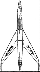
 Yes this is a fictional spacecraft, but it was designed by G. Harry Stine, former project engineer on the Viking and Aerobee rocket programs at White Sands Proving Ground. Mr. Stine used the Absyrtis in his novel CONTRABAND ROCKET written under the nom de plume "Lee Correy".
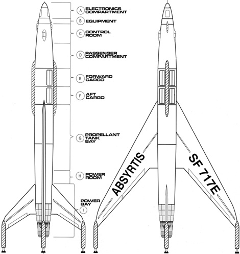


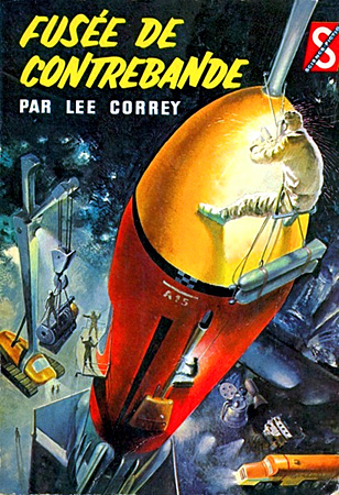

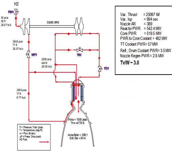
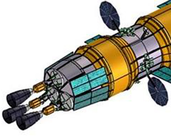
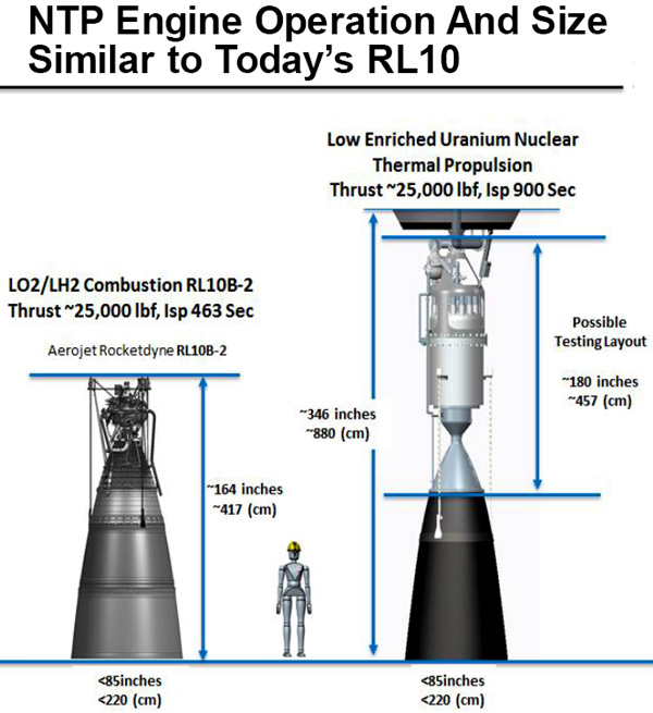
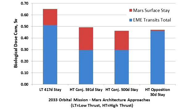
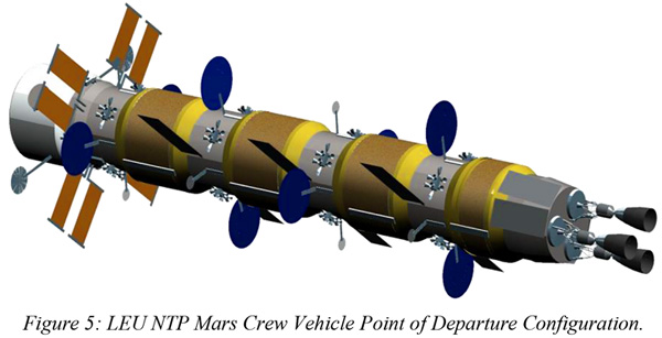


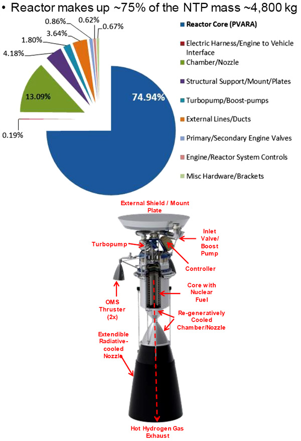


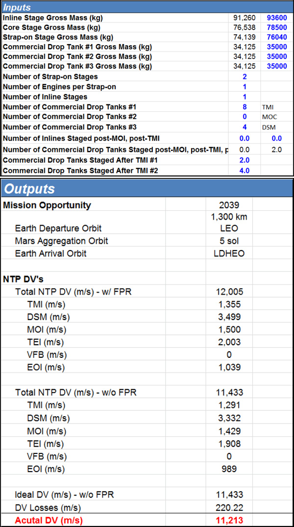
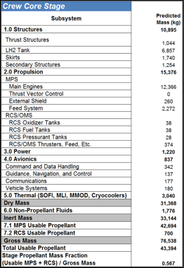
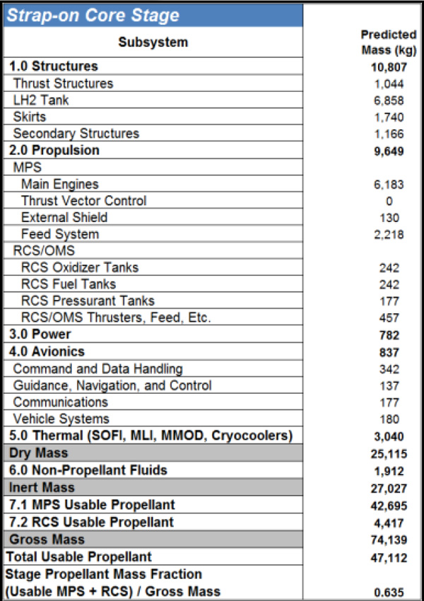
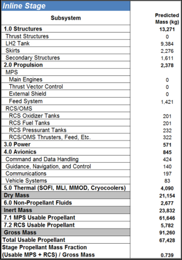
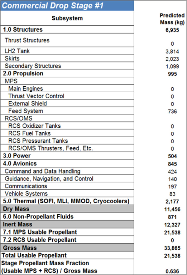


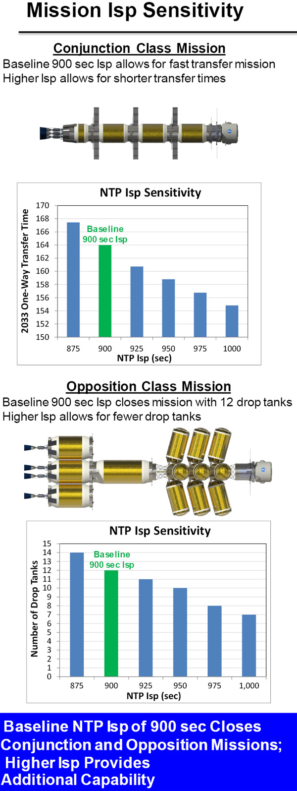
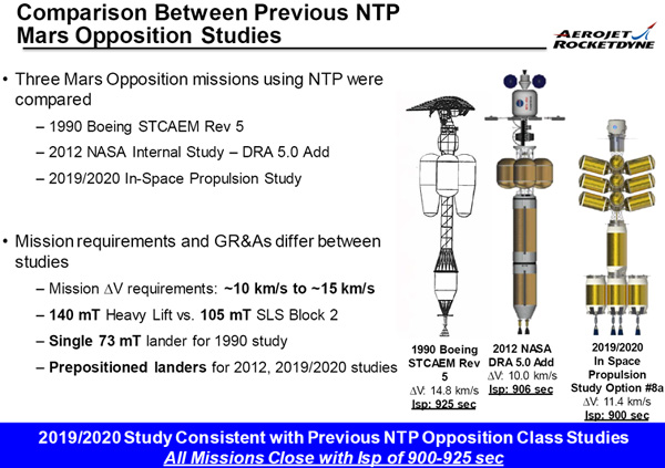


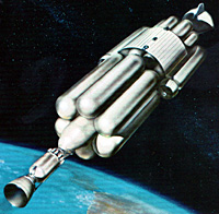
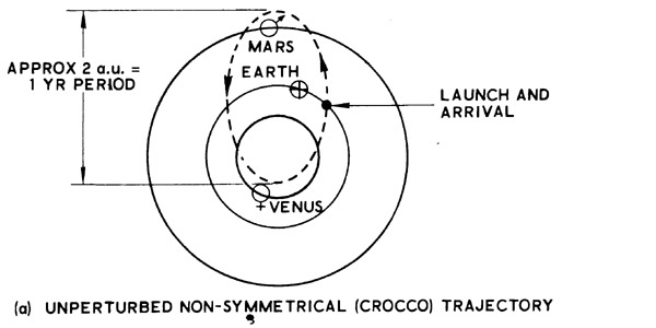
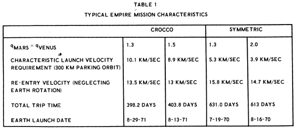

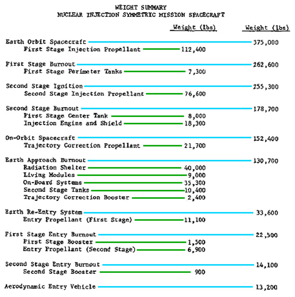


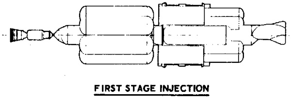
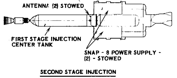
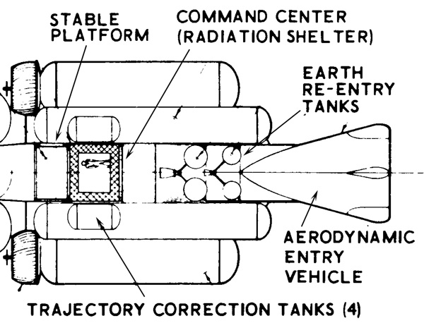
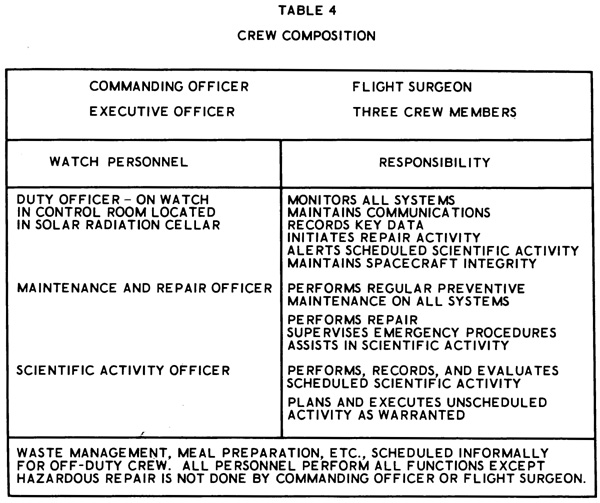
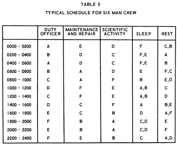
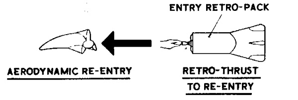
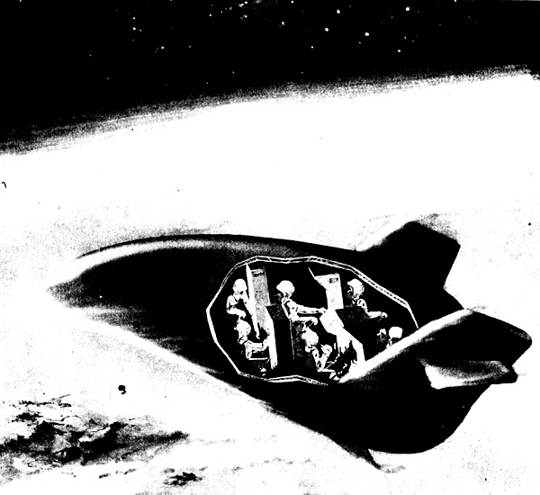
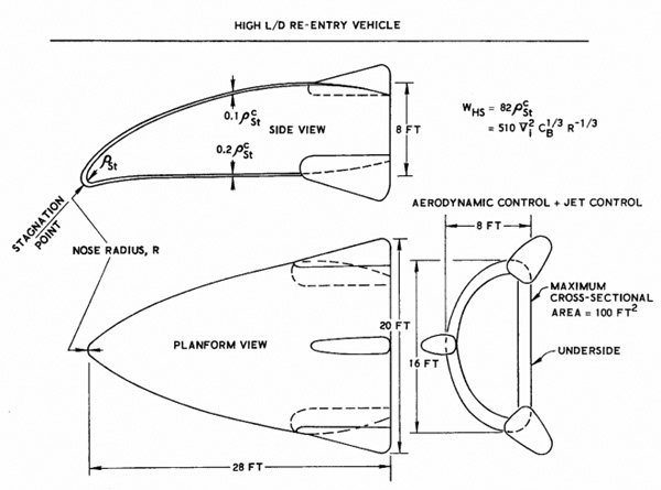


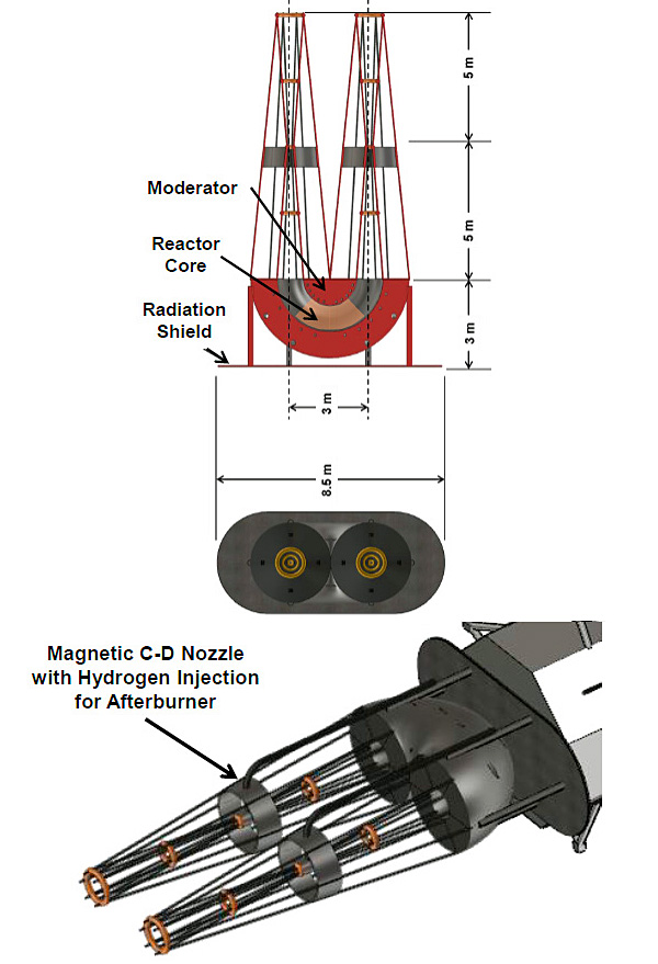

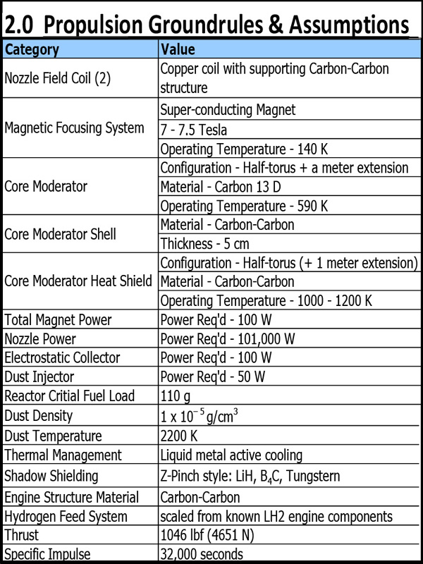

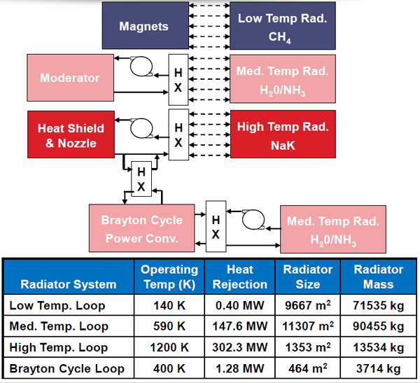
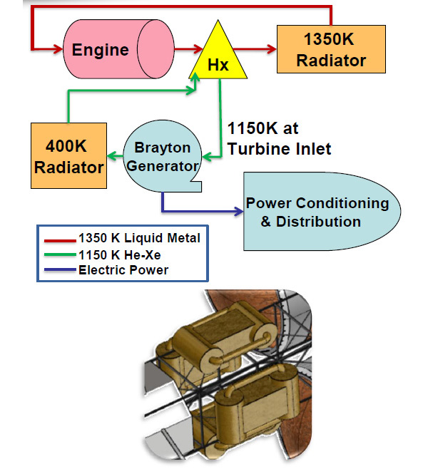
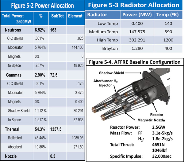
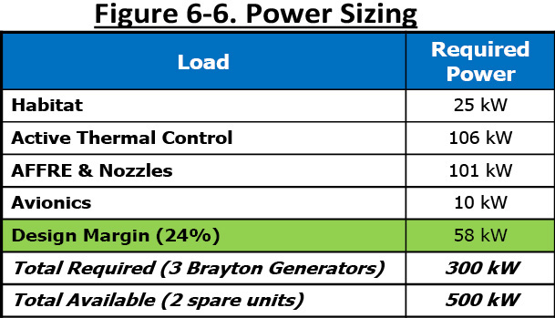
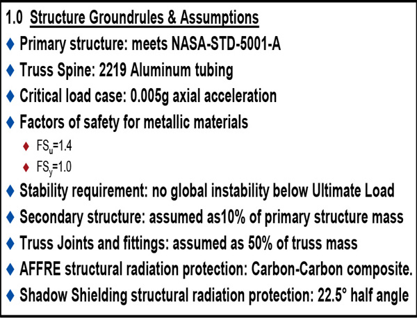
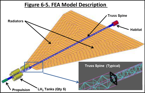


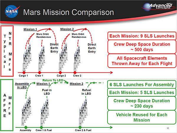
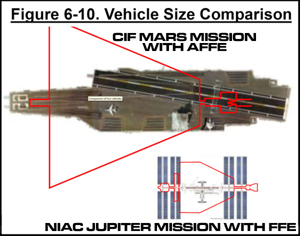
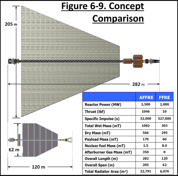
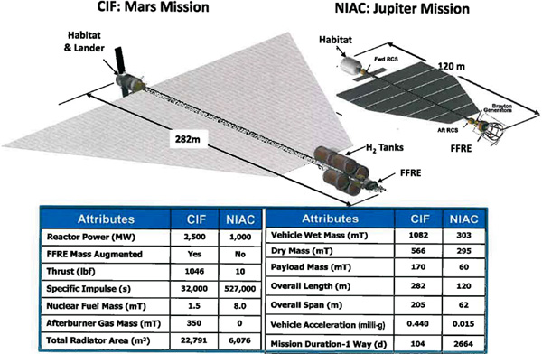
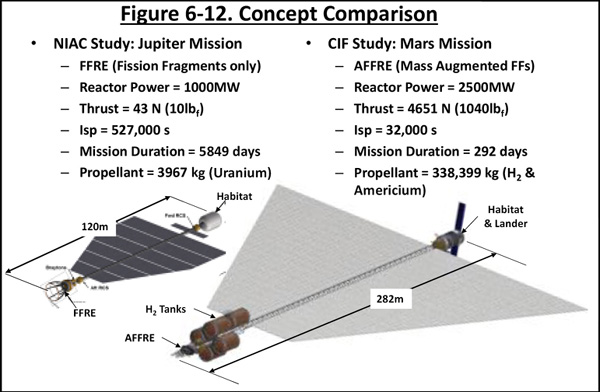


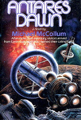

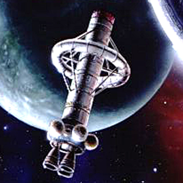
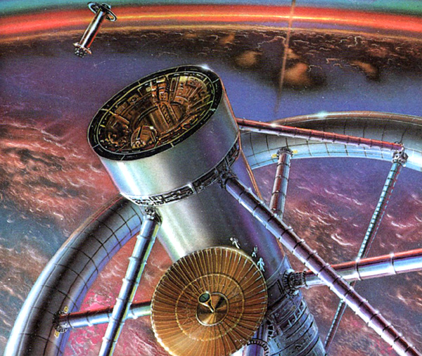

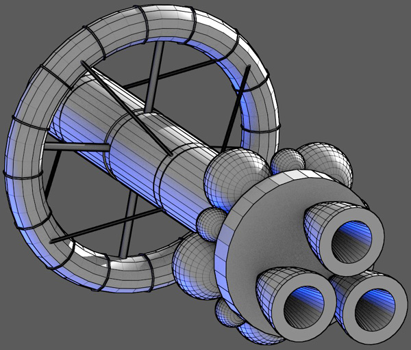
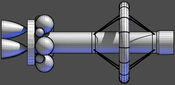
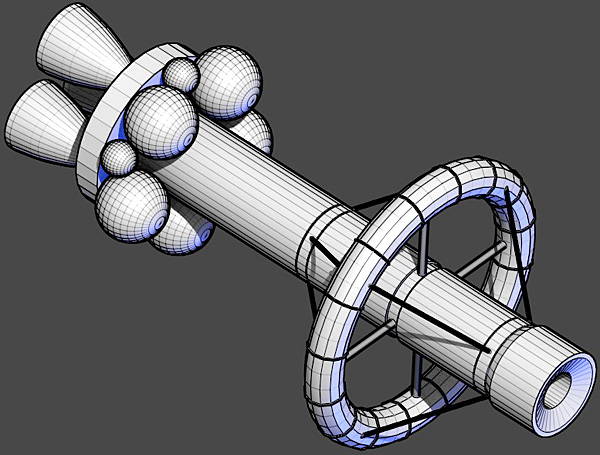

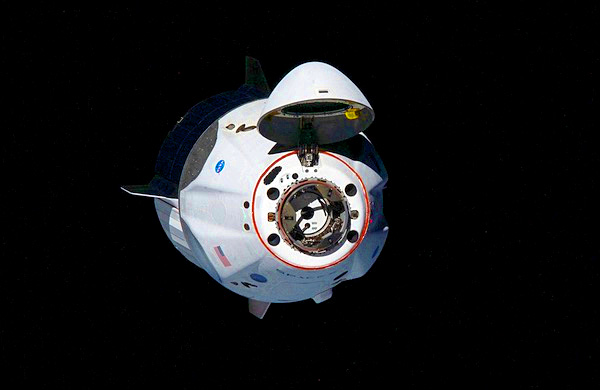
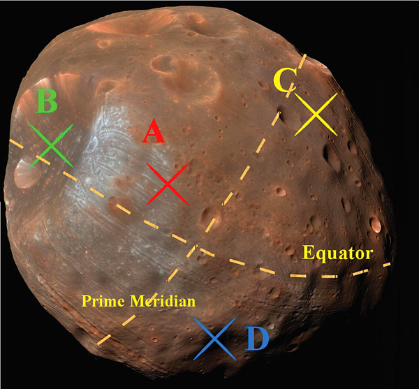
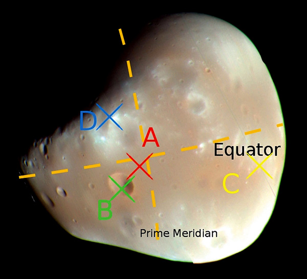

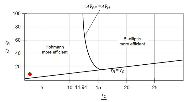
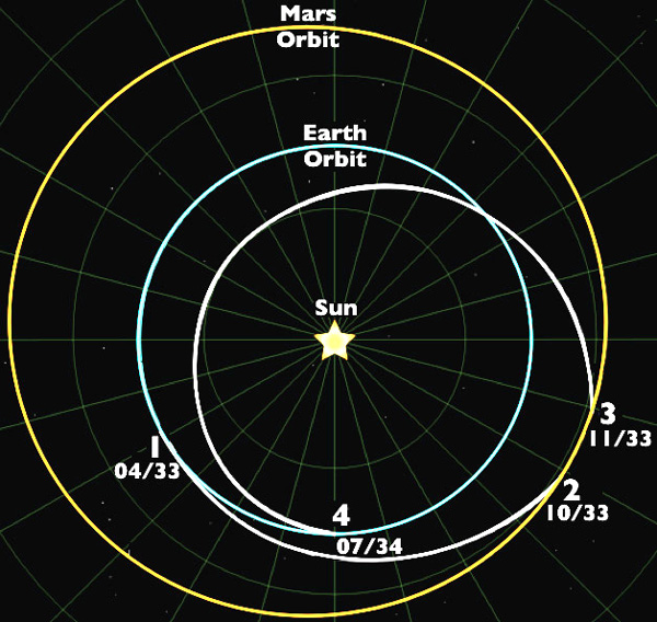
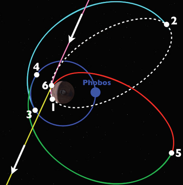
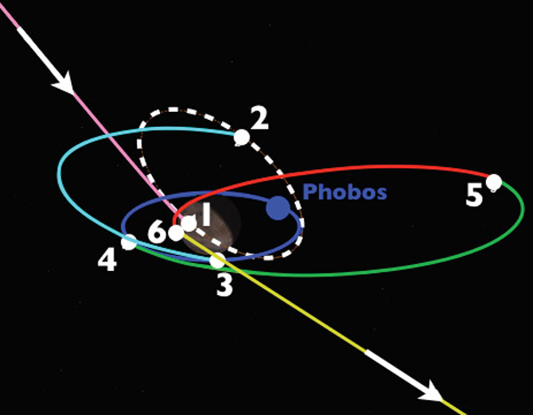
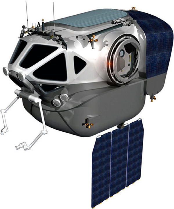
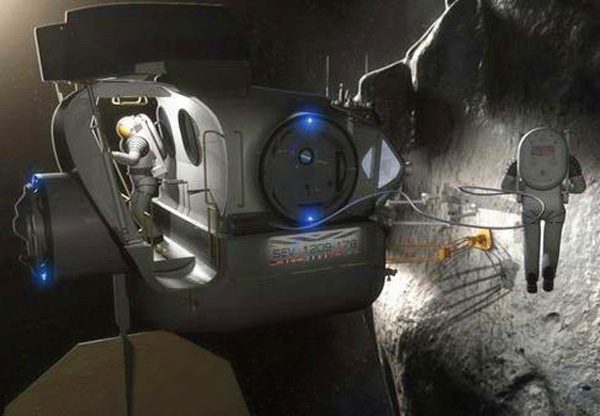
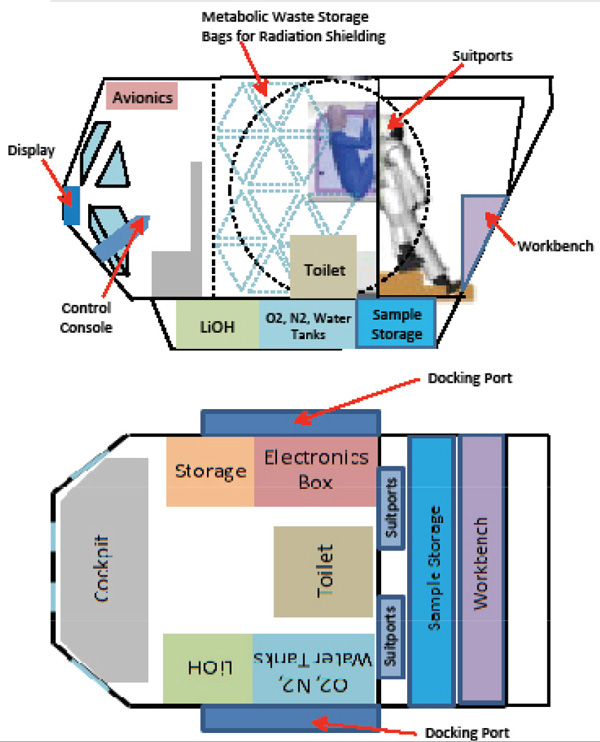
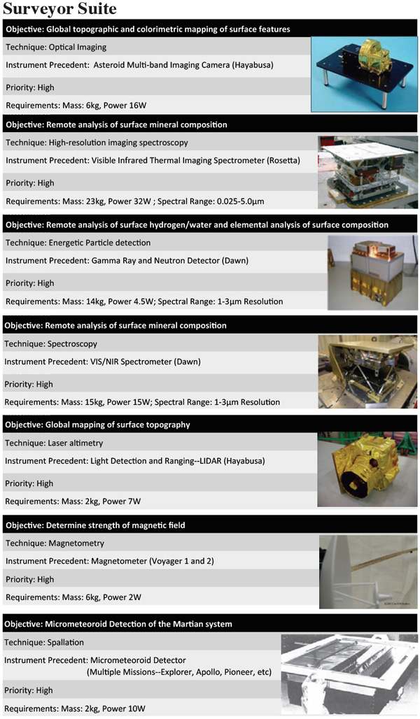


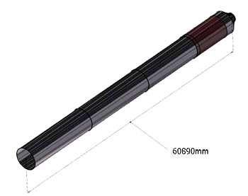

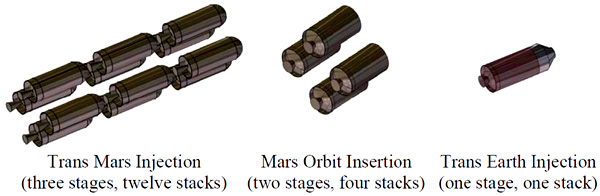


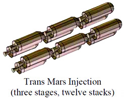
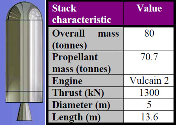
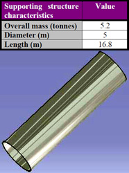
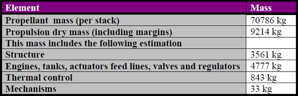
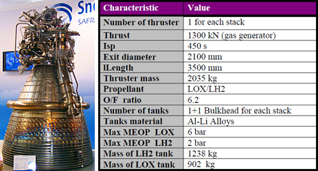
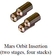
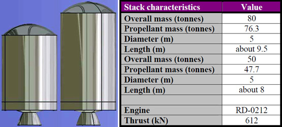
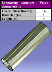
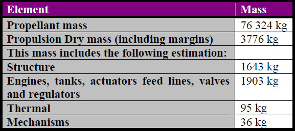
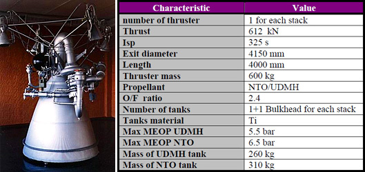
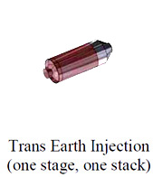
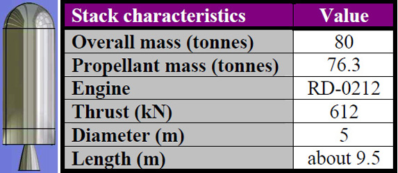
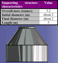
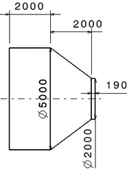
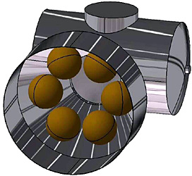
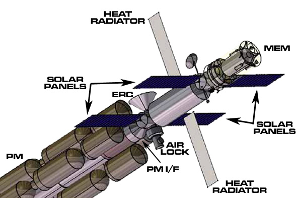
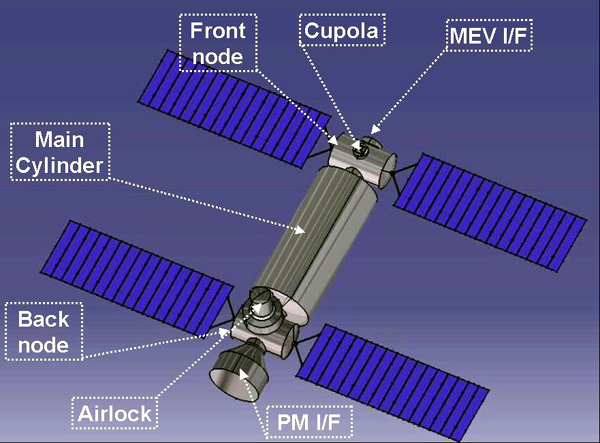
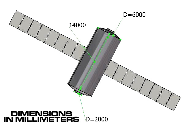
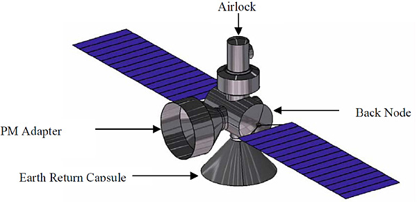
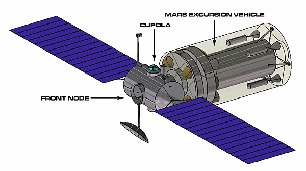


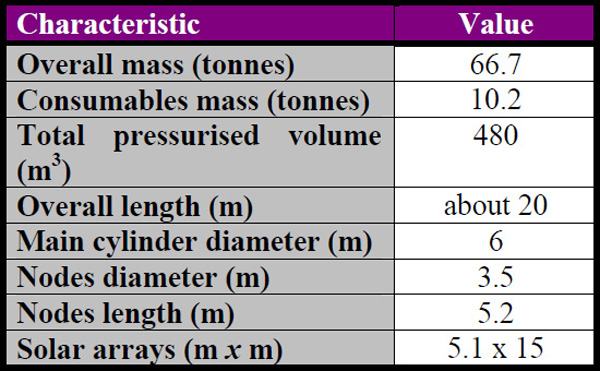

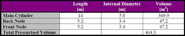


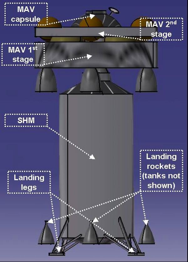
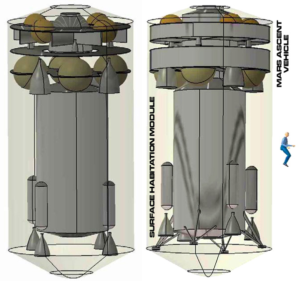
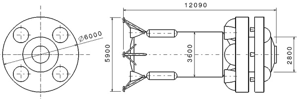
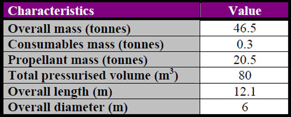
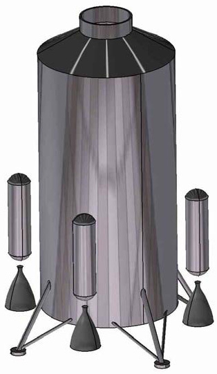
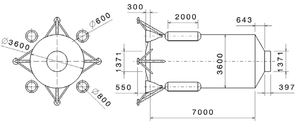
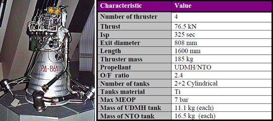


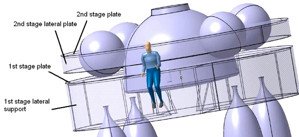
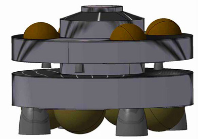
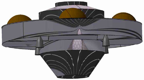
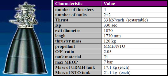


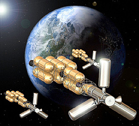
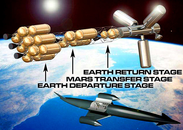
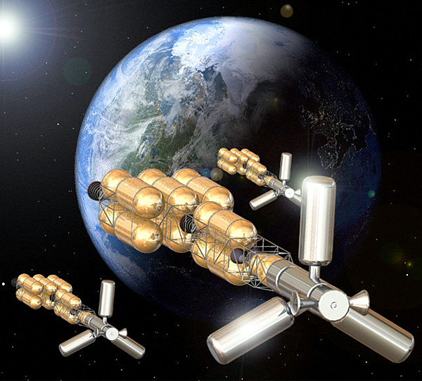
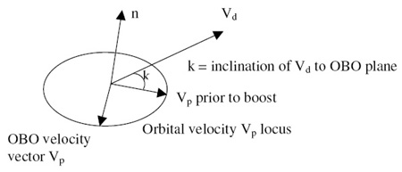

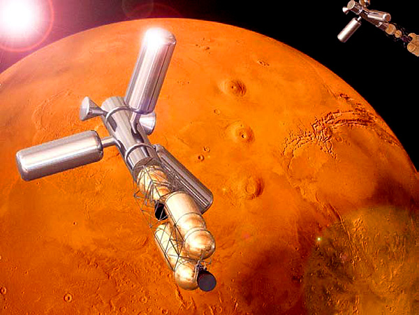
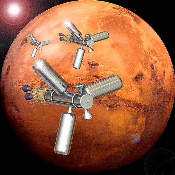


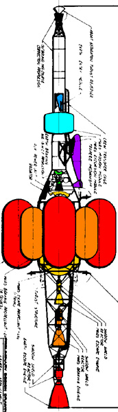


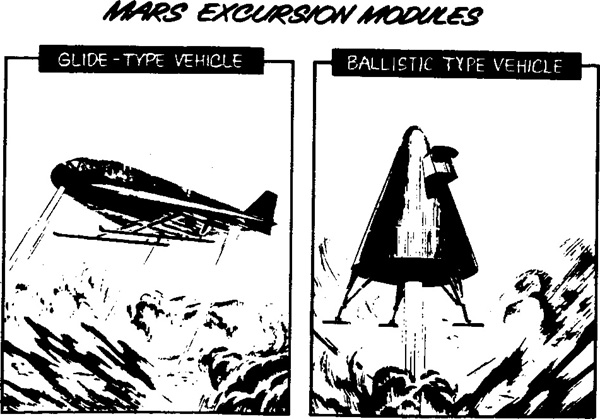
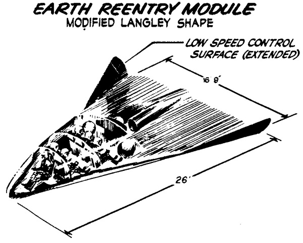


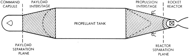
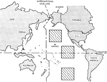
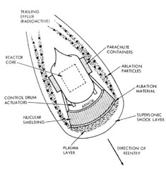
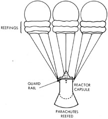
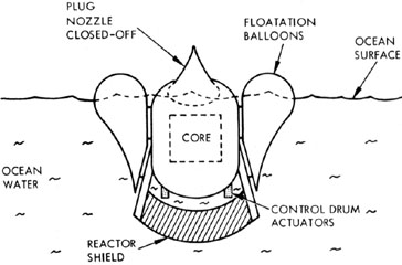
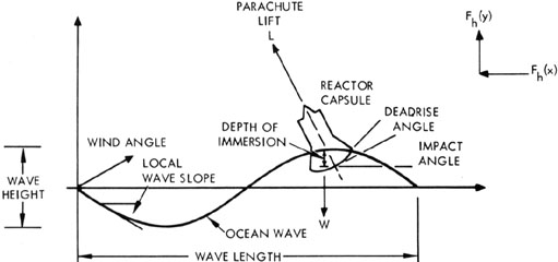
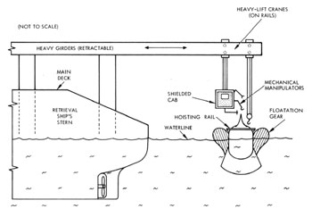
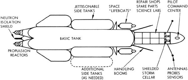
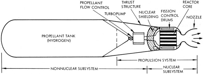
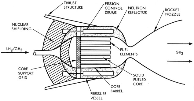
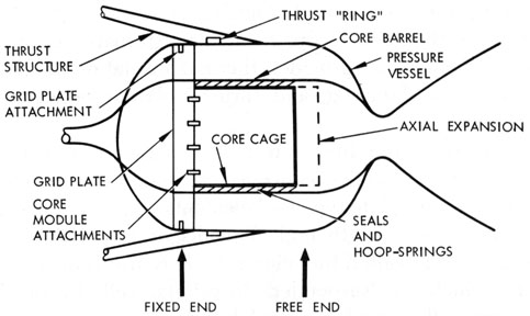

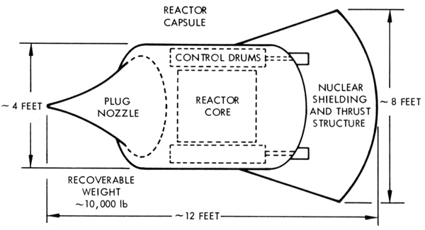
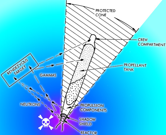
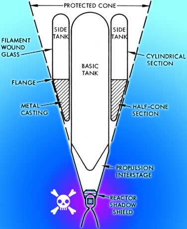
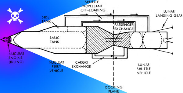
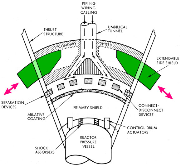
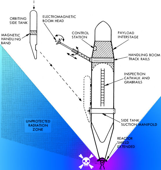
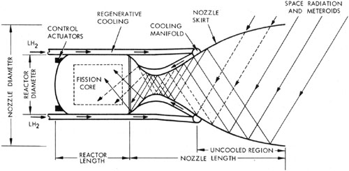
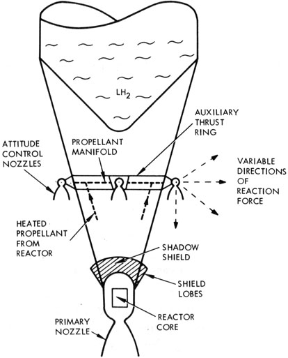
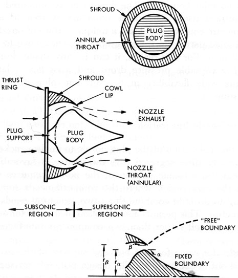
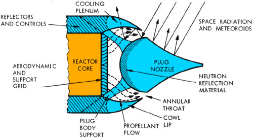
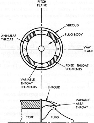
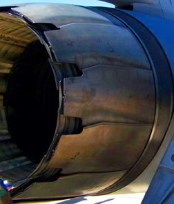
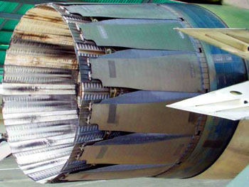
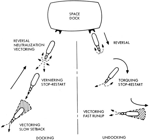
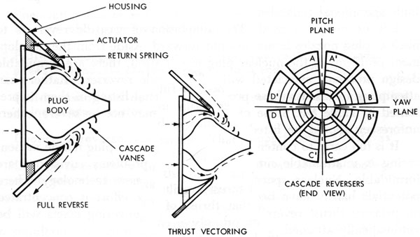
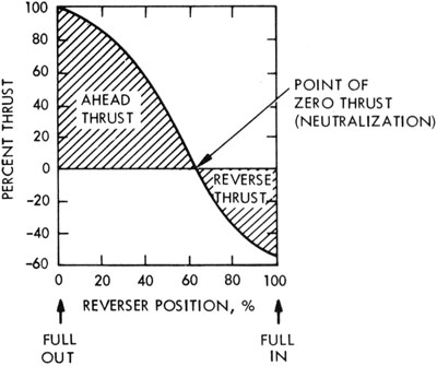

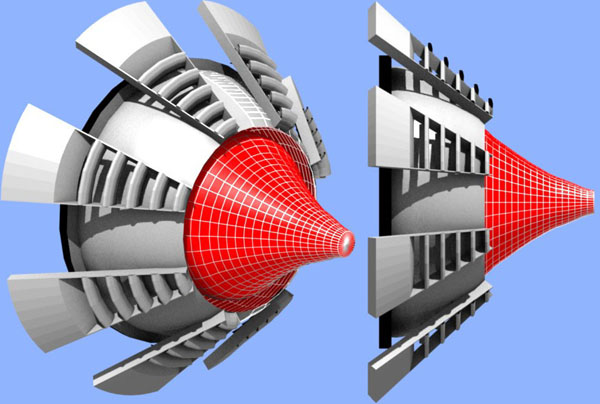
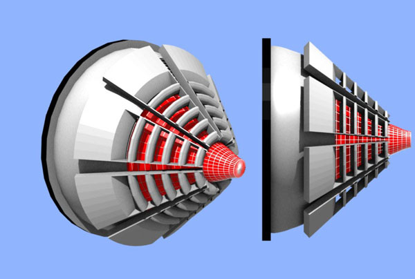
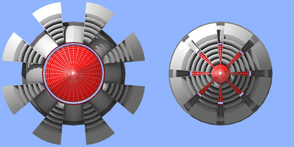
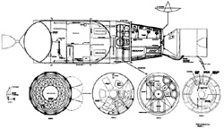

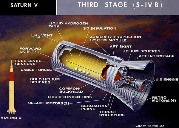


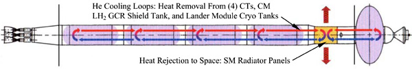


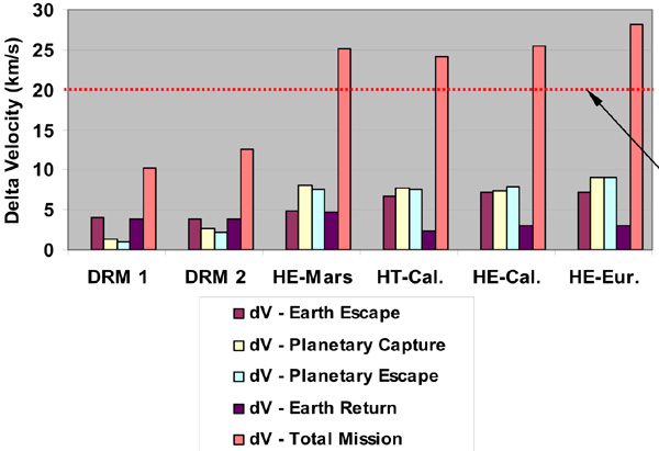
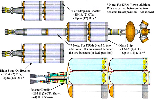
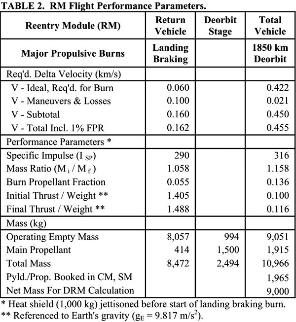
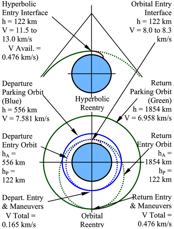


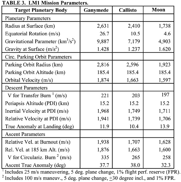
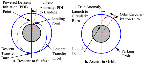
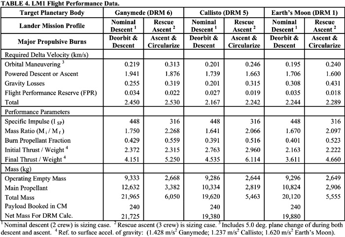


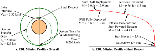
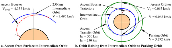
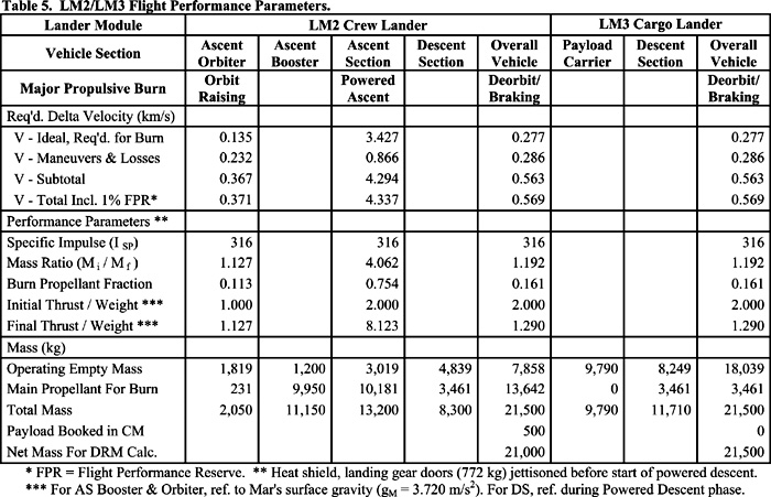


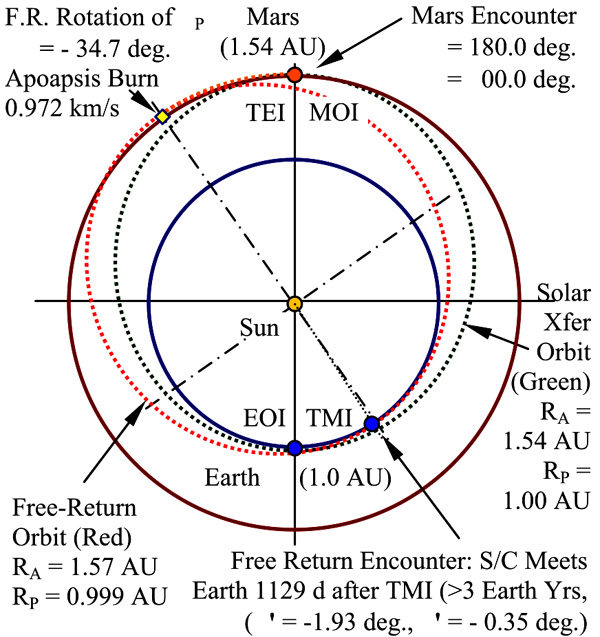
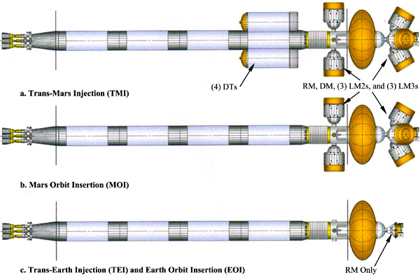


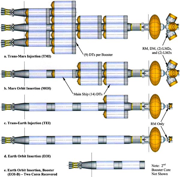
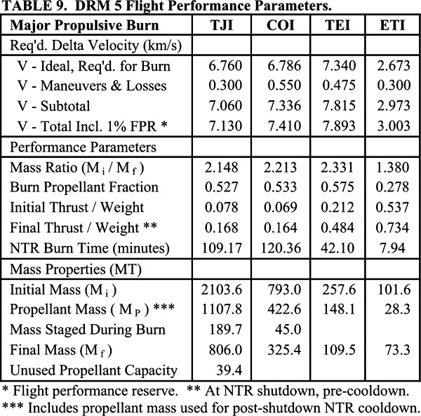
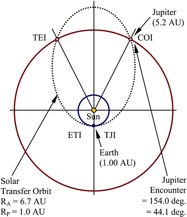
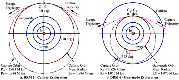
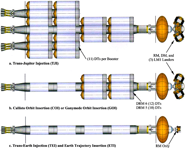

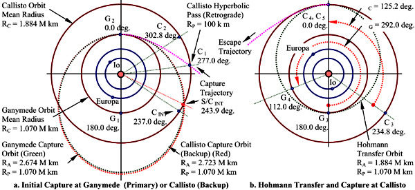
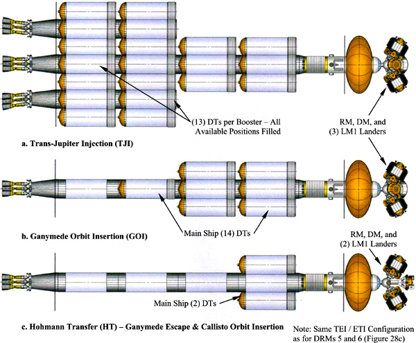
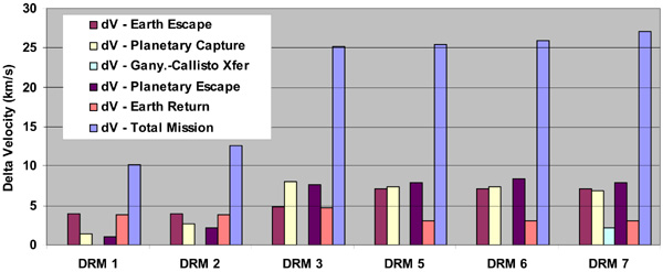
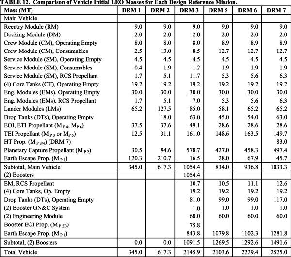
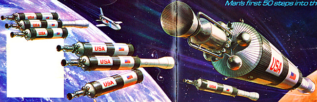
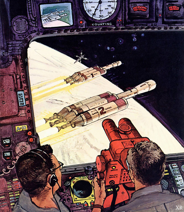

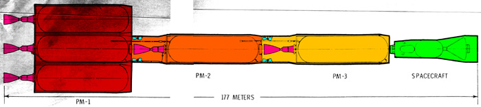

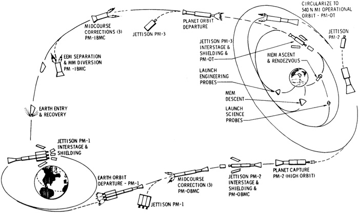
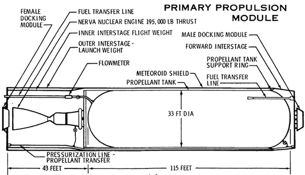


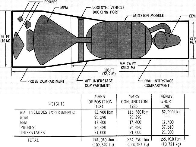

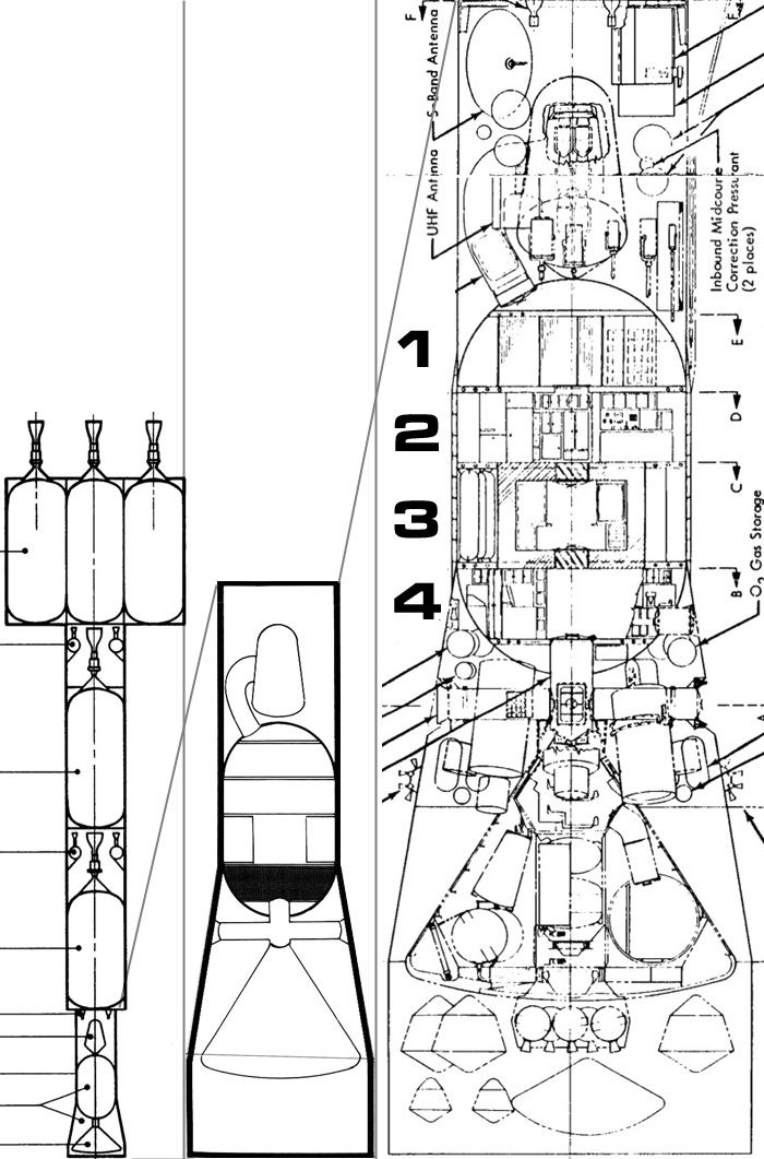


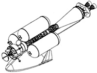


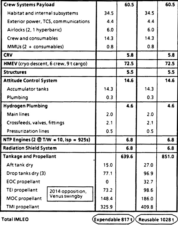


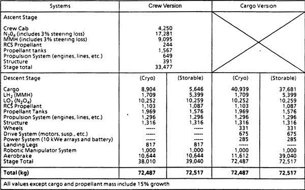


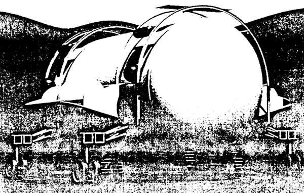
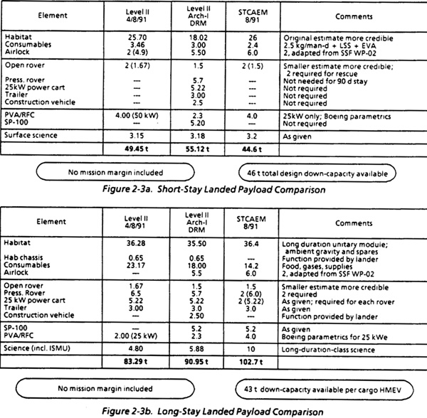


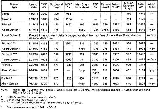
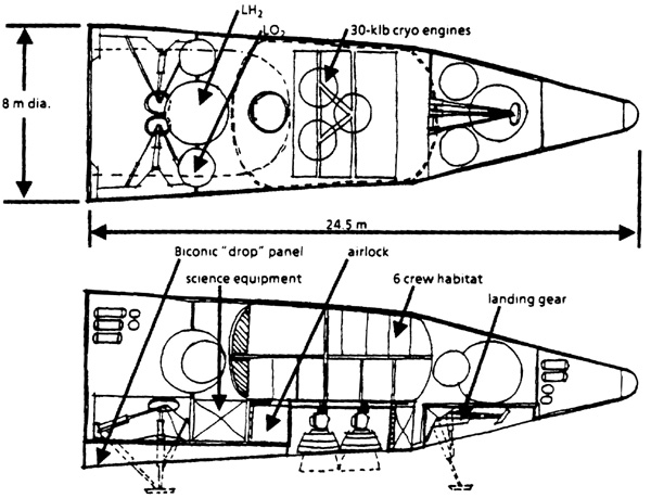
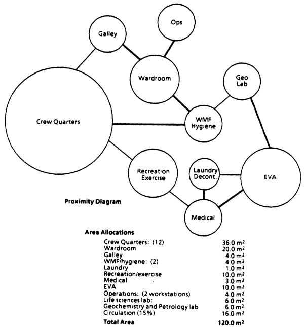
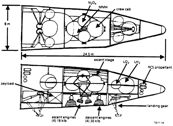


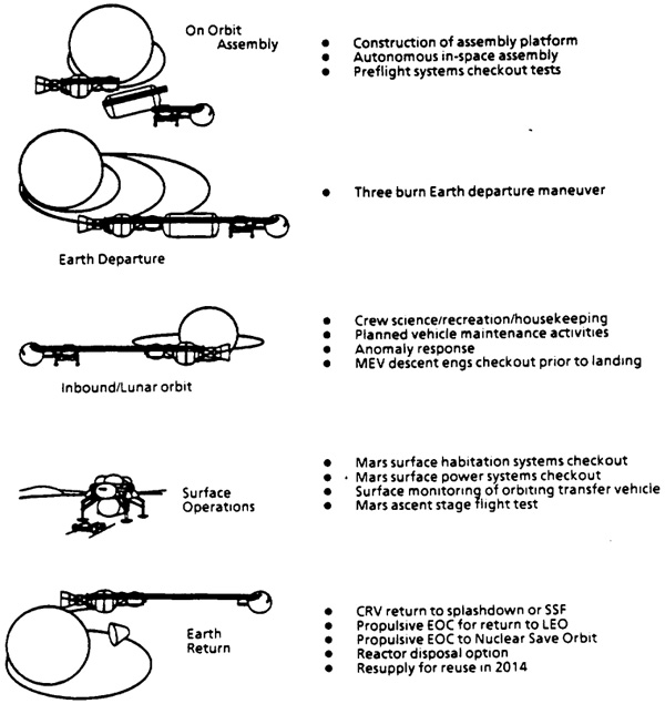
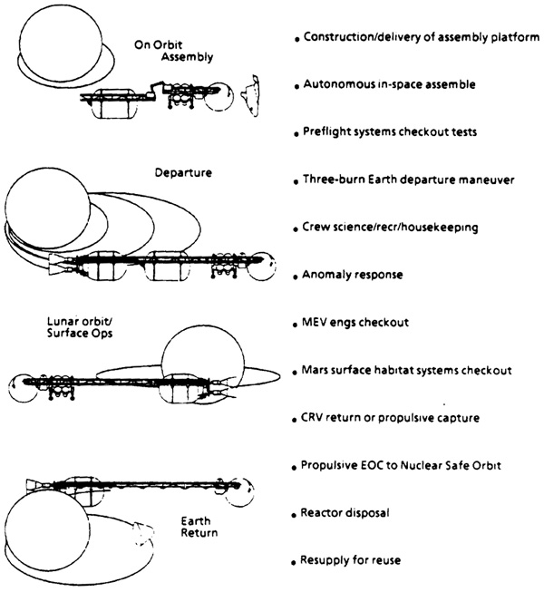


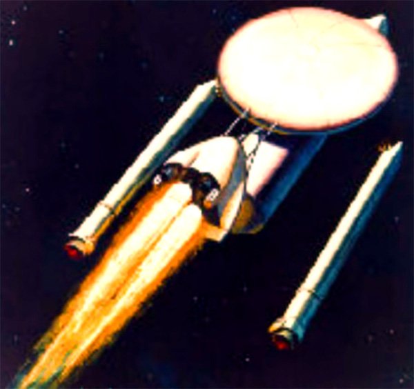


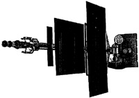


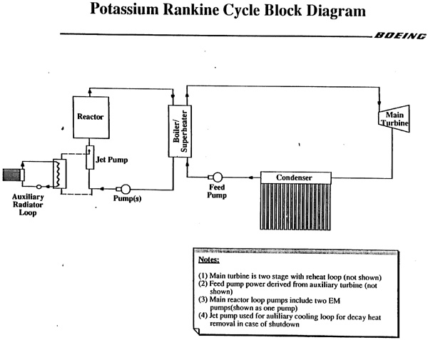


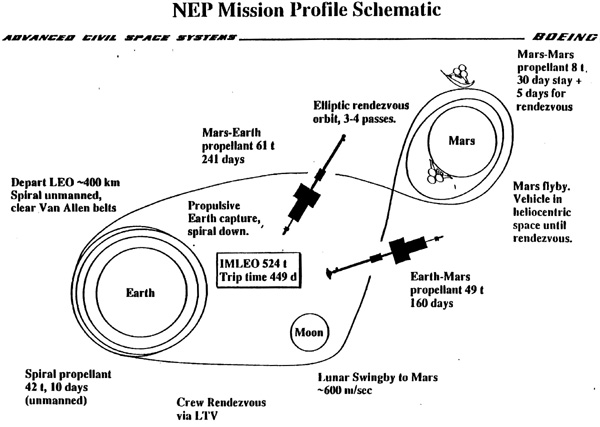
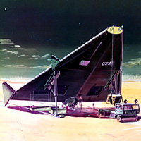


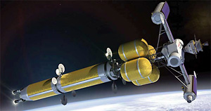

 Spacecraft (black) is safely inside the white cone shadow cast by the anti-radiation shadow shield. The purple-blue area is the zone of deadly radiation created by the nuclear engines.
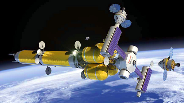
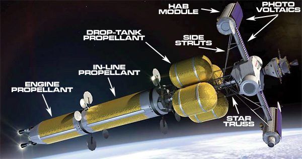

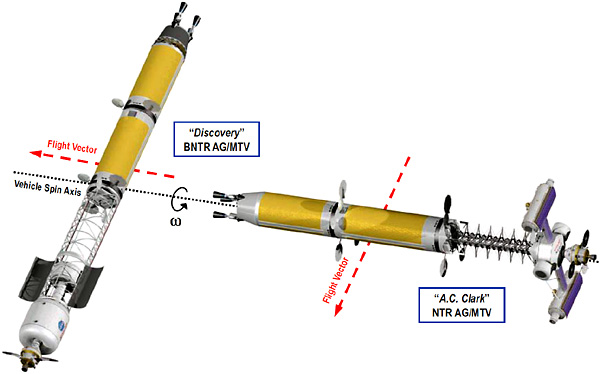


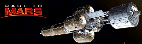
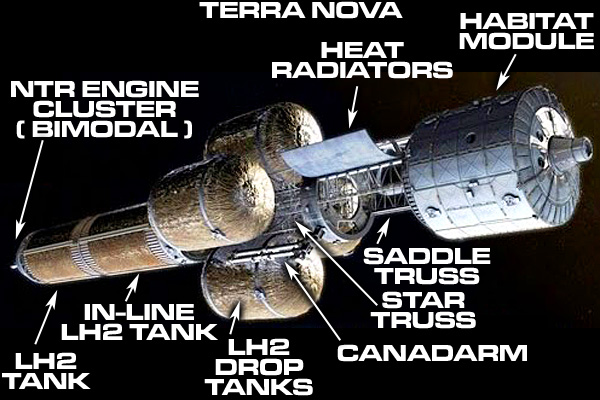
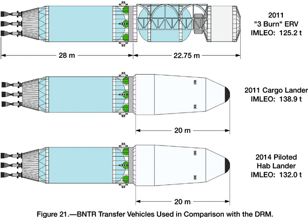
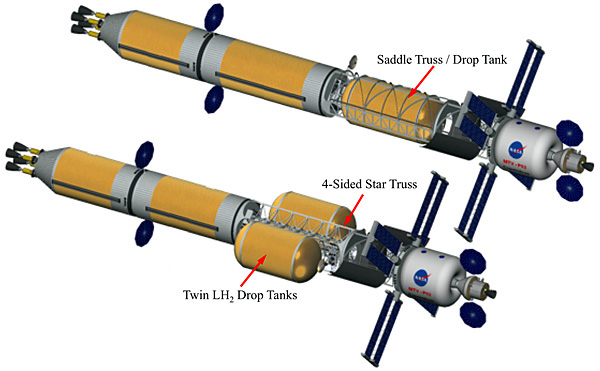
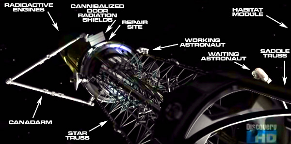
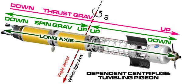
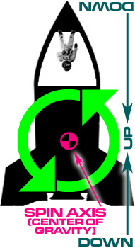

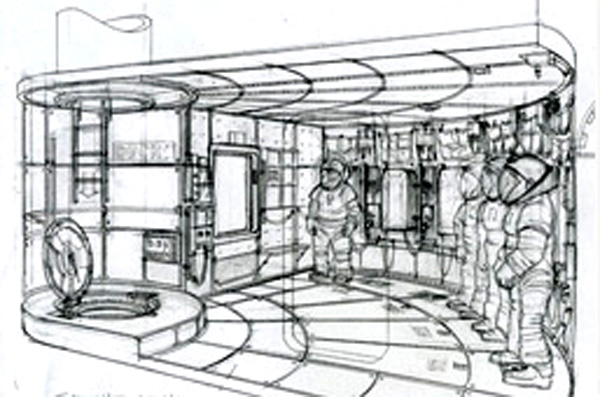
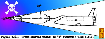
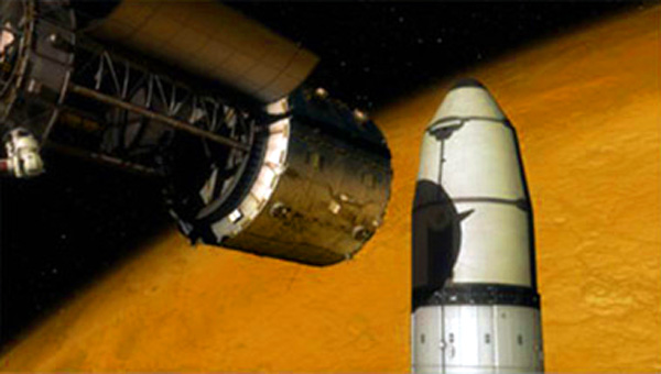
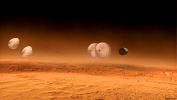
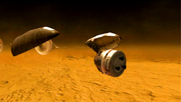
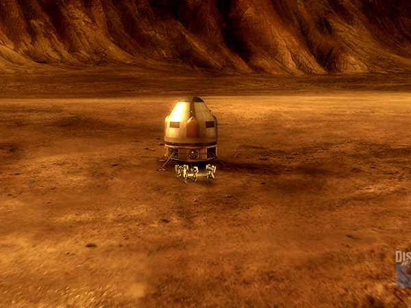
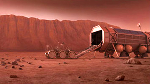
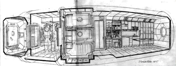
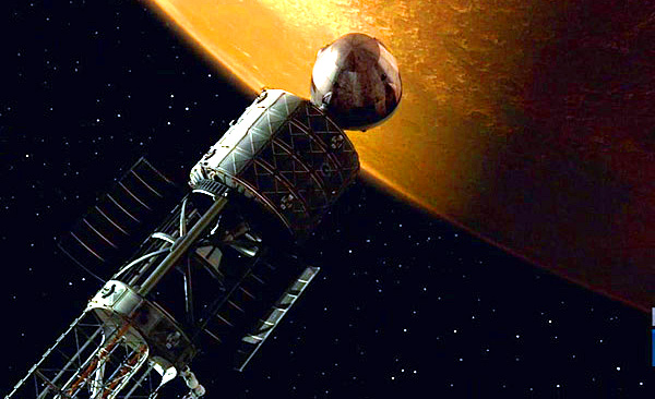
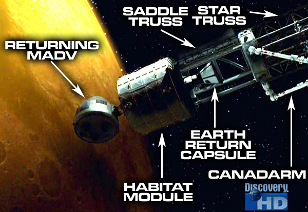


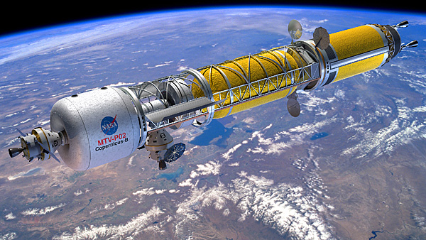
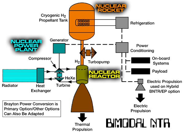
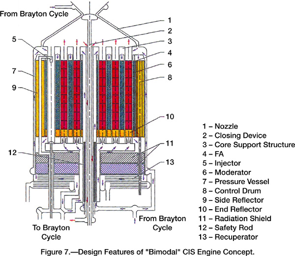
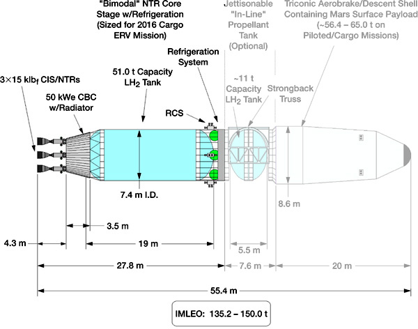
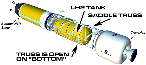
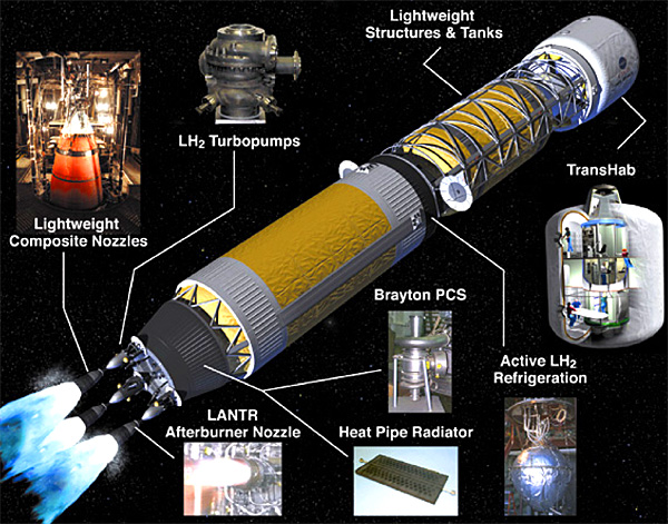
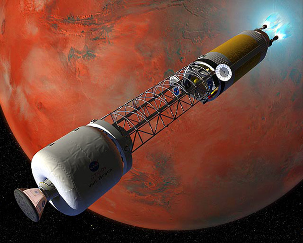
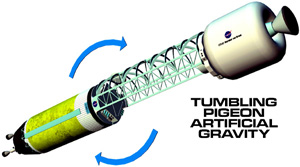
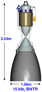
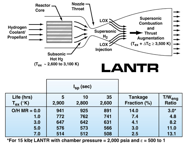
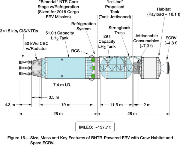
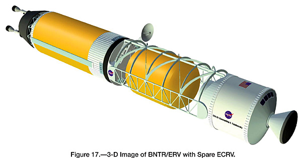

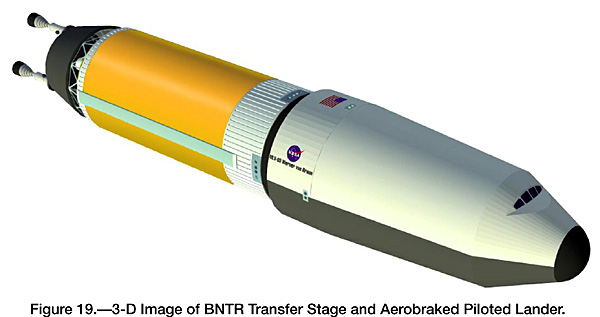
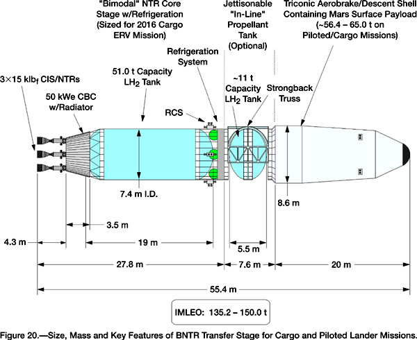

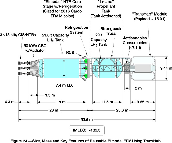
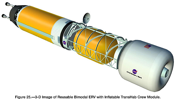
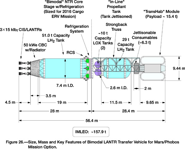

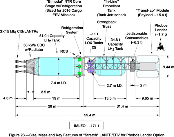
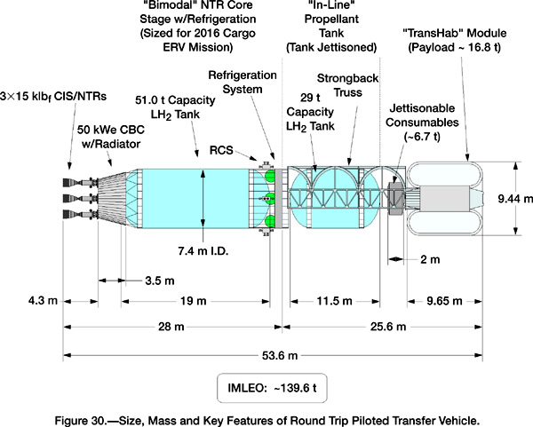
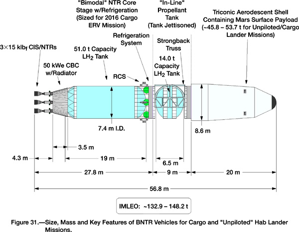
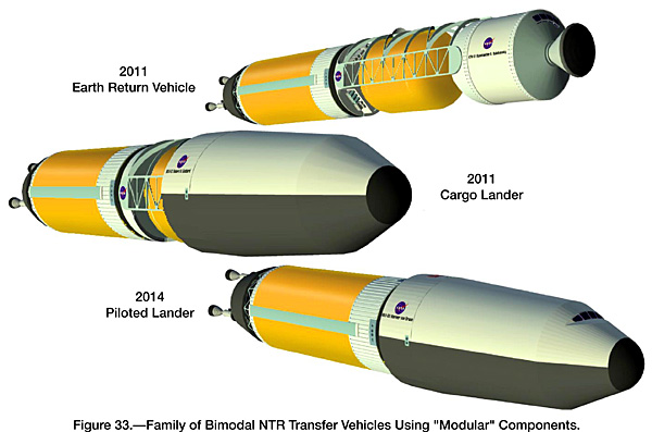
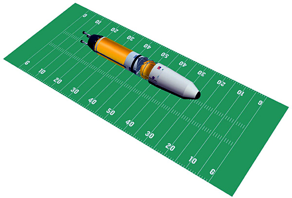
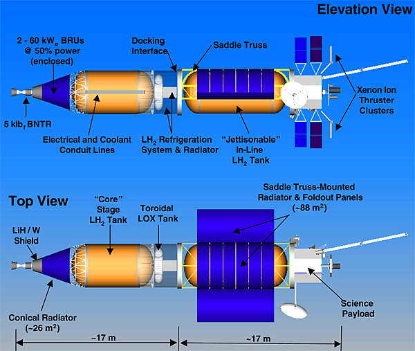


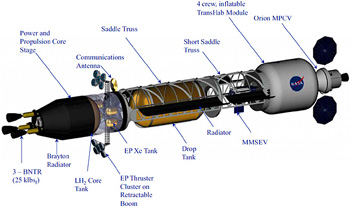
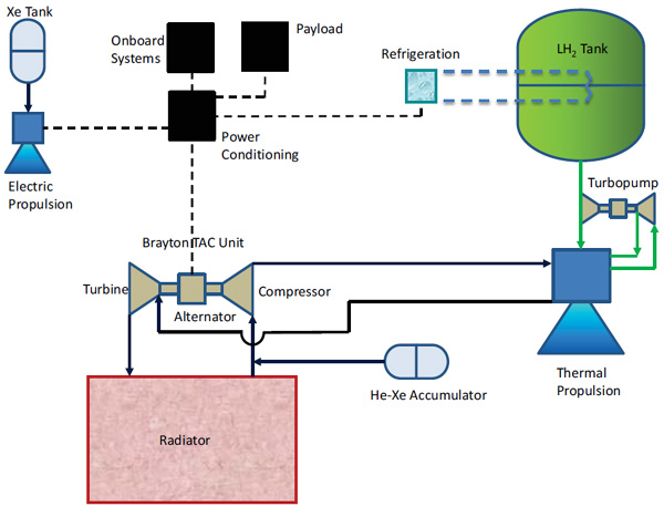
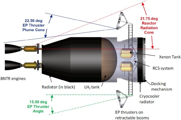
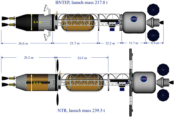
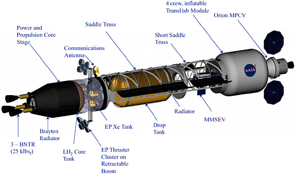
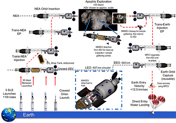

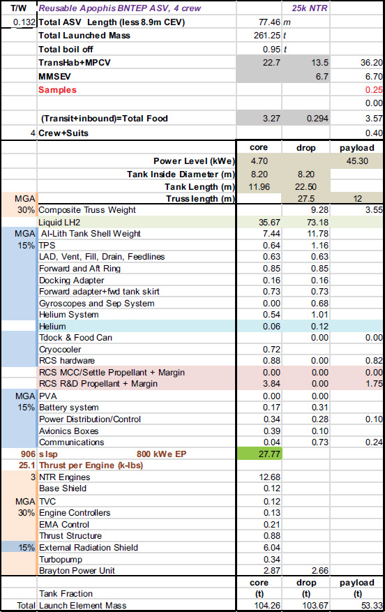

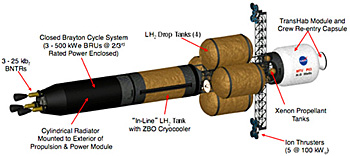


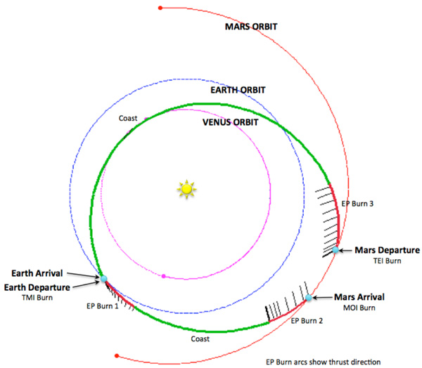
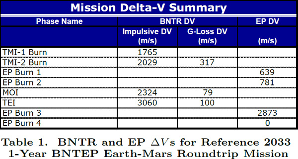


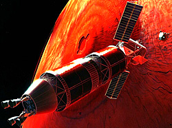


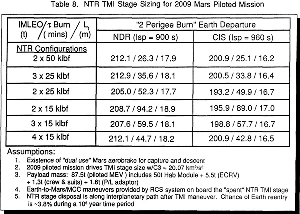


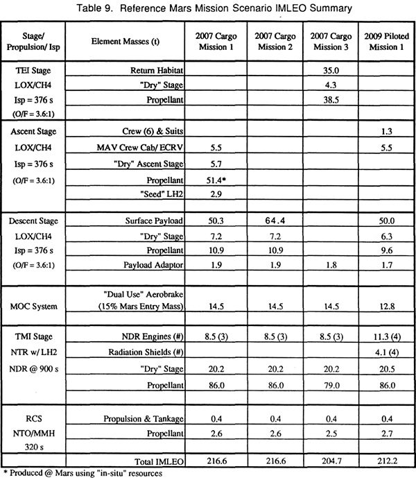
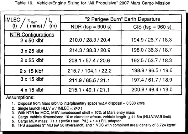

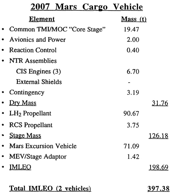

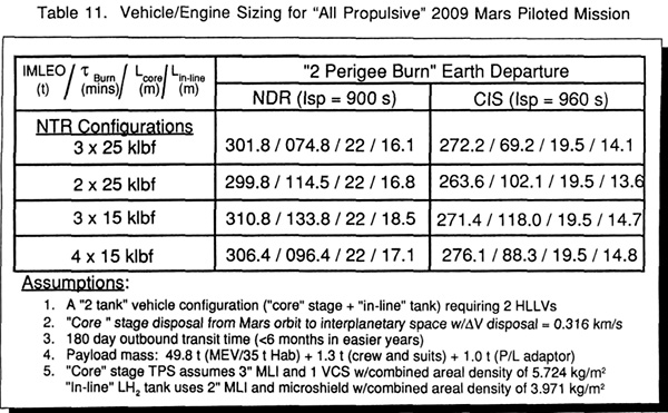

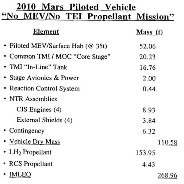

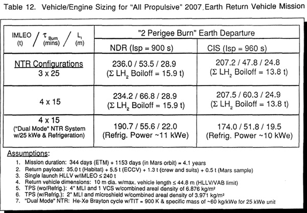

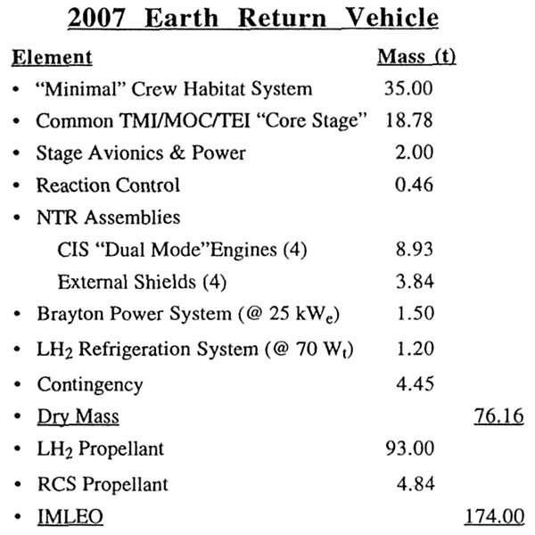


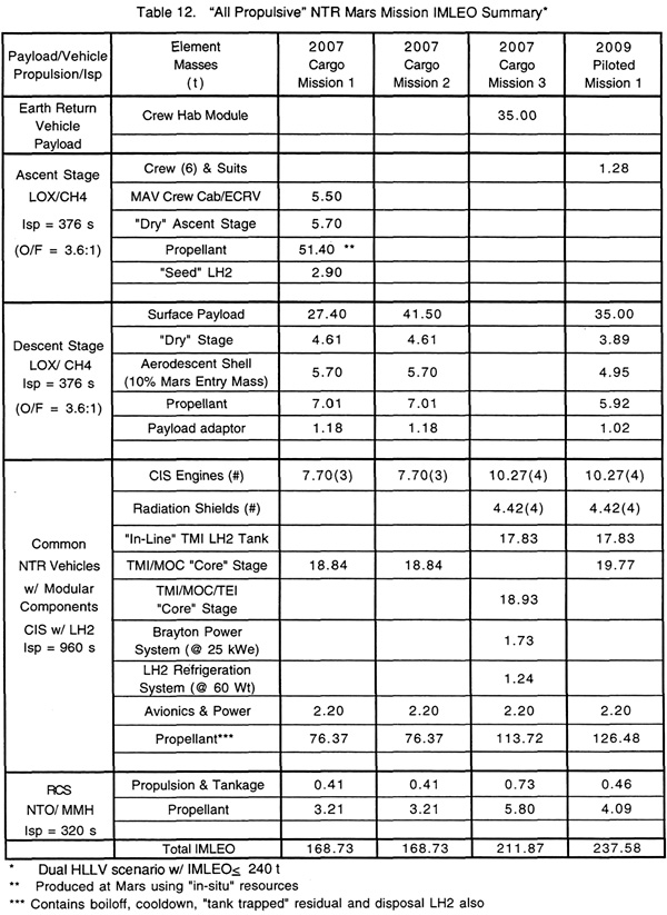


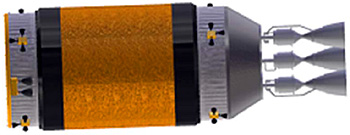


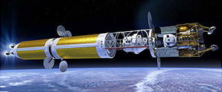
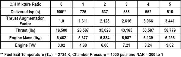
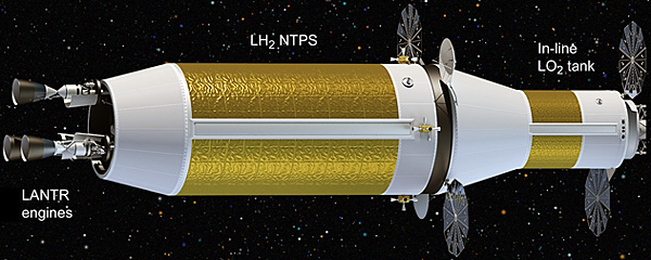


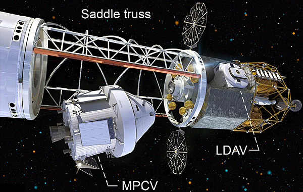
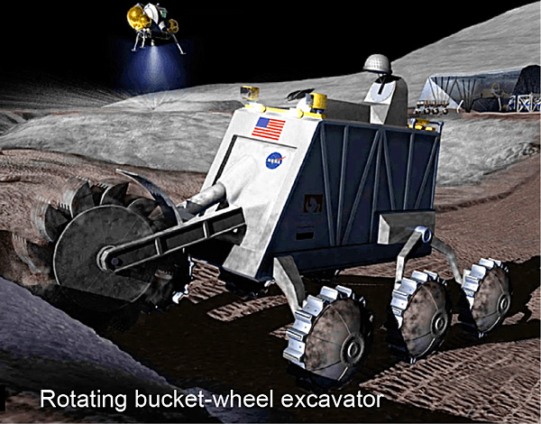


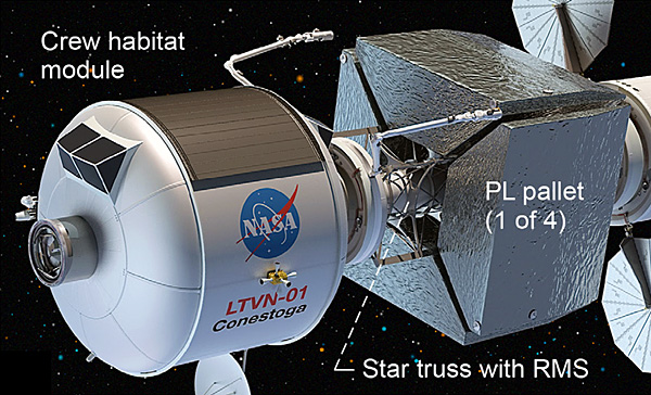


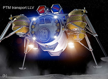
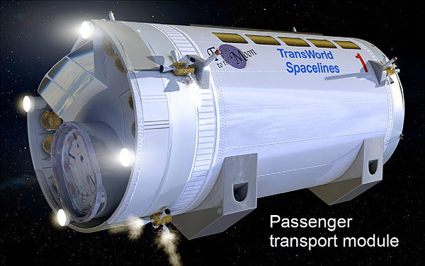


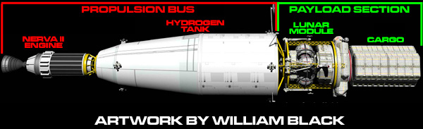


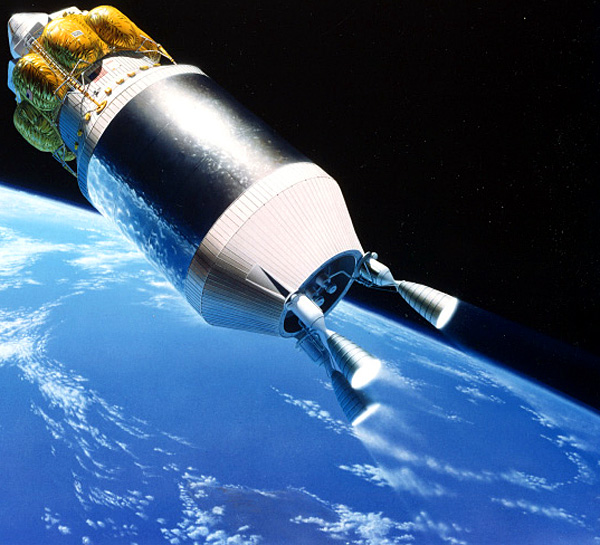
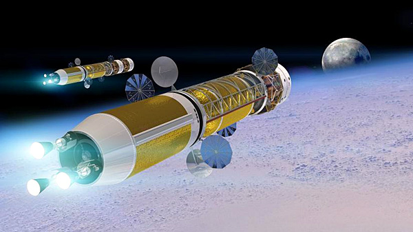
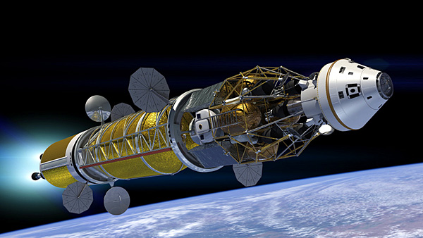


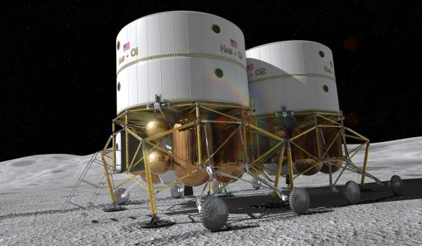

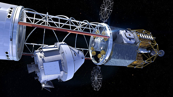


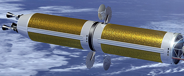


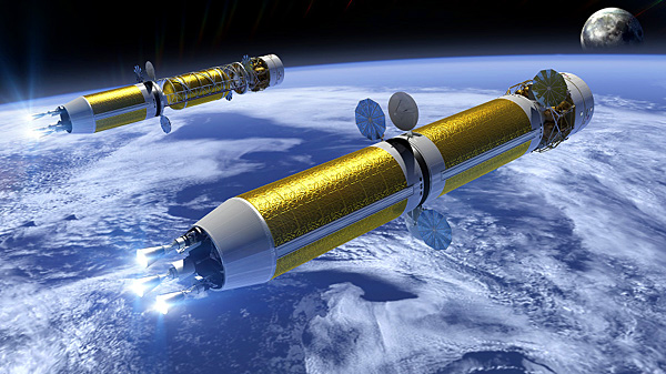
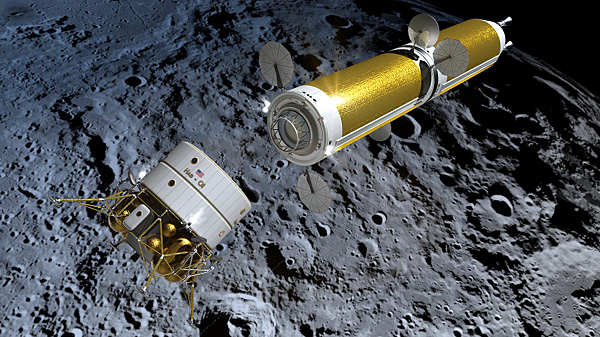
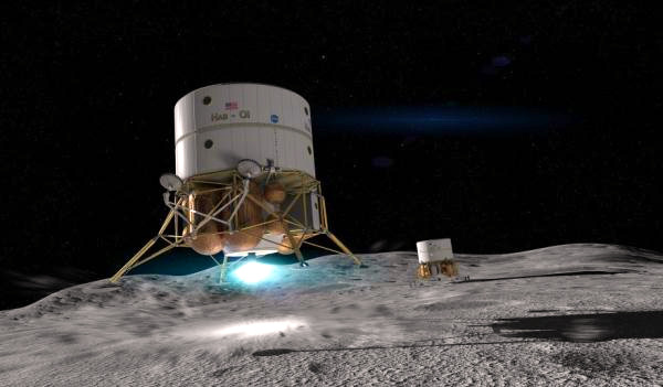


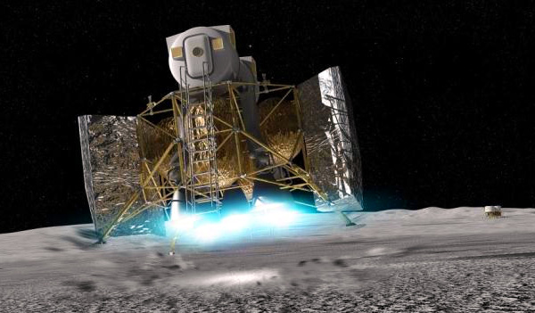


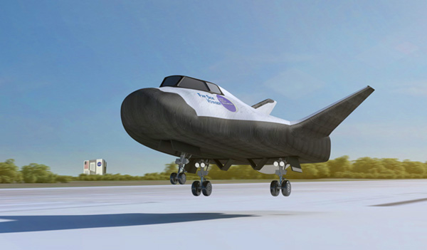


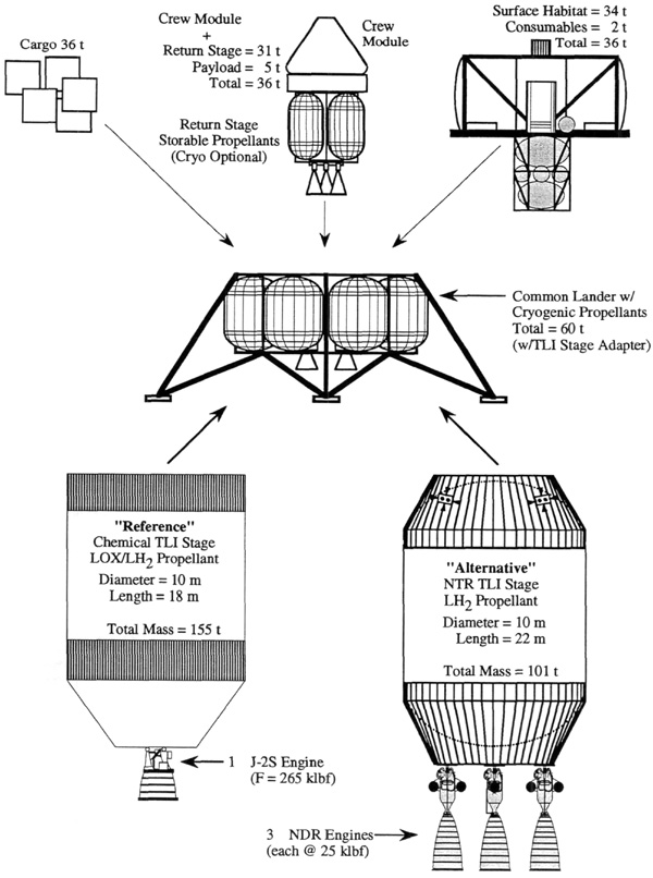

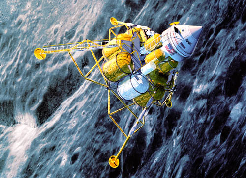
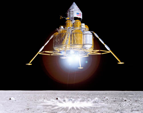
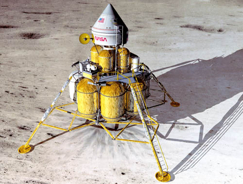
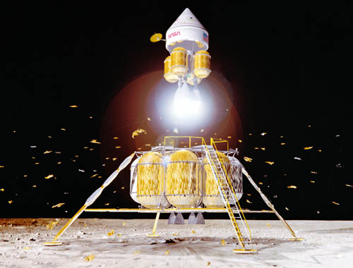
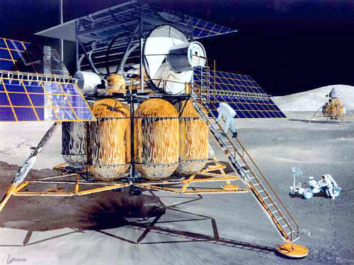


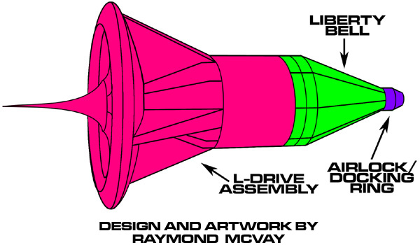
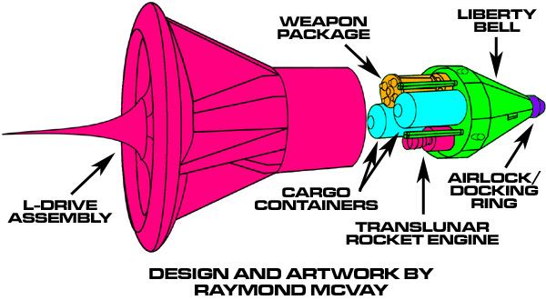
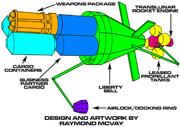
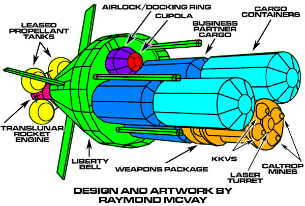
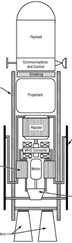


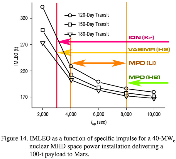

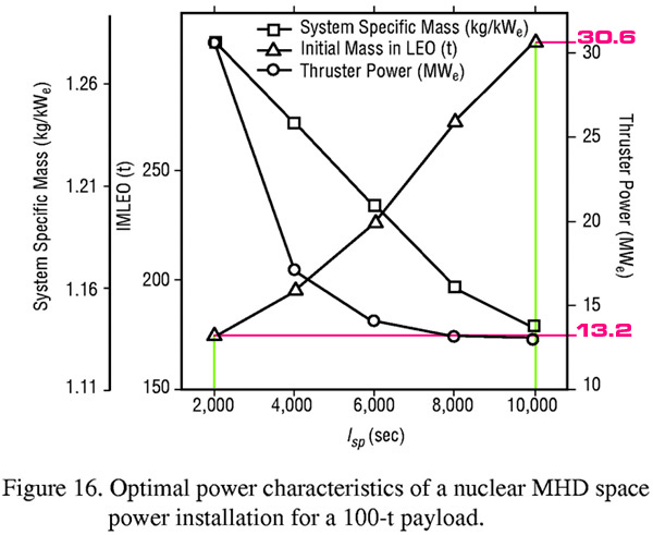

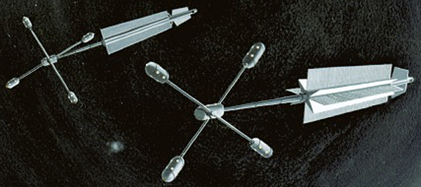
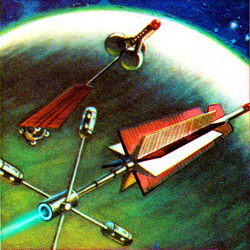


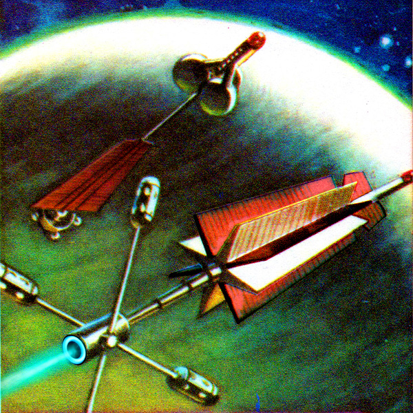


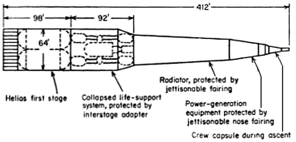
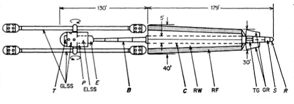
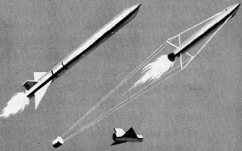

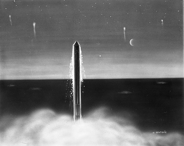
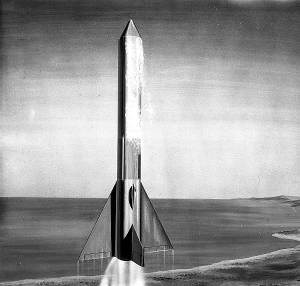
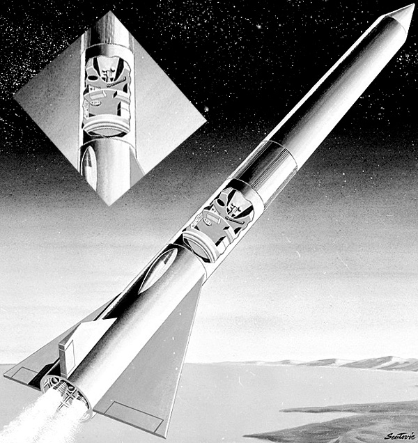
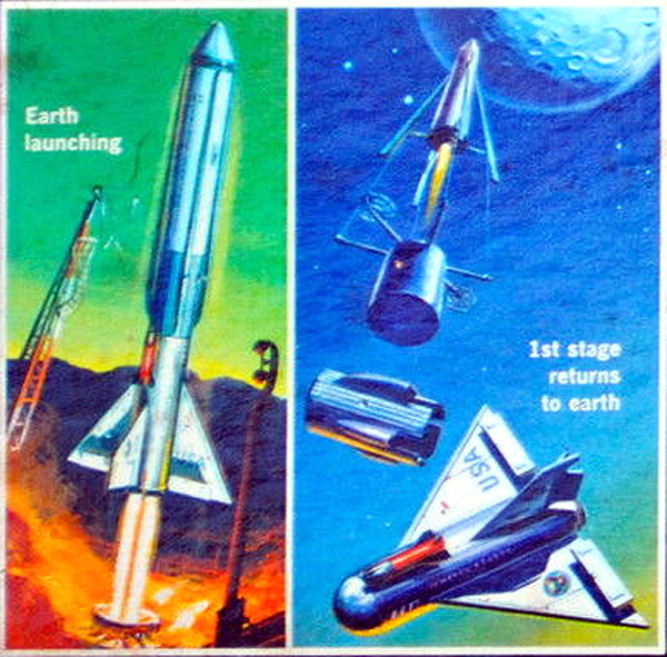
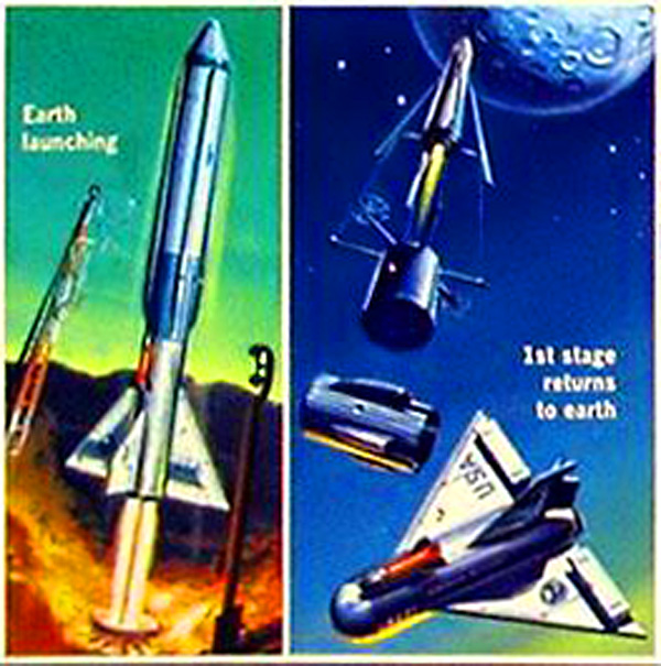
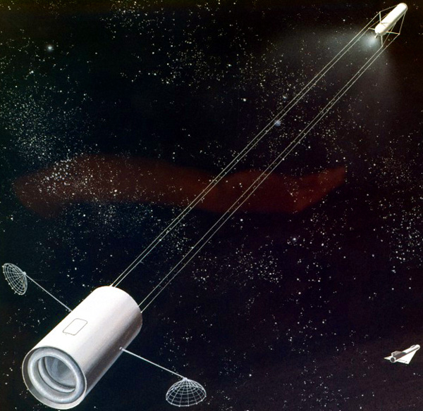
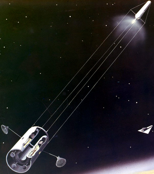
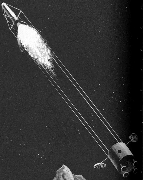

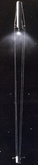
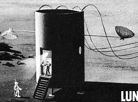
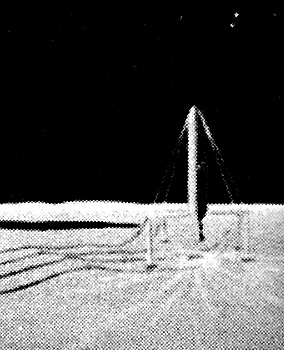

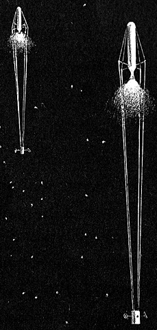
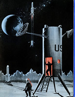
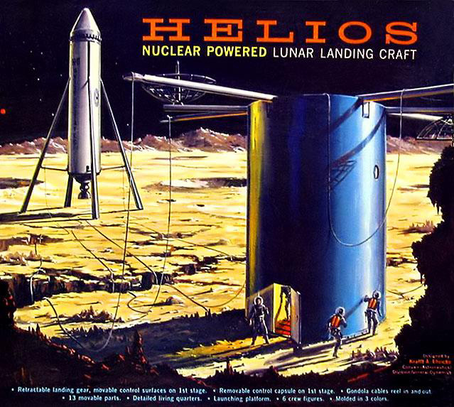
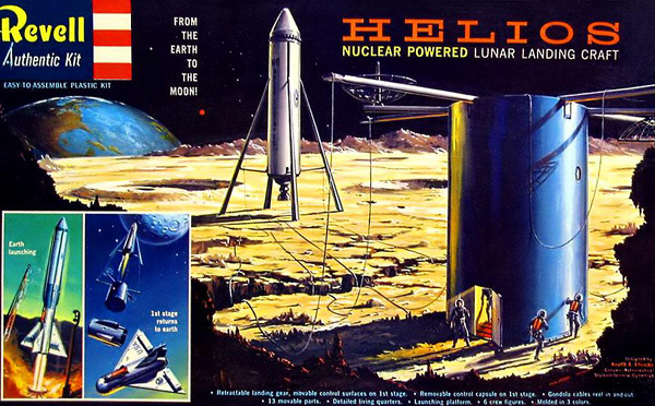
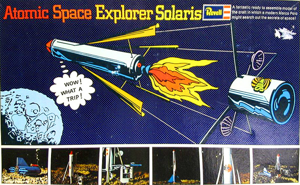
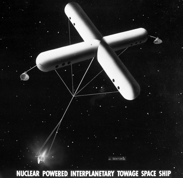
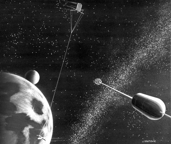
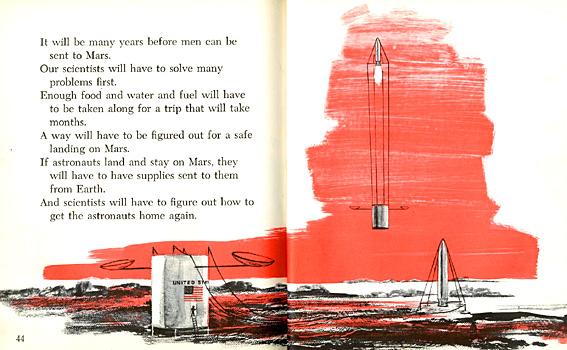
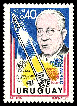
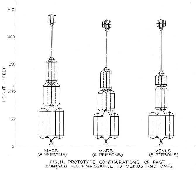

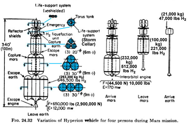
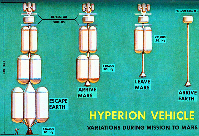
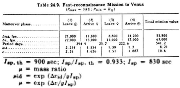
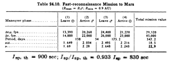
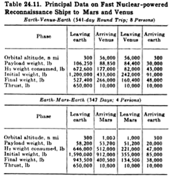


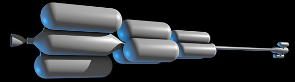


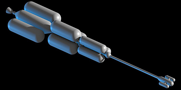
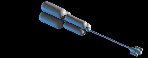


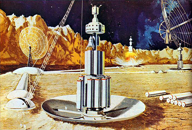


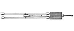


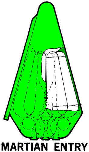
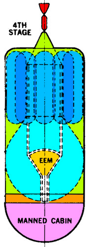


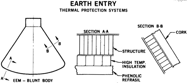


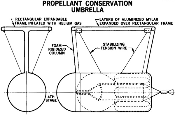
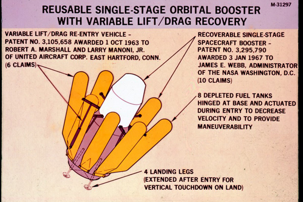
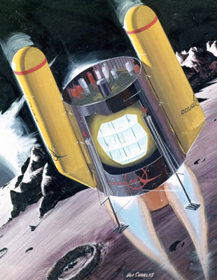

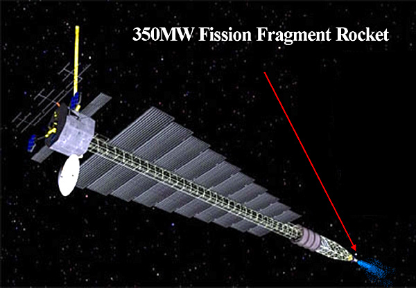
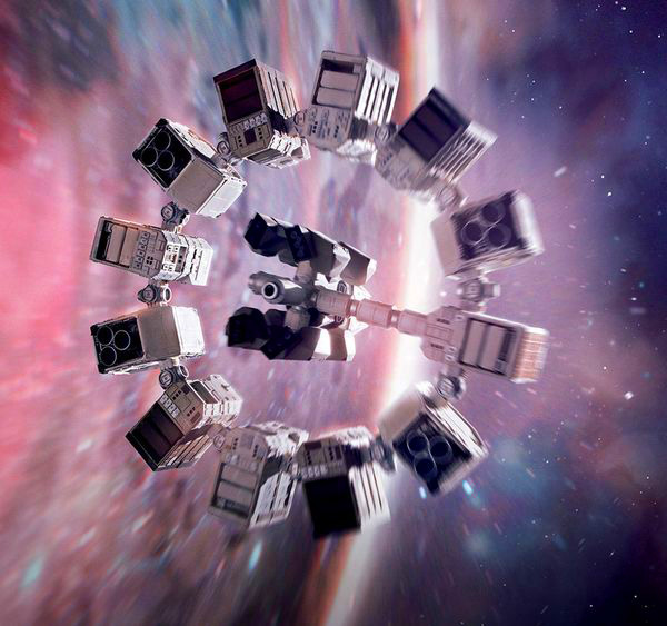
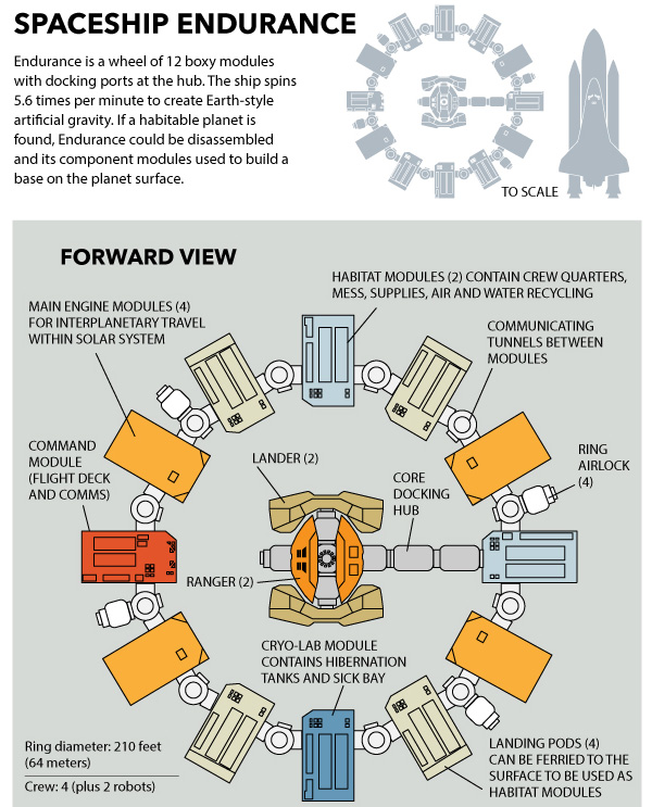
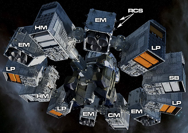


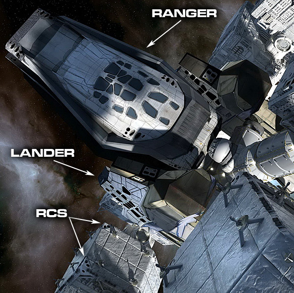

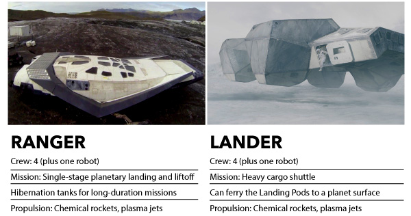


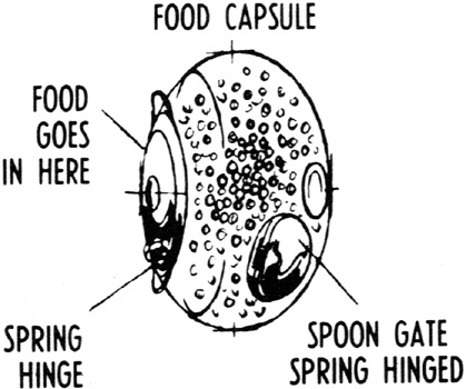
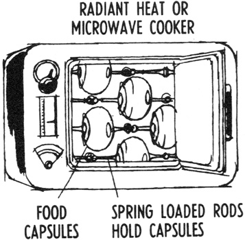


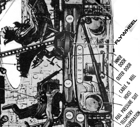
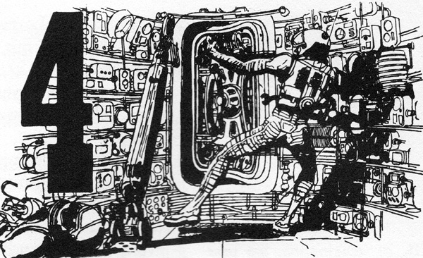

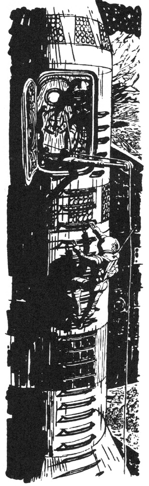
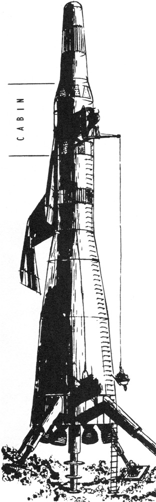

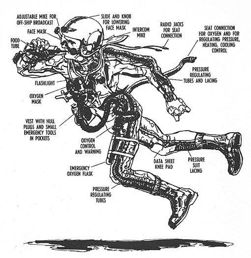
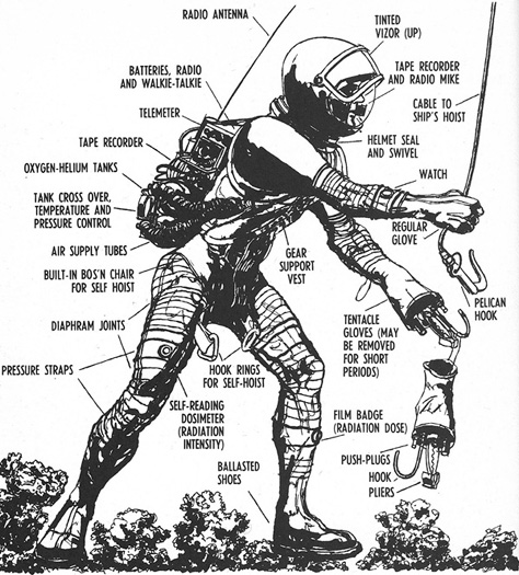

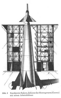
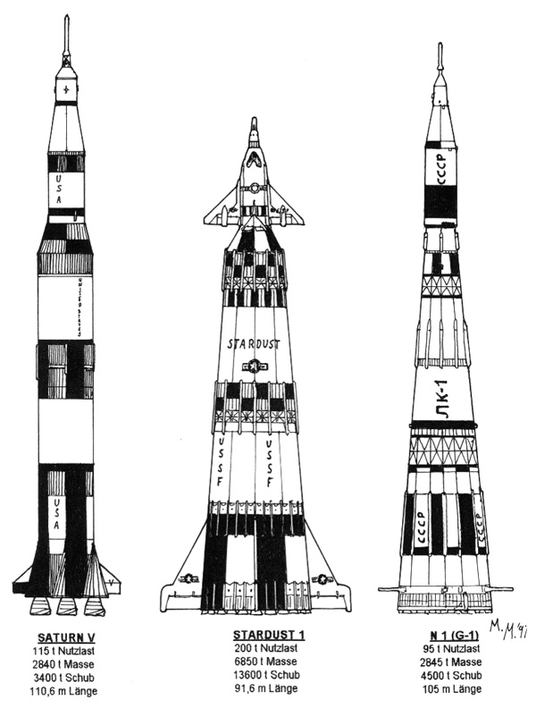

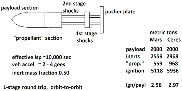
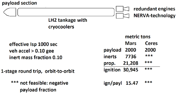
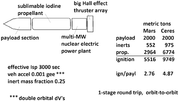

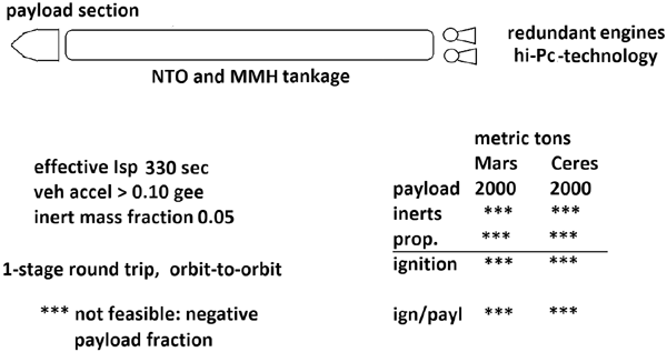


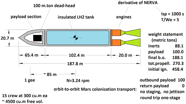
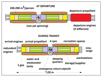


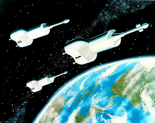


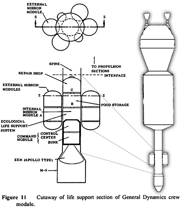
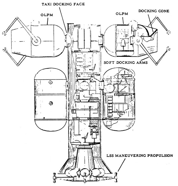
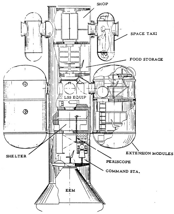


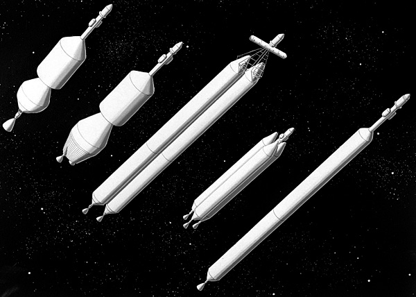
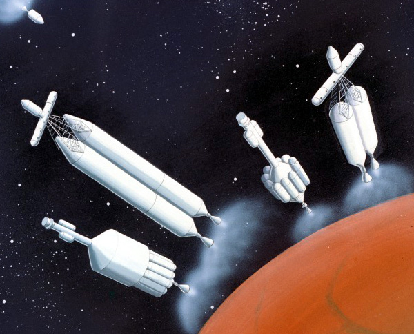
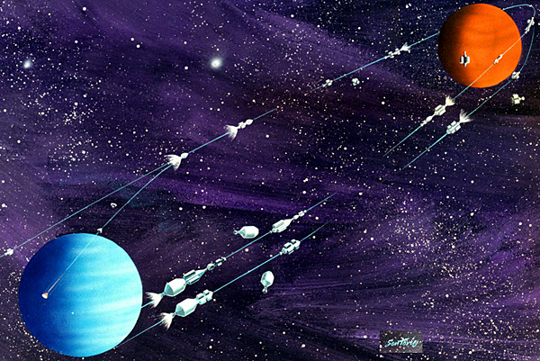

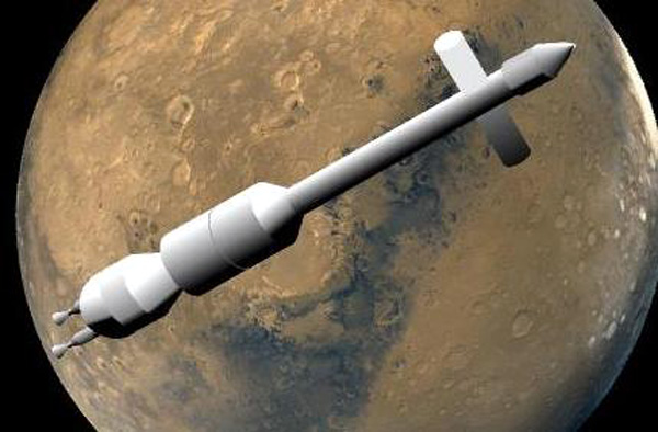
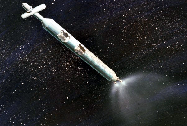
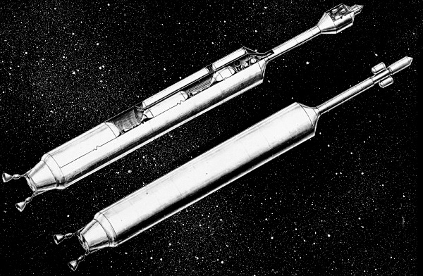


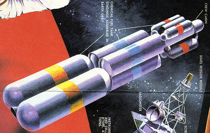


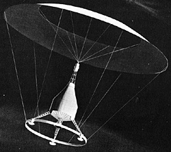
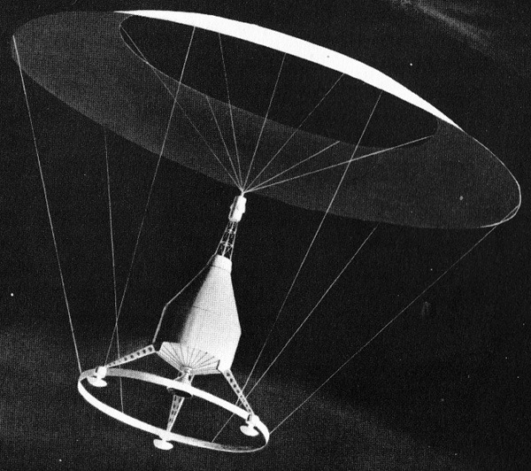
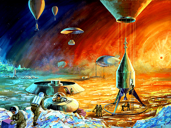
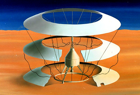
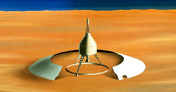
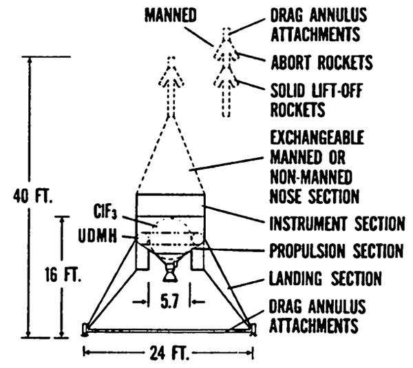
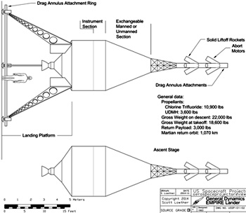
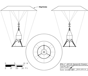

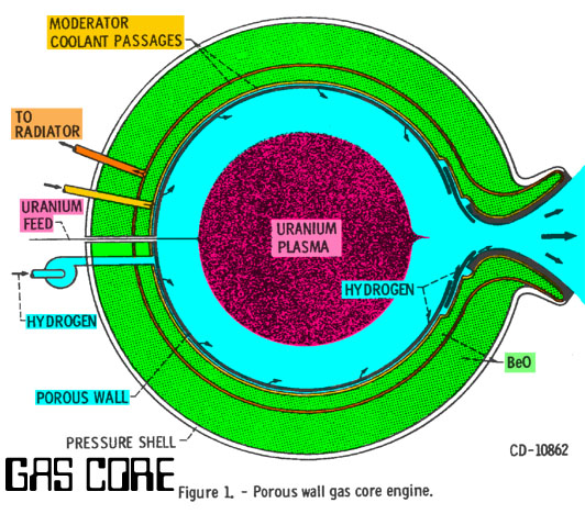
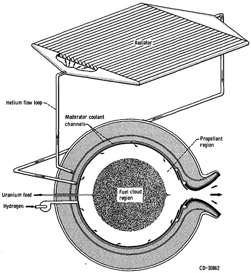
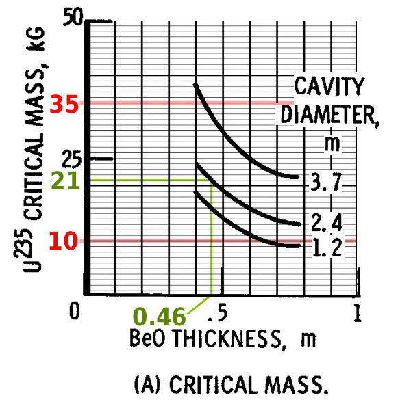
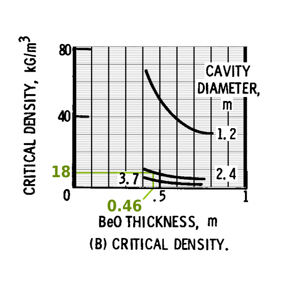
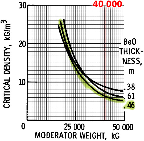
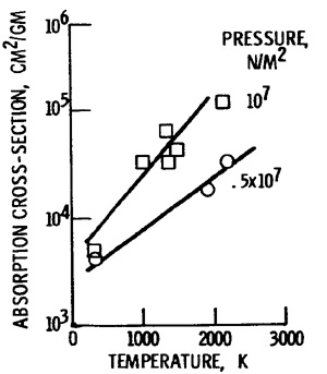
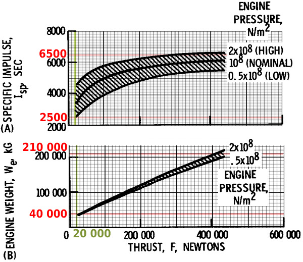
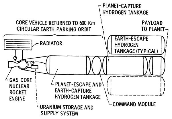


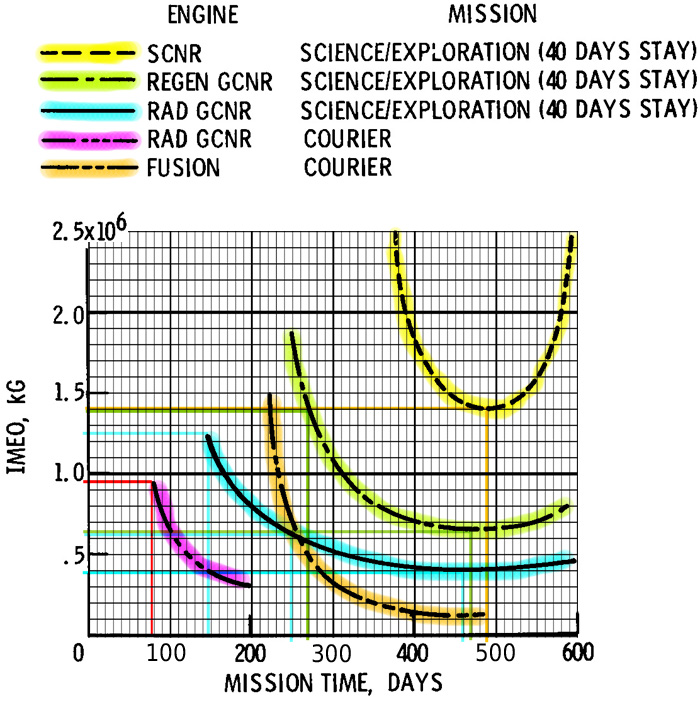
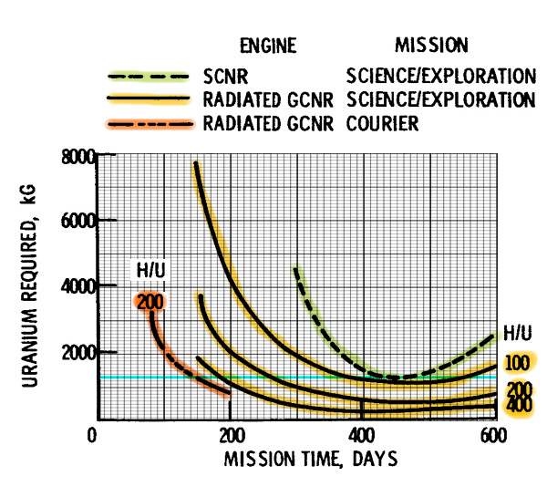
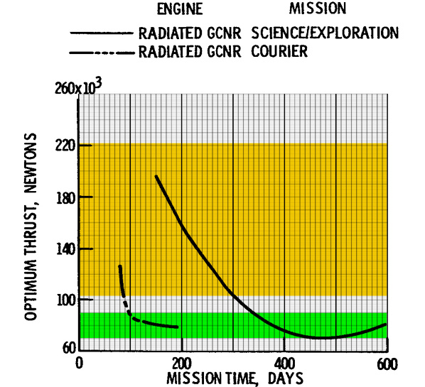
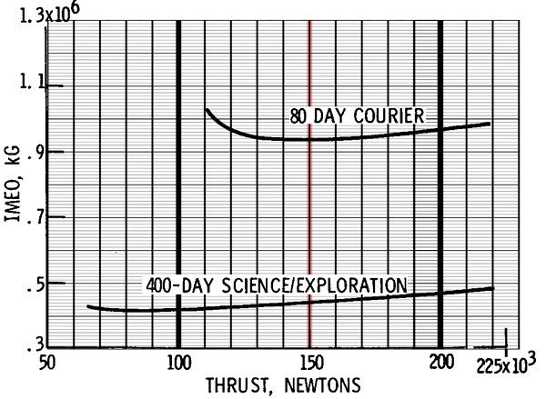
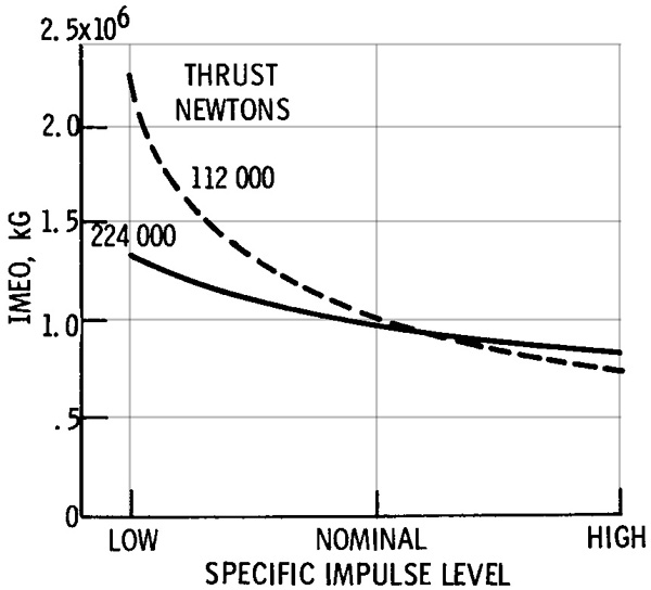
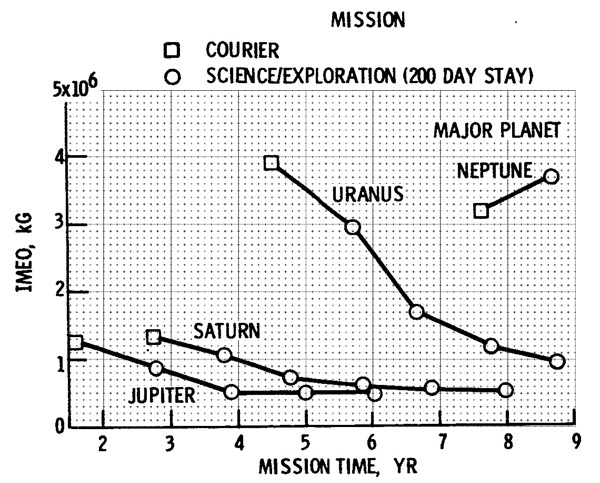
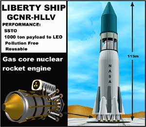
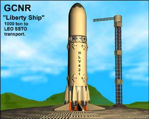


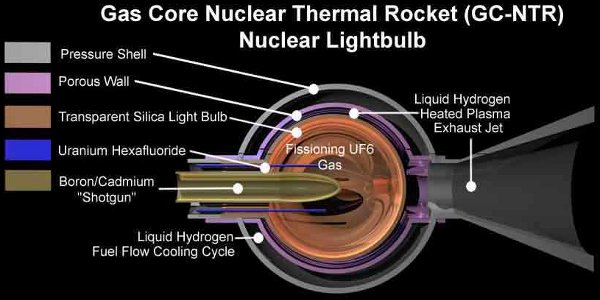

