These are some spacecraft designs that are based on reality. So they appear quite outlandish and undramatic looking. In the next page will appear designs that are fictional, but much more breathtaking. Obviously the spacecraft on this page are all NASA style exploration vehicles, they are not very suited for interplanetary combat (well, most of them at least).
Many of these spacecraft have a table of parameters. You can find the meaning of many of them here. Numbers in black are from the documents. Numbers in yellow have been calculated by me using the document numbers, these might be incorrect.
Like most nuclear-electric propulsion ships, the low acceleration is a problem when passing through Terra's Van Allen radiation belts. Prolonged exposure of astronauts to the radiation belts is very dangerous. Therefore ship is started off under remote control with no crew aboard. After about four months, the ship has finally exited the belt. Then and only then the crew rides a chemically powered Earth crew return vehicle (ECRV) which darts through the radiation belts and does a rendezvous with the ship.
The low acceleration also puts a draconian limit on how much payload can be carried. This means the mission cannot lug along a heavy Mars lander. The mission does a thorough exploration of the Martians moons Phobos and Deimos, while the astronaut look longingly at Mars: so close yet so far.
RASC NEP MARS MISSION
Abstract
The Revolutionary Aerospace Systems Concepts (RASC) team, led by the NASA Langley Research
Center, is tasked with exploring revolutionary new approaches to enabling NASA to achieve its strategic
goals and objectives in future missions. This paper provides the details from the 2004-2005 RASC study
of a point-design that uses a high-power nuclear electric propulsion (NEP) based space transportation
architecture to support a manned mission to Mars. The study assumes a high-temperature liquid-metal
cooled fission reactor with a Brayton power conversion system to generate the electrical power required
by magnetoplasmadynamic (MPD) thrusters. The architecture includes a cargo vehicle with an NEP
system providing 5 MW of electrical power and a crewed vehicle with an NEP system with two reactors
providing a combined total of 10 MW of electrical power. Both vehicles use a low-thrust, high-efficiency
(5000 sec specific impulse) MPD system to conduct a spiral-out of the Earth gravity well, a low-thrust
heliocentric trajectory, and a spiral-in at Mars with arrival late in 2033. The cargo vehicle carries two
moon landers to Mars and arrives shortly before the crewed vehicle. The crewed vehicle and cargo
vehicle rendezvous in Mars orbit and, over the course of the 60-day stay, the crew conducts nine-day
excursions to Phobos and Deimos with the landers. The crewed vehicle then spirals out of Martian orbit
and returns via a low-thrust trajectory to conduct an Earth flyby. The crew separates from the vehicle
prior to Earth flyby and aerobrakes for a direct-entry landing.
Introduction
This paper details a Revolutionary Aerospace Systems Concepts (RASC) study investigating a highpower
nuclear electric propulsion (NEP) space transportation architecture to support a manned mission to
Mars. The RASC project, led by the NASA Langley Research Center, is tasked with exploring
revolutionary new approaches to enabling NASA to achieve its strategic goals and objectives in future
missions. For this study, two vehicle concepts were designed, both using a high-power NEP system with
Brayton power conversion and magnetoplasmadynamic (MPD) thrusters. The first vehicle is the Mars
Transfer Vehicle (MTV) which carries the crew from the Earth to Mars and back again. The second
vehicle, the Cargo Transfer Vehicle (CTV), delivers additional cargo necessary for the mission from the
Earth to Mars.
This paper details one of the four space transportation architectures selected by the 2004-2005 RASC
Mars Obiter Study for analysis. The other three investigated were nuclear thermal propulsion (Borowski,
Packard, and McCurdy, 2006), NEP with Rankine power conversion, and chemical propulsion. In order
for the architectures to be compared across an even playing field, all four started with the same mission
and payload assumptions. The mission consisted of a split profile with the cargo elements sent out on one
vehicle and the crew sent out on a second vehicle. Each transportation architecture in the RASC study
assumed the same cargo and crew payloads. These study requirements led to a mission that was not
optimized specifically for an NEP system.
Vehicle Configurations
Mars Transfer Vehicle (MTV)
Figure 1.—Mars Transfer Vehicle. click for larger image
In order to provide the required artificial gravity for the crew during the Trans-Mars Injection (TMI)
outbound and Trans-Earth Injection (TEI) inbound trajectory legs, the Mars Transfer Vehicle was
configured to allow a rotation about the center of gravity. The crew is located in an inflated
Transportation Habitat (TransHab) at one end of the NEP vehicle while the Brayton power conversion
system and the nuclear reactors are located at the other end. To minimize the translation of the center of
gravity over the mission, the LH2 tanks are located at the center of the vehicle configuration. The MTV
uses two reactors, each providing 5 MWe, and a total of four Brayton power conversion units. There are
two thruster arms with four 2.5 MWe MPD thrusters (two operational, two spare) on each arm. Each
thruster arm has a radiator to reject heat from the power processing units (PPU). The total planform area
of the PPU radiators is 136.7 m2 (273.4 m2 effective radiating area). Six LH2 tanks that are 7.6 m in
diameter and 19 m long occupy the middle truss section of the vehicle and store the 279.4 MT of
propellant. The main radiator is comprised of two sections of double-sided flat panels attached to the
center truss structure on either side of the propellant tanks due to center of gravity requirements. The total
planform area of the main radiator is 2722 m2 (5444 m2 effective radiating area). The MTV is 182 m long
and must be assembled in orbit. The configuration of the MTV is shown in figure 1.
Cargo Transfer Vehicle (CTV)
Figure 2.—Cargo Transfer Vehicle. click for larger image
The Cargo Transfer Vehicle is modeled after the NEP configuration used in the 2002 RASC Callisto
mission entitled HOPE (McGuire, et al., 2003, and Borowski et al., 2003). Since the cargo vehicle does
not require the artificial gravity spin, the propellant tanks are located at the far end from the reactor to
prevent splitting up the radiator into two sections. This avoids having the hot heat-rejection fluid routed
around the cryogenic tanks, as is required in the MTV configuration. Like the MTV, the CTV has doublesided
radiator panels attached to the central truss structure of the vehicle. The total planform area of the
main radiator is 1361 m2, which provides 2722 m2 effective radiating area. The CTV uses one reactor and
two Brayton power conversion units to provide 5 MWe power. The four 2.5 MWe MPD thrusters are
mounted on the outside of the truss section that contains the propellant tanks with two thrusters, one of
which is a spare, on each side. The total planform area of the PPU radiators is 273.4 m2 (546.8 m2
effective radiating area). The CTV only has two of the 7.6 m diameter, 19 m long LH2 tanks, storing the
63.9 MT of propellant. The CTV is 127 m long and, like the MTV, must be assembled in orbit. The
configuration of the CTV is shown in figure 2.
Assumptions
Mission Assumptions and Outline
The RASC Mars Orbiter mission was configured as an opposition class (short stay) Earth-to-Mars
round-trip mission. A crew of six is deployed to Mars, but does not perform any Mars surface operations.
Rather, they perform two nine-day excursions to Phobos and Demos before returning home to Earth. The
total stay-time in Mars orbit is 60 days. The components of the NEP stages of both vehicles are launched
on heavy-lift Magnum expendable launch vehicles (ELVs) and assembled in a circular Low Earth Orbit
(LEO) at 1000 km altitude and 28.5° inclination. The Magnum is assumed to be capable of delivering
80 MT into LEO in a payload shroud 7.5 m wide by 30 m long.
The CTV conducts a spiral escape from Earth and follows a low-thrust trajectory to Mars to predeploy
two moon landers (for landing on Phobos and Deimos) in Mars orbit prior to the crew’s arrival.
After assembly and checkout, a second NEP stage with the TransHab begins the spiral escape from LEO.
After the NEP stage has cleared the Van Allen belts and is ready to escape Earth, the crew is launched on
a smaller ELV (Delta IV Heavy class) in an Earth crew return vehicle (ECRV) and docks with the NEP
stage in a high orbit. At this point, the mated NEP stage with the inflated TransHab and ECRV is referred
to as the MTV. The MTV uses the reaction control system (RCS) thrusters to spin the MTV end-over-end
upon Earth escape to provide artificial gravity (38 percent of Earth gravity, equal to Mars gravity) to the
crew in the TransHab module. The MPD thrusters provide for “side thrusting” by thrusting along the axis
of rotation. Once the MTV has reached Mars space, the vehicle performs a spin down maneuver, and the
MTV spiral captures into the same Mars orbit as the CTV.
After 60 days of Mars orbit operations, the MTV spiral escapes from Mars orbit and follows a lowthrust
trajectory back to Earth. During the heliocentric portion of the flight, the RCS thrusters induce
another end-over-end spin for artificial gravity (38 percent of Earth gravity) for the crew in the TransHab.
At Earth arrival, the ECRV separates from the MTV with the crew onboard to perform a direct-entry
aerobrake and parachute landing on Earth.
Payload Assumptions
With this mission architecture, the cargo (moon landers) is sent out on a separate vehicle than the
crew. The crew only carries enough supplies and cargo to last them through the TMI leg, the 60-day stay,
and the TEI leg of the trip. All cargo necessary to carry out moon-landing operations at the destination is
sent out on the CTV. The CTV payload consists of two moon landers designed by a team led by the
NASA Langley Research Center as part of this RASC study. These landers are designed to take three
crew on nine-day excursions to the surfaces of Deimos and Phobos, and then return to Mars orbit to
rendezvous with the MTV.
The MTV payload consists of an inflatable TransHab and an ECRV. The TransHab is similar to the
TransHab design from the Human Exploration and Development of Space (HEDS) design reference
mission 4.0 study (Joosten, 2002). The TransHab mass includes enough consumables for a 545-day
round-trip mission. Any missions with total trip times longer than 545 days must add an additional
2.45 kg/person/day to the dry-mass allocation. The crew are onboard the MTV for a total of 612 days, so
this adds 984.9 kg of consumables to the TransHab for this study. The mass of the TransHab also includes
approximately 1900 kg of water for radiation protection and 400 kg for the environmental control and
life-support system. The ECRV carries the crew during the final aerobrake for an Earth landing at the end
of the mission. Table 1 shows the masses for each of the piloted and cargo payload elements as set by the
RASC study. These masses already contain the appropriate contingency for each item, so no additional
contingency was added to the payloads in this study.
TABLE 1.—RASC 2004 PAYLOADS
Element
Mass (MT)
Vehicle
TransHab: includes food for 545 days, 6 crew
35.0
MTV
Earth crew return vehicle (ECRV)
7.0
MTV
ECRV docking structure
8.0
MTV
Two moon landers for 9-day missions
42.5
CTV
Power System
This study assumes a high-temperature, liquid-metal, fission reactor with a Brayton power conversion
system to generate the electrical power required to supply the MPD thrusters. The reactor was based on an
advanced version of the early reactor concept for the Jupiter Icy Moons Orbiter study. The fission reactors
use liquid-metal coolant loops, which operate at a temperature of about 1600 K, in order to represent
“mid-term” technology (Mason, 2001), consistent with the 2033 mission timeframe. Each reactor coolant
loop transfers heat to the Brayton system’s working fluid via a heat source heat exchanger (HSHX),
producing a Brayton turbine inlet temperature of 1500 K. The Brayton unit includes a recuperator to
improve system efficiency by pre-heating the working fluid from the compressor outlet with the turbine
exhaust before it reaches the gas cooler. The recuperator reduces the heat load of both the gas cooler and
the HSHX, which in turn reduces the size of the radiators and the reactor. The heat rejection system uses a
pumped NaK working fluid to remove heat from the Brayton working fluid via the gas cooler and
transfers that heat to the radiator panels via water heat pipes. A turbine inlet temperature of 1500 K
requires a very high-temperature turbine blade material (possibly ceramic) or active cooling of the blades,
and a reactor temperature of 1600 K necessitates the use of refractory metals or other high temperature
material for the reactor. A schematic of the Brayton power conversion system is shown in figure 3.
The MTV uses two reactors sized to provide 5 MWe net electrical power, each. Neutron interactions
between the two reactors were not considered. The cargo vehicle only requires one reactor sized to
provide 5 MWe net electrical power. The component masses and radiator areas for both vehicles are
presented in table 2. The reactor system includes the radiation shield, which is composed of layers of
tungsten (gamma shield) and lithium hydride (neutron shield). The MTV’s shields are much heavier than
the CTV’s due to the crew’s more stringent radiation limits. The radiator is double-sided, so heat is
rejected from both sides of the radiator panels. Because of this, the effective area for rejecting heat is
double the physical area of the radiator panels. The radiator design is described by Siamidis and
Mason (2006).
TABLE 2.—POWER SYSTEM PARAMETERS.
MTV
CTV
Reactor system mass
18088
kg
4973
kg
Brayton power conversion system mass
8748
kg
4374
kg
Heat rejection system mass
33456
kg
16728
kg
PMAD system mass
20484
kg
9648
kg
Radiator area (effective)
5444
m2
2722
m2
Radiator area (physical)
2722
m2
1361
m2
Figure 3.—Schematic of the power conversion system.
Propulsion System
This study used magnetoplasmadynamic (MPD) thrusters using hydrogen propellant. Besides
operating at a high specific impulse (ISP), the MPD thrusters also have the added advantages of a highpower
capability and a compact size. This analysis used high power MPD thrusters operating at 2.5 MWe
per thruster at a constant ISP of 5,000 sec with a thruster lifetime of 7500 hr.
The MPD thrusters use cryogenically-stored liquid Hydrogen (LH2) propellant. This mission utilized
the 2.5 MWe thrusters assumed in the 2002 HOPE study. The MTV vehicle used
four operating thrusters for a total power level of 10 MWe and had 4 non-operating spares for redundancy.
Likewise, the CTV used two operating thrusters at a total power level of 5 MWe and had two nonoperating
spares for redundancy. The mass of the thrusters is ISP dependant. Since a constant ISP was used
in this analysis, the mass of the thrusters was calculated using the system alpha (mass/kWe) for an ISP of
5000 sec. The thrusters were run at an ISP of 5000 sec due to higher efficiencies at this specific impulse.
See figure 4 for the dependency of system alpha and MPD thruster efficiency versus operating ISP.
One power processing unit (PPU) and one radiator are assumed per thruster. The system alpha of the
PPU and radiator is assumed to be 2.5 kg/kWe. This included the mass for the power conditioning at the
turbine (transformer to increase the voltage to 1 kV), the 1 kV transmission line, the PPU to convert
power at the other end, and the Parasitic Load radiator (PLR) to reject waste heat. The sink temperature
is assumed to be 250 K at Earth orbit for a worst-case sizing. The effective radiator areas for the two
vehicles were: CTV = 273.4 m2 for a rejection of 5 MWe, and MTV = 546.8 m2 for a rejection of
10 MWe.
Figure 4(a) Near term MPD thruster alpha
Figure 4(b) Near term MPD thruster system efficiency
Trajectory
Both the MTV and the CTV begin in LEO at 1000 km altitude, spiral out from the Earth, and
follow a low-thrust trajectory to Mars. The CTV captures into a 24.65-hr period Mars orbit (radius of
periapse = 3643 km, radius of apoapse = 37,186 km, orbital period = one Martian day). The MTV spiral-captures
into the same Mars orbit 12 days later. After a 60-day stay at Mars, the MTV returns the crew to
Earth on a flyby trajectory. The crew aerobrakes at Earth in the ECRV for a direct-entry that is
constrained to 13 km/sec at 125 km altitude. The trajectories for the vehicles were optimized using the
VARITOP trajectory optimization program. The trajectory for the MTV and CTV are
shown in figure 5. The dates and times of each mission phase as well as the total mission time and total
crew time (for the MTV) are shown in table 3.
click for larger image
Figure 5a.—CTV trajectory.
Figure 5b.—MTV trajectory.
Figure 6.—Effect of trip time on the minimum distance to the Sun.
The study requirements on the total round-trip time and stay time at Mars were not optimal for an
NEP mission and led to a close approach to the sun (0.41 AU) in the return trajectory. Such a close
approach to the sun could require additional shielding to protect the crew, the power system, and the
electronics; however, these effects were not included in this study. VARITOP was used to determine how
the trip time affected the closest approach to the Sun for varying propulsion specific masses. While the
propulsion specific mass does not have much of an effect, figure 6 shows that increasing the trip time
actually decreases the closest distance to the Sun. Reducing the trip time could be accomplished by
increasing power and/or reducing ISP, however, this would raise the power or propulsion system masses.
These trade-offs were not performed as part of this study. Since the MTV passes within the orbit of Venus
(0.7233 AU), a Venus flyby may be able to improve the trip time and/or the closest approach to the Sun.
A preliminary investigation using a Venus flyby, subject to the RASC mission constraints, did not show
any improvement to the trip time. Similarly, another mission profile using a stay time at Mars longer than
60 days might allow for a more favorable return trajectory, but this was beyond the scope of this study,
since the RASC mission requirements did not allow for changing the Mars stay-time.
Mission Mass Summary
The mass breakdown for the MTV and CTV is shown in table 4. A common contingency factor of
25 percent was applied to all dry masses other than the RASC payloads in this analysis in order to get a
final mass with contingency. A 1 percent contingency was applied to the LH2 propellant masses.
click for larger image
Conclusion
This study has developed a space transportation architecture based on high-power nuclear electric
propulsion using Brayton power conversion and magnetoplasmadynamic propulsion to support a manned
Mars mission. The architecture consists of a cargo transfer vehicle with one 5 MWe fission reactor and a
Mars transfer vehicle with two 5 MWe fission reactors. The RASC study fixed the mission parameters to
investigate the performance of 4 different technological approaches to accomplishing the mission.
Unfortunately, these mission parameters were not optimal for this architecture and led to several
difficulties. The Mars Transfer Vehicle makes a very close approach to the sun (0.41 AU) during the
return trajectory in order to rendezvous with Earth. Adjusting the stay-time at Mars and/or utilizing a
Venus flyby could be used to increase this distance. The trajectory sequence requires the MTV to begin
thrusting before the CTV; however, this occurs before the crew is on board. The MTV similarly departs
Earth and begins the heliocentric portion of the flight before the CTV, even though the CTV arrives at
Mars, first. A better approach would be to launch the CTV on an earlier opportunity than the MTV to predeploy
the cargo in the proper orbit before any resources associated with the MTV are launched.
Phase I design was for an expendable vehicle with a 200,000-pound-thrust NERVA II engine. It was to be used for several rocket stages on their planned Mars mission vehicle.
The Phase II design is what is pictured below the Class 1 Reusable Nuclear Shuttle (RNS). It had a a 75,000-pound-thrust NERVA I engine and a payload capacity of 50 tons. NASA had an optimistic RNS traffic model calling for 157 Terra-Luna flights between 1980 and 1990 by a fleet of 15 RNS vehicles.
The little attachable crew module has a mass of 9,000 kg. The NERVA engine is 18 meters long and 4.6 meters wide, intended to fit inside a Space Shuttle's cargo bay (the propellant tank can be lofted into orbit on a big dumb booster, but a nuke requires the human supervision). The propellant tank is 31 meters long and 10 meters wide.
The RNS is assumed to have an operational life of 10 Terra-Luna round trips (before the nuclear fuel rods were totally clogged). After that the RNS is attached to a chemical booster and tossed into a remote solar orbit.
The NERVA has a 1360 kilogram shadow shield on top. The shadow shield casts a 10 degree half-angle shadow, shielding was intended to reduce the radiation exposure to 10 REM per passenger and 3 REM per crew member per round trip to Luna and back. But in addtion to the shield it also relied upon propellant, structure, and distance to provide radiation shielding for the crew. Obviously as the propellant was expended, the shielding diminished.
North American Rockwell Class 1 RNS with a stand pipe
North American Rockwell tried to solve the problem with a "stand-pipe", in which a cylindrical “central column” running the length of the main tank stood between the crew and the NERVA I engine. The central column would remain filled with hydrogen until the surrounding main tank was emptied.
McDonnell Douglas Class 1 Hybrid RNS. Note the secondary tank included in the propulsion module length. click for larger image
McDonnell Douglas Astronautics Company dealth with the radiation problem by developing a “hybrid” RNS shielding design that included a small hydrogen tank between the bottom of the main tank and the top of the NERVA I engine.
Space Shuttle in "I" formation docking nose-to-nose with class 1 RNS and giving it a re-fill. Being careful to stay within the 10° safe area cast by the shadow shield. Even then only after the RNS engines have had 48 hours for the radioactivity to cool off.
D. J. Osias, an analyst with Bellcomm, pointed out that the radiation dosage received by the astronauts riding the RNS was unacceptable. Osias stated that the maximum allowable radiation dose for an astronaut from sources other than cosmic rays of between 10 and 25 REM per year (0.1 and 0.25 Sievert). But the luckless astronaut on board the RNS would get 0.1 Sieverts every time the NERVA did a burn.
Any external astronauts (not in the cone of safety cast by the shadow shield) at a range of 16 kilometers from a RNS operating at full power would suffer a radiation dose from 0.25 to 0.3 Sieverts per hour. Osias suggested that external astronauts not approach a burning RNS closer than 160 kilometers. Which could be a problem if you are an astronaut in a lunar base when the RNS is burning to leave lunar orbit since the blasted thing orbits at an altitude of only 110 kilometers. If you are standing on the ground track of the RNS you'd better get into the radiation storm cellar.
Nowadays the yearly limit of radiation exposure for astronauts is set at 3 Sieverts, with a career limit of 4 Sieverts. Which means an astronaut piloting a RNS through 40 total burns would be permanently grounded by reaching his career limit of radiation.
All the 708 inches are to ensure the modules will fit in the Space Shuttle cargo bay (18 meters long)
Class 1 Hybrid RNS
Class 1 Hybrid RNS
Lunar Mission
There are two mission types: the 8-burn mission and the 4-burn mission.
8-burn mission disadvantage: requires 4 extra burns for change-of-plane maneuvers. This increases the required ΔV to 8,495 m/s, and reduces the payload size to 45,000 kg. Advantage: you do not have to wait for a launch window, you can launch anytime you want.
4-burn mission disadvantage: mission launch windows occur only at 54.6 day intervals. Advantage: since you are not required to perform change-of-plane maneuvers the required ΔV is reduced to 8,256 m/s and the payload size is increased to 58,000 kg.
In both of these missions, it is assumed that the full payload is carried to Luna, where the payload is dropped off EXCEPT for the 9,000 kg that is the crew module. Presumably the crew wants something to live in for the trip back to Terra.
This is a 1965 design from NUCLEAR SPACE PROPULSION by Holmes F. Crouch. It seems to be the father of the NASA Nuclear Shuttle design. According to the book, it would have a single solid-core NTR engine with a specific impulse of 1000 seconds (i.e., an exhaust velocity of 9,810 m/s) and a ΔV capability of 15,000 m/s (which implies a mass ratio of about 4.6, which is a bit over the rule-of-thumb maximum of 4.0). The book estimates that an Terra to Luna Hohmann trajectory would take about 12,000 m/s ΔV, after you add in all the change-of-plane maneuvers and added an abort reserve. This would require about 60 hours to travel from the Terra to Luna, but that can be reduced to 20 hours by spending an extra 900 m/s.
In the second diagram, the ship is shown docked to something that looks suspiciously like the Space Tug. Note that they dock nose-to-nose so the lunar shuttle vehicle can stay inside the radiation shadow area.
One really exciting nuclear rocket potiential lies in Earth-Moon transport. The Moon is 208,000 n mi from the Earth. The mission concept simply is one of ferrying back and forth between Earth and Moon terminal orbits. We can think of the ferry terminals as 300 n mi Earth orbits and 100 n mi lunar orbits.
The essence of the lunar ferry concept is presented in Figure 11-8 (the one with the Earth-Moon orbits). the lunar vehicle would do all the propulsive legwork in the the terminal orbits and between the terminal orbits. Chemical systems would be employed as shuttle vehicles at the Earth terminius and at the lunar terminus. This would permit specialization in chemical systems where they are most capable: planetary launch and entry.
The nuclear ferry would have one rocket reactor with capability for multiple reuses, in-orbit replenishment, multiple restarts, and full nozzle maneuverability. We would expect the reactor to have a proven Isp on the order of 1000 seconds. It would have proven reliability, man-rating, pilot control, and long life. We would not expect the ultimate in solid-fueled reactor technology but we should be headed in that direction.
Note in Figure 11-8 that the ferry trajectory is in the form of a "figure-8." This is because it is necessary to transfer from one gravitational force center to another. Each section of the figure-8 can be thought of as an elliptical orbit: one focus at Earth and one focus at the Moon. The two ellipses "join" each other at a transfer region which is about 85% of the distance from Earth (the crossover occurs at about 180,000 n mi from Earth or about 28,000 n mi from the Moon). When going from Earth to Moon, the transfer point is called translunar injection. When going from the Moon to Earth, the transfer is called transearth injection. The injection maneuvers actually start well in advance of the trajectory crossover.
Caution is required when interpreting Figure 11-8. It gives the impression that the launching/entry trajectories, the rendezvous/docking orbits, and translunar/transearth ellipses are all in the same orbit plane with each other. This is not the case. We are dealing with noncoplanar orbit trajectories. Furthermore, they are variable noncoplanar trajectories which change from day to day and from month to month. As a consequence, the target plane — that plane connecting the Earth and Moon centers — "corkscrews" around the major axis of the figure-8 flight path. The corkscrewing of the ferry trajectory introduces fluctuations in the ΔV requirements.
Table 11-4 Nuclear Ferry ΔV Requirements
Maneuver
Feet per second
Earth Orbit Docking
1,750
Earth-Space Plane Changes
3,500
Earth to Translunar Injection
10,000
Translunar to Lunar Orbit
3,500
Lunar-Space Plane Changes
1,500
Lunar Orbit Docking
750
Lunar to Transearth Injection
3,500
Transearth to Earth Orbit
10,000
Midcourse Corrections
500
Abort Reserve
5,000
Total ΔV
40,000
A representative summary of the round trip ΔV requirements is given in Table 11-4. This listing includes all contingencies (a lunar mission can be performed with less ΔV than table 11-4 but the risk-potential increases). Note that total ΔV is 40,000 feet per second (fps). A single stage nuclear vehicle with an Isp of 1000 sec would have a ΔV capability of nearly 50,000 fps. Hence, there is some excess ΔV available.
The unused nuclear ΔV can be applied to reducing the trip time. The normal one-way trip time for a chemical propulsion system is about 60 hours (2 ½ days). Because chemical lunar missions border on marginal ΔV capabilities, the chemical trip time cannot be reduced much below 60 hours. In the case of nuclear systems, for an additional expenditure of 3,000 fps, the one-way trip time can be reduced to 20 hours. The effect of other ΔV expenditures on trip time is shown in Figure 11-9 (not shown), It can be seen that if an attempt is made to reduce the trip time below 20 hours, the extra ΔV requirements are disproportionate to the time gained. Therefore, a value of 20 hours will be selected as the nuclear ferry time base.
If the lunar terminal orbit is 100 n mi altitude, the orbit period is about 2 hours. If the lunar terminal activities necessitate as much as two orbit periods fur completion, the nuclear ferry turnaround could be made within 24 hours of Earth departure. If two nuclear ferry vehicles were used, we could have daily service to the moon and back! All-chemical lunar rocket systems could not possibly compete with this schedule.
The advantages of reduced lunar trip time are self-evident There is reduced time of confinement of astronaut, scientific, and technical personnel to the limited quarters of spacecraft. In-transit boredom and monotony are reduced. Less life support equipment is required: less oxygen, less food, less waste disposal. There is less exposure to weightlessness and less exposure to space radiation. The less the life protection equipment required, the more transport capacity for lunar basing supplies.
In the lunar terminal orbit, all exchange activities would take place at the pilot end of the nuclear ferry. This is because the propulsion reactor would be kept idling. The major features involved are presented in Figure 11-10 (middle image above). One feature not always self-evident is the need to off-load chemical propellants from the nuclear ferry to the lunar shuttle. To make the propellaut transfer, special cargo tanks on the nuclear ferry and special piping on the chemical shuttle would be required, It is assumed that chemical propellants for the shuttle vehicle probably could not be manufactured on the Moon and therefore would have to be transported from Earth.
From NUCLEAR SPACE PROPULSION by Holmes F. Crouch (1965)
Reusable Nuclear Shuttle Class 3
The Class 1 Reusable Nuclear Shuttle (above) was designed to be a pre-assembled spacecraft launched into orbit by a Saturn V INT-21 vehicle. But the Class 3 RNS was designed to be assembled in orbit by modules boosted by the Space Shuttle. The major difference is that all the modules must be sized to fit into the Shuttle's cargo bay.
Cost Effectiveness
Spacecraft
Payload Delivered
Recurring Cost Per Flight (8 per year)
Recurring Cost Per Flight (2 per year)
(lb)
(US 1970 dollars)
Class 1 RNS (hybrid)
128,000
$73 million ($575/lb)
$76 million ($602/lb)
Class 3 RNS
108,000
$65 million ($602/lb)
$68 million ($634/lb)
Above table assumes minimum energy lunar missions, and a 20,000 pound payload return (i.e., the "return payload" is the crew habitat module and other items needed for the return to Terra).
The Class 1 has a lower dollar per payload pound, but the Class 2 can be lofted by the reusable Space Shuttle instead of throw-away Saturn heavy lift vehicles. Also the Class 1 requires a 10,000 biological radiation shield, while the Class 3 can get by with no shield but a lot of distance.
Actually, I lied: in some designs they use the "hybrid" engine, which has a cute little auxiliary tank perched on top. This makes the Propulsion modules composed of one big propulsion tank, an auxiliary tank, and a NERVA engine. A NERVA with the small auxiliary tank is just short enough to fit in a Space Shuttle cargo bay, this comes in handy if you are producing both Class 1 and Class 3 RNSs. You can use the same engine for both.
This is from McDonnell Douglas Nuclear Shuttle System Definitions Study, Phase III - Final Report - Volume II Concept and Feasibility Analysis - Part B Class 3 RNS - BOOK 2 System Definitions (1971). Thanks to Erin Schmidt for bringing this report to my attention.
The engine has a lifespan of 10 hours of total operation and 60 warm-thrust-chill cycles (I assume 10 hours at full thrust). After that it has to be disposed of, preferably into a distant solar orbit. The back of my envelope says this means roughly 10 Lunar missions before the engine is used up. The problem is that the reactor fuel elements are so clogged with nuclear poisons that they won't react any more. By this time the engine has become so radioactive that it isn't worth the effort to try to extract the fuel elements for reprocessing. Which is a pity since only 15% of the nuclear fuel has been burnt.
The NERVA has an internal radiation shadow shield, but that is a weak one just meant to protect the engine gimbals and thrust frame. To protect the crew there is an optional external shadow shield. The ship designers do their best to use liquid hydrogen propellant as radiation protection insteaad of the external shield, since the blasted shield has a mass of four metric tons.
NDICE is the NERVA Digital Instrumentation and Control Electronics. This allows the pilot to control the throttle, gimbal, and other functions. The part of NDICE that is actually mounted on the engine has a mass of 230 kg.
The engine requires up to 3.5 kilowatts to operate the NDICE, the gimbal electric motors, the turbines, control valves, reactor control drums, and whatnot.
The gimbal pivots the engine for thrust vectoring, used to change the course of the spacecraft. The engine can be pointed up to three degrees off-center in any direction. The maximum rate it can change the pivot is 0.25 degrees per second, but it takes time to get up to speed. It can only accelerate to maximum rate at 0.5 degrees per second per second.
click for larger image
click for larger image
click for larger image
click for larger image
click for larger image
PROPULSION TANK MODULE
click for larger image
This is the main propellant tank feeding the NERVA engine. The other propellant modules keep it filled.
PROPULSION MODULE
click for larger image
This is one propulsion tank module with one NERVA engine. And maybe an auxiliary tank in between if this is a hybrid propulsion module.
PROPELLANT MODULE
click for larger image
SPACE FRAME MODULE
Space Frame click for larger image
Systems Within Space Frame click for larger image
Command and Control Equipment Module
Solar Power Array click for larger image
The Space Frame is sort of the backbone of the ship. It holds the spacecraft together and helps transmit the engine thrust to all the components (instead of the components breaking off and falling to the wayside). It is perched on top of the propulsion module and has the propellant modules attached to all six sides. At the top is the command and control equipment module, along with the reaction control jets. The payload is attached to the top of the space frame.
RNS ASSEMBLED
click for larger image
click for larger image
click for larger image
Alternate click for larger image
All the 708 inches are to ensure the modules will fit in the Space Shuttle cargo bay (18 meters long)
Class 3 RNS click for larger image
Class 3 RNS
click for larger image
RADIATION
Figure 3.7-1 click for larger image
Figure 4-68
Figure 4-69
Tables 4-24, 4-25, and 4-26
The first word in the spacecraft's name is "Reusable." One of the more worrying concerns about reusing the spacecraft is the dread horror of Neutron Activation. Simply put, parts of the spacecraft that are close to the nuclear engine will gradually become radioactive. More specifically the atoms composing the engine and structural members will swollow low-energy neutron from the nuclear reactor during engine burns and thus be transmuted into radioactive isotopes. These isotopes will emit gamma-ray radiation. This wil make it read difficult to refurbish a RNS for the next trip without exposing the refurbish crew to dangerous doses of radiation.
The charts use the obsolete radiation absorbed dose unit the Rad instead of the more modern Gray. Multiply Rads by 0.01 to get Grays. Since the quality factor of gamma radiation is 1, the dose equivalent of Rem will be equal to the Rad dose (and likewise the Sievert dose will be equal to the Gray dose).
A dose of 3.5 to 3.9 Sieverts means the astronaut is "Singed". A dose over 4.0 Sieverts means the astronaut is "Cooked", which means their NASA career is over (forbidden to work at any NASA job where they might be exposed to radiation). A dose over 4.5 Sieverts is "Fried", which is LD50 (50% chance of death).
The spacecraft is assumed to have a useful life of 10 missions (due to the fission fuel elements filling up with nuclear poisons), then thrown into a radioactive disposal orbit.
Figure 4-68 shows the neutron activation radiation dose rates at various locations, starting at the final engine shut down at the end of the 10th mission. The worst is at location 3, at 0.4 Sieverts per hour. This means a Fried dose in 12 hours. Now, 417 days after final engine shut down the radiation has decayed to the point where location 3's radiation is so weak that an astronaut would have to stay there more than years to get a Fried dose.
The report is of the opinion that any astronaut refurbishment, engine swap, or other operations on the spacecraft should wait until 100 hours (102 hours) after engine shut down. This will allow the neutron activation induced radiation to die down to a less than utter suicidal level.
Table 4-24 is similar to Figure 4-68. Except the locations are different and the doses are in milliRads per hour instead of Rads per hour. 1 milliRad equals 0.001 Rad and equals 0.000 01 Sievert. "Decay Time Hours" and "Hours After Shutdown" are the same, as are the column headers (10,000 = 104)
Table 4-25 is the dosage contributed by each activated part. The values are for the case of the detector at 100 feet. And because the study authors figured things were not complicated enough, the table is in microRads per hour. 1 microRad equals 0.000 001 Rad and equals 0.000 000 01 Sievert. So for instance Table 4-24 lists the 101 shutdown dose as 13.6 milliRad and Table 4-25 lists it as 13,600 microRad.
Figure 4-69 shows the model used to calculate the doses in Figure 4-68. The model shows the location of the various components and their composition. Table 4-26 shows the percentage of the neutron activation radiation contributed by each material, figuring their in the amount of each material and its suseptibility to neutron activation.
At 10 hours after shutdown, Manganese-56 with a half-life of 2.58 hours and Copper-64, with a
half-life of 12. 8 hours account for approximately 98 percent of the total dose rate.
The stainless steel alloys have a maximum weight fraction of 2 percent Manganese and the
aluminum alloys have a weight fraction of 0.15 to 0.9 percent Manganese and 0.4 to 6.8
percent Copper.
At 100-hr decay time, many radioactive isotopes are significant: Copper-64, 12.8 hr;
Chromium-51, 27.8 days; Iron-59, 45 days; Molybdenum-99, 66 hr; Cobalt-58, 71 days; and Sodium-24, 15 hr.
The latter two isotopes are products of fast-neutron reaction. The Sodium-24 isotope results
from an (n, α) reaction with aluminum, while Cobalt-58 and Manganese-54 isotopes result from
(n,p) reactions with Nickel-58 and Iron-54, respectively. The dose rates from the stainless
steel alloys are dominated by Chromium-51 and Iron-59 isotopes, while Cu-Copper and Sodium-24 dominate
the dose rates from aluminum alloys.
At 1,000 hours, the predominant isotope is Cobalt-58, followed by Manganese-54, Chromium-51 and Iron-59.
At 10,000 hours, the Manganese-54 isotope becomes predominant, followed by Cobalt-58. The
Zinc-65 isotope emerges as relatively significant, while Iron-59 is relegated to a role of
minor importance.
Figure 5-6
Chart assumes engine is burning at full power, 1,575 megawatts
To prevent the chart from being huge, they "folded" it
For the left hand diagonal line, use the scales on the left and the bottom
For the right hand diagonal line, use the scales on the right and the top
Figure 5-7
Chart assumes separation distance of 100 feet click for larger image
Class 3 RNS
As previously mentioned when the nuclear engine is executing a burn, the radiation emitted will be very unhealthy to anything else nearby. A used RNS will emit gamma radiation due to neutron activation, but during a burn it will emit both gamma and neutron radiation.
The intensity of the radiation depends upon reactor power level, distance from the reactor, and intervening masses such as the shadow shield and ship components. Figure 5-6 indicates that even at a distance of 100 nautical miles (102 NM) the dose can be as high as 10-4 REM/sec (0.000 001 Gray/sec) which is significant but not instantly lethal.
In figure 5-7 the sharp reduction in dose rate between 0° and 15° is due to the anti-radiation shadow shield. While the shadow was designed to protect the crew in the habitat module, it will also protect a second spacecraft (as per the next diagram). The 15° line is right where the Neutron curve hits the bottom of the graph. The dose is reduced by distance as per the inverse-square law(if you double the distance the strength drops to 1/4), like all radiation.
REACTION CONTROL SYSTEM
MISSIONS
Lunar Missions click for larger image
Mars Mission
Mars Mission
Revell XSL-01
Ellwyn E. Angle photo courtesy of the Angle Family
Revell XSL-01 Manned Space Ship
Stage III Moon Ship
Engine
Pebble-bed NTR
Propellant
Liquid Hydrogen
Thrust
88,964 N
Specific Impulse
1000 sec
Exhaust Vel
9,810 m/s
Dry Mass
4,667 kg
Propellant Mass
5,584 kg
Wet Mass
10,251 kg
Mass Ratio
2.2
ΔV
7,718 m/s
Initial Accel
8.68 m/s 0.88 g
Stage II
Engine
Chemical
Fuel
Fluorine/ Hydrazine
Thrust
2,224,110 N
Specific Impulse
399 sec
Exhaust Vel
3,912 m/s
Inert Mass
83,189 kg
Payload Mass
10,251 kg
Payload
Stage III
Dry Mass
93,440 kg
Propellant Mass
122,016 kg
Wet Mass
215,456 kg
Mass Ratio
2.31
ΔV
3,268 m/s
Initial Accel
10.32 m/s 1.05 g
Stage III
Engine
Chemical
Fuel
Fluorine/ Hydrazine
Thrust
8,006,796 N
Specific Impulse
295 sec
Exhaust Vel
2,895 m/s
Inert Mass
61,961 kg
Payload Mass
225,708 kg
Payload
Stage II + Stage III
Dry Mass
287,668 kg
Propellant Mass
332,030 kg
Wet Mass
619,698 kg
Mass Ratio
2.15
ΔV
2,222 m/s
Initial Accel
12.92 m/s 1.32 g
Revell model kit #H-1800 "XSL-01 Manned Space Ship" is probably the second most sought after out-of-production space-oriented plastic model kit (the first most being Revell #H-1805 "Space Station")
Revell Inc. was a kit manufacturer who wanted to get into the act with their own space kit. As it turns out just 26 km down the road was a new company called Systems Laboratories Corporation (SLC) which was doing actual research studies to design future spacecraft. And the founder/CEO John Barnes just happened to know the head of Public Relations of Revell. He suggested that Revell might want to take a gander at their new spaceship design. Revell founder/CEO Lew Glazer couldn't believe his own luck, and promptly accepted.
Barnes gave the job to new employee Ellwyn E. Angle, telling him to design something nice just for Revell.
The kit sold quite well and Glazer was pleased. Actually it was one of Revell's best sellers for that year. Glazer was even more pleased when he realized that he could sell just the top part as a bargain-priced kit under the name "Moon ship." Angle also wrote an educational pamphlet included with the kit which I've reproduced below.
Amusingly in the episode of Men Into Space "Flare Up", the prop department used an XSL-01 plastic model for the advanced Soviet spacecraft.
Glazer commissioned Angle to make a second design, for a space station. Sadly this kit did not do nearly as well, which is a pity because it is nice kit. Or so I've heard, it is so rare that I've never seen a vintage kit offered at a price I could afford. The reasons for failure were varied: it was so big it was quite a bit more expensive ($4.98 as compared to $1.98, about $44.48 in 2018 dollars), and after Sputnik went up people had soured on space. So Revell commissioned no more kits from Angle.
The XSL-01 (eXperimental Space Laboratory) was a classic "arrow" design. That is, it looked like sharp pointy thing perched on a rod. The pointy thing was the winged Moon Ship that actually performed the mission: LEO ⇒ lunar transit ⇒ lunar orbit ⇒ lunar landing ⇒ exploration ⇒ lunar liftoff ⇒ Terra transit ⇒ aerobraking ⇒ Terra landing.
The rod was a two-stage rocket whose sole purpose was just to get the Moon Ship (stage three) from the ground into low Terra Orbit. "Halfway to Anywhere" strikes again. The original design had stage I and II chemical rockets using liquid oxygen and and alcohol.
For the model kit, Angle had to shorten the stage I and II tanks to keep the kit within Revell's planned price range. The booklet says the overall length is 34 meters, I'm not sure if that with the shortened stages or not. The instruction sheet says the scale is 1/8 or 0.125 = 1 foot (1 mm = 0.08 m). Using calipers on my Moon Ship's astronauts makes this scale seem reasonable. The distance from the Moon Ship's nose to the rear of the wings is 12.0 meter on this scale. I do not have the XSL-01 model, but measuring from a couple of different images I get an overall length of 27.9 meters. Make of that what you will.
With the truncated tanks Angle was forced to use the more powerful (but insanely dangerous) oxidizer Liquid Fluorine, which has probably killed more rocket researchers than any other chemical. Or any chemist for that matter. It is sometimes used with liquid methane when you need the specific impulse of liquid-oxygen/liquid-hydrogen but cannot afford the voluminous fuel tanks required. Angle then doubled-down on danger by using hydrazine instead of methane. Hydrazine is not quite as deadly as its close cousin Unsymmetrical dimethylhydrazine(which Troy Campbell calls "explosive cancer") but it is certainly bad enough.
The Moon Ship (stage III) does not play around with feeble chemical engines, it has a full blown nuclear thermal rocket. When I look at the mass budget, I find it difficult to believe it also has a full blown radiation shadow shield thick enough to protect the crew from a lethal dose. Even if it did, the Moon Ship's wings and propellant tanks stick outside the shadow, so they will backscatter harmful radiation all over the place.
Upon return to Terra, spacecraft uses aerobraking by a series of braking ellipses over a period of two days. The drags covering the hydrogen propellant tanks do most of the work. When the velocity slows enough, the drags and the propellant tanks are jettisoned. It then does a dead-stick landing using the wings and aerodynamic control surfaces exactly like the old NASA Space Shuttle.
According to this diagram, stage I and II use liquid oxygen and alcohol fuel. Stage III separates after a 500 second burn. On stage III the aft pods act as aerobraking drags when returning to Terra. They also store the liquid hydrogen propellant for the nuclear engine.
Sketch by Ellwyn Angle
Instrument cone is open, allowing the mercury boilers to start generating power
from model kit instruction booklet
from model kit instruction booklet
The column SPEED — MILES PER HOUR is a running total. The final value is the delta-V total for the first burn, the one that takes the spacecraft from the launch pad to Trans-Lunar-Insertion. This requires two chemical stages and a short burn from the nuclear engine on the Moon Ship.
The numbers in pink look like an error to me. It is impossible to have a larger propellant pounds than gross weight pounds, unless the inert mass is negative or something impossible like that. I swapped the positions of the numbers for my calculations.
21,600 miles per hour is six miles per second. This is referred to in the flight program below, at +1380 seconds. That's how I know that the final delta-V value is only for the first burn, not the entire mission.
Here is the above table in metric, with Atomic Rocket standard headers:
Stage
Wet Mass (kg)
Propellant Burnt (kg)
ΔV Totals (m/s)
Thrust (N)
I
616,698
332,030
2,222
8,006,796
II
215,456
122,016
5,490
2,224,110
III
10,251
5,584
9,656
88,964
The ΔV Total of 9,656 m/s means Stage III (the Moon Ship) contribution was 1,945 m/s.
In addition, the Moon Ship also has to land on Luna (~2,470 m/s), lift-off from Luna (~2,222 m/s), and do a Trans-Terra Insertion (~1,076 m/s). I'll assume that it need negligable delta V to aerobrake. So more delta-V will be needed than 1,945 m/s.
This means it will need a total of about 1,945+2,470+2,222+1,076 = 7,713 m/s.
Assuming the nuclear engine has a maxed-out specific impulse of 1,000 seconds, it can manage this with a mass ratio of 2.2. This means 4,667 kg of dry mass and 5,584 kg of liquid hydrogen propellant (I tried with a more reasonable 800 second nuclear engine, but the mass ratio got ugly).
I doubt 5,584 kg of hydrogen will fit in the small external aerobrake drags since liquid hydrogen is annoyingly non-dense. The entire rear of the Moon Ship is probably full of LH2 as well.
Braking ellipses is aerobraking on the installment plan. Each aerobraking pass slows you down a little more. In two days you will be slow enough to actually land at the airfield.
This is from PROJECT ROVER U.S. Nuclear Rocket Development Program, Hearings before the Committee on Science and Astronautics U.S. House of Representatives Eighty-Seventh Congress February 27, 28, March 1, 6, and 7, 1961.
Reuseable Interplanetary Transport (RITA) was a design for a nuclear powered transport rocket developed by the Douglas Aircraft Co. RITA-A was the nuclear second stage of a two-stage rocket, the first stage was a chemically powered Saturn S-I. RITA-B on the other hand was a single-stage rocket, and was totally nuclear. Douglas optimistially thought these could be up and running by 1970.
Just like SpaceX, Douglas knew that the key to opening up space was rocket reusability. You cannot amortize the cost of a rocket over multiple uses if it is only used once then thrown away.
Cargo transport cost for lunar round trip
The above diagram shows how the transport cost falls as the specific impulse rises. Note that the cost scale is logarithmic. The RITA icon is at a cost of 5 while the chemical is at a cost of 500, not a cost of 3.5. The point is that the price of re-usable nuclear can drop low enough so it is close to that of a terrestrial DC-8 aircraft.
Lunar payload delivery cost comparison
Of course these are direct operating costs, the development cost is not shown in the diagram and are likely to be huge. As is developing anything with the word "nuclear" in its description. The above diagram compares chemical and nuclear with the development cost folded in. Surprisingly the direct operating cost of RITA is so low that delivering less than 400 tons to the lunar surface will fully amortize the estimate $1 billon (in 1960 dollars) in RITA development cost. The diagram also assumes that the chemical engine development prices are fully half that of the nuclear engine, which is probably unjustifiably optimistic to the benefit of the chemical system.
RITA is also a versatile design:
Orbital truck to carry objects into and out of specific orbits
So one is getting lots of value out of each development dollar.
RITA-A and RITA-B
RITA-A
RITA-A
The RITA-A uses the original one-lung ROVER engine. So it needs a chemical stage in order to make it to LEO with a halfway decent payload. There it can perform orbital or lunar missions, but not interplanetary.
RITA-A PAYLOAD
Single Stage
Atop Saturn First Stage
Orbital
6,800 kg
39,000 kg
Lunar
cannot
4,500 kg (17,000 kg w/1 refuel)
RITA-B
RITA-B size comparison
RITA-B
The shape is the classic tear-drop shape of the aerobraking Apollo command module. When leaving
Terra it moves through the atmosphere pointy-nose-first for minimum friction. When aerobraking for a landing it leads with its broad rump for maximum friction and braking power. The rump is thoughtfully coated with a heat shield. The drag-weight ration is so high that it doesn't need a massive heat shield, a modest one will do. The deceleration will also be less than 2 g's, so the crew and any soft cargo will not be damaged.
The nuclear engine is located within the outer tank cluster and below a central fuel tank. This location allows for a clean aerodynamic geometry (for both lift-off and landing) and obviates the need for awkward support structures for landing (i.e., no need for legs to prevent the weight of the spacecraft from crumpling a protruding engine like it was a used cigarette butt). Eight inflatable bags located around the periphery of the heat shield stop the blasted RITA from wobbling on its base like a freaking Weeble.
The report did note that while initial RITA-As would use the Rover engine that was being developed, it would be best if the engine for the RITA-Bs could be upgraded to a thrust more like 890,000 Newtons without adversely affecting the specific impulse or the thrust-to-weight ratio.
The design above uses either a cluster of four 890,000 N engines, or a single 3,300,000 N engine.
RITA-B
The top of the RITA is the crew habitat module and payload bay. As with many nuclear rocket designs, the arrangement puts most of the propellant tankage in between the crew and the radioactive engine. This adds additional radiation shielding without cutting into the payload budget. The payload bay is also positioned to protect the crew.
Those tubes on the base are part of the reaction control system. If you look at the full ship image, you see that even though they are on the base of the habitat module, they are exposed due to fluting on the propulsion system.
RITA-B PAYLOAD
Single Stage
Orbital
73,000 kg
Lunar
11,000 kg (27,000 kg w/1 refueling)
Early Interplanetary
20,000 kg w/multiple refueling
DSV Ringmaster
John Varley's Gaea trilogy of SF novels are
reasonably hard, given that they are set in the interior of a largish space colony around Saturn which is not just made of organic technology but sentient organic technology.
In the first novel the protagonists travel to Saturn in a NASA space mission. Their spacecraft is the Deep Space Vessel Ringmaster. The more interesting details are sadly lacking, but its propulsion system must be potent and either fission or fusion. Because it has a radiation shadow shield and it made the Terra-Saturn voyage in eighteen months instead of the six years a Hohmann trajectory would take.
TITAN
artwork by R. Courtney
Her room was at the bottom of the carousel, midway between ladders three and four. She followed Gaby around the curving floor, then pursued her up the ladder.
Each rung was a little easier than the last until, at the hub, they were weightless. They pushed off from the slowly rotating ring and drifted down the central corridor to the science module. SCIMOD in NASA-ese. It was kept dark to make the instruments easier to read, and was as colourful as the inside of a jukebox. Cirocco liked it. Green lights blinked and banks of television screens hissed white noise through confetti clouds of snow. Eugene Springfield and the Polo sisters floated around the central holo tank. Their faces were bathed in the red glow.
Ringmaster was an elongated structure consisting of two main sections joined by a hollow tube three meters in diameter and a hundred meters long. Structural strength for the tube was provided by three composite girders on the outside, each of which transmitted the thrust of one engine to the life system balanced on top of the tube (meaning there are three engines, one for each girder).
At the far end were the engines and a cluster of detachable fuel tanks, hidden from sight by the broad plate of the radiation shield which ringed the central tube like the rat guard on the mooring line of an ocean-going freighter. The other side of that shield was an unhealthy place to be. (radiation means fission or fusion engine. Or antimatter but that seems unlikely)
On the other end of the tube was the life system, consisting of the science module, the control module, and the carousel.
Control (CONMOD) was at the extreme front end, a cone-shaped protuberance rising from the big coffee can that was SCIMOD. It had the only windows on the ship, more for tradition than practicality.
The Science Module was almost hidden behind a thicket of instrumentation. The high-gain antenna rose above it all, perched on the end of a long stalk and trained on Earth. There were two radar dishes and five telescopes, including Gaby’s 120-centimeter Newtonian.
Just behind it was the carousel: a fat, white flywheel. It rotated slowly around the rest of the ship, with four spokes leading up from the rim.
Strapped to the central stem were other items, including the hydroponics cylinders and the several components of the lander (the Satellite Excursion Module or SEM): life system, tug engine, two descent stages and the ascent engine.
The lander had been intended for exploring the Saturn moons, in particular Iapetus and Rhea. After Titan—which had an atmosphere and was therefore unsuited for exploration this trip—Iapetus was the most interesting body in the neighborhood. Until the 1980’s, it had been significantly brighter in one hemisphere, but it had changed over a twenty-year period until its albedo was nearly uniform. Two troughs in the graph of luminosity now occurred at opposite points on its orbit. The lander had been designed to discover what caused it. (Novel takes place approximately in the year 2055)
Now that trip had been scrapped in the face of the much more compelling object called Themis (the space colony).
Ringmaster resembled another spaceship: the fictional Discovery, the Jupiter probe from the classic movie 2001: A Space Odyssey. It was not surprising that it should. Both ships had been designed from similar parameters, though one sailed only on celluloid. Cirocco was EVA to remove the last of the solar reflection panels which wrapped the life system of Ringmaster. The problem in a space vehicle is usually one of disposing of excess heat, but they were now far enough from the sun that it paid to soak up what they could get.
Celestia add-on created by Selden click for larger image
RM-1 Lunar Reconnaissance Craft
RM-1
Propulsion
chemical
ΔV (estimated)
2,800 m/s
Specific Impulse (estimated)
314 s
Length
23 m
Max Width
7.4 m
Crew
4
This design was the result of a nice bit of collaboration between Walt Disney and Dr. Wernher von Braun (architect of the Saturn V).
Disney's TV show "The Wonderful World of Color" had decades of material for the segments Fantasyland, Frontierland, and Adventureland, but zero for Tomorrowland. Disney's concept executive Ward Kimball had been following Collier magazine's awe inspiring series Man Will Conquer Space Soon, detailing von Braun's plans for manned spaceflight. This series would be perfect for a set of Tomorrowland episodes.
Kimball quickly discovered that he was in over his head, but Disney allowed him to hire technical experts. Kimball proceeded to enlist the main tech experts from the Collier's series: Willey Ley, Heinz Haber, and of course Wernher von Braun. Kimball realized that when it got down to the fine details, you'd have to get help from The Man himself. When Kimball made a tentative inquiry to von Braun, the latter jumped in with both feet. von Braun desperately needed favorable publicity for his Moon mission. The Colliers article reached barely three million viewers. A Disney show could reach tens of millions!
The RM-1's mission was a simple loop around Luna, with no landing (the same as the Apollo 8 mission). The only things you needed was a few days of life-support for the crew, and about 2,700 m/s of delta V. And a bit under 100 m/s to brake back into Terra's orbit. So the spacecraft can be built out of bits and pieces of the existing cargo and passenger ferry rockets.
The front part of the RM-1 was the top stage of the passenger ferry minus the wings but including the passenger section, life support, and engine. Six standard propellant tanks were attached to increase the delta V to 2,800 m/s. When the extra tanks were empty, they were retained as protection from meteors (unnecessarily, meteors are not that common), but jettisoned just before the braking burn into Terra orbit to reduce the ship's mass.
On a nose spike was attached a nuclear reactor, for on-board power. A conical shadow shield protects the crew from reactor radiation. The reactor is ludicrously tiny, in reality it would be quite a bit bigger. And the spike would be a bit longer as well.
A dish antenna for radar and communication is on a set of tracks around the ship's waist. Unfortunately the propellant tanks block the view aft.
It also has a belly docking port for a bottle suit, the port is already standard on the passenger ferry.
Note Bottle Suit sticking out of the bottom
Video clip from Walt Disney's Wonderful World of Color, episode Man and Moon (1955), featuring Dr. Wernher von Braun explaining the RM-1 Click to play video
From Popular Science magazine November 1955 Click for larger image
Cover of original Strombecker plastic model kit (1958). Image from the Boxart Den
Cover of Glencoe Retriever Rocket plastic model kit (1995). Image from the Boxart Den
Rocketpunk Large Fast Transport
Artwork by Rick Robinson
The deep space ship above (click on the image for full sized view) was inspired by the Travel Planner spreadsheet in the previous post, and modeled in the wonderfully simple and handy DoGA 3D modeler. The shuttle alongside is a rough approximation of the NASA shuttle, and thus a thorough anacronism in this image, but provided as a scale reference.
Of course you want some specifications of the ship. Even if you don't, you get them anyway:
Length Overall
300 meters
Departure Mass
10,000 tons
Propellant Load H2
5000 tons
Drive Mass
2000 tons
Keel and Tankage
1000 tons
Gross Payload
2000 tons
Flyway Cost
$5 billion (equivalent)
The payload includes a hab with berthing space for 50-200 passengers and crew, depending on mission duration, and a pair of detachable pods for 500 tons of express cargo, plus service bays and the like.
What this ship can do depends on its drive engine performance. If the drive puts out 2 gigawatts of thrust power — my baseline for a Realistic [TM] nuke electric drive — the ship can reach Mars in three months, give or take. (The sim gave 92 days for a 0.8 AU trip in flat space.) With a later generation drive putting out 20 gigawatts it can reach Mars in a little over a month, or Saturn in eight months.
The general arrangement of this ship is driven by design consideration — a nuclear drive that needs to be a long way from the crew, with large radiators to shed its waste heat; tanks for bulky liquid hydrogen; and a spinning hab section. Most serious proposals for deep space craft in the last 50 years have had more or less this arrangement — the movie 2001 left off the radiator fins, because in those days the audience would have been puzzled that a deep space ship had 'wings.'
A large, long-mission military craft, such as a laser star, might not look much different overall — replace the cargo pods with a laser installation and side-mounted main mirror, and perhaps a couple of smaller mirrors on rotating 'turret' mounts. Discussions here have persuaded me that heavy armor is of little use against the most likely threats facing such a ship.
Within these broad constraints, however, spaceships offer a great deal of design freedom, more than most terrestrial vehicles. Ships, planes, and faster land vehicles are all governed by fluid dynamics, and even movable shipyard cranes must conform to a 1-g gravity field. A spaceship, unless built for aerobraking, will never encounter fluid flow, and the forces exerted by high specific impulse drives — even torch level drives — are relatively gentle.
This ship might have had two propellant tanks, or half a dozen, instead of four. And the entire industrial assemblage of tanks and girders might be concealed, partly or entirely, within a 'hull' of sheeting no thicker than foil, protecting tanks and equipment from shifting heat exposure due to sunlight and shadow. Much of the ISS keel girder has a covering of some sort — in close-ups it looks a lot like canvas — that in more distant views gives the impression of a solid structure.
In fact the visual image of the ISS is dominated by its solar wings and radiators. The hab structure is fairly inconspicuous by comparison, like the hull of a sailing ship under full sail. This would be true to an extreme of solar electric ships; a 1-gigawatt solar electric drive would need a few square kilometers of solar wings. Even nuclear drives, fission or fusion, require extensive radiators — probably more than I showed — with other ship systems needing their own radiators, at varied operating temperatures. Unless the ship has an onboard reactor it must also have solar collectors for use when the drive is shut down.
All of which may do more to catch the eye than heavier but smaller structures such as the hab or even propellant tankage. And then there is color: the gold foil of the main ISS solar wings, for example.
Hollywood knows nothing of this (though I'm surprised they haven't picked up on the gold foil). Hollywood is no more interested in what real spaceships look like than it is in how they maneuver. This is only natural, even though we hard SF geeks complain. Hollywood doesn't care because its audience has almost no clue of what spaceships look like, or act like, getting most of their impressions from Hollywood itself.
The one actual spacecraft to have iconic visual status, the Shuttle, essentially looks like an airplane. The ISS has not yet acquired iconic status, though it may, especially after the Shuttle is retired. And perhaps it looks so unlike terrestrial vehicles that our eye does not yet know quite what to make of it.
As a point of comparison, watch aviation scenes in old movies, especially from before World War II. You'll see airplanes whooshing past (sometimes in pretty unconvincing special effects shots), but you will rarely see what is now a standard shot — a plane filmed from another plane in formation, hanging 'motionless' on the screen, clouds and distant landscape rolling slowly past, until perhaps the plane banks and turns away.
It is a standard shot because it is so very effective. But older movies rarely used it, because audiences would have had no idea what they were seeing. Everyone knew that airplanes were fast, and had at least some idea that their speed is what kept them in the air. A plane apparently hanging in midair would make no sense.
What changed all this, I would guess, is World War II. A flood of newsreel footage included many formation shots, and audiences gradually absorbed a feeling for what midair footage really looks like. When a postwar Jimmy Stewart enlisted for Strategic Air Command (1955), Hollywood — and its audience — were ready to see the B-36 and B-47 showcased in all their glory, including airborne formation shots.
I know what you bloodthirsty people are thinking — one good space war, and everyone will grok the visual language of space travel. Shame on you. Given enough civil space development, and time, people will get the hang of it.
The beauty of spaceships is in the eye of the beholder. The familiar aesthetics of terrestrial vehicles are as irrelevant to them as to Gothic cathedrals (which in some broad philosophical sense are themselves spaceships of a sort). General principles of design will provide some guidance. Even in making the quick thrown-together model above I found that slight changes in proportion could make the difference between a jumble of parts and a unity.
But the real visual impact of spaceships is something we will only learn from experience, by the glint of a distant sun.
This is a splendid spacecraft designed by Rick Robinson, appearing on his must-read blog Rocketpunk Manifesto. This was designed for his Orbital Patrol service, which he covered in threepreviousposts.
The important insight he noted was that if you can somehow get your spacecraft into orbit with a full load of fuel/propellant, it turns out that most cis-Lunar and Mars missions have delta V requirements well within the ability of weak chemical rockets. So you make a small chemical rocket and lob it into orbit with a huge booster rocket (heavy lift launch stack). This will be the standard Orbit Patrol ship.
It can also be boosted into orbit by a smaller booster rocket, then using the patrol ship's engines for the second stage. So as not to cut into the ship's mission delta V, it will need access to an orbital propellant depot to refuel. At a rough guess, you'll need 9,700 m/s delta V to boost the patrol ship into orbit (7,900 m/s orbital velocity plus gravity and aerodynamic drag losses). So the booster will need 9,700 m/s with a payload of 400 metric tons. Bonus points if the booster is reusable.
At a rough guess, Rick figures that if the ship is capsule shaped it will be about 12 meters high by 14 meters in diameter. If it is wedge shaped, it will be about 40 meters high by 25 meters wide by 8 meters deep.
In both cases, total interior volume of 1,200 m3 (of which 900 m3 is propellant), and a surface area of 800 m2
Present day expandable propellant tanks have a mass of about 6% of the mass of the liquid propellant. Rick is assuming that in the future the 6% figure will apply to reusable tanks as well.
If my slide rule is not lying to me, the 300 metric tons of H2-O2 fuel/propellant represents 33.3 metric tons of liquid hydrogen and 266.7 metric tons of liquid oxygen. About 470 m3 of liquid hydrogen volume (sphere with radius of 4.8 m) and 234 m3 of liquid oxygen volume (sphere with radius of 3.8 m). This is a total volume of 704 m3 which falls short of Rick's estimate of 900 m3 so I probably made a mistake somewhere.
Landing on Terra will use retro-rockets, the heat shield for aerocapture, maybe a parachute, and aircraft style landing gear for belly landing. Landing on Luna or Mars will be by tail-landing on rear mounted landing legs. That will also mean reserving some of the propellant for landing purposes.
Note that the heat shield is rated for the ship's unfueled mass (heat shield mass = 15% of ship's re-entry mass), there is not enough to brake the ship if it has propellant left. This assumes a "low-high'low" mission profile: start at LEO, go outward to perform mission while burning most of the propellant, then return to LEO or even land on Terra. So 15 metric tons for heat shield is for a ship with a mass of 100 metric tons at re-entry (ship's total dry mass).
If the ship is going to aerobrake then return to higher orbit, it will need more heat shield mass to handle the extra mass of get-home propellant. This will savagely cut into the payload mass, which is only 25 metric tons at best. For example, if the mission had the ship heading for translunar space from LEO after aerobraking, the extra propellant mass at aerobrake time will increase the heat shield mass from 15 metric tons to 31. This will reduce the payload from 25 metric tons to 8. But by the same token a ship that will not perform any aerobraking can omit the heat shield entirely, using the extra 15 metric tons for more propellant or payload.
Payload includes habitat module (if any) as well as cargo, since hab modules are optional for short missions. The gross payload is 25 metric tons, of which 20 is cargo and the other 5 mtons are payload bay structure and fittings. If you assume two tons of life support consumables per crew per two week mission; then the ship could carry a crew of five plus 12 mtons of removable payload, or a crew of 10 and 4 mtons of payload (the more that payload is consumables, the less mass needed for payload bay structure).
Patrol Missions
Mission
Delta V
Low earth orbit (LEO) to geosynch and return
5700 m/s powered (plus 2500 m/s aerobraking)
LEO to lunar surface (one way)
5500 m/s (all powered)
LEO to lunar L4/L5 and return (estimated)
4800 m/s powered (plus 3200 m/s aerobraking)
LEO to low lunar orbit and return
4600 m/s powered (plus 3200 m/s aerobraking)
Geosynch to low lunar orbit and return (estimated)
4200 m/s (all powered)
Lunar orbit to lunar surface and return
3200 m/s (all powered)
LEO inclination change by 40 deg (estimated)
5400 m/s (all powered)
LEO to circle the Moon and return retrograde (estimated)
3200 m/s powered (plus 3200 m/s aerobraking)
Mars surface to Deimos (one way)
6000 m/s (all powered)
LEO to low Mars orbit (LMO) and return
6100 m/s powered (plus 5500 m/s aerobraking)
Rocketpunk Patrol Ship
Payload
Crew
25
Hab Module
100 tons
Consumables
25 tons
Other Payload
75 tons
Total Payload
200 tons
Propulsion Bus
Engine+Radiator
200 tons
Tankages+Keel
100 tons
Stats
Dry Mass
475 tons
Loaded Mass
500 tons
Propellant Mass
500 tons
Wet Mass
1000 tons
The discussion thread about 'Industrial Scale of Space' veered, among other things, into a discussion of patrol missions in space. My first reaction was that (so long as you aren't dealing with an interstellar setting) there is no place in space for wartime patrol missions. But the matter might be more complicated, and for story purposes probably should be.
According to The Free Dictionary, patrol is The act of moving about an area especially by an authorized and trained person or group, for purposes of observation, inspection, or security. This fits my own sense of the word, and is in fact a bit broader, 'security' including SSBN patrols, which are not observing or inspecting anything, just waiting for a launch order if it comes.
In a reductionist way you could say that all military spacecraft are on patrol, since they are all on orbit, and if they are orbiting a planet they have a very regular 'patrol area.' But this is not what most of us have in mind. We picture a patrol making a sweep through an area, looking for anything unusual, ready to engage any enemy they encounter, or report it and shadow it if they cannot engage it.
Back in the rocketpunk era it was plausible that, say, Earth might send a patrol past Ceres to see if the Martians had established a secret base there. But (alas!) telescopes 'patrolling' from Earth orbit can easily observe the large scale logistics traffic involved in establishing a base; watch it depart Mars and track it to Ceres. If you want a closer look you can send a robotic spy probe. If you engage in 'reconnaissance in force' by attacking Ceres, that is a task force, not a patrol.
In an all out interplanetary war there may be plenty of uncertainty on both sides, but very little of it can be resolved by sending out patrols.
But of course all-out war is not the context in which the Space Patrol became familiar. I associate it with Heinlein's Patrol; apparently the 1950s TV series had an independent origin (unlike Tom Corbett, who was Heinlein's unacknowledged literary child).
The rocketpunk-era Patrol, which in turn gave us Starfleet, was placed in the distinctly midcentury future setting of a Federation. This is as zeerust as monorails. But plausible patrolling is not confined to Federation settings. It can justified in practically any situation but all out war.
Orbital patrol in Earth orbital space will surely be the first space patrol, and could be imagined in this century. It might initially be a general emergency response force, because travel times in Earth orbital space are short enough for classical rescue missions. On the interplanetary scale, with travel times of weeks or more likely months, rescue is rarely possible. But eventually power players will want some kind of police presence or flag showing in deep space.
As so often in these discussions, I picture a complex and ambiguous environment in which policing, diplomacy, and sometimes low level conflict blur together. To take again our Earth-Mars-Ceres example, there are kinds of reconnaissance that cannot be carried out by robots (short of high level AIs). If Ceres closes its airlocks to liberty parties from a visiting Earth patrol ship, that conveys some important intelligence information.
The ships that perform these missions will be fairly large (and expensive). They must carry a hab pod providing prolonged life support for a significant crew: at least a commander and staff, SWAT team of espatiers, and some support for both.
Let us say a crew of 25—which is cutting the human presence very fine. Now we can venture a mass estimate. Allow 100 tons for the hab compartment plus 25 tons for crew and stores plus 75 tons other payload, for a total payload of 200 tons. Let the drive bus be 200 tons for the drive, including radiators, and 100 tons for tankage, keel, and sundry equipment.
Our patrol ship with a crew of 25 thus has a dry mass of 475 tons, mass fully equipped 500 tons, plus 500 tons propellant for a full load departure mass of 1000 tons. Cost by my usual general rule is equivalent to $500 million, perhaps $1 billion after milspecking, expensive compared to military planes, cheaper than major naval combatants.
This is no small ship. If the propellant is liquid hydrogen the tanks have a volume of about 7000 cubic meters, equivalent to a 7000 ton submarine. The payload section is about two thirds the mass of the ISS and of roughly comparable size, though the hab is probably spun giving the prolonged missions.
Armament is necessarily modest. The 75 tons of additional payload allowance probably must include a ferry craft for the espatiers and an escort gunship or two, plus their service pod, leaving perhaps 15-20 tons each for kinetics and a laser installation. The laser might be good for 20 megawatts beam power, with plug power from the 200 megawatt drive engine.
This ship is no laser star, but the laser is respectable. Assuming a modest 5 meter main mirror and a near IR wavelength of 1000 nanometers, at a range of 1000 km it can burn through Super Nano Carbon Stuff at rather more than 1 centimeter of per second. Its armament is also rather 'balanced.' My model shows that this laser can just defeat a wave of about 1000 target seekers, each with a mass of 20 kg, closing at 10 km/s—thus a total mass of 20 tons, comparable to its kinetics payload allowance.
Deploying troops, or personnel in general, is impressively expensive: About three fourths of the payload and cost of a billion dollar ship goes to support and equip a crew of 25, with perhaps a dozen espatiers. For comparison the USS Makin Island (LHD-8) displaces 41,000 tons full load, carries a crew of 1200 plus 1700 Marines, and costs about $1.8. So by my model it costs about as much to deploy one espatier as 80 marines.
And this ship is about the minimum patrol package, so standing interplanetary patrol is a costly and somewhat granular business, something not everyone can afford.
Artwork by Ray McVay (2014) click for larger image
Ray McVay Rocketpunk Patrol Ship
Dry Mass
76.2 metric tons
Wet Mass
384.6 metric tons
Mass Ratio
5
Length Z
73 meters
Length Y
20.1 meters
Length X
15.2 meters
Engine
x2 F-26-A LH/LOX
Thrust
7.7×10⁶ N
Acceleration
0.5 g
ΔV
8,200 m/s
This is the same one from the other day, only dressed up with a nice logo and some stats. These are realistic capabilities made courtesy of the charts and other information available from Atomic Rocket and inspiration from Rick Robinson's Rocketpunk Manifesto.
My PL differs from the one in Rick Robinson's article in a few key areas. The main difference is that it is not made for long hauls. It only has a delta v of about 8200 m/s. This will not get one far in the solar system but it allows a forward deployed Patrol Craft a sufficient "range" to perform many of the missions we discussed in the last post on Building a Space Navy. Our little A-Class has enough Delta V to shape a light-second orbit around a convoy in deep space, conduct SAR missions anywhere in cis-lunar space, or to reach any moon of Saturn from any other moon. Obviously, this rocket is mostly propellant (mass ratio 5). If you drew lines through the side view of the rocket that bracket the docking rings, you would encompass the entire pressurized volume. I've got to say, it's nice to work on a warship for a change — I don't have to make it economical to run!
One of the interesting things about this design is actually the freedom the little carried craft gives me. It was a throw-away touch, originally — a design borrowed from another project. But as I got to looking at the little thing, I realized that it's about the size of the Saturn V stage/Apollo/LM stack. That means it should be able to go from Earth Departure to Lunar orbit. That means that it has the Delta V to ferry crew to and from a Patrol Craft on station away from the convoy. That means, like submarines, our Patrol Craft can have two crews and stay out for a lot longer than otherwise. This is one of those realistic touches that I hope add to the charm of the rocket's design.
ed note: a 1500 nanometer near infrared laser with a 10 meter fixed mirror can have a 4 centimeter spot size out to 220 kilometers or so. A 4 meter mirror can have a 4 centimeter spot size out to 87 kilometers or so.
Solar-electric deep space drive engines, according to Isaac Kuo at sfconsim-l, may soon achieve a power output density of about 400 watts per kilogram, when operating near Earth distance from the Sun. If you do not see what this sort of technical information could possibly have to do with so lovely an image as gossamer wings, you probably reached this blog by accident, have no poetry in you, or both.
What makes it potentially relevant as well as beautiful is that 400 watts/kg is in hailing distance of the 1 kW/kg that Isaac and I independently chose as a benchmark for nuclear-electric drive, and generally as needed for relatively fast interplanetary travel. A spacecraft using solar electric drive can thus reach the same interplanetary speeds as its cousin, though it will take somewhat longer to reach cruising speed, and somewhat longer to slow down. It is a fair prospect that with a few decades' further progress, by the time we're actually building interplanetary ships the performance of the two drives will be comparable.
This is a big deal, because solar-electric space drive is technically and operationally elegant, while nuclear-anything drive, and especially nuclear-electric drive, is not. A solar electric drive has almost no moving parts. A nuclear-electric drive has lots of complex internal plumbing to draw energy from the reactor and incidentally keep it from melting. This plumbing operates under very nasty conditions, radioactivity being nothing to sheer high temperatures.
Plumbing is a big part of what makes spaceships so expensive, because it is complicated, full of parts that can jam, and as there is never a plumber around when you need one, it has to work perfectly for months at a time. (Even if you have a plumber in the crew, taking a nuclear reactor apart en route is a pain.) Robinson's Second Law: For each gram of physics handwavium in futuristic space tech, expect about a ton of plumbing handwavium.
Nuclear drives are also full of nasty fissionable stuff, tricky and dangerous to work with, requiring heavy shielding to get anywhere near (and radiation goes a long ways in space), requiring extreme security measures in handling and storage, and socially uncomfortable no matter how careful your procedures are.
In short, anything that gets rid of nuclear reactors in space is a huge plus on every level of operation, from spacecraft construction and maintenance to obtaining funding. Solar electric drive with comparable performance banishes nuclear reactors from the inner Solar System. You don't need them for travel, and you certainly don't need them for anything else, because one thing the inner Solar System has an ample and endless supply of is sunshine. Those skies are never cloudy all day.
Solar electric power does gasp for air, or for sunshine, as you move outward from the Sun. At Mars, thrust is about half as much as near Earth. In the asteroid belt it is about a fifth to a tenth, at Jupiter one twenty-fifth, at Saturn one percent. To give this some context, a one-milligee drive, baseline performance near Earth, nudges a ship along at about 1 km/s per day, reaching orbital transfer speeds in a week or two. At Jupiter, the drive delivers some 40 microgees, and a ship puts on about 1 km/s per month, thus the better part of a year for orbital transfer burns.
The time lost due to sluggish acceleration is only half as much, some six months, and a Jupiter mission would likely be upwards of a year each way even for a nuke-electric ship. So until we have regular bus service to Jupiter, the time cost is not dreadful. The inner Solar System, through the asteroid belt, can be efficiently traveled by solar-electric drive, which ought to hold us through this century and into the next.
Of course nuclear-electric ships can be built, but Isaac also pointed out a subtle effect that could sideline them. Over the decades to come we will build solar-electric probes, and later ships, steadily developing the technology, while nuke-electric remains a paper tech, falling further and further behind. A serious advance into the outer system will require a faster drive in any case—by that time perhaps a fusion drive, which can still be two orders of magnitude below the magical performance level of a 'torch.'
Let's mentally sketch-design a solar electric ship. Departure mass with full propellant load is 400 tons, broken down as follows:
Payload, 100 tons
Structures and fitting, 50 tons
Drive engine, 100 tons
Propellant, 150 tons
The drive engine we make an advanced one, meeting the baseline standard of 1 kW/kg. Thus rated drive power is 100 megawatts. If the exhaust velocity is 50 km/s (specific impulse ~5000 seconds), 80 grams of propellant is shot out the back each second. Thrust is 4000 Newtons, about 1000 lbs, giving our ship the intended 1 milligee acceleration at full load. Mass ratio is 1.6, so total ship delta v available on departure is 23.5 km/s, enough for a pretty fast orbit to Mars.
We could 'overload' this ship with a much bigger payload, another 400 tons (thus 500 tons total payload). Max acceleration falls to half a milligee, and mission delta v to 10 km/s—still ample for the Hohmann trip to Mars, for slow freight service. Since we want to go there ourselves, we will stick with the faster version and configure it as a passenger ship. Each passenger/crewmember requires cabin space, fittings, life support equipment, provisions and supplies for the trip, plus the mass of the passenger and baggage—in all, say, about 3 tons per person, so our ship carries some 30-35 passengers and crew.
The cabin structure of this ship might be about the size of a 747 fuselage, divided into berthing compartments or roomettes, diner/lounge area, galley, storage spaces, and life support plant. If the propellant is hydrogen, the tankage will be about the same size; if other stuff is used, the tankage will be smaller. All in all, the hull portion of our ship is comparable in size and mass to a jumbo jet. As space liners go this is a modest-sized one, as its modest passenger/crew capacity shows.
Now, finally, the gossamer wings part. We accounted for the mass of the drive engine, including solar collectors, but have not yet looked at the physical size of the solar panals. They are big. Big. If we assume that about 35 percent of the sunlight that hits them is converted into thrust power, they capture some 500 watts per square meter at 1 AU—meaning that for a 100 megawatt drive you need 200,000 square meters of solar panels, a fifth of a square kilometer.
This trim little interplanetary liner is physically enormous, or at least its solar wings are. The 'wingspan' might well be one kilometer, 'wing chord' then being 200 meters. In sheer size our ship is much bigger than any vehicle ever built (though freight trains can be up to about 2 km long).
Angular, squared-off, an instrument of technology—but how can this ship be anything but a thing of beauty, an immense gleaming-black butterfly? If that is too fluttery, say a dragonfly, or to be prosaic an equally immense gleaming-black kite. Indeed the prototype configuration is much like a box kite, likely for later versions as well.
Something is magical about such ships and travel aboard them. The drive thrust and power performance is the same as for a nuke-thermal ship, but now the milligee acceleration feels appropriately gentle, not merely weak, as our ship glides from world to world on its great sun-wings. (This is not, however, solar sailing, but a sun-powered 'steamship.')
The modest capacity of this immense little ship adds to the charm. With only about 35 passengers and crew this is no tawdry impersonal cruise ship. It all has somewhat the flavor of airship travel as we imagine it—perhaps encouraged by the zeppelin-like proportions of the vehicle, the gondola dwarfed by the feather-light structure that carries it. In early decades the ship will be much more utilitarian, a transport rather than a liner—don't ring for the steward; it's your turn in the galley. But if we go to the planets we will eventually go in liners.
The scenery out the viewports* won't change much after the first week or so spiraling out from Earth. (In fact you probably ride a connecting bus up through the Van Allen belts.) By then it is time for reading, cards, conversation, and flirting, till Mars looms close and the ship begins its long graceful swoop down to parking orbit.
Bon voyage!
* I disagree with Winch. All but the most utilitarian spaceships will have a few viewports, because while there is often nothing to see, when there is it is breathtaking. And fundamentally, why else are we going into space?
The main thrust of the first half of the Collier's series was a large expedition to Luna. First there was a large ferry rocket used like a space shuttle to transport pre-fab section of a space station into orbit. The space station would then help assemble the fleet of huge ships for the lunar expedition.
Now it would be real nice if a tiny ship could be sent in advance to scout out some promising landing sites for the big lunar expedition. It would be most unfortunate if the expedition landed in a field of huge dagger-like rocks and everybody died. The scout did not have to land, just make a close orbital pass and take lots of photos. Which means the scouting spaceship does not need any landing legs.
For such a scouting mission von Braun wanted something quick-and-dirty. He remembered that the third stage of the ferry rocket (the part that actually reached orbit) had a cluster of five rocket engines. So the idea was to cannibalize the cluster from one of the ferrys floating in orbit and build on top a flimsy cage made out of as few low mass girders as he could get away with. The cage would be a spaceframe, the base of the cage resting on the cluster is the thrust frame. Then hang off the spaceframe some super low mass fuel tanks and hab modules which were little more than large balloons. One quick-and-dirty spaceship, coming right up.
Everything had to be low mass because the Hydrazine/Nitric Acid chemical engine had a truly pathetic specific impulse of 328 seconds at best, and von Braun was assuming the engines would actually manage barely 296 seconds. It's a good thing that the scout doesn't need landing legs, those things are heavy.
Why did von Braun use Hydrazine/Nitric Acid instead of something more powerful? William Seney did some research:
First off, Hydrazine/Nitric Acid is not cryogenic, which means it will stay in the fuel tanks indefinitely without needing electrical cooling. The alternatives all required liquid oxygen (LOX) which is regrettably cryogenic.
Secondly, the Round the Moon Ship design dates from 1952. The only other fuel that was in active use at that time was LOX/Alcohol, with a barely better specific impulse of 338 s, compared to Hydrazine/Nitric Acid's 328s.
LOX/RP-1 has a specific impulse of 353 s, but work was not done on it until 1953, and it didn't fly until the late 1950's. LOX/Liquid Hydrogen has a great specific impulse of 451 s, but it didn't fly until the early 1960's.
The top of the spacecraft had the inflatable habitat module with an airlock hanging off the bottom. Below were the inflatable hydrazine fuel tank and the inflatable nitric acid oxidizer tank. Each tank had an associated compressed nitrogen tank. The nitrogen kept the tank pressurized, encouraging the fuel to flow to the engines.
All three inflatables had several square arrays of passive thermal control slats. If a sphere got too cold, black slats would deploy to suck up the Sun's heat. If a sphere got too hot the black slats would retract, revealing the mirrored surface which rejects the Sun's heat (alternatively they may be like Venetian blinds with one side black and the other mirrored). Looking at the illustrations I count about 12 slat arrays per sphere.
Passive thermal control slats
detail
Near the bottom was a torus (donut) shaped hydrogen peroxide tank. This the fuel that runs the Walter turbines, which pumps the rocket fuel at high speed into the rocket engines.
Each engine produces 450 kiloNewtons of thrust, the five engine cluster produces a total of 2,250 kiloNewtons. The four outer engines are swivel mounted to allow the spacecraft to be steered. The center engine is fixed.
The spaceframe sports a single radar/communication dish antenna aimed at Terra. On the opposite side (for balance) is the solar mirror/mercury boiler power plant, used because photovoltaic solar cells arrays have not been invented yet. According to Roger's Blueprint, the solar mirror has an aperture of 1.2×6.5 = 7.8 square meters. At Terra's distance to the sun, solar energy is about 1366 watts per square meter, so the aperture is admitting about 10.6 kilowatts. von Braun was assuming the mercury boiler was about 28% efficient, giving an output of 2.97 kW.
But according to the best figures I've manage to find, von Braun was being wildly optimistic. A mercury boiler is lucky to be 11% efficient, giving the power plant a wretched 1.17 kilowatts of output. If you retro-fit a NASA standard photovoltaic array of the same area you'd get more like 3.07 kW.
Finally there were four oddly-shaped storage compartments squeezed into the oddly-shaped free space between the hydrazine and nitric acid tanks.
Now it is time for me to do some pointless playing around with numbers.
What von Braun wanted for this mission is a "free-return trajectory". The spacecraft starts in low Terra orbit, does a specfic maneuver with the rocket engines, the spacecraft then falls along a large figure-8 trajectory looping around Luna and eventually arriving back at Terra Orbit with no further rocket burn required.
NASA used the free-return trajectory for the Apollo missions as insurance. If the Apollo SM main engine broke the spacecraft would automatically return to Terra, instead of sailing off into the big dark with the destination being a lonely death for the astronauts and a public-relations nightmare for NASA. Which paid off big-time with Apollo 13, when the SM main engine did break.
(ed note: William Seney set me straight on that point. 10,860 m/s includes boosting from Terra's surface into LEO, which is not needed with this mission profile. 6,120 m/s is 3060 m/s to leave orbit and another 3060 m/s to break back into orbit on return, no aerobraking required.)
Close enough for a back-of-the-envelope estimate (yes, kids, envelopes were paper containers for letters, which were physical emails people used to send in olden days. Engineers would use them as impromptu calculation scratch pads).
Figure 9
A hydrazine-nitric acid chemical engine has an abysmal specific impulse of 328 seconds, and von Braun figured the ferry rocket third-stage cluster would be lucky to get 296 seconds. This implies an exhaust velocity of 2,900 m/s.
Delta V is 10,860 m/s (ignoring braking into Terra's orbit at the end, assume a rescue ship). Mass ratio (R) is equal toe(Δv/Ve) which comes out to a truly ugly 29.2. Which is pretty bad, since one generally does not see a mass ratio above 4.0 without multistaging. A mass ratio of 29.2 means the spacecraft will have to be made out of foil and soap bubbles.(again William Seney showed the 10,860 m/s figure is incorrect. )
Delta V is 6,120 m/s. Mass ratio (R) is equal toe(Δv/Ve) which comes out to 8.2.
Roger's Blueprint say both the hydrazine fuel tank and the nitric acid oxidizer tank have a diameter of 6.5 meters, implying a volume of 143.8 cubic meters (less the bubble-skin walls). Given the densities the hydrazine tank has a mass of 144,950 kilograms and the nitric acid tank at 217,138 kilograms. Total is 362,088 kilograms, which is the spacecraft's fuel mass (Mpt).
The spacecraft's dry mass (with empty fuel tanks) is equal to Mpt / (R -1) which comes out to...
a miserly 12,840 kg or only 12.8 metric tons. Including crew and life-support. Spacecraft's wet mass is 374,928 kg or 375 metric tons
...50,290 kg or 50 metric tons. Spacecraft's wet mass is 412,378 kg or 412 metric tons.
von Braun's ferry rocket, with third stage engine cluster indicated with red arrow
1. Personnel Sphere
2. Airlock/Access Hatch
3. Compressed Nitrogen Tank
4. Hydrazine Tank
5. Storage compartment
6. Nitric Acid Tank
7. Radar Antenna
8. Hydrogen Peroxide Tank
9. Solar mirror and Mercury Boiler
10. Nitric Acid and Hydrazine Pumps
11. Steering Mechanism
12. Four Swivel Mounted Rocket Motors
13. One Non Movable Rocket Motor
15. Crew frantically taking pictures of possible landing sites using telescope as spacecraft zooms by Luna
Blue girders with rows of circular lightening holes form the spaceframe
Left: von Braun's original sketch
Right: diagram from Across the Space Frontier
click for larger image
Dark Blue: Thrust Frame
Light Blue: Spaceframe
Red: Hydrazine Tank
Green: Nitric Acid Tank
Yellow: Compressed Nitrogen Tank
Purple: Hydrogen Peroxide Tank
The rocket motors push upwards on the thrust frame, which pushes the spaceframe. The personnel sphere, hydrazine tank, and nitric acid tank are all basically inflated balloons hung on the spaceframe.
Each rocket motor has one hydrazine line (red) and one nitric acid line (green). Each line has its own Walter turbine powered by hydrogen peroxide. This diagram shows four motors, the two in the middle overlap. The pale lines are for the obscured motor. Later von Braun added a fifth motor in the center.
Here the Walter turbine (purple) are on either end and in the middle. Note the side nozzle to exhaust the hydrogen peroxide decompostion products. The turbines spin the shaft. The shaft drives the hydrazine (red) and the nitric acid (green) pumps. The pumps accept the input from the top, the output below is split so each pump feeds two rocket motors.
Walter turbine (purple) is fed from the torus hydrogen peroxide tank. Note how the green nitric acid pump feeds two rocket motors. The same is true for the red hydrazine pumps but it is more difficult to see.
This is from Advanced Propulsion Systems Concepts For Orbital Transfer Study, vol I and vol II (Boeing documents D180-26680-1 and D180-26680-2). Additional information from French Wikipedia entry for nuclear thermal rocket (missing from English Wikipedia).
The study was an attempt to find advanced propulsion alternatives to the standard hydrogen-oxygen chemical rocket. It studied all sorts of systems, including solar powered ion, laser thermal, fusion, nuclear lightbulb, magnetothermodynamic, and others.
It found several systems worthy of study, but there was only one feasible propulsion was both better than LH2/LOX and suitable for use for manned missions: the Rotating Fluidized-Bed Nuclear Rocket (RBR). The others either had too low a thrust for manned missions or were considered not feasible (too long a timeline before useable hardware became available).
Fuel pebbles have a size from 100 to 500 μm in diameter, the size of grains of dust
The core of the engine is a rotating drum (the "rotating structure") which is made out of a porous material with the high-tech name of "frit." It is encased in a squirrel cage type support structure.
Inside the drum is 140 kilograms of fissionable uranium 235 fuel pebbles, coated with zirconium carbide like an M&M candy is coated with a hard candy shell. This prevents the uranium from vaporizing and escaping into the exhaust plume, leaving a trail of glowing blue radioactive death. "Melts in your mouth, not in your hands".
The frit drum is spun with enough rpms (about 1000 r/min) to generate sufficient artificial gravity to stick the fuel pebbles to the frit, instead of floating aimlessly in free fall. The hydrogen propellant is injected through the squirrel cage and poros frit with enough velocity to "fluidized" the fuel pebbles (lift and separate particles). The propellant is heated by passing through the fissioning fuel pebbles, then goes shooting through the exhaust nozzle producing thrust. It is easy to adjust the pebble bed to match any desired propellant mass flow rate by simply altering the spin rate of the frit drum.
Since the fuel pebbles are from 100 to 500 μm in diameter (dust sized), the total fuel mass has an astronomically high surface-area-to-volume ratio, especially compared to NERVA and other solid core nuclear thermal rockets.
This makes the pebble bed super efficient at transferring the fission heat from the fuel into the gaseous propellant.
Bottom line: the pebble bed engine will have a much smaller reactor core size than pretty much any other nuclear thermal rocket, much lower mass as well.
For the same reason: while the propellant will become very hot, the squirrel cage and other supporting structure will stay cold. Since the fuel pebbles are fluidized, they are not actually touching the frit, the only thing they touch is propellant. This is not the case with other NTRs.
This means the pebble bed design does not have to worry about thermal stress and other factors that plague other NTR designs. The only thing that matters is the stabilty of the fuel pebbles (ensure that they do not melt off their coating and let the radioactive uranium escape).
Bottom line: the pebble bed rocket has the highest specific impulse of all solid-core NTRs.
The fuel and fuel support of a pebble bed is about 1/6th the volume and mass of a conventional solid core NTR. This is because the high surface-area-to-volume ratio allows the heat exchange zone (the layer of fuel pebbles) to be very narrow. This drastically lowers the diameter of of the engine.
Bottom line: it is quite easy to remove the reactor core of a pebble bed rocket for maintenance and to swap out the nuclear fuel. For conventional NTRs it is so difficult that it is more economic to just throw away the entire freaking engine when the fuel elements clog up.
Putting it all together, the 420 megawatt pebble bed engine has an initial thrust-to-weight ratio of 6.5 (because the engine is so low mass). A conventional solid-core NTR is lucky to have a T/W of 2.4.
This advantage grows with higher reactor power levels. A 6.5 gigawatt pebble bed engine with a thrust of 1.8 megaNewtons would have a T/W of 17.0, a corresponding solid-core NTR would be hard pressed to have a T/W of 4.0.
PROPULSION NUCLÉAIRE THERMIQUE
This is a diagram of a "fixed bed reactor" (FBR), where instead of rotating the drum it uses a second inner frit wall ("hot frit" in diagram)
Ce principe inventé par James R. Powell fut exploré à la même époque que NERVA par le Laboratoire national de Brookhaven. Les particules de 500 à 700 µm de diamètre étaient composées d'un noyau de carbure d'uranium UC2 enrobé de carbone poreux (rétention des produits de fission), de carbone pyrolytique et d'une couche anti-corrosion en carbure de zirconium ZrC. Il fut proposé deux conceptions du réacteur : le réacteur à lit fixe FBR, dans lequel les particules sont stockées entre deux frittes poreuses cylindriques, et le réacteur à lit rotatif RBR qui ne possède pas de fritte intérieure (chaude) et maintient les particules contre la fritte extérieure (froide) par centrifugation à ~1000 tr/min.
Comme le RBR n'a pas de fritte chaude, il est affranchi des problèmes liés à cette pièce et peut produire une température de sortie supérieure. De plus, le moteur peut être purgé en fin de fonctionnement puis rechargé plus tard, cette possibilité évite un échauffement prolongé du moteur après son extinction (dû à la décomposition des produits de fission instables) et permet la maintenance plus aisée du réacteur. Les performances envisagées étaient une Isp de 1000 s et une poussée de 90 kN pour une masse de 1370 kg. De nombreux aspects mécaniques restèrent non résolus.
Du fait de l'important rapport surface/volume des particules, les systèmes FBR et RBR étaient réputés opérer un excellent transfert de chaleur avec l'hydrogène et annoncés capables d'atteindre des températures de 3000 à 3750 K et une Isp de 1000 à 1300 s. La zone d'échange étant très courte, un tel système a une grande densité énergétique lui autorisant une configuration plus compacte que NERVA et atteignant donc un meilleur rapport poids/poussée.
Les études de ces systèmes n'étaient pas très avancées quand elles furent stoppées en 1973 en même temps que les autres programmes de propulsion nucléaire.
(ed note: from Google Translate)
This principle invented by James R. Powell was explored at the same time as NERVA by the Brookhaven National Laboratory. Particles of 500 to 700 µm in diameter consisted of uranium carbide UC2 coated porous carbon (retention of fission products), pyrolytic carbon and a carbide corrosion protective layer zirconium ZrC . It resulted in two designs of the reactor: the fixed bed reactor FBR, wherein the particles are stored between two sintered porous cylinders, and the rotating bed reactor RBR which does not have any inner frit (hot) and holds the particles against the exterior frit (cold) by centrifugation at ~ 1000 r / min.
As RBR has no hot frit layer, it is free from the problems with this and can produce higher output temperature. In addition, the engine can be purged at the end of operation and reloaded later(i.e., open the bottom and dump all the radioactive uranium dust into space), this option avoids a residual heating to the engine after throttle off (due to the decomposition of unstable fission products in the dust) and allows for easier maintenance of the reactor. The performances were considered an Isp of 1000 seconds and a thrust of 90 kN for a mass of 1370 kg. Many mechanical aspects remained unresolved.
Due to the large surface / volume ratio of the particles, the FBR and RBR systems were deemed to make an excellent heat transfer with hydrogen and announced able to reach temperatures from 3000 to 3750 K and Isp of 1000 to 1300 s . The exchange zone is very short, such a system has a high energy density to allow a more compact configuration than NERVA and thus reaching a better thrust to weight ratio.
Studies of these systems were not very advanced when they were stopped in 1973 along with other nuclear propulsion programs (Michel Van points out there were further studies from 1980s until 1992, funded by the US Department of Defense).
As with all nuclear powered rockets, the major draw-back is the dread spectre of deadly atomic radiation.
The study decreed that for each manned mission, the maximum allowable radiation dose experience inside the crew habitat module was 0.03 Sieverts per mission (3.0 rem).
A standard liquid hydrogen (LH2) propellant tank is shaped like a cylinder with elliptical (√2) end caps (that is, shaped like a hot dog). At the aft end is the nuclear engine, the other has either the habitat module or a second LH2 tank then the habitat module.
As it turns out, if you change the shape of the tank at the nuclear engine end, you can drastically reduce the radiation that penetrates through to the habitat module.
Looking at the graph above, the highest radiation dose is when the nuclear engine end cap is a √2 elliptical, the lowest is when the entire engine side half of the tank has a 10° taper. Why?
The graph below somewhat confusingly indicates that most of the radiation dose happens in the last few seconds of the final engine burn, when the radiation-protecting depth of liquid hydrogen propellant in the tank is at its minimum. The 10° taper tank retains a thick layer of LH2 for a longer period, which reduces the total integrated radiation dose.
Nuclear engine on tank with 10° taper
click for larger image
Pebble bed rocket configured for a resupply mission to GEO. Components are sized to fit into the Space Shuttle's cargo bay. Tapered propellant tank with RBR engine, second tank (no taper), and hab module/payload on top
click for larger image
Basic RBR module. Exhaust nozzle folds sideways so module can fit into the shuttle cargo bay
click for larger image
Shielding requirement for a 0.03 Sievert dose
In addition to the radiation shielding provided by the LH2 propellant, there are two shadow shields: a 1,220 kg disk on top of the nuclear engine and a 240 kg shield on the bottom of the habitat module. This mass directly reduces the spacecraft's payload mass. Naturally the engineers tried to figure out some kind of trick to reduce the shadow shield size.
They noted that the highest radiation dose happened during the last burn, when the propellant level got low. If they could somehow make it so the crew wasn't present when the last burn happened (and have the spacecraft be autopilot controlled), the shadow shields could have their mass reduced since they would only have to protect against lower doses. But how to remove the crew?
Ah, what if the habitat module ejected from the spacecraft, that would remove the crew.
The problem now is that the last burn is when the spacecraft is approaching Terra, and has to brake into a circular Terran orbit. If the habitat module is separated from the engine, it won't be braked. The habitat module has no engine, adding one would eat up the mass saved by reducing the shadow shield size. How can the hab module brake without an engine?
By using that standard NASA sneaky trick: Aerobraking! Give the habitat module an inflatable ballute and use Terra's atmosphere to brake its excess velocity. Then it can rendezvous with LEO station. Just like the Leonov in the movie 2010.
This will allow the shadow shield to be reduced by 450 kilograms. In addition, the amount of required propellant is reduced by 4,000 kg because when it is time to brake into Terra orbit, the spacecraft will be lighter by an amount equal to the mass of the now-absent habitat module.
Habitat module with inflatable ballute aerobraking shield
Reduction in shadow shield mass earned by aerobraking
Spacecraft configured to use aerobraking
click for larger image
The Scorpion is intended to be a multi-purpose crewed space transport system that supports high Earth orbit, Lunar, and near interplantary flight (Venus, Mars, NEAs). The report goes to great pains to prove that the program costs will be comparable to other aerospace programs that have been funded, since Apollo.
This amazing spacecraft is very much like the fictional Eagle Transporter from the TV series Space 1999. Except it could actually be built. It can even belly-land on Luna using lateral landing rockets (though the report calls this a "hot helicopter lunar landing").
For me, though, the most astonishing thing is the Serpent Engine. A hybrid solid-core nuclear thermal rocket augmented by an ArcJet. With a freaking exhaust velocity of 12,700 m/s(specific impulse of 1,300 secs) and a thrust of 2,000,000 Newtons! Conventional solid-core NTR are lucky to get up to exhaust velocities of 8,000 m/s and a thrust of 400,000 N, the Serpent's performance is approaching that of a blasted nuclear lightbulb.
The report did not get into details about delta-V so I did some back-of-the-envelope calculations. Take these with a grain of salt. The spacecraft can carry 110 metric tons of LOX for use with the belly-landing chemical rockets, for the calculations I assumed it would not carry any. The inert mass was assumed to be 240,000 kg, hydrogen propellant was assume to be 400,000 kg, and the engine exhaust velocity was 12,700 m/s. Payloads of zero, 60 metric tons, and 240 metric tons were calculated.
Delta V w/no LOX
Payload
ΔV
0 kg
12,500 m/s
60,000 kg
10,800 m/s
240,000 kg
7,700 m/s
By way of comparision, a typical Terra LEO—Low Mars Orbit—Terra LEO trip takes about 11,500 m/s of delta-V. 60 metric tons of payload does not allow that, but it would if you reduced the payload by a few tonnes. Not bad, not bad at all.
Performance Comparision of Engine Technology
One of the study constraints was that all technology used had to meet one of two criteria:
the technology used must be currently at a high enough
Technology Readiness Level (TRL) that a contract could
be currently placed for the components.
the technology was outlined before 1985 and realisable
before 2000, but a failure to engage in a full development
programme means it is not at a high Technology
Readiness Level. If a full development programme was
undertaken and difficulties found then the technology is
excluded.
Obviously the first criteria is clear-cut and uncontroversial. The second, well, not so much. Much more subjective. The study authors are trying to make a point that many aerospace programs are never started NOT because they are too far beyond the state-of-the-art, but because of lack of political will. In this case their poster child is Skylon, who coincidentally is a vital part of the Scorpion project.
In other words, the second criteria was designed to show a spacecraft that we could have up and running right now, if only there had been a bit more political will.
NASA had been following a modular approach in their programs. "Space Lego." The study authors say that in theory modular construction will have benefits like lower development costs, safer systems, and faster development. But in practice, the benefits fail to appear. The modules have such complex interations between elements that you wind up expending the same development time redesigning modules as if you started making a brand new system from scratch.
The study advocates replacing the Space Lego technique with an alternative: develop a single complete spacecraft system that has multi-role capability. Obviously the only way you can do that is if the propulsion system is so powerful that it doesn't care if the spacecraft is carrying around extra equipment that is only used in some of the missions. If the propulsion system is weak, it has to trim the equipment down to only that which is absolutely necessary, and you are stuck back with Space Legos again.
As it turns out, the study authors found such a propulsion system. Which means their Scorpion is equipped with 15 metric tons of lunar landing legs carried on all the missions, even though only one mission acutually uses them.
The focus of the Scorpion was on space transport. However, since the habitat module would need to support the crew for upward of two years, the ship was functionally a mobile space station. So it could fulfil an operational role once it arrived at the destination (though it seems to me that could be said of any spacecraft capable of a Mars or Venus mission).
Crew support includes space radiation protection and artificial gravity. And some kind of emergency Earth Re-entry capsule, usable if the Scorpion was close enough to Terra (the ANZU escape capsule). Note this is NOT a life-boat, it is more like a glorified parachute. Radiation protection, spin gravity, and re-entry capsules are one thing that separate Scorpion from most other Mars exploration missions. The Mars missions are notorious for failing to meet one or more of those.
The Scorpion has a habitat module that can support a crew of six for months or even years. It can carry cargo and equipment both internally and attached to any of the six payload connection ports. This allows the Scorpion to be configured for a wide variety of missions. The actual flight masses vary considerably from mission to mission, there is not really a fixed maximum payload mass. It is just that as the payload goes up the delta-V goes down. For most missions the hydrogen propellant tanks may not have to be totally full. And if the mission does not include landing on Luna, the oxygen tanks will be empty.
The Scorpion can deliver up to 500 metric tons from LEO to geostationary orbit, and up to 450 into Lunar orbit. From LEO it can deliver 20 metric tons to the lunar surface, stay for six months, then return to LEO. And it can carry a crew of 6 plus two Mars landers to Mars orbit and return the crew, IF it uses a booster rocket to depart LEO.
20 tons to the lunar surface is considerable. This could be the start of a nice lunar base. But keep in mind that such a base would be pretty limited to the impromptu base represented by the landed Scorpion. It provides life support for six crew at a duration of 6 months, or years if you cram the payload pods with supplies. Since the Serpent engine is bimodal, when it is not being used for propulsion it can provide 120 kilowatts of electrical power. That is enough to power a lunar base.
If there happens to be an existing lunar base which can refuel the Scorpion with ISRU fuel, the spacecraft can deliver 100 tons of payload to that base instead of just 20.
The main reason to not use a landed Scorpion as a lunar base is it is more cost effective if used as a spacecraft. But it is a nice capability to have, especially in an emergency. On the other hand, after six months at a given lunar location, the scientific value will be pretty much exhausted, so it will be nice to use the Scorpion as a mobile base. Otherwise you'll have to abandon fixed bases constructed at great expense because they have out lived their usefulness.
A Scorpion would also make a handy temporary space station.
An important point is the Scorpion is reusable, unlike other proposed spacecraft.
The trouble with reusing other spacecraft is in refurbishing them for future missions. Specifically you have to remass their poor empty little propellant tanks. The problem is that if they are nuclear the propellant will probably be liquid hydrogen, and if chemical the propellant/fuel will liquid hydrogen and liquid oxygen.
Liquid oxygen (LOX) and liquid hydrogen (LH2) are what you call "cryogenic", which is a fancy term for "freaking cold.". If you have a simple fuel tank full of LH2 in space soon you will have no LH2, because the heat from sunlight will make the blasted stuff start boiling and the tank will explode. No LH2 any more. If you add the common safety measure of pressure relief valves, the tank won't explode but all the new gaseous hydrogen will eventually vent out of the tank. Again no LH2 any more. You can wrap the tank in multi-layer insulation or something like that, but this will only slow the hydrogen loss. Accurséd hydrogen will start frantically boiling if you give it a stern look.
The basic problem with remassing most spacecraft is the sad fact that pretty much all payload booster rockets can only ferry small amounts of LH2 into orbit. By the time you've loaded this into the spacecraft and sent up the next booster, most of what you've loaded has boiled away. You are trying to fill a barrel that has a hole in the bottom.
The only real solution is to use a cryocooler to make a zero-boil-off (ZBO) system. A "reverse turbo-Brayton" cryocooler is often suggested. The problem here is that such cryocoolers are power hogs. You will need lots of solar panels to feed those pigs.
Unless you have an on-board nuclear power plant.
Ah, that's right! The Serpent engine is bimodal, it is also a nuclear power plant that can produce 120 kilowatts forever. That will do nicely.
The main rocket engine is the Serpent engine, devised by Alan Bond. It is a hybrid engine. Basically it is a solid-core nuclear thermal rocket (NTR) amplified by an ArcJet.
Most solid-core NTRs send the hydrogen propellant right through the reactor to be heated. The hot propellant then jets out the exhaust nozzle to create thrust.
Serpent is different. It uses the reactor heat to warm up liquid lithium, much like a nuclear electrical power generator. The hot lithium goes through a series of heat exchangers. As a side note: using a reactor to heat up a working fluid is mature technology in the nuclear power industry. Using a reactor as a rocket is nowhere near as mature, it went on hiatus with the ending of the NERVA project in 1972 and has only recently been re-opened.
A portion of the heat energy is used to energize the hydrogen propellant, much like a conventional NTR.
But the remaining portion of the heat energy is used to generate electricity, like a nuclear power plant. The thermal energy heats up helium working fluid, which drives turbines, which run electrical generators.
The electricity is use to energize an ArcJet engine mounted inside the thrust chamber. The already hot hydrogen propellant is supercharged by the ArcJet, to create an impressive exhaust velocity of 12,746 m/s and a powerful thrust of 2,000,000 Newtons. Ordinary solid-core NTRs max out at exhaust velocities of 8,000 m/s or so. As previously mentioned this sort of performance is getting close to a full blown nuclear lightbulb, but using off-the-shelf technology. Nuclear lightbulbs are going to need lots of research and development before they are mature technologies.
ArcJet engines were mature technology back the 1970s with ammonia propellant, they will need a bit of research to make them efficient with hydrogen propellant.
Heat exchangers that are light enough (low alpha) were not available in the 1970s, but the report points out that these have been developed by Reaction Engines LTD for the SABRE engine.
The Serpent engine uses a 14.6 GW reactor fueled by enriched uranium235. It produces 2,000,000 Newtons of thrust through four exhaust nozzles. The exhaust velocity is 12,746 m/s, which means 86% of the reactor energy ends up as kinetic energy in the exhaust.
The engine mass is 45,500 kg, the thrust is 2,000 kN; so if I am doing my math properly the thrust-to-weight ratio of the engine is about 4.48.
The Serpent engine has a high minimum impulse per burn, and the thrust is fixed. It does not have fine control. For fine control separate chemical engines are used.
THE SECRET OF THE SERPENT
I was looking at the new "Scorpion" from the Skylon team last night, and trying to wrap my head around where it's supposed to get its performance and what exactly the benefit of the Helium loop is.
As far as I can tell, the main benefit — and how it gets its Isp — is by divorcing the temperature of the hydrogen exhaust from the temperature required of the core, with the arcjet acting as a "superheater".
Extracting power from the helium to drive the electrical generator to power the arcjet may be less efficient in terms of how much of the thermal energy of the core ends up in the exhaust vs in the radiators (and note this one actually needs radiators, unlike a typical NTR), but the approach seems to be to just accept a larger reactor and wash away the pain of the added mass with a 40% higher Isp.
Rob Davidoff (2019)
The Serpent has three separate anti-radiation shields:
The crew and the structure of the spacecraft are protected from the reactor radiation by a shadow shield. Instead of a standard soild shield, the shielding is mostly from mass of the heat-exchangers (especially the 6Le loop) with metal shielding used to fill in the gaps. It reduces the crew dose to 1 REM/hour (0.01 Sievert/hour). Crew is 107 meters from the reactor.
Report does not say what dose at 107 m is without shield. Using Jackson's approximation, my slide rule says 2,296,800 Sieverts/hour (lethal dose in 0.125 seconds)
Manoeuvre Shield
This is a partial shield used to protect other nearby space stations and/or spacecraft. It only reduces the radiation in one direction, so you have to aim it at the object to be protected. When the reactor is operating, the manoeuvre shield reduces the radiation dose at a range of 50 kilometers down to 1 REM/hour (0.01 Sievert/hour).
Report does not say what dose at 50 km is without shield. Using Jackson's approximation, my slide rule says 10 Sieverts/hour (LD50 dose {50% chance of death} after half an hour)
Storage Locker
When the engine is not operating, the uranium 235 is stored in a tungsten storage locker. This provides all around shielding. I have never seen such a thing in all the NASA nuclear rocket designs have looked at
Simplified Serpent propulsion cycle
Serpent-H engine artist conception click for larger image
Serpent engine can be delivered into orbit by seven Skylon flights for in-orbit assembly
(flights 26, 27, and 28 are the same as 25) click for larger image
External Configuration
Scorpion General Purpose Space Transport System click for larger image
click for larger image
click for larger image
click for larger image
click for larger image
click for larger image
click for larger image
click for larger image
click for larger image
click for larger image
click for larger image
click for larger image
The spacecraft's spine is a combination of truss beam and pressurized habitat. The truss is formed from struts of carbon fiber reinforced titanium. From fore to aft the truss is composed of
Front Docking Port
Habitat Module
Foreward Equipment Bay
Pressurized Transfer Tube
Hub Module (with main docking port)
ANZU Escape Capsule
Rear Truss Frame
Serpent Engine
Attached to the side of the spine are the four hydrogen propellant tanks and the four Propulsion Pods containing Advanced Chemical Rocket Engines (ACREs) with their oxygen fuel tanks and landing legs. The two forward hydrogen tanks have the heat radiators.
The Scorpion does a standard tumbling pigeon for spin gravity, with the rotation axis centered on the main docking port in the middle of the Hub Module. This allows other spacecraft to dock without forcing the Scorpion to de-spin. Rotation rate is 2.5 rpm, giving a spin gravity at the habitat module of ⅓ g (3.4 m/s2). They figure it can produce a spin gravity up to ½ g (4.9 m/s2) without giving the crew spin nausea, that will only require a rotation rate of 3 rpm.
The two orientations of the habitat module, at 90 degrees to each other
Orientation of Spin Gravity
Spin Gravity
spin rate vs artificial gravity acceleration
The main RCS thrusters are supplemented by two smaller clusters. One is located in the forward equipment bay, the other is just forwards of the Serpent Engine. They augment the yaw and Z tranlation control, and add pitch and Y translation control. All the RCS thrusters use hydrogen/oxygen fuel.
The truss wings also hold the Despun Comms Antenna. Obviously the Comms Antenna are despun so they can stay aimed at Terra or wherever Ground Control is located.
Propulsion Pods
As previously mentioned the spine has four propulsion pods, two at the fore end of the hub module and two at the rear of the hub module. Each module contains an Advanced Chemical Rocket Engine (ACRE), a LOX tank, an auxiliary LH2 tank, and a cryogenic active cooling system with low temperature heat radiator. Attached to the outside of the propulsion pod is one landing leg. The ACREs thrust in a direction orthogonal to the main Serpent engine, i.e., they are used to land the Scorpion on its belly like an Eagle Transporter.
The propulsion pods' only function is to allow the Scorpion to perform hot helicopter lunar landing and lift-off. If there is no lunar landing in the mission, the Scorpion will have empty LOX tanks and 110 metric tons of extra payload mass.
The Serpent rocket engine cannot be used for lunar landing or lift-off
The engine cannot have its thrust varied: it is either going full blast or turned off. You might be able to manage a hover-slam landing, maybe. But you cannot hover like a helicopter.
Going full blast means 2,000,000 freaking Newtons.
While the engine is running, it will be emitting dangerous amounts of radiation to anybody and anything witin 50 kilometers. That is an inconveniently long distance to separate the cargo landing pad from the lunar base.
This is why the propulsion pods use a chemical engine. ACRE can be throttled over a range of 20% to 100% thrust (24,000 to 2,400,000 Newtons total), full thrust is 600,000 N per engine, and it is not radioactive. The Serpent will be powered down while the spacecraft is above 50 km altitude and the ACREs will do the hot helicopterlanding.
The main payload support are the six USIS berthing ports on the Hub Module. They open into the Hub area so that the payloads can be pressurized modules to extend the Scorpion's habitable volume. Or they can be unpressurized attachement points. The ports are spaced 7 meters apart, but the safe payload envelope is 6.2 m by 9 m high. The maximum distance out from the port is determined by the payload's center of mass and the moment it creates. And by the fact that if it sticks out further than 18 meters, the main RCS thrusters will torch the payload module every time they thrust in the -X direction. Avoiding X translations to prevent plume impingement will make maneuvering a real pain.
Since the payload modules are side mounted, any thrusting with the ACRE propulsion pods or the main Serpent engine will create forces trying to snap the modules off at the berthing ports. The USIS puts a moment limit of 500 kiloNewtons and a shear limit of 200 kiloNewtons. Increasing the payload module mass increases the Newtons of shear. It also tends to move the payload module's center of mass further from the berthing port, which increases the Newtons of moment.
On the other hand, if there are a lot of payload modules with increased mass, the total mass of the spacecraft with increase, which reduces the acceleration created by the engine, which reduces the shear and moment forces.
Having said all that, the USIS limits are unlikey to be exceeded in orbital flight. For instance, if a Scorpion was delivering a payload of 550 metric tons to geostationary orbit, a given payload module of 100 metric tons attached to a berthing port would only experience a shear load of 23 kN (reserve factor of 8.7). And as long as the enter of mass did not exceed 20 meters the moment limit would not be violated. For another instance, if a Scorpion with almost empty propellant tanks had stupidly packaged 600 metric tons into two payload modules instead of six, the shear force would still be only 72 kN, and the moment limit would be a center of mass below 7 meters from the port.
Having said that, Lunar landing is far more dangerous than orbital flight. The landing legs can handle 12.4 m/s worth of velocity with 1.5 m of movement and a maximum acceleration of 0.5 g. This drastically limits the payload module mass to under 20 metric tons and a 2.5 meter center of mass constraint.
The Scorpion has two manipulators, much like the Canadarm-2. But they are quite a bit stronger than the Canadarm-2 because they will have to be capable of berthing spacecraft with a mass up to 1,000 metric tons. They will also be required to act as cranes to load and unload up to 20 metric tons in lunar gravity. Both of these tasks would snap the ISS manipulators like uncooked spaghetti. However, to make the manipulators stronger the trade-off is to make them have a shorter reach. The Canadarm-2 has a reach of 17.6 meters, the Scorpion's is only 10.3 m.
The manipulator arms are responsible for berthing spacecraft, cargo modules and space stations. Not to mention berthing the ANZU escape capsule. The arms run along body mounted rails (port and starboard) over the payload ports.
Internal Configuration
There are three sections to the pressurized habitable volume. At the nose is the Hab Module. At the middle is the Hub Module. Connection the two is the Pressurized Transfer Tube.
Hab Module
The Hab Module provides the six person crew with living space. But not life support: that is housed in the Hub Module due to reasons of mass balance, reduction in secondary radiation generation, and to reduce cabin noise. The Hab Module is sheathed in 90 mm of plastic panels. Along with the structural pressure hull this provides a total of 100 kg/m2 radiation shielding for the entire module. This is to allow the Hab Module to act as a storm cellar(although you need more like 5,000 kg/m2 to protect the crew from a significant solar storm).
The two orientations of the habitat module, at 90 degrees to each other
Habitat module hull has two sets of flight deck windows, one for each orientation
The whole interior of the module can be rotated by ninety degrees, one orientation being required for Serpent engine firings and lunar operation (landed on its belly) the other while under spin gravity. There are two sets of windows on the hull, so the flight deck has an external view in both orientation.
Habitation Module
The module can rotate around its long axis by 90 degrees, to accomodate belly-landed gravity or spin gravity. click for larger image
The Hab Module has an internal diameter of 4.75 m and is 8.65 m long. It has three floors. Lower is the medical / work area / secondary storage area for cargo transfer bags. Center floor is split: forward is flight deck, aft is crew hygiene facilities. Upper has galley and wardroom. On the starboard end are six individual cabins, two per floor.
Main Control Console click for larger image
Hub Module
Hub Module
the aft end of the EVA preparation area is the attachment point for the ANZU escape capsule click for larger image
Utility Area in Hub Module click for larger image
The Hub Module is basically the cargo bay. Up to six cargo modules can be attached to the side of the hub. There is additional integral storage space inside the hub. In the center of the hub is the main dockin port, right on the artificial gravity spin axis. This allows docking without having to de-spin the spacecraft first.
At the aft end of the hub is the EVA preparation area. This contains the space suits and an airlock. The EVA area can be separately pressurized to allow astronaut to peform the Slow Motion Hokey Pokey to avoid the horror of the bends. This also means the EVA area can be an emergency pressurized space if some disaster causes the habitat module to lose pressure or have the atmosphere become contaminated. In addition the ANZU escape capsule is docked to the EVA area, in case the spacecraft has to be evacuated entirely.
In addition to the main life support system, the Hub's forward equipment bay contains an emergency open-loop life support system, It carries enough oxygen to support a crew of six for seven days (42 person-days of oxygen), about 324 kilograms of oxygen. The forward equipment bay also has a tank of 270 kg of make-up oxygen for any habitat module leaks. Also the airlock in the EVA area of the Hub Module has 12 person-days of emergency oxygen.
Pressurized Transfer Tube
Tube looking towards the Hub Module
Of course, under spin gravity, you are looking at a ladder that is about 36 meters tall! Only one-third g, but still...
The Pressurized Transfer Tube is 2.2 m diameter and 36 m long. Under spin grav the pressurized transfer tube become a tower 36 meters long with a ladder attached to the wall.
Propellant Cooling System
Power Distribution Architecture
Anzu escape capsule click for larger image
Sangrail Engine
for Anzu
Example Assembly Flights
flights 13, 14, 15 same as 12
flights 19, 20, 21 same as 18 click for larger image
Slingshot
Cargo Tug Slingshot Jefferson contract
Total ΔV
6,000 m/s
Specific Power
1.5 kW/kg (1,524 W/kg)
Thrust Power
764.4 gigawatts
Exhaust velocity
280,000 m/s
Thrust
5,460,000 n
Wet Mass
512,600 mt
Ship Mass
1,600 mt
Payload Mass
500,000 mt
Dry Mass
501,600 mt
Mass Ratio
1.02
Deuterium Fuel
16 mt
Initial acceleration
0.01 m/s2
The Cargo Tug Slingshot is from Jerry Pournelle's short story Tinker. In the story, it rescues the BoostShip Agamemnon.
The spacecraft's spine is a strong hollow tube built to transmit thrust from the aft engines to the fore array. The array is composed of detachable fuel pods of deuterium fuel and cadmium reaction mass. Fuel and remass are fed to the engines through the center of the ship's spine. The cargo goes fore of fuel pod. There are a couple of pods of fuel/remass attached to the hull.
Crew cabins are torus-shaped, arranged around the outside of the spine. Foremost torus is control deck. Next aftwards is living quarters for crew. Next comes deck with office and passenger quarters. Furthest aft is deck with shops, labs, and main entryway to the ship. Entryway doubles as a small store catering asteroid miners, to supplement the ship's income. Decks are connected by airlocks for safety.
Artwork by Rick Sternbach (1975)
Artwork by Rick Sternbach (1975)
There wasn't much doubt on the last few trips, but when we first put Slingshot together out of the wreckage of two salvaged ships, every time we boosted out there'd been a good chance we'd never set down again. There's a lot that can go wrong in the Belt, and not many ships to rescue you.
I shrugged and began securing the ship. There wasn't much to do. The big work is shutting down the main engines, and we'd done that a long way out from Jefferson (asteroid colony). You don't run an ion engine toward an inhabited rock if you care about your customers.
The entryway is a big compartment. It's filled with nearly everything you can think of: dresses, art objects, gadgets and gizmos, spare parts for air bottles, sewing machines, and anything else Janet or I think we can sell in the way-stops we make with Slingshot. Janet calls it the "boutique," and she's been pretty clever about what she buys. It makes a profit, but like everything we do, just barely.
(Nine tons of beef) I donated half a ton for the Jefferson city hall people to throw a feed with. The rest went for about thirty francs a kilo.
That would just about pay for the deuterium I burned up coming to Jefferson.
(ed note: approimately 16,000 francs per metric ton of deuterium)
"I don't think you understand. You have half a million tons to boost up to what, five, six kilometers a second?" I took out my pocket calculator. "Sixteen tons of deuterium and eleven thousand reaction mass. That's a bloody big load. The fuel feed system's got to be built. It's not something I can just strap on and push off—"
I switched the comm system to Record. "Agamemnon, this is cargo tug Slingshot. I have your Mayday. Intercept is possible, but I cannot carry sufficient fuel and mass to decelerate your ship. I must vampire your dee and mass, I say again, we must transfer your fuel and reaction mass to my ship.
"We have no facilities for taking your passengers aboard. We will attempt to take your ship in tow and decelerate using your deuterium and reaction mass. Our engines are modified General Electric Model five-niner ion-fusion. Preparations for coming to your assistance are under way. Suggest your crew begin preparations for fuel transfer. Over."
The Register didn't give anywhere near enough data about Agamemnon. I could see from the recognition pix that she carried her reaction mass in strap-ons alongside the main hull, rather than in detachable pods right forward the way Slinger does. That meant we might have to transfer the whole lot before we could start deceleration.
The refinery crew had built up fuel pods for Slinger before, so they knew what I needed, but they'd never made one that had to stand up to a full fifth of a gee. A couple of centimeters is hefty acceleration when you boost big cargo, but we'd have to go out at a hundred times that.
They launched the big fuel pod with strap-on solids, just enough thrust to get it away from the rock so I could catch it and lock on. We had hours to spare, and I took my time matching velocities. Then Hal and I went outside to make sure everything was connected right.
Slingshot is basically a strongly built hollow tube with engines at one end and clamps at the other. The cabins are rings around the outside of the tube. We also carry some deuterium and reaction mass strapped on to the main hull, but for big jobs there's not nearly enough room there. Instead, we build a special fuel pod that straps onto the bow. The reaction mass can be lowered through the central tube when we're boosting.
Boost cargo goes on forward of the fuel pod. This time we didn't have any going out, but when we caught up to Agamemnon she'd ride there, no different from any other cargo capsule. That was the plan, anyway. Taking another ship in tow isn't precisely common out here.
Everything matched up. Deuterium lines, and the elevator system for handling the mass and getting it into the boiling pots aft; it all fit.
Ship's engines are complicated things. First you take deuterium pellets and zap them with a big laser. The dee fuses to helium. Now you've got far too much hot gas at far too high a temperature, so it goes into an MHD system that cools it and turns the energy into electricity.
Some of that powers the lasers to zap more dee. The rest powers the ion drive system. Take a metal, preferably something with a low boiling point like cesium, but since that's rare out here cadmium generally has to do. Boil it to a vapor. Put the vapor through ionizing screens that you keep charged with power from the fusion system.
Squirt the charged vapor through more charged plates to accelerate it, and you've got a drive. You've also got a charge on your ship, so you need an electron gun to get rid of that.
There are only about nine hundred things to go wrong with the system. Superconductors for the magnetic fields and charge plates: those take cryogenic systems, and those have auxiliary systems to keep them going. Nothing's simple, and nothing's small, so out of Slingshot's sixteen hundred metric tons, well over a thousand tons is engine.
Now you know why there aren't any space yachts flitting around out here. Slinger's one of the smallest ships in commission, and she's bloody big. If Jan and I hadn't happened to hit lucky by being the only possible buyers for a couple of wrecks, and hadn't had friends at Barclay's who thought we might make a go of it, we'd never have owned our own ship.
When I tell people about the engines, they don't ask what we do aboard Slinger when we're on long passages, but they're only partly right. You can't do anything to an engine while it's on. It either works or it doesn't, and all you have to do with it is see it gets fed.
It's when the damned things are shut down that the work starts, and that takes so much time that you make sure you've done everything else in the ship when you can't work on the engines. There's a lot of maintenance, as you might guess when you think that we've got to make everything we need, from air to zweiback. Living in a ship makes you appreciate planets.
Space operations go smooth, or generally they don't go at all.
When we were fifty kilometers behind, I cut the engines to minimum power. I didn't dare shut them down entirely. The fusion power system has no difficulty with restarts, but the ion screens are fouled if they're cooled. Unless they're cleaned or replaced we can lose as much as half our thrust—and we were going to need every dyne.
Agamemnon didn't look much like Slingshot. We'd closed to a quarter of a klick, and steadily drew ahead of her; when we were past her, we'd turn over and decelerate, dropping behind so that we could do the whole cycle over again.
Some features were the same, of course. The engines were not much larger than Slingshot's and looked much the same, a big cylinder covered over with tankage and coils, acceleration outports at the aft end. A smaller tube ran from the engines forward, but you couldn't see all of it because big rounded reaction mass canisters covered part of it.
Finally it was finished, and we could start maximum boost: a whole ten centimeters, about a hundredth of a gee. That may not sound like much, but think of the mass involved. Slinger's sixteen hundred tons were nothing, but there was Agamemnon too.
On September 27, 2016 Elon Musk unveiled SpaceX awe inspiring Interplanetary Transport System. This was displayed as part of the SpaceX plan to colonize Mars, but the system could transport explorers all over the entire solar system.
The plan seems grandious, but Mr. Musk has a track record of delivering on his promises.
The system has three components:
ITS Super-heavy lift launch vehicle
Interplanetary Spaceship
ITS Tanker
The ITS launch vehicle is used to boost either the Interplanetary Spaceship or the ITS Tanker into Low Earth Orbit (LEO)
Key Innovations:
All three components are reusable and capable of returning to Terra. Including the launch vehicle. This is a huge advantage.
The launch vehicle has a jaw-droppingly monsterous payload capacity of 300 metric tons if reused. And 550 metric tons if expended.
The tanks will be autogenously pressurized, using gasified propellant for both tank pressurization and for RCS. Conventional rockets use helium gas for pressurization, which creates problems.
All of the components use subcooled methane/liquid oxygen propellant. The important point is this propellant can be produced on Mars by using the Sabatier reaction. This creates local propellant depots which dramatically increases the effective delta V of the spacecraft. In-situ Resource Utilization for the win!
This makes up for the fact that CH4/LOX has a much lower Isp than LH2/LOX (382s compared to 450s)
The Interplanetary Spaceship is designed to allow in orbit refueling. This allows it to burn most of its propellant to climb into LEO, then have its tanks refilled by a series of ITS Tanker launches.
Video "SpaceX Interplanetary Transport System"
click to play video
SpaceX ITS projections
Now that Elon Musk has released engineering targets for the proposed interplanetary transport system (formerly BFR), there is some meat to work with when looking at possible applications. I'm going to extrapolate, extend and abuse those numbers as thoroughly as I can after the jump.
Booster
First off, let's look at the booster. 275 tons of dry mass, return to launch pad recovery using 7% of the fuel load (which is 469 tons) and total propellant capacity of 6700 tons. The return fuel provides about 3.5km/s of dV, allowing for the boost-back, deceleration and landing burns. All of the dV numbers to follow assume sea-level Isp for the first stage engines, so this is a conservative value. In reality the craft spends most of its time out of the bulk of the atmosphere and Isp increases rapidly into the 370's during the ascent.
Elon mentioned that it can probably SSTO; that's true but you have to cut the landing propellant by quite a bit to make it happen. I think if the booster can survive orbital reentry then a lot of the boost-back burn is eliminated because you can simply wait in orbit until your path lines up with the launch site and let the atmosphere do most of the work. At any rate, assuming an Isp of 361 and reserving 200 tons of propellant for landing, the booster can SSTO 40 tons of payload with about 9.2km/s of dV. It would have to be something robust, or remember to subtract fairing mass from that number. Reusability after orbital re-entry for the booster is questionable, but if it works then this machine would put everyone else out of business.
A more normal mission profile is to carry either a lander or a tanker. That's 2400 tons (lander with 300t cargo) or 2590 tons (tanker with 380t fuel as payload); in this configuration the booster provides 3.8 to 4.0 km/s of dV to the upper stage. Actual separation velocity is 2.4 km/s, so drag and gravity losses are in the 1.4 to 1.6 km/s range. (Nearly all of these losses are spent by the first stage.)
A tanker launch is heavier, so stage 1 gives a bit less velocity (3732 m/s gross). The tanker itself has a little more juice available (6016m/s), so the stack still has about 9750m/s. The lander stack should be 3870m/s from the booster and 5625m/s from the lander, total of 9494m/s. The extra fuel in the tanker allows for orbital maneuvers. Both upper stages retain 1560-1580m/s worth of landing propellant, which is 50 tons for the tanker and 85 tons for the lander.
The booster is expected to cost about $230 million to fabricate and be reused for about a thousand launches. Maintenance runs about $200k per launch.
Tanker
The tanker is a lightweight 90-ton fuel tank with engines and heatshield. Fully loaded it is 2590 tons and it can deliver 380 tons of fuel to a waiting lander in orbit. It returns to the surface and lands on legs; most of the dV for this is provided by aerodynamic drag on the heatshield. The tanker is expected to cost about $130 million to fabricate and be reused for about a hundred launches. Maintenance runs about $500k per launch. Lander
The lander is a robust 150-ton interplanetary vehicle with 200 kW of solar panels. It can carry 300 tons to LEO. Once refueled it can carry up to 450 tons to the surface of Mars from LEO. The lander's abort to surface fuel plus five tanker trips will fully fuel the lander; Elon mentioned Mars trips with as few as three tanker trips, so not every launch window or cargo will require the full load of propellant. The pressurized volume has enough space for 100 passengers. The ship has a huge amount of extra delta-v available, so trips are expected to be as short as 90 days (90 to 150, average 115). The lander is expected to cost about $200 million to fabricate and be reused twelve times round-trip. (If it was used in LEO only then it would have reuse comparable to the tanker, around 100 flights.) Maintenance runs about $10 million per Mars flight, probably a tenth of that or less for LEO only.
Reference Plan
In the reference plan, the lander is launched to LEO with passengers and cargo. The same booster launches a tanker three to five times; the tanker docks with the lander, transfers fuel, lands, reloads and repeats. Once the lander is ready to go it departs during the transfer window. Passengers cruise for about 115 days in microgravity using currently-available life support tech. The lander performs an aerocapture in Mars atmosphere with direct descent, flying sideways during the hot parts for maximum drag and then landing propulsively on the tail. ISRU equipment makes propellants for the return trip. When it is time to return, the lander launches from Mars surface to low orbit and shortly after departs for Earth. Earth arrival is just like Mars: aerocapture into direct descent. Passengers and cargo unload, then the ship gets a deep maintenance overhaul.
The first few flights carry a small ISRU plant as part of their cargo. This is enough to produce return fuel during one transfer window using the ship's solar array and probably some extra panels. Components would be an atmosphere compressor, ice excavators and water extraction oven for the raw materials, then electrolysis and Sabatier process equipment to make propellants, followed by liquefaction equipment to turn them into liquids. The very first flight will be unmanned and possibly the one after; passengers won't be sent until there is return propellant available. Later flights will rely on a built-up ISRU facility for refueling, freeing up some cargo capacity.
Musk expects the cost for these flights to eventually drop below $140k per ton of payload to Mars surface. If components don't meet their re-use targets the cost would go up, but even if the lander only gets used twice the price is still around $300k per ton. None of this includes the ~$10 billion estimated development costs. Consider that he had Raptor engine test firing video and pictures of a 12-meter carbon fiber propellant tank ready for the IAC this year, plus they've been doing simulations and refinements for about a decade; this is going to happen and it's going to happen soon. The only data they don't have in enough resolution is Mars EDL for larger objects with supersonic retropropulsion and a map of accessible water ice; the upcoming Red Dragon missions will help fill in the gaps.
Going beyond the plan
Elon mentioned several interesting destinations throughout the solar system, up to and including Kuiper belt objects provided there are propellant depots available. The easiest targets would be those with atmosphere for aerocapture, and anything with possible ISRU would be a good target as well. Targets beyond the main belt will likely require nuclear power of some kind.
A lander with no payload and ~85 tons of landing fuel has about 8.2km/s in the tank. The landing reserve is about 1.5km/s, so if you run the tanks dry you can get about 9.9 km/s. That's enough to go from Earth to nearly any main belt object (Ceres, Pallas, etc.) and make orbit. Payload to Ceres orbit would be 19 tons, for example, or 5 tons to Ceres surface. If you launch from Mars orbit fully fueled then you can just barely orbit Pluto on a Hohmann transfer (~46 years travel time), or you could take 70 tons to the surface of Vesta and back.
The tanker is a better option for deep space. It's lighter and carries more fuel, so in an expendable configuration it has about 12.5km/s available. At $130 million that's pretty affordable for a deep-space probe bus, especially a chemical one with over 12km/s dV.
I'm working on getting a trajectory optimization tool running with current data, so I haven't had a chance to find reasonable dV numbers for missions to Titan or other gas giant moons. It would be a pretty wild ride to aerocapture through Saturn or Jupiter and land on one of the moons, but if the mission is launched from Mars orbit you could put down quite a bit of payload. Hoping to have more numbers to work with soon.
So, this Tuesday SpaceX pulled back the curtain to announce their Interplanetary Transport System—a monstrously large rocket, fully reusable and about two and a half times the size of a Saturn V moon rocket—capable of transporting a hundred people to Mars, and with a goal of initial flight testing within a decade.
It's not total vaporware: in the past couple of weeks they also tested the first full-up Raptor engine that will power the ITS (a cryogenic methalox engine with a closed-cycle gas generator, which gives it a specific impulse head and shoulders higher than Apollo-era kit and the capability to operate on fuel generated from the Martian atmosphere for return flights). They've also unveiled the biggest carbon fiber tank ever assembled (the fully-reusable ITS will use carbon composites extensively), and have unveiled a bunch of targets for what the ITS stack will be able to achieve: in non-reusable form it will be able to deliver a 500 tonne payload to LEO, and with reusability in mind a 320 tonne interplanetary craft capable of landing vertically on Mars (and, when refuelled, of returning to Mars orbit without staging).
So, here's my question:
What are the other possible commercial applications of the ITS, besides sending a million optimists to Mars?
Here's what I can see:
1-2 order of magnitude cost reduction in cost/ton of payload to orbit: this is axiomatic. ITS won't be commercially viable for Musk's proposed Mars colonization bid if the per-launch cost of this big-ass fully reusable rocket significantly exceeds that of the big-ass but not fully reusable (the second stage is disposable) Falcon Heavy that flies later this year. So let's posit a cap of $100M on flight costs, or maybe $400M for a disposable shot (which would only really be necessary for a single monolithic payload that can't be broken down into sub-elements massing less than 300 tons—candidates for which, see below). (Here are SpaceX's cost estimates.)
Big, dumb, comsats: Currently the mass of a geosynchronous comsat is constrained by the payload of the available boosters, which are tailored to fit the perceived requirements of the comsat market. About half the mass of a comsat in GEO is fuel, used for positioning (satellites in geosynchronous orbit drift, very gradually, away from their parking longitude). Their power output is constrained by the solar panels they can carry and the size of their emitters. So a big GEO comsat today is on the order of 5-8 tons. A current advanced geosynchronous comsat such as Inmarsat-4A F4 has a 12 kW electrical system; this obviously puts a ceiling on its broadcast power; but ITS raises the bar so high that it effectively disappears. The first post-ITS generation of comsats could have power outputs in the megawatt range if necessary. So I'm going to guess that 1-2 decades after ITS flies, we're going to see satellite phones converge with regular cellphones in terms of size, convenience, and bandwidth capacity (although they're going to cost more). Upshot: terrestrial 5G and hypothetical 6G high bandwidth service will look more like municipal-area gigabit wifi, and your phone will cut over to satellite bandwidth if you roam into rural areas (or even suburban areas, by the US definition). But you won't notice anything except a slight increase in latency. It's as if your cell tower just moved into orbit.
No more Kessler syndrome nightmares: the launch stack is fully reusable. Anyone not aiming to operate a reusable launch stack by 2030 at this point is a buggy whip manufacturer. So that's one source of debris gone. And another source of the problem is the number of objects in space. A few giant satellites are less likely to shed debris or risk a collision hazard than a large number of small satellites. And we'll have so much spare lift capacity that cleanup becomes a practical possibility, paid for by the insurance underwriting industry: sending up a fleet of cubesats to hunt down, grapple with, and de-orbit 1960s paint chips is cheap compared to the payout if said paint chip holes your orbital Hilton.
Space tourism, for realz: the Bigelow BA-2100 spacehab only needs a 70-90 ton LEO launch capacity and has half the volume of the entire ISS. We can conservatively estimate that a space hotel with a ~300 ton mass fabricated using Bigelow's expandable tech and flown on the ITS would have 3-4 times the habitable space of the ISS, so room for 20-40 tourists and staff. (The inflatable hab tech isn't vapourware either: there's one docked to the ISS right now.) A week in space won't be a cheap vacation, but Virgin Galactic think people will pay $25K for 10 minutes in free fall; I reckon $250,000 for a honeymoon in orbit will find some takers among the 1%. (Passengers would travel as a sub-cargo aboard an ITS which would be mostly carrying other types of paying cargo.)
Return to the Moon, this time for good: a huge problem with proposals to build a permanent base on the Moon is that the Moon is short on volatiles that you can turn into fuel, and has no atmosphere worth mentioning for aerobraking purposes. (Lithobraking is not recommended. Or should I say lithobreaking.) One serious proposal for a long-term Lunar presence requires the construction of a Lunar space elevator. This would not run from surface to geosynchronous orbit—the moon, being tidally locked, has no GEO—but instead to the L1 (near-side) or L2 (far-side) Earth-Moon libration points, 56,000 and 67,000 kilometers from the surface (points where the effect of the Moon's gravity and the effect of the centrifugal force resulting from the elevator system's synchronous, rigid body rotation cancel each other out and an elevator could be stable). Unlike a terrestrial space elevator sufficiently high tensile strength materials for such a tether already exist. There is, however, the slight problem of fabricating and shipping a 120,000 kilometer long cable out to near-Lunar orbit (and capturing a near-Earth asteroid to act as a counterweight). This is just a wild-ass Charlie guess, but I suspect shipping up 500 tonne cable drums will work out cheaper in the end than trying to build a carbon fiber factory in space (at least, until space industries are sufficiently developed to go the whole eat-your-own-dogfood distance). (Upshot: ITS probably makes the folks at LiftPort Group very, very happy.
Stupidly enormous space telescopes: Because there is a budget and a booster that can lift primary mirrors 17 meters in diameter is going to make the astronomical community need a change of underwear when the implications sink in. (Put it this way: one part of the value proposition is "maps of continent-sized features on terrestrial exoplanets" by 2040.)
(Speculative) Wake shield molecular beam epitaxy fab lines: with a wake shield you can produce an ultra-hard vacuum suitable for growing rystalline semiconductor thin films. I don't know wht the commercial implications are other than really pure GaAs and AlGaAs semiconductor substrates, but with rock-bottom launch costs and the ever spiralling cost of semiconductor fab lines (part of which is down to the requirement for clean room air flow on a large scale) we might see some semiconductor manufacturing activities planned for deployment in orbit after 2030. (After all, high-end microprocessors—at least before they're sliced, diced, and packaged in pin grid arrays—are some of the few objects that cost so much per unit weight that they'd be worth retrieving from orbit even with current generation flight costs.)
Anyway: these are the first non-Mars short term applications of ITS that I can come up with off the top of my head. Stuff I don't think is plausible: ITS upper stage derivatives used as ballistic point to point passenger transports on Earth (because reasons), pick-axe wielding asteroid miners going out to the belt to hew mineral ore and bring it back to Earth orbit (yeah, we'll get asteroid mining, but probably by using the smallest feasible robotic gravity tractor—you don't need the ITS for that job), microgravity crystallography factories for pharmaceuticals (oh come on), Lunar 3He mining for aneutronic fusion reactors (because if you can do aneutronic fusion at allBoron is much cheaper). Anything else?
When loaded with 300 metric tons of payload, this monster is x1.1 as tall as a Saturn V, and has x3.5 the mass. It uses titanic carbon fiber cryotanks, which SpaceX has already produced examples of (thanks to William Black for this link).
It returns to the landing site, using 7% of its propellant for boostback burn and landing. It guides itself back with the famous SpaceX grid fins.
The ITS Launch Vehicle lofts the spacecraft most of the way to LEO, and the spacecraft expends most of its propellant climbing the rest of the way (about 50 metric tons of propellant left). But then it waits in LEO parking orbit.
There follows a series of five more launches of ITS Tankers. Each one reaches orbit with about 380 metric tons of cryogenic methane and liquid oxygen, used to fill the spacecraft's tanks. Total of 1,900 metric tons, so the spacecraft's tanks are totally filled with 1,950 metric tons.
Since the ITS Launch Vehicle and the ITS Tanker are both reusable, all five launches could be of the same two vehicles.
Using the Oberth effect, the bare minimum delta V needed to leave LEO and enter Hohmann Trans Martian Injection is about 3,600 m/s. It will take 8.6 months (258 days), all the while exposing the passengers to deadly galactic cosmic rays and microgravity damage.
However, an ITS Spacecraft with only 300 metric tons of cargo has almost twice that: 6,280 m/s. It can do a high-energy Hohmann and get there in about 80 to 150 days, a vast improvement. It will only have to reserve a bit of fuel for the last bit of the Mars landing, the bulk of the landing delta V is by aerobraking.
On the Martian surface, it can be refuelled by the on-site Sabatier reaction generators.
SPACEX ITS: MAXIMUM PERFORMANCE
The SpaceX Spaceship, with a full tank, has a mass of 2,100 tons, of which 150 tons is vehicle structure. Mass ratio is 2100/150 = 14. With an Isp of 382 seconds – call it 3,750 m/s – the MAXIMUM delta-vee is thus LN(14)*3,750 = 9,896 m/s.
The Tanker is a simpler vehicle, with 90 tons structure and 2500 tons propellant, thus a mass-ratio of 2590/90 = 28.78. Thus a maximum delta-vee of 12,598 m/s.
This assumes no payload. The maximum payload for the Spaceship is said to be 450 tons. Of course this could vary according to mission needs, as alluded in the previous post.
Let’s contemplate two full Tankers used as boosters for a Spaceship, also with a full tank. What’s the maximum delta-vee?
The mass-ratio of the first stage is thus (2100 + 2590 x 2)/(2100 + 180) = 3.193
Second stage is 14, and as stage mass-ratios multiply, overall it’s 44.702 i.e. a delta-vee of 3.8 x 3.75 = 14.25 km/s.
This assumes no payload. If it could all be added instantaneously at a point in Low Earth Orbit, with 7.75 km/s orbital velocity, then 19 km/s would be added to the vehicle’s solar orbital speed it shares with the Earth.
Let’s rework the figures for a fully loaded Spaceship:
Stage 1: (2550 + 2590 x 2)/(2550 + 180) = 2.83
Stage 2: 2550/600 = 4.25
Total mass-ratio = 12.034
Delta-vee: 9.329 km/s
As mentioned previously, the minimum delta-vee for a parabolic solar orbit is 8.75 km/s from LEO. Working out gravity losses from finite time boosts in LEO isn’t easy, but at a guess it’ll be roughly 0.1 km/s. That leaves about 0.4 km/s in the tank. We’ll need that aerobrake at Titan to land.
Getting to Callisto or Ganymede – Europa being in a radiation bath that’ll require a staging post to outfit the Spaceship properly – requires some more serious delta-vee. That’ll be the next post’s topic.
This is a crewed spacecraft designed for a rescue mission, to save astronauts in a disabled spacecraft.
Warning: don't be confused. In the documents are references to an Earth Orbit Shuttle (EOS) and a Space Shuttle (SS). The EOS is what we would call a Space Shuttle, and the Space Shuttle is what we would call a Reusable Nuclear Shuttle.
In the documents, focus on the rescue vehicle called the EOS/MCCM, and ignore any references to the "Space Shuttle." I became mightily perplexed while reading the documents before I figured this out. EOS is "Earth Orbit Shuttle", a reusable heavy lift vehicle. CCM is "Crew/Cargo Module", a standard module sized to fit inside the EOS. They took the CCM design and modified it into an orbit-to-orbit rescue vehicle, a "Modified Crew/Cargo Module" or MCCM.
The Space Rescue Vehicle (SRV) is a standard EOS crew/cargo module (which in our time-line was never created) modified into a space vehicle. It is called the Modified Crew/Cargo Module or MCCM. Rescue specific features include:
Docking fixtures
Air lock
Manipulators
Special rescue equipment
Rescue trained crew
For low delta-V missions (60 m/s) it relies upon its RCS for propulsion, if more delta-V is needed a large propulsive module (PM) can be attached (LOX/LH2 fuel). It is not capable of reentry, it has to return to an orbital safe haven (space station or reentry vehicle). It can be based in orbit, or based on Terra and boosted into orbit by an EOS.
An MCCM boosted by an EOS has no propulsive module, if one is needed a second flight is need to boost it into orbit to be mated to the MCCM. The modules will probably be loosely based in the propulsion modues for the Boeing Space Tug. In the table below, different sizes of propulsive modules are shown with their different delta-V capabilities.
Abandonment (crew in EVA after bail-out in lifeboat)
Inability to Reenter Earth's Atmosphere
Factors to consider in determining the rescue vehicles requirements:
Hazards to the SRV (such as debris or radiation) caused by the distressed vehicle
Problems of personnel and equipment transfer to and from the distressed vehicle under docked and undocked conditions; specialized equipment needs include:
Something I just threw together for an illustration
The fore end is modeled from a Boeing Tug Crew Module. I swapped out the obsolete North American Rockwell dock with the current NASA Docking System. The RCS quads are from the Apollo Service Module. The manipulator arms were swapped for a Canadarm 2 click for larger image
click for larger image
click for larger image
click for larger image
How did I derive the blueprints? It ain't easy. Let's hear it for orthographic projection click for larger image
As mentioned before, the Space Rescue Vehicle is a EOS crew/cargo module modifed into a spacecraft.
The center compartment is retrofitted with a sizable reaction control system (RCS). This can be the entirety of the spacecraft's propulsion system for missions with delta-V requirements under 60 meters per second. Otherwise a larger propulsion stage is mated to the "aft" end.
The aft cargo compartment is refitted to accomodate crew and passengers from the distressed vehicle, including incapacitated members transported by personnel carriers. The cargo section is also outfitted to allow medical aid to be provided, allowing the SRV to also act as an ambulance.
Since the SRV is based on an EOS crew/cargo module, it can be designed to fit into an EOS (NASA space shuttle) cargo bay. This will allow it to be boosted into orbit and recovered back to Terra's surface by an EOS. This allows the SRV to use off-the-shelf technology instead of the headache of designing some new technology from scratch.
The SRV has an estimated reaction time of one to two days, between the declaration of the emergency and the launch of the SRV. Estimated cost is $250 million US in research and development, and $70 million US per unit, in 1971 dollars (about $1.55 billion and $434 million US in 2019 dollars). Estimated service life of the SRV is 16 rescue missions.
It is possible to make an uncrewed version of the SRV, but of course the rescue will need more self-help on the part of the crew of the distressed vehicle. The SRV is required in rescues when the crew of the distressed vehicle are incapacitated or otherwise incapable of utilizing self-help.
Boeing Tug Crew Module
measurements are in feet and inches click for larger image
Normal operation (3 crew for 50 days) click for larger image
Normal operation (3 crew for 50 days) click for larger image
RESCUE EQUIPMENT 1
A "Space Breeches Buoy" used to evacuate an injured or untrained space pilot from one ship to another
Glossary of Acronyms
AL Airlock AMU Astronaut maneuvering unit BOD Bail-out Device (BOW or stranded BOR) BOR Bail-out and Return device BOW Bail-out and Wait device DV Distressed Vehicle EC/LS Environmental Control and Life Support system EVA Extravehicular Activity PAL Portable Airlock SRV Space Rescue Vehicle
G.3.2 Personnel Carrier and Auxiliary Aids
The transfer of injured personnel from the distressed vehicle to the rescue
vehicle without further injury or damage can be a significant factor in assuring
containment of the medical situation. Injuries requiring careful handling and
immobilization include fractures and/or dislocations. Such injuries can
result from moving in a weightless environment, body acceleration during
maneuvering or docking operations, meteoroid penetration of the spacecraft
cabin or the spacesuit during EVA, and mechanical injuries arising from
explosive decompression, explosions, and walking on extraterrestrial surfaces
The ideal characteristics of a device to transport an individual with such injury
include:
Light weight, with minimum storage volume
Provision for body and limb restraints
Protection against bumping interior surfaces while being moved
Handles or grips, and tie-down provisions to the spacecraft interior
One concept combining these characteristics visualizes a stretcher-type
inflatable air mattress with bumping shields, restraint belts and hand holds,
and compressed air bottle. Restraint belts would be provided for both the
torso and for each leg.
To provide full immobilization for fractures and/or dislocations, the use of
pneumatic splints could supplement this personnel carrier. The storage
volume of the carrier uninflated is estimated at 0.25 cubic foot (0.007 m3) with a total
weight of under 10 pounds (4.5 kg).
G.3.3 Other Equipment With Medical Utility
Medical conditions on board the DV may require means
for quarantining and/or decontaminating members of the DV crew and/or
members of the rescue crew. Appendix H discusses two equipment items
which could have secondary application in this context. The transfer capsule
was conceived as a device to allow transfer of ill or injured personnel unable
to don pressure garments for EVA transfer when docking was infeasible. This
capsule, equipped with an independent environmental control system, could
be docked against the SRV during the return-to-haven phase while serving
as a one-man quarantine station. The portable airlock could hold two men
for this purpose. This airlock could also be equipped to perform biological
decontamination functions for personnel transferring in a docked situation or
during a quarantine period.
These devices could also be used to isolate against radioactive contamination.
In that role, docking against the SRV may not be feasible and tethering at a
suitable separation distance may be required.
H.3.2.1.2 Despin Devices
The causes and magnitudes of uncontrolled motion of a distressed vehicle
have been discussed in Appendix I. Action to reduce this uncontrolled
motion can be taken by either the DV or the SRV. It is also possible to
postulate a scheme for despinning which, in the event of total failure of
DV command systems, and/or of the DV crew, could be activated by the
SRV either remotely or by sending a crew in EVA.
Three basic schemes for despinning were considered; the application of
external torques, energy dissipation within the DV, and inertia augmentation.
All three schemes lend themselves to pre-positioned devices within
or on the DV; only the first and the third method could also be applied by
the SRV.
Examples of external torques are the use of reaction control systems
already provided on the DV, or the application of external thrusters attached
by the SRV crew. If the size relationships between SRV and DV are
appropriate, grappling mechanisms on the SRV may be able to couple the
two vehicles to allow the propulsive capability of the SRV to reduce the
motion.
Without provision of special equipment, energy dissipation within the DV
is often available in the form of sloshing propellants or magnetic forces
such as eddy forces. Such inherent dissipating processes tend to act very
slowly, possibly requiring weeks to produce the desired stabilization.
Special energy absorbers in the form of fluid hoops are also conceivable,
which may speed up the stabilization process.
Inertial augmentation can be provided by extendable masses on booms or
weights on cables (Yo-Yo System).
A brief analysis was performed to size two such feasible systems which
also offer the possibility of being brought to the DV by an SRV and attached
either manually by a crew or by a remote-controlled manipulator. For
both systems, the characteristics of the uncontrolled DV motion must be
known to reasonable accuracy to permit the sizing of the control forces
and the proper locating of the attachment point. The mass-on-cable and
the rocket thruster concepts were selected for analysis and were applied
to a tumbling space station.
The assumptions concerning the characteristics of the space station were
as follows:
Weight of the station = 120, 000 lb
Motion around the major axis of rotation
Rate of motion = 4 rpm
It was also assumed that attachment aids had been provided on the station
in anticipation of the need.
Figure H-17: Despin Concepts
If the tumbling mode requires despin device attachment at unpredictable
positions, the concept of prepositioned despin aids is not applicable.
Further study of this problem is necessary prior to the selection of any
de spin device.
H.3.2.2.2 Entry to DV
As already indicated, entry to the DV from EVA may require EVA operations
to force entry hatches, the removal of modules already docked against the
entry hatch, etc. The use of manipulators of either open platform or capsule
type may be required in this operation. One other consideration applies in
the instance when the DV hatch through which entry is to be made is not
equipped with a working airlock. When entry under EVA conditions is to be
made into a DV which has retained all or some of its atmosphere, and where
continued retention of the atmosphere is essential, an airlock cycle must be
performed either in a nominal airlock or by evacuating and repressurizing
the DV compartment behind the entry hatch. If compartment pressure
cycling is infeasible due to lack of functioning equipment, or due to the
presence of a shirtsleeve crew (who you presumably do not want to kill by asphyxiation), a portable device may be required which can
serve as an airlock. Such a portable airlock (PAL) could be of expandable
design in order to reduce stowage volume requirements in the SRV and could
have other additional functions. It could, for example, be utilized between
docked spacecraft to serve as an atmospheric contamination barrier between
DV and SRV. Equipped with appropriate chemical spray systems, it would
also prevent biological contamination of the SRV, if the DV emergency has
created such a hazard. Used as a BOD or as a quarantine device it would
require more extensive EC/LS provisions,
Figure H-20. Portable Airlock
A conceptual arrangement of a PAL sized for two astronauts is shown
collapsed for stowage in Fig. H-20. The flexible center section, made of
material that can be folded, is extended by pressurization to a length long
enough to accommodate a suited astronaut in a stretched-out position.
The PAL consists of two active ring-and-cone assemblies, an extendible
cylindrical member, a cylindrical structure which encloses the collapsed
flexible member, and a breathing and pressurization subsystem. The two
active ring-and-cone assemblies incorporate the docking mechanism and the
hatches and are connected by the folded flexible cylindrical member. The
airlock thus permits entry into the DV by an astronaut operating in an EVA
mode or by direct transfer to the DV from a rescue vehicle docked to the
opposite end of the portable airlock. A typical flexible material having the
required structural and packaging properties is the Goodyear "Airmat." The
PAL is extended initially by using the pressurization system which also
provides the breathing atmosphere.
The docking hatches combined into the docking mechanism at each end of the
portable airlock are identical in size and provide a clear 5.0 ft (1.5 m) diameter
opening for transfer of equipment. The two docking mechanisms are fastened
together in the stowed position by the rigid cylindrical structural member
which encloses the collapsed flexible member. The rigid cylindrical member
incorporates a circumferential joint, located midway along its length, which
is held together by spring loaded locks which are released either electromechanically
or by the internal pressure used to extend the airlock into the
operating position. The rigid cylindrical member also provides protection
for the extensible material during stowage. Possible methods for retracting
the airlock after use include telescopic tubes, cable retraction devices,
extendible booms, etc. The stowed volume of the airlock is about 380 ft3(10.8 m3) and
its weight is estimated at about 1600 lb (725.7 kg).
H.3.2.2.3 Exit from DV
Much of what has already been discussed under transit and entry into the
DV will, of course, also apply to the exit phase of the rescue mission. A PAL
is as necessary to exit as to entry unless the rescue crew has been able to
provide every member of the DV crew with a pressure garment, thus
permitting the decompression of the DV compartment prior to exit. Pressure
suits are also required if the vehicles are not docked. However, many
medical situations can be postulated for a crew disabled by the emergency
which may prevent dressing at least some of the DV crew in pressure suits.
Broken arms and legs are examples of such situations. In such an instance,
the concept of a transfer capsule might be valuable. Such a device would
also be stowed in the collapsed condition within the SRV in order to reduce
storage volume requirements.
Figure H-21. Transfer Capsule for DV Crew
A capsule design concept for transferring men and equipment between the
rescue vehicle and the DV is shown in Figure H-21.
A North American Rockwell hatch design, featuring a hatch within a hatch, was selected as a
representative design. The 5.0 ft (1.5 m) outer diameter hatch corresponds to the
transfer tunnel diameter used in the space station design.
The inner auxiliary hatch is approximately 3.0 ft (0.9 m) in diameter.
This hatch is large enough to permit passage of a personnel carrier defined in Appendix G for transporting
an injured astronaut. This inner hatch is also large enough for transporting
emergency equipment into the crew transfer capsule. Modifying the North
American Rockwell docking hatch to include a latch ring permits attaching
the crew transfer capsule directly to the hatch, thus eliminating additional
docking fixtures. This concept results in a smaller diameter attachment
and reduced weight.
The transfer capsule consists of two major components, an inflatable member
and a cylindrical metal shell structure approximately 36.0 inches long attached
to the inflatable member. The part of the shell structure that attaches to
to the DV hatch latch ring is designed to incorporate a number of docking
latches located radially around the shell. These docking latches engage the
inside lip of the latch ring and achieve attachment to the hatch in a manner
similar to that described for the attachable docking fixture. An inflatable
pressure seal is provided between the capsule and the hatch. The cylindrical
metal shell structure contains a removal hatch that is mounted approximately
midway inside the shell. The hatch is removable in a manner similar to the
Gemini heat shield hatch. The inflatable section is inflated to a shape similar
to that shown in the sketch by pressurizing the capsule with breathing
atmosphere provided from high pressure storage containers.
In the stowed position, the inflatable portion of the capsule is folded and
packed inside the metal shell portion of the capsule. The stowed volume and
weight are estimated at 50 ft3(1.4 m3) and 500 lb (227 kg).
After the astronaut has been placed into the capsule, the hatches are resealed
and the capsule is transported to the SRV by manipulators or by the rescue
crew with AMUs. Attached to the SRV, the astronaut may be removed from
the capsule or may be restricted to the capsule for a quarantine period, with
life support provided from the SRV.
H.3.2.3.1 Docking Interface
A brief conceptual analysis was undertaken to determine whether SRV's
could be equipped with soft docking fixtures capable of reducing the difficulty
of docking to a DV with some residual wobble. The analysis was
non-quantitative; stress analysis was not performed and the design was not
matched to specific values of DV motion.
Figure H-22: Soft Docking Fixture
The soft docking fixture shown in Figure H-22 is configured to accommodate
slight motions between the rescue vehicle and the DV. If the DV motions are
greater than can be accommodated by the docking fixture, these motions must
be reduced to a tolerable level. The concept calls for flexibly mounting the
North American Rockwell docking design with a neuter docking device and a
passive ring. The docking port on the DV is assumed to be a passive ring
assembly. This concept could be modified into a ring/cone assembly which
can be mated with another active ring/cone docking assembly to form a
complete neuter docking subassembly.
Further study of this concept is required to derive methods for extending the
flexible bellows toward the DV shell to provide a pressure seal and the
correct stiffness at the flexible connection to minimize vehicle dynamic
interactions resulting from differential vehicle motion. The weight increment
of this type of docking fixture over the conventional design would be about
250 lb.
Figure H-23: Attachable Docking Fixture
A damaged spacecraft implies the possibility of a situation where docking
facilities are unavailable. If a space station is taken as an example, many of
its docking ports will be occupied by experiment modules. Other ports may
have logistic vehicles such as space tugs or the EOS docked to them. Finally,
the emergency situation calling for rescue may have destroyed some of the
ports or may have closed the passage between them and the space station
compartment which the rescue crew is attempting to reach. EVA airlocks
may be provided on the station but may not have been equipped with docking
fixtures. The SRV may thus be faced with the necessity of creating an
opening against which it could dock. In either case, that of an opening
already available such as an EVA air lock, or that of an opening that must
be cut into the hull, a docking fixture must somehow be placed over the opening
to permit SRV docking. The concept of such a portable docking fixture was
briefly investigated.
The portable, attachable docking fixture shown in Figure H-23 permits docking
to a distressed vehicle via an EVA port. For purposes of this study, a 6-ft
diameter opening, 12 inches larger than the standard hatch opening, was
assumed. This larger opening permitted the use of the North American
Rockwell docking design with minor modifications, and also permitted the use
of ramp-shaped docking pawls identical in cross-sectional shape to the North
American Rockwell docking cone. Space is also available for a standard 5 ft
diameter hatch for transfer of personnel and cargo. The portable docking
fixture is secured within the 6 ft diameter opening by the eight docking
pawls located radially about the opening. The pawls are engaged initially at
the pawl tips: continued movement of the fixture farther from the port opening
causes the docking pawls to rotate over center about the pivot points as
pressure is exerted on the ramp portion of the pawl. The pawls continue to
rotate about their respective pivots until the end points of the ramps have
been reached; the spring-loaded pawls then snap into place behind the DV
opening, thus securing the fixture between the back face of the pawl and the
docking fixture seal face. An inflatable seal between the seal face and the
DV port area prevents pressure loss as the DV is repressurized. Retraction
of the locking devices to permit withdrawal is provided through the use of
electromechanical or completely mechanical devices.
The basic concept can also be applied to an opening specifically cut into the
pressure hull of a space vehicle, providing the structure had initially been
designed to permit this.
The idea is to avoid the drawback of the ion drive, the fact that the pathetic thrust of around 100 Newtons means it had an equally pathetic acceleration of about 0.0001 meters per second. Ordinarily this would not be a problem, except it means the spacecraft takes over twenty days to crawl through that glowing blue field of radioactive death they call the Van Allen Belts. A NERVA style nuclear thermal rocket can zip through the belt in a couple of hours, but its abysmal exhaust velocity makes it a propellant hog.
Stuhlinger's plan was a two-stage spacecraft. The NERVA-II stage gets the spacecraft through the radiation belt before the astronauts are fried, then that stage is ditched. The ion drive with its vastly superior exhaust velocity then takes over and gets the expedition to Mars using only a tea-cup's worth of propellant.
In Phase 1, for each of the four spacecraft in the expedition, 3 Saturn V will boost the ion-drive stage components into orbit, where the components will be assembled (12 Saturn V launches total).
In Phase 2, for each of the four spacecraft, 2 Saturn V will boost the NERVA components into orbit (one for the NERVA, one for the propellant tank), where the components will be assembled (8 Saturn V launches total). The NERVA stages will be attached to the ion stages.
There are four spacecraft in the expedition, in case one or more have to be abandoned for whatever reason. In a pinch a single spacecraft can carry all 16 expedition members home, abet in cramped conditions.
The mission starts with the crew inside the landers. If anything goes wrong during the initial burn, the landers will be the crew's abort-to-Terra vehicles. The NERVA-II stage burns for 30 minutes, passing through the Van Allen belts in 2 hours. About 17 minutes into the burn, exhaust is vented to spin up the spacecraft to 1 revolution per minute, for artificial gravity. The burn terminates when the spacecraft is at an altitude of 3450 kilometers.
The crew leaves the lander, and climbs down the 179 meter arms to the habitat modules. The NERVA stage is jettisoned, and the ion engines are started. They will burn for a while, then the ship will coast.
145 days into the mission, the ion engines are restarted to decelerate into high Mars orbit. The crew enters the Mars lander and land on Mars.
The unmanned spacecraft will continue the ion burn 24 days to move the ship to a low 1000 kilometer orbit. It would take even longer if the spacecraft had to deal with the mass of the lander.
After a month on Mars frantically doing sciene, the crew enters the lander's ascent stage and blast of to rendezvous with the orbiting ion spacecraft. The ascent stage is discarded to save on mass. This allows the spacecraft to spiral out to Terra transfer orbit in only 18 days.
The trip home will take 255 days, with deceleration starting halfway through.
Ion drive stage on top of NERVA II NTR stage
Ion drive stage
Left to right: Ernst Stuhlinger Nuclear-ion rocket (minus the NERVA-II stage) Saturn V (at same scale) NERVA-II Saturn V payload (larger scale) Note the arm-span of the ion rocket is more than twice the height of the Saturn V.
In the mission plan, the expedition would have three spacecraft carrying a Mars lander, and two without. The astronauts would live in the storm cellars for the 20 days it would take to pass through the Van Allen radiation belts. Earth-to-Mars transfer would span mission days 57 through 204. On day 130 the thrust would be changed 180°, brachistochrone style.
This paper presents a concept for a manned expedition
to the surface of Mars, to take place in the early 1980's. By
using a fleet of five electrically propelled vehicles, high probabilities of mission success and crew safety are provided,
whereas individual vehicle mass and complexity are kept
within limits that appear reasonable for the time period considered. The five vehicles carry three men each and are
similar in mass, design, and operating characteristics.
Three vehicles carry high-thrust landing craft for transportation between the orbiting electric ships and the Martian surface. The other two carry compensating amounts of propellant
during the outbound portion of the interplanetary journey. A
constant, slow rotation of the large vehicles is maintained
throughout the journey to provide a simulated gravity environment in the crew compartments. Each crew compartment
contains a heavily shielded radiation shelter. The main vehicles are powered by fission reactors, from which electric
power is derived by turbo-generator, thermionic, or plasma
dynamic conversion techniques. The electrostatic thrust
devices operate under constant conditions but are programmed
in direction during the interplanetary transfer. Details on
the flight plan, as well as conceptual design data on the vehicles, are presented.
INTRODUCTION
It is generally accepted that a manned expedition to the
surface of Mars will he carried out soon after such an ambitious project becomes technically feasible. Although a number
of authors have published preliminary studies of manned
planetary missions, the technological resources required
for their implementation are considerably beyond our reach
at present. As a consequence, no formal programs leading
to manned Mars landings have been established, but it seems
reasonable to predict that detailed design studies on the necessary vehicles will begin toward the end of this decade.
This prediction is based on the theory that the Mars expedition will be the natural follow-on project to he undertaken
after the lunar program reaches enough maturity that lunar
surface operations are being carried out more or less routinely. By that time, our knowledge of space radiations,
meteoroid hazards, and the planets and their surroundings
will have advanced far beyond its present state. In addition
to the knowledge and experience gained from extensive manned
operations in Earth-moon space, sophisticated probes will
have gathered detailed information on the physical characteristics of the nearer planets and the environment of solar
space.
Even lunar projects involving manned landings can become quite expensive in terms of vehicle requirements and
costs, as is shown by the present Manned Lunar Landing
Project. The Mars project, however, represents a total
propulsion requirement at least several times the magnitude
of the manned lunar landing. The only means available for
avoiding the excessive growth of vehicle sizes and costs in
the more difficult missions is the increase of engine specific
impulse through the use of advanced propulsion devices. The
prime candidates in this field are the nuclear-heated and the
electrical types, and, of these two, the electrical (electrostatic or ion) system promises higher specific impulses by
an order of magnitude or more. A major task in realizing
the potential of electric propulsion is the development of
power sources having high power-to-mass ratios (specific
power α). As outlined later, it is assumed in the present
study that this development work will result in multimegawatt
sources with α values near 0.5 kw/kg, Under this assumption, electric propulsion is the clear choice for total Mars
mission durations over 400 days (1). Shorter times involve
excessive growth factors with either propulsion system. The
compromise between mission duration and payload fraction
must be made rather arbitrarily at this time. The present
authors feel that considerations of crew adaptation and equipment reliability place considerable importance on the reduction of total mission time. A rather short total mission
duration of 572. days was chosen for the present study.
For any manned mission, a high probability of safe
crew return will be required. In addition, Mars landing expeditions will be quite expensive, and so economic considerations also will call for a high probability of mission success.
The resulting reliability problem is aggravated by the fact
that the manned Mars expedition represents such a large
increase in difficulty over its lunar forerunners. The method
adopted herein for dealing with these problems consists of
using a small fleet of vehicles, one or more of which can be
abandoned in the event of a permanently disabling failure.
PRINCIPAL ASSUMPTIONS
Mission Profile
It is assumed that the planetary terminals for the electric vehicles will be low-energy orbits (low-altitude satellite
orbits) about the Earth and Mars. This choice is made because
it offers a very significant reduction in the overall mass ratio
for the mission, as compared to low-thrust operation between
high-energy satellite orbits. The magnitude of this saving
can be estimated from the fact that the low-thrust planetocentric trajectory segments as assumed herein involve a total
mass ratio of 1.16, whereas high-thrust propulsion through
the same energy states (between low satellite orbits and
escape) requires a single-stage mass ratio of 7.76 for the
chemical rocket (at 450 sec Isp) and 2.57 for the nuclear rocket
(at 1000 sec Isp). Also, since orbital assembly is indicated by
the size of the electric vehicles, this full utilization of the
electric propulsion system simplifies the orbital operations
procedures. The use of high-energy terminal orbits would
involve either assembly problems aggravated by the less
accessible "site" or the assembly of a larger, more complex
vehicle (high-thrust stage attached) in a low orbit. The foregoing advantages appear to outweigh the disadvantages, chief
among which are longer total mission time (25 to 30%) and
increased time spent in the Van Allen belts. However, since
heavy crew shielding is needed for solar flare protection in
any case, the additional weight required for Van Allen shielding is not prohibitive.
Another important assurnption regarding the mission
profile has to do with the interplanetary trajectories. The
most economical choice from the propulsion standpoint would
he direct transfers on both the inbound and outbound legs.
but this profile requires waiting times at Mars which are
considered excessive (e.g., 455 days using two Hohmann
260-day transfers). By assuming an indirect trajectory
(passing inside Earth's orbit) for the return leg, the waiting
time at Mars is reduced to 29 days, although the interplanetary return leg now requires 120 days more than the outbound
leg. The general form of the complete mission profile is
shown in Fig. 1.
Vehicle Allocations
As mentioned previously, it is assumed that a fleet of
several vehicles will be used for the Mars expedition. There
are two main advantages in this approach: in case failures
occur, one or more vehicles can be abandoned without aborting
the mission or losing crew members; and individual vehicle
masses are reduced by sharing the transportation job between
vehicles. The following paragraphs outline the reasoning
behind the vehicle allocations adopted.
To reduce the landing craft mass, two are used, one
carrying equipment and supplies and the other carrying the
landing crew. Under this plan, an alternate return craft is
available on Mars before the manned landing craft is dispatched. A third craft is held in hack-up status, to be used
in the event one of the first two fails. Each landing craft,
fully fueled, will have a mass of 70 tons. Assuming one
landing craft per electric vehicle, three of the craft-carrying
vehicles are required. However, since it appears desirable
that the expedition be able to tolerate the loss of more than
one main vehicle, two additional electric vehicles are allocated. These allow a further reduction in individual vehicle
mass, since they can carry increased propellant loadings
instead of landing craft.
Thus the fleet consists of five electric vehicles, three
(designated Type A) carrying landing craft, and the other
two (Type B) carrying compensating amounts of propellant.
The propellant loadings are equalized between vehicles after
the landing craft are detached for the return trip. Each vehicle is manned by a crew of three. It carries their life
support supplies and equipment, including a radiation shelter.
The shelters are large enough to accommodate additional
crew members in case a vehicle must be abandoned; one
shelter could even hold the entire mission complement of
15 under crowded conditions during an emergency return to
Earth.
Power Supply
Shadow Shield Color: deadly radioactive flux from nuclear reactor
White: safe no-radiation shadow, cast by the shadow shield
The Prime source of power will be a fast fission reactor, developing a total amount of heat power of the order of
115 MW. Located at one end of the oblong vehicle (Fig. 2),
the reactor will he shielded by a relatively small shadow
shield. The coolant from the reactor will transmit the heat
energy through a heat exchanger to the working fluid of the
conversion system. No attempt was made in the present
study to specify the nature of the electric generator, except
that the overall efficiency of the energy transformation from
heat to electricity is about 35% and that the specific power
or α, referred to the entire thrust-producing system, is 0.5
kw-kg-1. Several generator systems appear feasible at
megawatt power levels: turbo-electric generators, thermionic generators, and plasma dynamic generators. At the
present time, the turbo-electric system is farthest advanced,
although no power supply of this kind has been flight-tested
so far. Thermionic and plasma dynamic generators are
showing promise in laboratory tests. They have the advantage that no moving parts are necessary in their operation.
However, extensive engineering development will be necessary before one of these systems can be committed to a
large space vehicle project.
The determining factor in the efficiency of a turboelectric power generator is the upper temperature limit to
which the turbine can be exposed. Great improvements in
high temperature materials were achaieved in recent years,
but the operation of a turbine at 1450°K inlet temperature
over a period of almost two years is still a formidable problem. The generator, too, would have to work under elevated
temperature because of its proximity to the turbine. The
area of the radiation cooler determines the condenser temperature. For minimurn system mass at specified output
power and turbine inlet temperature, the condenser temperature should be 3/4 of the inlet temperature, provided that
the conversion efficiency is 100% (ideal Carnot cycle) and
that the mass of the prime power source is proportional to
its heat power output. In more realistic systems, the ratio
of condenser to inlet temperature should be 2/3 to 1/2 (2).
The present study has a parametric nature only. An
inlet temperature of 1450°K and a condenser temperature
of 750°K were assumed, At an estimated overall efiiciency
of 35%, 75 out of the original 115 MW must be rejected as
waste heat; this situation requires a total radiator surface
of approxirnately 4300 m2. The radiator will consist of a
large number of elements, as shown in Fig. 3. ln case of
meteoroid damage, the damaged element will be shut off;
the radiator is sufficiently overdesigned to allow the anticipated number of damaged elements to be closed off.
A specific power of 0.5 kw-kg-1 (4.4 lb-kw-1) is still
beyond our present technologies. However, realistic design
studies are available today which promise a specific power
of 0.2 to 0.3 kw-kg-1 in the 300 kw to 1 Mw range (3). On
that basis, it appears justified to expect a specific power
of 0. 5 kw-kg-1 for a 40 Mw system in the 1975 to 1985 period
Hopefully, the increasing demands of the space program
will assure that strong emphasis is placed on power source
development. It is probable also that progress in other important programs, involving research in such fields as plasma
physics and high-temperature materials, will yield advances
that are applicable to the power source effort.
THE MASTER PLAN
In line with the foregoing discussion, it appears reasonable to assume that a fairly elaborate manned expedition
to Mars will be undertaken in the normal course of space
flight development, perhaps in the early 1980's. The use
of electrically propelled vehicles for the main part of the
journey is also indicated, with high-thrust carriers required
for transportation between planetary surfaces and satellite
orbits. Based on these assumptions and the vehicle allocation selected previously, a master plan for the Mars expedition can be formulated. The following outline lists the
major steps in sequence:
Inject modular sub-assemblies into low satellite orbit about Earth. Assemble five vehicles, check out, and place flight crew aboard.
Execute Earth escape maneuver, travel direct trajectory to Mars, and descend to low satellite orbit.
Dispatch landing craft with equipment.
Dispatch landing craft with several crew members.
Spend 29 days exploring, making measurements, and collecting samples.
Return manned landing craft to electric vehicle, transfer crew and nonexpendable cargo, abandon landing craft, and equalize propellants between ships.
Escape from Mars, travel indirect trajectory to Earth, and descend to low satellite orbit.
Pick up crew and other payload with Earth-based carrier, leaving electric vehicles in orbit for re-use.
In the event a vehicle fails during the Earth-to-Mars
journey and has to be abandoned, its crew could be transferred to the other vehicles, allowing the mission to continue
Conceivably two vehicles could fail without aborting the
mission, provided the two are not of the same type. Otherwise the expedition would return to Earth as promptly as
possible. The most practical return trajectory would either
be computed on-board or be radioed to the vehicle from an
Earth-based station.
If the first landing craft (carrying equipment) were
lost during the Mars landing operation, the second would he
dispatched unmanned with a substitute cargo. The manned
back-up craft would be launched only if the substitute cargo
craft lands successfully, thus providing an alternate return
craft on Mars.
CREW SHIELDING
The problem of providing adequate radiation shielding
for crew members during an extended interplanetary journey
is poorly defined at present. Our knowledge of penetrating
solar radiation, its character, spectral distribution, and
time variation is rather uncertain. The situation is somewhat better regarding radiation from the outer Van Allen
belt, and this source evidently requires much less shielding
than the inner belt. The possibility that Mars is surrounded
by trapped radiation is recognized, but there is no basis at
present for making any assumptions. Finally, there is considerable disagreement on the question of what radiation
dose should be considered tolerable for crewmen on extended
space flights. The authors believe that the accepted dose
will be closer to 100R (1 Sievert) than to the much lower working limits
now being applied in industrial exposures. This view is based.
partly on the assumption that greater risks will be deemed
appropriate in such "occupations" and partly on the expectation that, as biological effects knowledge improves, a decreasing need for conservatism will be reflected in dose limit
specifications.
(ed note: This was sort of the case. Current astronaut limits are 1.5 Sieverts/month, 3.0 Sieverts/year, and 4.0 Sieverts career limit)
In view of the foregoing uncertainties, very approximate
methods have been used in designing radiation shelters for
the vehicles now being considered. As shown in Fig. 2 (inset),
the shelter consists of a graphite shell (90 g/cm2) (understand that 90g cm-2 is the same as 90 g/cm2), around
which are placed layers of other materials carried on-board
primarily for other essential purposes (oxygen cylinders,
propellant, drinking water, and miscellaneous supplies and
equipment). In addition to the shelter itself, a thin shield
of approximately 3 g-cm-2 encloses the entire crew compartment. This external shield consists of a 1.5 g/cm2
outer layer of low-Z material and a high-Z inner layer of
equal weight for bremsstrahlung attenuation.
Most of the propellant will have been exhausted during
the return trip, but this shielding loss is partially compensated by stacking the samples from Mars around the shelter.
Also, since the Van Allen belts are traversed in about half
the outbound passage time, the shielding loss due to propellant depletion will he acceptable.
The internal volume of the shelter is approximated by
a cylinder 2.8 m in diameter and 1.9 m high. This space
accommodates the usual three crew members quite comfortably, but it can hold the entire mission complement of
15 if an emergency arises requiring return to Earth in a
single vehicle. The mass of material carried specifically
for shielding is approximately 50 tons. The total amount
of shielding around the shelter is about 190 g-cm-2 during
the entire outbound trip. During the inbound trip, it will
gradually decrease from about 180 g-cm-2 to 130 g-cm-2.
The dose rates to be expected inside the shelter are very
difficult to estimate. Assuming a crossing time of 20 days
through the inner Van Allen belt on the outbound, and of 10
days on the inbound trip, the accumulated dose may be on
the order of 60 to 80 R. Representative figures for solar
flare doses may be as much as about 1 R for low energy
solar proton events and about 10 R for high energy events (4).
Low energy solar proton events occur at a rate of about
10/year during solar maximum, whereas high energy flares
are more than an order of magnitude less frequent.
TRAJECTORY AND PROPULSION
In the present analysis, it is assumed somewhat conservatively that the electric vehicles operate under a constant
thrust program; i.e., the thrust at any time is either a
selected discrete value or zero. This mode of operation has
the advantage that the propulsion system is required to
operate under only one set of conditions, simplifying the
design of the power supply and the ion motors. It has been
shown (e.g., Ref. 5) that better performance can theoretically he obtained through the use of a variable thrust propulsion system, but the development of such a system is
still far in the future, In the event that variable thrust propulsion does become practicable before the Mars mission
is undertaken, a somewhat higher payload fraction will be
attainable.
The electric vehicle flight path as conceived here consists of two general types of trajectories: planetocentric
spirals and interplanetary transfers. The spirals occur
in regions where the planetary gravitational fields are dominant, and the propulsion problem is primarily one of changing
vehicle energy (achieving planetary escape from a satellite
orbit, or the reverse process). A constant tangential thrust
program is chosen here for the spiral maneuvers, since
it has the advantage of simplicity and near-optimum performance. Numerical data for the specific spirals employed
were obtained from the generalized constant tangential thrust
trajectory charts of Moeckel (6).
The choice and definition of propulsion programs for
the interplanetary transfer segments is considerably more
difficult, in that the velocity vector of the target planet must
be matched by the vehicle at the time of arrival. This additional requirement can he met by providing the vehicle with
the capability of thrust direction programming. A number
of optimized transfer trajectories for such vehicles have
been computed recently by Melbourne, MacKay, and others
(5, 7, 8). On the basis of these and other references, the
interplanetary trajectory and propulsion parameters chosen
here were found to be compatible, although all the trajectory
figures have not yet been fully verified by direct detailed
computation. The propellant mass allowances will be more
than adequate.
Besides producing the required transfers between the
planetary orbits, the transfer trajectories must be timed
so that rendezvous with the target planet is achieved, This
constraint can he specified rather simply under the assumption of circular, coplanar planetary orbits. For the Mars
rendezvous, the only requirement is that the vehicle leave
Earth at the proper time in the synodic cycle of Mars (as
determined by the transfer time and angle of the trajectory
selected). The condition for Earth rendezvous is that the
heliocentric angle subtended by the complete trajectory,
excluding the geocentric spirals, be equal to the angle swept
out by Earth during the corresponding time interval. This
condition can be re-stated:
θ = ωEτ
where ωE is the mean motion of Earth, τ is the time
spent away from Earth's vicinity, and θ is the angular displacement of the vehicle during τ
Table 1: Flight Plan
Mission Phase
Duration of phase (days)
Elapsed time at end of phase (days)
Escape Earth
56
56
Earth-Mars transfer
148
204
Descent to low orbit about Mars
21
225
Wait in orbit
29
254
Mars escape
18
272
Mars-Earth transfer
268
540
Descent to a low orbit about Earth
32
572
In the present case, τ is 484 days (Table 1). Since
ωE is about 0. 986 deg/day, the value of θ required to
produce rendezvous at Earth is 477°. The outbound and inbound transfer angles are estimated to be 120° and 320°,
respectively. Since Mars passes through an angle of nearly
36° while the vehicle is bound to it (68 days), the Earth rendezvous condition is approximately satisfied. The Mars
rendezvous condition is ignored in the present case, since
it involves only the specific calendar phasing of the mission.
Having determined the approximate propulsion requirements for the mission, it is desirable to apply some type
of optimization procedure in the design of the vehicle. Specifically, decisions must be reached regarding the operating
characteristics of ion motors and the mass fractions to be
allocated to propellant and to the propulsion system. The
procedure applied here is described in Ref. 9. It consists
essentially of determining the exhaust velocity level at which
the propellant and propulsion system masses are apportioned
so as to maximize payload mass. The values for these quantities shown in Table 2 are the result of this type of optimization process. Table 2 also gives other derived quantities and
summarizes the major characteristics of the vehicles.
Table 2: Vehicle specifications
Mass summary (tons)
Type A (3 veh.)
Type B (2 veh.)
Return (5 veh.)
Propulsion system
80
80
80
Radiation shelter
50
50
50
Landing craft
70
Propellant
120
190
88
Samples from Mars
12
Net payload
40
40
40
Total
360
360
270
Operating characteristics
Total electric power
40,000 kw
Beam power
36,200 kw
Specific power (thrust-producing system)
0.5 kw-kg-1
Exhaust velocity
140 km-sec-1
Mass flow rate
3.7 g-sec-1
Voltage
14,000 v
Current
2,700 a
Thrust
530 Newtons
Initial acceleration
1.47 × 10⁻⁴g
DESIGN FEATURES AND VEHICLE CONFIGURATION
The general form of the proposed electric vehicle is
shown in Fig. 2. Rotation of the vehicle about its "yaw"
axis is provided for two purposes: it creates an artificial
gravity environment for the crew, and it facilitates vapor-liquid phase separation in the radiation coolers. To minimize any adverse effects of Coriolis forces on the crew,
the angular rate is maintained at a rather low value, about
1.3 rpm. The resulting acceleration felt by the crew is
approximately 10% of standard gravity (actually more like 14%).
Solid rockets are used to impart rotation to the vehicle
initially and to compensate for spin decay later as needed (because restartable hypergolic fuels were considered too dangerous).
The plane of rotation is kept as near parallel to the ecliptic
plane as possible, to minimize solar radiation incident on
the radiators and to minimize the rotation plane changes
required during the journey. The small plane corrections
that remain are accomplished by operating the two groups
of ion engines independently for short periods. The vehicle's
center of gravity is preserved by maintaining the proper
distribution of propellant reserves in the two tank sections.
The radiators consist of a large number of parallel
tubes with flat fins extending on both sides. Although the
type of the electric generator is not specified in the present
study, it is assumed that the hot side of the conversion
system has a temperature of about 1450°K. The radiation
cooler is supposed to be of the isothermal condenser type
with a temperature of about 750°K. Beryllium appears to
be the most desirable radiator material because of its low
density and its high strength even at elevated temperatures (3).
The thickness of the pipe walls in the radiator is determined by the potential meteoroid damage. Based on data.
reported by Whipple (10), it is expected that with a pipe
wall of 8-mm thickness the radiator will be punctured about
15 times during the duration of the mission. The radiator
construction proposed here includes valves to shut off those
pipes that are hit, allowing radiator operation to continue
through the undamaged pipes.
A model of the manned Mars vehicle is shown in Fig. 4.
Fig. 4 click for larger image
REFERENCES
1 Moeckel, W.E., "Fast interplanetary missions with low-thrust propulsion systems," NASA TR R-T9 (1961).
2 Pitkin, E.T., "Optimum radiator temperature for space
power systems," ARS J. 2.9, 596 (1959).
3 Huth, J.H., "Space vehicle power plants," Handbook of
Astronautical Engineering, edited by H.H, Koelle (McGraw-Hill Book Co. Inc., New York, 1961), pp. 15-40.
4 Keller, J.W., verbal communication, NASA George C.
Marshall Space Flight Center (1961).
5 Melbourne, W.G. and Sauer. C.G., "Optimum thrust
programs for power-limited propulsion systems," Jet Propulsion Lab. TR. 32-118 (June 15, 1961).
6 Moeckel, W.E., “Trajectories with constant tangential
thrust in central gravational fields," NASA TR R-53 (1960).
7 Melbourne, W. G., Sauer, C.G., and Richardson, D.E.,
"Interplanetary trajectory optimization with power-limited
propulsion systems," Inst. Aerospace Sci. Paper (November
1961).
8 MacKay, J.S., Rossa, L.G., and Zimmerman, A.V.,
"Optimum low-acceleration trajectories for Earth-Mars
transfer," Inst. Aerospace Sci. Paper (November 1961).
9 Stuhlinger, E. and Seitz, R.N., "Electrostatic propulsion
systems for space vehicles,“ Advances in Space Science.
edited by F.I. Ordway III (Academic Press. New York, 1960),
Vol. 2, pp. 263-349.
10 Whipple, F.L., "The meteoritic "risk to space vehicles,"
8th International Astronautical Congress, Barcelona (Springer-Yerlag, Vienna, 1958), pp. 413-428.
Video Clip "Mars ion rocket, final version, Ernst Stuhlinger's design" click to play video
click for larger image
Gallery
click for larger image
click for larger image
From Citizens of the Sky by Robert Parkinson (1987). Artwork by Robert Parkinson click for larger image
click for larger image
From a display at U.S. Space & Rocket Center in Huntsville, Alabama
From a display at U.S. Space & Rocket Center in Huntsville, Alabama
Artist unknown. Scratchbuilt model. Article in background is from "The Road To Mars" by David Portree (2000), Air & Space magazine
Super Nexus
Super Nexus
1st stage ΔV
2,440 m/s?
1st stage Specific Power
4.3 kW/kg
1st stage Propulsion
Chemical, plug nozzle
1st stage Fuel
LO2/LH2
1st stage Specific Impulse
382 to 439 s
1st stage Exhaust Velocity
3,750 to 4,310 m/s?
1st+2nd stage Wet Mass
10,900,000 kg
1st+2nd stage Dry Mass
5,940,000 kg?
1st stage Mass Ratio
1.83?
1st stage Mass Flow
3,160 kg/s?
1st stage Thrust
13,600,000 n
1st stage Initial Acceleration
1.25 g?
Staging velocity
2,440 m/s
2nd stage ΔV
19,500 m/s?
2nd stage Specific Power
28 kW/kg
2nd stage Propulsion
OC Gas Core NTR
2nd Engine size
3500K
2nd Number of engines
4
2nd stage Specific Impulse
2,000 s
2nd stage Exhaust Velocity
19,600 m/s?
2nd stage Wet Mass
5,940,000 kg
2nd stage Dry Mass
2,190,000 kg?
2nd stage Mass Ratio
2.7?
2nd stage Mass Flow
324 kg/s?
2nd stage Thrust
6,350,000 n
2nd stage Initial Acceleration
1 g?
Total Wet Mass
10,900,000 kg
total ΔV
21,800 m/s
Payload
453,000 kg
Total height
134 m
1st stage Diameter
45-52 m
2nd stage Diameter
36 m
This is a heavy-lift vehicle designed to boost absurd amounts of payload from the surface of Terra, using deadly open-cycle gas-core nuclear thermal rockets in the second stage. If you want all the hard details,
run and purchase a downloadable copy of Aerospace Projects Review vol. 3 no. 1. You get a lot of info for your downloading dollar.
This monster is the Uprated GCNR Nexus grown to three times the size. The document says that it can deliver 453 metric tons (one million pounds) not to LEO, but to Lunar surface. Doing some calculations on the back of an envelope with my slide rule, I estimate that it can loft 4,600 metric tons into LEO. But also with a proportional increase in radioactive exhaust. The data in the table is for the Terra lift-off to Lunar landing mission.
CGI 3D rendering of the Nexus engines created by William Black
In his novels Michael McCollum postulates lots orbital antimatter factories that in one year will consume outrageous amounts of energy and produce 25 miserable kilograms of antihydrogen, conveniently packaged in a magnetic torus to prevent it from touching any normal matter and blowing everything to tarnation. These are useful for moving valuable ore-rich asteroids into Terra orbit. And as fuel for antimatter torchships.
Mr. McCollum stated the following:
Antimatter Gas Core Engine
Fuel: 4.5 grams of antihydrogen
Propellant: Liquid hydrogen
Ship carries eighteen propellant tanks each carrying 4,000 cubic meters, total 72,000 m3
Reaction chamber temperature: 100,000 degrees R, which according to the table in TAOSF vol 1 corresponds to a specific impulse of 5,680 seconds and an exhaust velocity of 55,720 m/s
Ship can make the trip from Terra to Jupiter in six months (whereas a Hohmann transfer is more like six years)
R = mass ratio
ΔV = transit delta-V (m/s)
Ve = exhaust velocity (m/s)
ex = antilog base e or inverse of natural logarithm of x, the "ex" key on your calculator
Delta-V is 100,000 m/s, exhaust velocity is 55,720 m/s, so the mass ratio is 6.0176
There is 72,000 m3 of liquid hydrogen propellant. Liquid hydrogen has a density of 70.8 kg/m3 so the total propellant mass Mpt is 5,097,600 kg.
Me = Mpt / (R - 1)
where:
Me = dry mass (kg)
Mpt = propellant mass(kg)
R = mass ratio
Propellant mass is 5,097,600 kg and mass ratio is 6.0176 so dry mass is 1,016,000 kg
M = Me + Mpt
where:
M = wet mass
Me = dry mass (kg)
Mpt = propellant mass(kg)
Dry mass is 1,016,000 kg and propellant mass is 5,097,600 kg so wet mass is 6,113,600 kg
Playing around even more, I took the ship diagram as a blueprint into the Blender 3D modeling program. The diagram had a bar labeled as 100 meters long, so I scaled the model to that.
The hydrogen tanks were stated as canon to have a volume of 4,000 cubic meters each. Mathematically this meant they had a diameter of about 19.7 meters, which matched the blueprint reasonably closely. Adding the habitat module gave me a ballpark figure of it being 27 meters in diameter with a volume of 10,000 cubic meters. The main body had a diameter of 27.8 meters, a height of 33.6 meters, and a volume of 21,000 cubic meters (assuming it is a cylinder). The total length was about 150 meters.
Since these figures are from playing around with a quickly done diagram (which does not agree with the cover illustration very well), I would not put too much faith in them.
THUNDER STRIKE
One of his new duties had involved overseeing the operation
of The Rock’s propulsion system. Like most large spacecraft, the asteroid was
powered by antimatter. Thousands of power packs had been shipped from the big
power satellites. These were simple toroidal pipes filled with hard vacuum and
surrounded by self-sustaining magnetic fields. Each contained enough antimatter
to power a normal spacecraft for a hundred round trips to the Moon. Yet, each
fed The Rock’s massive ion engines for less than a day before exhaustion.
It had taken four years of powered flight to move The Rock
into an orbit that ranged from 800,000 to 1.2 million kilometers above the
Earth.
(ed note: 4 years at 1 antimatter toroid per day = 730 total antimatter toroids)
Barnes was unfazed by the answer. “My bank has studied the
economics of asteroid capture. They estimate it to be ten times as expensive as
a similar project on Luna. Why is that?”
“Lots of reasons,” Thorpe replied. “The Rock masses
300 billion tons. A propulsion system to move that much mass does not come
cheap. Then there is the time involved in the project. It took four years, you
know. That bears on the cost of money, insurance, and wages. Finally, there is
the fuel cost. We ate up nearly ten kilograms of antimatter getting The Rock
into Earth orbit.”
(ed note: 10 kilograms of antimatter in 730 toroids means about 14 grams of antimatter per toroid. 2.52×10¹⁵ joules per toroid, about 600 kilotons)
“Ten kilograms, did you say? That’s quite a lot,
isn’t it?”
Thorpe nodded. “About two years’ production for one of the
big power satellites.”(5 kg antimatter per year from one power satellite)
“It was my impression that The Rock orbited quite
close to the Earth. Almost hit it, in fact! Why so much antimatter?”
“It’s true that The Rock’s initial orbit occasionally
brought it quite close to us. However, it was also inclined ten degrees to the
ecliptic.”
“The what?”
“The plane in which the Earth orbits. Change-of-plane is the
most costly of all space maneuvers. Eighty percent of the antimatter we burned
went to realigning The Rock’s orbital plane. After that, getting from
solar to terrestrial orbit was easy.”
As the clock reached zero, magnetic fields were rearranged
and a few nanograms of antimatter injected into the ship’s (lunar landing craft) thrust chamber. There
they encountered a powerful jet of water. Antimatter encountered normal matter
and combined in a burst of raw energy. The resulting temperature rise turned
the water directly into plasma. Within milliseconds, an incandescent plume
leapt downward from between the landing craft’s huge splayed feet and its
descent began to slow.
“To be blunt, Mr. Thorpe, my analysts have checked and find
that your request for fuel is far in excess of what you really need. Your own
mission plan calls for the expenditure of 4.5 grams of antimatter and eight
million kilograms of monatomic hydrogen. Yet, you requested nine antimatter
grams. That is exactly double your projections.”
“I know that,” Thorpe growled.
“If I may remind you, Mr. Thorpe, my department has been
charged with ensuring that we obtain maximum efficiency out of our limited
funds and Mr. Smith has a belt tightening campaign in progress at the moment.”
“Tighten someone else’s belt. I need that antimatter!”
“We feel that five grams would be more than sufficient for
your needs,” Monet said.
“That’s only ten percent above our rock bottom needs.”
“Eleven percent. My people have checked industry practice
and ten percent energy reserves are quite common.”
“On the milk run to Luna Equatorial Station! Damn it, we are
going out to chase a comet! We have to assume that things won’t go precisely as
we planned them.”
“A good manager doesn’t allow such deviations to occur, Mr.
Thorpe. My staff assures me that our allocation is more than fair.”
“Your staff isn’t risking their collective asses. I am. So
is every man and woman spacing aboard Admiral Farragut. Either we get
the full nine grams or we don’t leave orbit.”
“My God, man! Do you know what antimatter closed at on
today’s market?”
“I know what my life is worth. More importantly, I know what
Mr. Smith will say if he has to settle this dispute.”
The comptroller stiffened. “You are, of course, free to take
the matter to him. I doubt he will approve squandering the corporation’s funds,
however.”
Thorpe took a deep breath and decided to approach the
problem from another direction. “Look, the price of antimatter is expected to
rise steadily for the next couple of years, right?”
“That is correct. Apparently, the Avalon Project is
expending far more energy than was originally appreciated.” “Then we merely sell any excess on the open market when we
get back. Even figuring the cost of money, we should be able to break even. We
might even turn a profit.”
Ten kilometers aft-orbit lay the PowerStat itself. Like the
half dozen other power stations that orbited 37,000 kilometers above the
equator, Sierra Skies was a collection of intricate mechanisms flying in loose
formation. The habitat cylinder was rotating slowly in the undimmed sunlight,
its red-and-white checkered hull bright against the black of space. Around the
habitat lay six large fusion generators, giant spheres from which emanated long
towers adorned by paddle-shaped radiators. The radiators glowed white-hot. Each
generator produced 1200 bevawatts of electrical power ("beva" is an obsolete metric prefix supplanted by "giga". 1200 bevawatts = 1.2×10¹² watts). Half of this output was
sent along thick cables to the orbiting rectenna, where it was converted into a
low-density microwave beam and transmitted down to Earth.
The powerstats created a great deal of energy that they did
not transmit to Earth. This they used to synthesize antimatter. The antiprotons
were manufactured in particle accelerators, then cooled, converted into
antihydrogen, and stored in superconducting magnetic traps. The overall
efficiency of the process was less than ten percent(which is fantastically efficient. Dr. Forward figures we will be lucky to get 0.01%). Even so, antimatter was
the best power source yet devised for spacecraft. The dual nature of the
powerstats’ business had long been the subject of controversy. Was it more
important, the argument went, to deliver energy to Earth or to synthesize
antimatter for the ships of deep space? To those who lived beyond the
atmosphere, there had never been any argument. A steady supply of antimatter
was as necessary to their lives as oxygen or ice.
(ed note: my slide rule says 1200 bevawatts per fusion generator divided by 2 is 6×10¹¹ watts. 10% efficiency is 6×10¹⁰ watts. Divided by 1.50327759×10⁻¹⁰ Joules/antiproton, multiplied by 1.672621898×10⁻²⁷ kilograms/antiproton gives 6.7×10⁻⁷ kilogram of antiprotons produced per second or 1 kilogram of antimatter every 1,497,925 seconds or 17.3 days. Per generator, 1 kg per 2.9 days with six generators. 126 kg per year, which conflicts with the 5 kg/year specified in the novel.)
(ed note: Working the other way, five power stations produce 25 kilograms of antimatter per year. This means each station produces 5 kg of antimatter per year, or 1 kg of antimatter every 73 days or 6,307,200 seconds. that is 1.59×10⁻⁷ kilograms of antimatter per second. Divided by 1.672621898×10⁻²⁷ kilograms/antiproton then multiplied by 1.50327759×10⁻¹⁰ Joules/antiproton gives 1.42×10¹⁰ watts. 10% efficiency swells that to 1.42×10¹¹ watts or 142 gigawatts. Divided by six fusion generators gives 24 gigawatts per generator. Which conflicts with the 1200 gigawatts per generator specified in the novel.)
(ed note: Since I cannot leave well enough alone I try to rationalize the figures by taking the 1200 bevawatts per fusion generator and 1 kg of antimatter every 73 days and figure the manufacturing efficiency is not 10% but closer to 0.39%. Which is still much better than Dr. Forward's 0.01% )
“I hear the same thing from the ship,” Amber said. “Luckily,
chasing the comet doesn’t require the same amount of reaction mass that the run
out from Earth did.”
Admiral Farragut’s original design had included only
a single hexagram of spherical hydrogen tanks (4000 m3 each, 24,000 m3 total for hexagram) around the ship’s power module. That
capacity had been tripled for the Comet Hastings Expedition — to a total of
72,000 cubic meters — by changing the normal spherical tanks out for
cylindrical ones. The extra volume of reaction mass, plus the antimatter plasma
the ship had taken on at the Sierra Skies PowerStat, gave the converted
freighter the ability to change its velocity by 100 km/sec. Most of that delta
V capability had been required to reach Jupiter six months after launch. To
replace all the hydrogen they had used on the outbound leg would require the
launch of more than one hundred fuel cylinders.
Fortunately, chasing the comet as it left the Jovian system
required only that the ship accelerate to 15 km/sec above Calistan orbital
speed. With another 5 km/sec added for safety, two-dozen replenishment
cylinders would provide sufficient reaction mass to continue the mission. Amber
had heard that there was a certain amount of wastage, which brought the number
of ice containers to be launched to thirty. Once at the comet, of course, Admiral
Farragut’s crew would have two years in which to refine the reaction mass
they would need to return home.
“Whatever’s bothering you, I’d say that you’ve figured out
the energy required to accelerate a 500 kilometer ball of ice 5 centimeters per
second.”
“How did you know?”
“I move asteroids for a living, remember? How bad is it?”
“Bad,” she replied. “Everyone seems to forget that the
nucleus masses 60 million billion tons. That’sone-twentieth the mass
of all the water in all the oceans on Earth!”
“It’s a lot,” he agreed. “So how hard will it to be to
accelerate it that tiny bit?”
“I figure the job will take 125 billion tons of reaction
mass and a quarter-ton of antimatter.”
“And that is what has you worried?”
She sipped from her bulb, and then nodded. “You know it’s a
good year when the human race manages to synthesize even 25 kilograms of
antimatter(each station can produce 5 kg per year, so there must be 5 power stations). How are we going to get two hundred and fifty in the next
eighteen months?”
For explosive power they would use antimatter bombs at the
bottom of deep bore holes. Calling them “bombs” was something of a misnomer. They
were actually standard antimatter storage rings to which small packets of
chemical explosives had been affixed. When the explosives were detonated, the
magnetic fields of the storage rings would fail, releasing a full kilogram of
antimatter into the surrounding ice. The resulting energy release would be
channeled into the fault system, hopefully causing a titanic steam explosion beneath
several square kilometers of the asteroid’s surface. Thunderstrike ought to
split open like a ripe melon, ejecting Ground Zero Crater and its surroundings
into space.
Goliath, Gargantua, and Godzilla had
been built to haul bulk material between Luna and the space habitats in the
days before the Luna City mass driver. Once the mass driver was completed, its
efficiency had proved too much for the big ships. They and their five sisters
had been placed in orbital storage. They had remained there for nearly thirty
years before the Thunderstrike Project took them over. For the past two months,
five hundred skilled workers had worked round the clock to modify them for the
coming mission. The old chemical engines had been ripped out and the latest
antimatter powered converters installed. Inside their layers of protective
magnetic fields, the antimatter chambers operated at temperatures approaching a
million degrees centigrade(so instead of an exhaust velocity of 55,720 m/s it is more like 196,000). Where it had taken Admiral Farragut six
months to reach Jupiter, Goliath and her sisters would make the same
journey in only 12 weeks.
The winged shuttle fired its attitude jets as it approached Goliath.
The bulk carrier was a large sphere 150 meters in diameter. Most of this,
Barbara knew, was internal tankage for reaction mass and consumables. Much of
the heavy cargo was to be carried externally, welded to hard points all over
the ship. As they made their approach, Barbara saw everything from medium
crawlers to large laser drill rigs arrayed around Goliath’s hull. The
arrangement gave the ship a messy look, and probably played hell with the
captain’s center of gravity calculations, but made off loading equipment at the
nucleus relatively easy.
“Captain Jacques Marché, of Godzilla. These
antimatter bombs that each ship is to carry. How many of them will there be?”
“As many as possible, Captain. At the moment, we have
budgeted 38 kilograms of antimatter for the explosives. You will appreciate
that we had to strip every stockpile in the system to get that much.”
This is from NUCLEAR SPACE PROPULSION by Holmes F. Crouch (1965). It is a solid-core nuclear thermal rocket used by the outer space version of the Coast Guard to rescue spacecraft in distress. In the diagram below, note how the rear fuel tanks are cut at an angle. This is to prevent any part of the tank from protruding outside of the shadow cast by the nuclear shadow shield. Also note that while the central tank must be load-bearing, the strap on tanks do not. This means the side tanks can be of lighter construction.
Figure 11-11 from NUCLEAR SPACE PROPULSION by Holmes F. Crouch
With the advent of lunar exploration and round trip lunar transport, both chemical and nuclear, there inevitably will arise malfunctions and emergencies. There will arise communication difficulties, navigational errors, propulsion breakdowns, and structural failures. There are possibilities of collisions between spacecraft and of fatal damage from matter in space. More likely, however, are onboard concerns of life-support malfunctions, auxiliary power irregularities, compartment over pressurization (in some cases, explosions), cargo shifting, and unforeseen disorders. These are the realities of increased space travel.
In anticipation of spaceflight realities, there would be need for a nuclear rescue ship operating in translunar space. The primary role of such a ship would be to save human life and those extraterrestrial specimens aboard any ill-fated lunar vehicle. A secondary role would be to salvage the spacecraft if at all possible.
This means that the rescue ship would require propulsive capability to drastically change orbit planes and altitudes. It would require excess ΔV to proceed with dispatch to rendezvous with a disabled spacecraft. In addition, capability would be required for transferring personnel and equipment, making repairs to a disabled vehicle, and even taking it in tow if conditions warranted. The latest advances in crew facilitation, passenger accommodations, repair shops, navigational devices, and communication equipment would be required. As an introductory concept, one arrangement of a nuclear rescue ship is presented in Figure 11-11 (see above).
A particular feature to note in Figure 11-11 is the use of two nuclear engines. Each engine would be of the lunar ferry vintage and, therefore, would be sufficiently well developed and man-rated for rescue ship design. These engines would be indexed by a nominal Isp of 1000 seconds; they would have a short time overrating of, perhaps 1100 seconds. This overrating implies conditional melting of nuclear fuel in the reactor for emergency maneuvers and dispatch.
A rescue ship would be characterized by a large inert weight compared to a regular transport vehicle. This means that large magnitudes of engine thrust would be required. However, during periods of non-emergencies, low thrusts could be used. The vehicle F/Wo characteristics (Thrust-to-weight ratio) would vary over a wide range: possibly from 0.1 during non-emergencies to 1 during emergencies. Two engines would provide the high thrust capacity for emergencies. During non-emergencies, one engine could be left idling; the other engine could provide low thrust for economic cruise. Furthermore, two engines would provide engine-out capability for take-home in the event of malfunction in one of the engines. For reactor control reasons, the two reactors would have to be neutronically isolated from each other. For this purpose, note the neutron isolation shield in Figure 11-11.
(ed note: Nuclear reactors are throttled by carefully controlling the amount of available neutrons within the reactor. A second reactor randomly spraying extra neutrons into the first reactor is therefore a Bad Thing. "Neutronically isolated" is a fancy way of saying "preventing uninvited neutrons from crashing the party." Related term is "Neutronic Decoupling")
Figure 11-12.
A suggested patrol region for the rescue ship is indicated in Figure 11-12 (see above). Note that a rendezvous orbit has been designated so that the rescue ship could replenish its propellant from the nuclear lunar transport system. By having rendezvous missions with nuclear ferry routes, rescued personnel, lunar specimens, and damaged spacecraft parts could be returned to Earth without the need for the rescue ship returning. Also, rescue ship crew members could be duty-rotated this way. This would increase the on-station time of a nuclear rescue ship.
From NUCLEAR SPACE PROPULSION by Holmes F. Crouch (1965)
The contract was to develop a manned mission to Mars using non-nuclear propulsion. Chemical propulsion means the spacecraft would need its mass drastically reduced, and the required delta V lowered by quote "innovative mission scenarios" unquote.
TRW figured out how to lower the spacecraft mass by a whopping factor of five! The major mass reduction came from using aerobraking instead of thrusters at both Mars and Terra (assuming a Martian surface pressure of 10% Terran). Delta V requirements for the return trip were obtained by having the ship do a gravity assist at Venus instead of heading directly to Terra.
A conventional mission using rocket thrust for braking would have a mass of around 3250 metric tons, TRW's design was only 650 metric tons.
sample opposition-class mission
The mission was a fast opposition-class, with a duration of 400 to 450 days but only ten days spent on Mars. See "The Short-Stay Mission".
Six or seven Saturn V launches are required to boost all the spacecraft components into orbit, where they are assembled (see diagram). In one variant, a single launch is for the monolithic Earth departure engine (containing no fuel) and the other four are tanker spacecraft to fuel the monolithic engine's tanks. In another variant four launches are four modular Earth departure engines with full tanks, which are assembled into the engine unit. The monolithic engine variant has the advantage of assembling the spacecraft using simple docking, and the disadvantage of the nightmare of free-fall propellant transfer. The modular engine variant has the advantage of avoiding free-fall propellant transfer, and the disadvantage of the nightmare of free fall component assembly.
One variant uses conventional liquid oxygen/liquid hydrogen fuel. If you look closely at the blueprints below you will notice in that variant the oxidizer tanks are not labeled with "LO2 (liquid oxygen) but rather with LF2 (liquid fluorine!?!!). A designer uses fluorine oxidizer only if they are really desperate for delta V, that stuff is unbelievably dangerous.
The command station doubles as the storm cellar. The radiation shielding is basically a huge tank of hydrazine (N2H4) fuel enveloping the command room. The hydrazine is borrowed from the Earth re-entry module deorbit engine fuel tanks. There are about twenty other variants, using different shielding material and covering different areas. One actually has no storm cellar, just bloated water balloon suits, one for each crew member.
Spacecraft uses a bola artificial gravity system (see diagram). The spin radius is 22.86 meters (75 feet), the spin rate is 2.56 RPM giving 0.167 g of artificial gravity (1/6 g or one Lunar gravity). The cable is 136 meters long even though the ship's spin radius is 22.86 meters because the center of rotation is quite far away from the geometric center. This is because the spacecraft has a mass of 213 metric tons but the counterweight is only 32 metric tons.
During the Terra-Mars transit, the counterweight for bola spin is the spent Earth departure engine. During the Mars-Terra return transit, the spacecraft splits into two parts. The lower section (the "exhausted Mars departure stage") becomes the counterweight.
Meanwhile from the base of the Mars Departure Stage are deployed two solar power panels. In one variant they are solar thermal collectors, another variant uses solar photovoltaic arrays. You can see the solar photovoltaic arrays here in dark blue, note how they are hinged at the edge so they can flip outwards. The solar thermal collectors can be seen here.
In both designs there are two solar arrays each with a collecting surface of 70 square meters. As a rough guess, while at Mars the solar thermal will generate about 9 kilowatts and the photovoltaic will generate 24 kilowatts(583 w/m2 at Mars, 140 m2 of collector, thermal is 11% efficient, photovoltaic 29%).
The report says the spacecraft requires 5 kilowatts: 2.6 for the life support system managing 6 crew members (water and air regenerated), and 2.0 kilowatts for television transmissions between Mars and Terra.
Instead of using rocket thrust, spacecraft maneuvers into an elliptical Martian orbit via aerobraking. Gotta get that ship design mass down somehow. The solar arrays and antenna are retracted first, obviously, or they will be torn off. The spent Earth departure engine is jettisoned and the bola cable is reeled in. Once orbit is achieved, a little bit of rocket thrust is used to raise the perigee of the orbit above the top of the atmosphere.
After surveying the surface, a landing site is selected and the Mars Excursion Module transports two crew members for a ten day exploration of said site. At the end of the period, the upper part of the Excursion Module carries the astronauts back to the spacecraft. In one variant the Excursion module also uses liquid fluorine oxidizer.
The Mars departure stage burns to put the spacecraft into Trans-Terra injection.
Ordinarily the spacecraft will approach Terra at about 20 to 21 km/s. The problem is that TRW wanted to return the crew via an aerobraking Earth re-entry module, instead of using rocket thrust. Unfortunately no known re-entry vehicle could handle 20 km/s.
So the TRW mission designers had the spacecraft do a gravity-assist maneuver at Venus. This reduced the Terra approach velocity to 14 km/s, which the re-entry module could handle.
At the end of the mission when the spacecraft approaches Terra, the crew enters the Earth re-entry module and abandons the spacecraft. The empty spacecraft goes sailing off into deep space and into an eccentric solar orbit. The re-entry module does a deboost burn into Terra reentry trajectory, then jettisons the external deboost engines and propellant tanks. The module aerobrakes using its ablative heat shield. The crew is seated with their backs and the acceleration couches facing the heat shield. This ensures the deceleration pushes the crew into their couches instead of hanging from the couches eyeballs-out with the straps slicing their bodies into chunks.
In one variant re-entry module was a half-cone lifting body, 6.5 m long, 1.97 m high, and with a span of 3.84 m. In another variant, the re-entry module is a cone much like the Apollo command module. During the mission, the re-entry module doubles as the sleeping quarters.
Earth Departure Stage: Boosts spacecraft from Terra orbit into trans-Mars trajectory. Spent stage acts as artificial gravity counterweight.
Mars Mission Module: Crew habitat module. Nose has aerobraking heat shield to enter Mars orbit.
Mars Excursion Module: Lands expedition on Mars and returns it to spacecraft.
Mars Departure Stage: Boosts spacecraft from Mars orbit into trans-Terra trajectory. Spent stage acts as artificial gravity counterweight.
Earth Reentry Module: Transports crew from abandoned spacecraft to Terra's surface, using aerobraking.
Here is a partial list of variants:
Chemical Fuel: Oxygen-Hydrogen / Fluorine-Hydrogen
Mars Excursion Module: Nose extend into Mission Module / Nose is below base of Mission Module
Solar Power: Thermal boilder / Photovoltaic
Earth Re-entry module: Conical Apollo CM style / Half-cone lifting body
Storm Cellar: about 20 different designs
Earth Departure Booster: Monolithic fueled in orbit / Modular assembled out of sections fueled on the ground
VARIANTS
Item
Left
Right
Fuel
Fluorine-Hydrogen
Oxygen-Hydrogen
Mars Excursion Module (green)
Below mission module (blue)
Penetrates mission module (blue)
Solar Power (dark blue)
Photovoltaic
Thermal boiler
Earth Re-entry Module (red)
Half-cone lifting body
Conical Apollo
Light Red: Apollo Earth Re-entry module
Dark Blue: Solar thermal collectors
Light Blue: Habitat module
Green: Mars Excursion Module
I know this is labeled "Mars Excursion Module Martian Entry", but it looks suspiciously like the Earth Re-entry module. Even down to the placement of the rear hatch and the cute reaction control jets on the aft.
Red: Earth re-entry module
Yellow: Command station / storm cellar
Light Blue: Habitat module
Green: Mars Excursion Module
Dark Blue: Solar photovoltaic arrays
Image from Aerospace Projects Review Blog
click for larger image
There appears to be an error in the blueprint. Under spin gravity, the direction of "down" is towards the pointy nose (to the left). But the people in the yellow command center are oriented in the opposite way.
Image from Aerospace Projects Review Blog
Variant: Spacecraft requires six Saturn V flights to boost the components into orbit, where they will be assembled. Four engine+tank modules (violet) are launched fully loaded with fuel. This avoid the messy problem of filling empty fuel tanks in free fall.
Blue: Mars Mission Module
Green: Mars Departure Stage
Violet: Earth Departure Stage
Image from Aerospace Projects Review Blog
Variant: Spacecraft requires seven Saturn V flights to boost the components into orbit, where they will be assembled. Three launches boost the components, the violet Earth departure stage is launched empty. In addition four tanker rockets are boosted. These rendezvous with the spacecraft and perform propellant transfer to fill the Earth departure stage fuel tank.
Image from NASA-TM-X-53049
Spacecraft uses a bola artificial gravity system.
75 foot spin radius at 2.56 RPM gives 1 g of artifical gravity. Note that center of rotation is nowhere near the geometric center of the cable, due to different masses on each end.
Image from Aerospace Projects Review Blog
click for larger image
Mission sequence
click for larger image
TRW Nuclear
TRW Nuclear
Thrust
1,005,000 N
Specific Impulse
850 sec
Exhaust Velocity
8,340 m/s
Engine Mass
17,000 kg
Reactor Power
5.1 GW
Mass Schedule
STAGE I Leave Terra – Nuclear
Structure
68,772 kg
Engine
35,361 kg
Propellant
337,352 kg
STAGE I TOTAL
441,485 kg
STAGE I ΔV
3,810 m/s
STAGE II Outbound midcourse
Structure + engine
2,575 kg
Propellant (Impulse)
14,526 kg
Propellant (Attitude)
4,594 kg
STAGE II TOTAL
21,694 kg
STAGE III Arrive Mars – Nuclear
Structure
30,159 kg
Engine
16,985 kg
Insulation
3,602 kg
Propellant
140,689 kg
Propellant boiloff
5,302 kg
STAGE III TOTAL
196,736 kg
STAGE III ΔV
3,215 m/s
STAGE IV Leave Mars – Nuclear
Structure
22,182 kg
Engine
16,985 kg
Insulation
2,050 kg
Propellant
99,464 kg
Propellant boiloff
5,510 kg
STAGE IV TOTAL
146,191 kg
STAGE IV ΔV
5,327 m/s
STAGE V Inbound midcourse – Storable
Structure
566 kg
Propellant (Impulse)
2,122 kg
Propellant (Attitude Stopover)
422 kg
Propellant (Attitude Inbound Leg)
674 kg
STAGE V TOTAL
3,784 kg
STAGE VI Earth Retro – LH2/LOX
Structure, Engine, Insulation
3,026 kg
Propellant
9,573 kg
Propellant boiloff
1,028 kg
STAGE VI TOTAL
13,627 kg
STAGE VI ΔV
17,967 m/s
PAYLOAD
Mars Lander
35,607 kg
Storm Cellar
10,405 kg
Habitat Module
31,177 kg
Life Support Consumables
10,319 kg
Reentry Capsule
6,271 kg
TOTAL PAYLOAD
93,780 kg
VEHICLE
TOTAL VEHICLE
917,296 kg
This is from Mission Oriented Advanced Nuclear System Parameters Studyvolume I and volume II (1965)
This study was performed under NASA contrat NAS8-5371, and was an incredible tour de force of comprehensive parametric mission analysis. The results were published in nine volumes, I've only found two. They used two trajectory optimization computer programs to generate over 20,000 different mission simulations, with an optimum trajectory and vehicle determined for each simulation. The results were:
Optimum thrust range for the advanced nuclear engine
Design characteristics of a compromise advanced nuclear engine
Sensitivity of vehicle design to:
variations in mission
variations in engine
variations in vehicle parameters
variations in operating modes
As you can see this is yet another one of those insane designs with nuclear stages, jettisoning violently radioactive nuclear engines willy-nilly into eccentric Solar orbits as a deadly surprise for space explorers for centuries to come. Or maybe not. There is still a lot of valuable uranium-235 left in those engines, all it needs is some fuel rod reprocessing. Future scavengers will try to track the stages down and salvage them.
Typical Mars Mission
Segment
Duration (days)
Outbound Leg
219
Stopover Period
20
Inbound Leg
216
Total
455
Nominal Mission Criteria
GENERAL
Specific Impulse
Nuclear
800 sec
Cryogenic Chemical (LOX/LH2)
440 sec
Storable Chemical
330 sec
Misc.
Attitude Control
1 percent each leg
Micrometeoroid Protection
Optimum Cryogenic Insulation/Boiloff
MARS STOPOVER MISSION CRITERIA
Earth Recovered Payload
10,000 lb
Habitat Module (8 Crew)
68,734 lb plus storm cellar
Mars Lander (MEM)
80,000 lb
Weight Recovered from MEM
1,500 lb
Life Support Expendables
50 lb/day
Stopover Time
20 days
Midcourse Correction
100 m/sec each leg storable propellant
FLYBY MISSION CRITERIA
Earth Landed Payload
8,500 lb
Mission Module (3 Crew)
65,000 lb including storm cellar
Planet Probe
10,000 lb
Life Support Expendables
40 lb/day
Planet Passage Altitude
Mars 1,000 km (Rd = 1.3) Venus - 1,000 km (Rd = 1.16)
Midcourse Correction
200 m/sec outbound leg 300 m/sec inbound leg storable propellant
LUNAR TRANSFER MISSION CRITERIA
Payload in 100 nmi Lunar Orbit
100,000 to 400,000 lb
Midcourse Correction
30 m/sec storable propellant
Transfer Time
70 hr
The data in the table to the right is a representative vehicle for a Mars mission. For a Lunar Cargo mission delivering payload into a 100 nm circular lunar orbit, the vehicle masses are in the table below. The delta V required is about 30 m/sec.
Lunar Cargo Mission
Payload Mass
Vehicle Mass
90,700 kg
226,800 kg
136,100 kg
340,200 kg
181,500 kg
430,900 kg
click for larger image
UM Lunar Transport
UNIV MN LUNAR TRANSPORTATION SYSTEM
LUNAR TRANSPORT VEHICLE (LTV)
Engine
Solid-core NTR
Specific Impulse
925 sec
Exhaust Velocity
9,070 m/s
Thrust
333,600 N
Crew
6
Life Support
6 days (+2 days)
MASS SCHEDULE
Truss
5,500 kg
Crew Mod
10,068 kg
Power (solar cell)
1,345 kg
Engine
8,500 kg
Shadow Shield
4,500 kg
RCS
692 kg
Dry Tanks
14,367 kg
Payload (LEV)
52,380 kg
DRY MASS
97,350 kg
PROPELLANT
TLI Burn LH2
78,200 kg
LOI Burn LH2
19,990 kg
TEI Burn LH2
12,390 kg
EOC Burn LH2
26,580 kg
RCS fuel
2,070 kg
TOTAL FUEL
137,170 kg
WET MASS
234,520 kg
Simplistic Mass Ratio
2.4
Simplistic ΔV
7,940 m/s
Effective Mass Ratio
2.59
Actual ΔV
~ 8,620 m/s
Initial Accel
1.4 m/s (0.15 g)
LUNAR EXCURSION VEHICLE (LEV)
Engine
RL10A-4 (chem)
Engine mass
159 kg
Thrust
91,180 N
Specific Impulse
450
Exhaust Vel
4,410 m/s
Num engines
x2
Total engine mass
318
Total thrust
182,360 N
MASS SCHEDULE
Truss
3,750 kg
Crew Mod
9,950 kg
Power
1,746 kg
Engine
344 kg
Dry tanks
1,977 kg
DRY MASS
17,840 kg
FUEL (LH2/LOX)
SSF to LTV burn
28 kg LH2 139 kg LOX
Descent burn
3,600 kg LH2 18,000 kg LOX
Ascent burn
2,120 kg LH2 10,600 kg LOX
LTV to SSF burn
9 kg LH2 44 kg LOX
RCS
48 hydrazine
TOTAL FUEL
34,540 kg
WET MASS
52,380 kg
Mass Ratio
2.9
ΔV
4,700 m/s
This is from Lunar Transportation System Final Report (1993) by the spacecraft design team of the University of Minnesota. The goal was to design infrastructure capable of cheaply transporting large payloads between LEO and the lunar surface.
The result had two main components. The Lunar Transfer Vehicle (LTV) is a nuclear powered spacecraft that ferries payloads to and from Lunar orbit. It has a habitat module for the crew. The LTV carries the Lunar Excursion Vehicle (LEV) which ferries crew of six and cargo from Lunar orbit to the Lunar surface and back.
There is an unmanned cargo version of the LEV. It has no crew module, no fuel for ascent, and carries (I calculate) about 48,000 kilograms of cargo. It will be ferried to Luna by an unmanned lunar transport vehicle controlled remotely from the Johnson Space Flight Center. The LTV will return to Terra after the cargo LEV lands.
The LEV is also used to ferry the crew from Space Station Freedom(hah! That dates it!) to the LTV at the start of the mission, and ferry the crew back at the end. This is because NASA is not going to let a spacecraft with a live nuclear reactor get anywhere near the space station. The designers initially wanted to park the radioactive LTV in between missions in a 1,200 kilometer high orbit. This was at a safe distance from the Space Station in its 400-odd km orbit, and was also high enough so if the LTV suffered a catastrophic failure no radioactive debris would reach the ground in any concentration. Unfortunately that orbit contained lots of debris from Soviet weapons testing, which would tend to cause the aforementioned catastrophic failure. The designers were forced to settle for a parking orbit that was about 10 kilometers higher than the space station's orbit, and hope for the best.
The LEV was also added as a component by the designers so it could be used as a "lifeboat" in case of emergencies. The designers had learned well the lesson taught by the Apollo 13 mission.
The initial design of the LTV was chemically powered. They switched to solid-core nuclear rocket propulsion after struggling with the inordinately large fuel masses required by chemical rockets. The chemical design also used aerobraking for the Earth Orbit Capture stage of the mission, as most chemical rocket missions do in a desperate attempt to reduce the fuel mass. The aerobraking was dropped with the switch to nuclear rockets because [a] NTR don't need no stinkin' aerobraking because they have delta-V to spare and [b] aerobraking a nuclear powered spacecraft is just begging for a radioactive disaster and a public relations nightmare.
The LTV habitat module is designed for a crew of six with enough life support for six days, plus a 48 hour contingency.
Each crew is supplied with 0.62 kg of food and 15 kg of water per day. Water must be supplied from LEO since the power is from solar cell arrays, not fuel cells who helpfully provide water as a by-product. The crew's water supply is 720 kg (including contingency), plus 280 kg of water for the science station. The total water supply is 1,000 kg.
The life support system carries 200 kg of oxygen and 650 kg of nitrogen. This is enough for 6 days plus 48 hours, and for six repressurizations of the habitat module.
The average power requirements for the habitat module is 3.1 kWe.
The LEV habitat module has far less life support. In normal operation it only has to supply the crew for a few hours, during transit to and from the Lunar surface. Most of the time the life support comes from the LTV hab module or from a pre-landed Lunar base. In an emergency the LEV may have to act as a lifeboat for up to three days. It carries 7.44 kg of food, enough for one (1) meal for each of the six crew. For the rest of the time they will just have to fast for a couple of days. There is enough breathing mix for three days plus 24 hours as contingency, and for six repressurizations (630 kg total).
Given the shadow shield screening the habitat module, it is estimated that the crew will receive from the nuclear engine a dose of 0.0548 Sieverts per mission (0.0274 Sv per transit leg). They estimate that the exposure from galactic cosmic rays is about 0.009 Sv per mission. So the total radiation exposure is 0.0638 Sv per mission (six days). This is well below NASA's guidelines of 0.25 Sv per 30 days.
But if a solar proton storm erupts, the crew is in big trouble. The LEV habitat module can be used as a partial storm cellar, because it is surrounded by tanks of liquid hydrogen and liquid oxygen. At least before it burns all the fuel by landing and ascending from Luna. In addition the shadow shield can be aimed at Sol for some more partial shielding.
The shadow shield is composed of Borated Aluminum Titanium Hydride (BATH), which was developed for the old NERVA nuclear engines. The shield is 2.54 meters in diameter, 0.186 meters thick, and weighs four metric tons.
Lunar Transport Vehicle click for larger image
The truss, or ship's spine
Note RCS attitude jet clusters at right and near habitat
On the left it opens into an octagonal section to hold the habitat module
On the right side it expands from 3 meter square into 4 meters square for reasons below
Most of truss has a 3m x 3m square cross section
Part farthest from engine has octagonal cross section to hold habitat module
Lunar Transport Vehicle habitat module
This is based on a NASA Space Station Common Module, whatever that is
Lunar Transport Vehicle habitat module
Lunar Excursion Vehicle click for larger image
Lunar Excursion Vehicle habitat module
CDR: Commander's seat
PLT: Pilot's seat
MS: Mission Specialist seat
Dust Containment deck is to control the spread of abrasive Lunar dust, since the LEV is supposed to be resuable
The mass ratio of the lunar transport vehicle is difficult to figure out given the sparse information in the report. Simplistically it is about 2.4. But that does not take into account how the mass goes down after the lunar excursion vehicle expends all its fuel mass midway through the mission. It burns all its fuel landing and lifting off from Luna. Given the delta-V and specific impulse specified in the report, I calculate the effective mass ratio is more like 2.59.
Lunar Transport Vehicle
Phase
ΔV (m/s)
Trans-Lunar Injection (TLI)
3,100
Mid-Course Correction (Terra-Luna)
10
Lunar Orbit Insertion (LOI)
1,100
Trans-Earth Injection (TEI)
1,100
Mid-Course Correction (Luna-Terra)
10
Earth Orbit Capture (EOI)
3,000
Circularization
300
TOTAL
8,620
Lunar Excursion Vehicle
Phase
ΔV (m/s)
Space Station Freedom to LTV
7
Lunar Descent
2,000
Lunar Ascent
1,900
LTV to Space Station Freedom
7
TOTAL
3,914
A mission starts with the LEV docked to the space station, and the LTV at a respectable distance in its parking orbit.
For an unmanned cargo mission, there are two launches of Heavy-Lift Launch Vehicles (HLLV). One boost the cargo lander with payload, the other boosts the required propellant.
For a manned mission there is only one HLLV launch, carrying the propellant. The crew travels to the space station via space shuttle or other personnel launch system. They use the LEV docked to the station to travel to the LTV. There it will dock to the LTV and be carried to Luna to proved access to the Lunar surface.
The propellant is loaded into the LTV by "wet-tank transfer", that is, the HLLV boosts into orbit propellant tanks that are already full of liquid hydrogen. These are strapped onto the LTV. The alternative, trying to pump liquid hydrogen into empty tanks on the LTV, is complicated, messy, and dangerous. The next week will be spent in vehicle check-out before it is cleared for the mission. Then and only then will the crew arrive in the LEV.
The NTR reactor is fired up and the Trans-Lunar Injection burn (TLI) starts. The burn lasts for 35 minutes and gives the ship 3,100 m/s of delta-V. It now has a three day coast before reaching Low Lunar Orbit (LLO). At some time during the coast the ship will burn for about 5 m/s of delta-V and jettison the TLI tanks. These are aimed to impact somewhere on the Lunar surface. The burn is slightly dangerous since it takes the ship off the free-return trajectory vital for an emergency mission abort (if the avionics or RCS break down or something).
After tank jettison the ship maneuvers to prepare for Lunar Orbit Insertion (LOI). The ship burns for 9.05 minutes and 1,100 m/s of delta-V and enters Low Lunar Orbit.
The ship adjusts its orbit into the proper inclination for the desired landing spot. The crew enters the LEV, which separates from the ship and does its descent burn of 17.64 minutes and 2,000 m/s of delta-V. At this point the mission elapsed time is T+72 hours.
Once on the Lunar surface, the first task of the crew is a systems check of the LEV. Because if something is wrong with your ticket back up to the orbiting ship you want the maximum amount of time to fix the blasted thing.
Assuming everything checks out the crew puts on their space suits, exit the LEV, and enters the Lunar habitat delivered by a prior unmanned mission. They then perform the scheduled 14 day mission, using life support supplies included in the Lunar habitat.
At the end of the 14 day surface mission, the Return Mission starts. The crew enters the LEV and does an ascent burn of 10.13 minutes and 1,900 m/s of delta-V. In LLO they rendezvous with the LTV. The orbital inclination is adjusted into the proper angle for Trans-Earth Injection (TEI) trajectory.
When the TEI burn starts the Return Mission elapsed time is T+5 hours. The burn is for 5.15 minutes and 1,100 m/s of delta-V. The return trip to LEO will take about two days. During this time mid-course corrections will be performed as needed. As LEO approaches, the ship will be oriented into the proper position for the Earth Orbital Insertion (EOI) burn.
The EOI burn is for 10.82 minutes and 3,000 m/s of delta-V. The ship's orbit is adjusted to bring it within parking distance of the space station (but no closer). The 20 day mission is over.
As previously mentioned the designers started out with a chemical engine. After they got tired of pounding their heads on a brick wall, they gave up and went with a solid-core nuclear engine. You can see the chemical designs in the report.
On the plus side, nuclear engines drastically reduced the required propellant mass, and eliminated the need for aerobraking (since NTR have more than enough delta-V). On the minus side the design had to be changed to protect the crew from nuclear radiation. They did try keeping the aerobrake shield as a back up deceleration method, just in case the nuclear engine malfunctioned. But they finally concluded it was not worth the mass.
The first design pass was a One-Tank configuration. A single huge tank was used to contain propellant, be the truss spine of the ship, and provide radiation shielding for the crew.
The drawback is since the tank is integral to the ship (since it is the spine), you have to use "refueling fluid transfer" to fill it. That is, at the start of each mission a fleet of tankers have to rendezvous with the ship and try to fill the tank with hoses. As previously mentioned this is complicated, messy, and dangerous. Even with a chemically powered ship. Add the fact that you are trying to get this done while in close proximity to a nuclear reactor, nope, too dangerous. Granted the reactor is not terribly radioactive when shut down, but if a tanker crashes into it you'll have dangerously radioactive fuel rods flying everywhere!
Additionally, a monolithic integral tank means you cannot do any staging, jettisoning spent tanks to increase efficency.
So the designers went with a Four-Tank layout. Two tanks stored the propellant for the Trans-Lunar Insertion (TLI) burn, and two smaller tanks were for the Trans-Earth Insertion (TEI) burn (as well as the LOI and EOI burns). This allowed the TLI tanks to be jettisoned after use, to reduce the ship mass by staging. This also allows the tanks to be "filled" by using the previously mentioned "wet-tank transfer". The integral tank was replaced by a truss, a long truss since distance is radiation shielding that cost very little mass.
This arrangement created a new problem.
The truss is only three meters square. But the tanks are so fat that they cannot be closer than one and a half meters to the truss or they bump into the other tanks. Having the tanks on 1.5 meter outriggers from the central truss is a big problem, structurally. So the designers looked into two possible strategies.
First they tried moving the fatter TLI tanks away from the engine, "upwards" so to speak. This allowed both sets of tanks to join directly to the truss and not bump into each other.
Sadly this created a new problem. The fuel lines for the TLI tanks will have to be eight meters in length or longer, which drastically reduces the efficiency of the fuel transfer to the engine.
The final solution was to use a dual truss. Most of the truss was three meters square, but the section the tanks are attached to is four meters square. This allows the tanks to not bump into each other, while keeping the fuel lines short. Everybody happy.
The section labeled "LTV Nuclear Rocket Location" is where the truss expands from one meter square into four meters square.
Artwork by Winchell Chung (yours truly) click for larger image
This is from the science fiction novel Saturn Run by Ctein and John Sandford. Science fiction, yes, but they did do their homework. WARNING: this section contains spoilers for Saturn Run.
The United States is in a hurry to construct a spacecraft for a crash-priority mission to Saturn. So they take an existing space station and attach a VASIMR engine cluster to the spin axis. The space station living modules are square tubes, ten meters on the side, 100 meters long, and with meter thick walls. The walls are slabs of self-healing structured foam interlayered with ceramic-composite and carbon fiber fabric. To save on mass they saw off 30 meters of the living module ends, so they are only 70 meters long (reduced the dry mass of the spacecraft by 12% and the wet mass by 1,000 tonnes).
The Nixon was obviously a reworked USSS3 (U.S. Space Station #3). It still had three parallel tubes, side by side and spaced a hundred meters apart. The two outer tubes, each a hundred meters long, still contained the ship’s living quarters and were still known as Habitats 1 and 2. The center tube, the axle, contained storage and the shuttle bay. The axle, instead of stopping where it intersected the rear connecting elevator tubes, continued back for another two hundred and seventy meters. About halfway back on the extended axle—all of it still zero-gee—were the engineering section and the twin reactors of the nuclear power plant. At the aft end, another hundred meters away from the reactors, the VASIMRs were still under construction. Between the reactors and the engineering system were a cluster of spherical tanks that would hold the thousands of tons of water that would make up the reaction mass for the VASIMRs.
And then there was Becca’s answer to the waste heat problem. In the nine weeks since the Chinese had launched, she’d moved heaven, Earth, and no small number of recalcitrant engineers. Between Engineering and the reactor modules, two four-hundred-meter-long masts projected out from the center axle, from Sandy’s viewpoint, one “up,” one “down.” At the end of each mast was what Sandy, who had done some sailing, thought of as a spar—but which also looked like the crossbar on a capital letter T. Two more beams, the same length as the top spars on the T, projected out “horizontally” for a hundred meters on both sides of the axle. They held the extrusion nozzles for the molten radiator alloy that Becca Johansson would use to cool the reactors. The “T” spars would re-collect the now-frozen alloy, effectively thin sheets of foil, and send it back to the reactor. Dozens of nearly invisible guy wires ran from the booms and masts to the axle. The guy wires were made of graphene composites that tied all the pieces into a rigid structure, far more inflexible and lightweight than any equivalent scaffold of metal. It reminded Sandy of an unfinished box kite, all balsa wood struts and string. At this moment, the struts were bare.
Shortly, there would be sails.
The engineers and design teams had fallen in line behind Becca Johansson’s scheme for handling the Nixon’s prodigious power demands. Not because they were happy with it; they just couldn’t think of anything else that would let them beat the Chinese to Saturn. Grumbling, they designed a ceramic core reactor that ran at a glowing-yellow temperature and heated the primary coolant—pressurized liquid sodium—to over nineteen hundred degrees Celsius. The superheated liquid sodium ran through a heat exchanger where it boiled more sodium. That vapor drove the primary ceramic composite turbines at two hundred atmospheres and nineteen hundred degrees Celsius. The sodium vapor condensed downstream of the turbine, in a secondary heat exchanger, where it heated steam to a supercritical eight hundred and eighty degrees. That drove the next set of turbines. Extreme as all of this was, it didn’t justify an epithet like harebrained.
The final stage was another matter.
Downstream of the secondary turbines, the steam, cooled to six hundred and fifty degrees Celsius, entered the heat exchanger for the ship’s radiators. It melted radiator alloy, a eutectic blend of aluminum, magnesium, and beryllium that liquefied at six hundred degrees Celsius. In doing so, it absorbed nearly two hundred watt-hours of heat per kilogram of melt. All Becca had to do was get rid of the heat in the molten alloy, and that was what merited the epithet. Her heat exchanger extruded the alloy into space in molten ribbons a meter wide and a tenth of a millimeter thick. Cold rollers in the extrusion nozzles clad the ribbons in a skin of frozen and roughened alloy, just microns thick. The rough skin improved the ribbons’ heat radiation properties and kept the thin, wide bands of liquid alloy from breaking apart into a spray of droplets. As they sped toward the spars four hundred meters away, the ribbons cooled and froze, radiating tremendous amounts of energy into space.
It was a brutally efficient scheme for dumping the vast amounts of heat, but it was tricky.
The nearly liquid ribbons of metal had to be guided electromagnetically as they squirted out from both sides of an extrusion boom, and then led to the spars over four hundred meters out. There, the solidified ribbon was fed by rollers mounted on the spars to the central masts and back down into the melting pot. Managing one ribbon was a technically challenging feat. For Becca’s system to get the Nixon to Saturn, it had to extrude and control hundreds of them, all at the same time.
Thus, sails—or, for the more poetic, a moth with huge wings and a tiny body.
Each of the sails comprised almost a hundred ribbons, running side by side from the boom that extruded them to the spars, across the spars and back to the heat exchanger reservoir. The alloy circulated perpetually, hundreds of semi-molten ribbons in constant motion, safely disposing of the reactors’ waste heat. When the ship was under full power, 150,000 square meters of the dull silvery metal—the equivalent of twenty-eight American football fields—would radiate nine gigawatts of heat into space. So said the theory. As for the practice, the first full-scale test would give them a good idea of what worked, and what might not.
The power engineers had to bring the reactors online to produce enough heat and power to test out the turbines and the boilers and melt the alloy reservoir of the heat exchanger. But they couldn’t go too far, too quickly, because the relatively puny auxiliary cooling system had to handle the thermal load until the main heat exchanger was fully operational. It was a delicate matter. Reactors of this design didn’t really like being run at less than one percent of their rated output. If an instability got out of hand it could result in a core meltdown, and that would be the end of the mission, and possibly the space station.
But after a week, life got interesting again. The reactors were as happy as they were ever going to be; the heat exchanger reservoir was stable at its operating temperature of just over six hundred degrees Celsius; and all the guidance sensors were nominal. Becca had taken a deep breath and given the instruction to open one slot nozzle, at minimum operating pressure. Slowly, slowly a tenth-millimeter-thick, meter-wide ribbon of metal crawled out of the boom toward one of the spars. It wavered for a moment, wobbled, and then the guidance sensors and control magnets latched onto it. Dedicated supercomputers analyzed the ribbon’s hesitant path and issued instructions to guidance magnets to induce precisely formulated eddy currents into the ribbon. Electromagnetism did its part; the ribbon was forced back onto the straight and narrow toward the waiting spar. After two minutes, the leading end of the ribbon reached the recovery spar, was picked up by the rollers, and fed across the spar and back down the mast. Engineering broke out in cheers. Sandy was happy; it was dramatic. That languorous silver band creeping across four hundred meters of space was great for building tension, and Sandy planned to include every second of that footage in the final cut. Make the audience sweat the same way the engineers had. The engineers opened the second nozzle and extruded a second meter-wide ribbon. It behaved much like the first. There were three hundred and fifty more of these to go. Allowing for pauses for status checks, the engineers would be at it for eighteen hours before all four sails were fully deployed.
The next morning, back in his egg, Sandy watched as four giant frosted-pewter rectangles of metal, hundreds of meters in size, ran from the spars to the booms, like square-rigged sails. The alignment was so perfect that from a distance the sails looked like single sheets instead of hundreds of parallel ribbons of radiator alloy.
Ramping up the heat exchanger-radiator system was simple enough in concept; it just required speeding up the extruders. The faster the metal got fed into space, the faster they could dump waste heat. Currently the extruders were streaming ribbons at a leisurely three meters per second, but in full operation the ribbon velocity would be over a hundred and sixty meters per second. The plan for the day would be to take the ribbons to ninety meters per second. If that worked, the system would be taken down while Sandy and the other engineers went over every bit of data produced by the dozens of recorders watching the event. Even at the slower ninety meters per second, everything needed to work hand in hand perfectly. The heat exchanger needed sufficient heat coming in from the reactors to keep the alloy reservoir molten. If the extruders ran too fast for the reactors, the exchanger would dump too much heat into space and the reservoir would cool down. If the temperature dropped below the six-hundred-degree melting point of the radiator alloy, the reservoir would freeze up and the engineers would have to shut it down. So the reactors depended upon the heat exchanger to keep from melting down, and the heat exchanger depended upon the reactors to keep from freezing up. In an hour, the reactors were up to five percent, dumping nearly a gigawatt of heat into the exchanger and radiators. Ribbons streamed out at twenty meters a second. The reactor managers sounded happy. The heat exchanger engineers sounded happy. Dr. Johansson sounded slightly less stressed than usual.
The reactors were up to twenty percent. The heat exchanger was happily dissipating 3.5 gigawatts, its ribbons zipping along at seventy meters per second. Out of the corner of his eye, Sandy (in a space pod) caught a glimmer of light off one of the sails. Something different. He said, “I’m seeing something different out there, what’s . . . Hey! You guys! Joe! Cassie! Back up! Back up! Get out of there, get away!” A second later, the sails exploded. That’s what it looked like, anyway, from Sandy’s vantage point. The three hundred and fifty-two silvery metal ribbons making up the sails broke free of their lock-step, straight-as-arrow paths and went flying wildly into space, thin silver streamers spewing out in all directions like Christmas tinsel. No permanent damage done to the station or to the mission, no human injuries of any kind, though Johansson sounded mightily pissed off. From what he could tell, the ribbon guidance system had cratered. As the speed of the ribbons increased, an instability appeared. From what he could hear over the audio links, the engineers didn’t know if it was vibration in the extruders or some sort of feedback loop between the ribbons and the sensors and the control magnets, or if the computer controls hadn’t been up to the task. Whatever, those fast-flying ribbons had developed wobbles and the wobbles had grown uncontrollably until finally the whole control system collapsed under impossible demands and the ribbons started flying off in all directions. “The Nixon has four VASIMR engines, two coupled to each reactor/power subsystem. Each engine, full on, gobbles down over two and a half gigawatts of electricity. Combined, they suck up more juice than many major cities. What the Nixon gets for all that juice is thrust. For those of you with scientific minds, at launch, the VASIMRs will deliver over two hundred thousand newtons of thrust. That sounds like a lot, except each of the Chinese’s ten nuclear thermal engines (nuclear lightbulb) produces five times as much thrust as Nixon’s entire complement. “The Nixon is not a sprinter. At launch, it won’t even manage half a percent of a gee. The Chinese ship took off twenty times faster, the rabbit to the American tortoise. It couldn’t keep that up. After a handful of hours of that, the Odyssey had exhausted its reaction mass and was coasting on its trajectory to Saturn—as it still is. “The Nixon is a marathoner. The nuclear-electric VASIMR system won’t shut down after a few hours or even a few days. It can run nonstop for months, accelerating the ship to the halfway point near Jupiter’s orbit and then continuously decelerating it until it arrives at Saturn. The VASIMRs will only add a handful of centimeters-per-second velocity to the Nixon every second. But there are a lot of seconds—more than eighty thousand in a day, two and a half million in a month. That adds up to a lot of velocity.” FLORA: Becca, you’re a nuclear power plant engineer, not a rocket scientist. Why are you part of this mission? BECCA: The propulsion system for the Nixon isn’t a conventional nuclear rocket like the Chinese are using—it is, in large part, an electric power plant. That’s where my primary responsibilities lie. FLORA: Can you explain the difference in the engines on the two ships? BECCA: Sure, the Chinese are using a nuclear thermal rocket (nuclear lightbulb). Take a nuclear fission reactor, get it real hot, and pump hydrogen through it. The hydrogen heats up and jets out the back, and there’s your rocket engine. The only difference between their engine and a chemical rocket is that they’re heating the gas in a fission reactor instead of by combustion. FLORA: Okay, and the U.S. mission is using . . . ? BECCA: An engine that’s never been used on a major space mission before, called a “va-si-meer” . . . FLORA: You better spell that. BECCA: V-A-S-I-M-R, which stands for “Variable Specific Impulse Magnetoplasma Rocket.” FLORA: Oh, well, that clears everything up! BECCA: [laughter] Well, then, my work here is done. Okay, before everyone tunes out . . . FLORA: It may be too late for that [more laughter] . . . BECCA: What we have is a really big, fancy kind of ion engine. We take a gas and ionize it—knock an electron or two off of each atom so instead of being electrically neutral, each atom has a positive charge. We funnel those ions into a big particle gun. It uses magnetic and electric fields to grab those ions and accelerate them to very high velocities. We squirt them out the back, and there’s your rocket exhaust. FLORA: So where does the reactor come in? BECCA: Reactors, actually. We have two. That way in case something goes wrong with one, the Nixon isn’t dead in space. The reactors come in because our rocket engine uses electricity. It takes electric power to ionize the gas and it takes electric power to generate the magnetic and electric fields that accelerate the ions. We use the reactors to power an electric plant, just as we would on Earth. FLORA: Then, the ship’s power plant is a lot like the systems you’re used to designing for electric utility companies? BECCA: Yes, which is why they want my expertise. But there are some important differences. The ship’s power plant is considerably bigger than any reactor complex in commercial use. It puts out nineteen gigawatts of thermal power. That’s an awful lot of power in a small space, and make no mistake, it is a small space. The reactors themselves wouldn’t fill up this room. FLORA: Wow. Why are reactors in regular power plants so much larger? BECCA: Partly because they don’t have to be any smaller. It’s a lot harder to manage that kind of power in a small volume than a large one. Also, the reactor on Earth is surrounded by tons and tons of shielding and containment vessels to protect people and the environment from its contents. In our spaceship, we dispense with most of that. The reactors are all the way at one end of the ship and just need a small shielding cap to provide a radiation shadow for the occupied portions of the ship. We don’t need a big, bulky containment vessel. If something goes wrong and the reactor fails catastrophically, that’s gonna be the end of us, anyway. My job, along with the reactor designers, is to make sure that won’t happen. FLORA: Okay, then, what makes a VASIMR better than a tried-and-true nuclear thermal rocket? BECCA: Two things—the first is that we can get a much higher exhaust velocit out of the VASIMR. That means we can go a lot faster using the same amount of reaction mass. I think I can explain how that works to your listeners. FLORA: I certainly hope so. BECCA: Imagine you’re on a pair of roller skates and you’re holding a bowling ball. If you throw the bowling ball away from you, you start rolling backwards. Action balances reaction, thank you, Newton. Now suppose instead of a bowling ball, you have a small pistol that you fire. What happens? The bullet goes forward and the recoil sends you rolling backwards. A very small mass, like that bullet, can push you just as hard as the bowling ball did, if it’s going very fast. The VASIMR gives us a lot more push than a nuclear thermal rocket would, for the same amount of reaction mass. FLORA: And the second thing? BECCA: This part’s a bit peculiar. The way rocket physics works, it takes a lot more energy to get the ship up to speed with a high-velocity exhaust than with low velocity. Our fast-moving ions are very efficient at using a small amount of reaction mass but very inefficient at using small amounts of energy.
To put it another way, if we want to use as little reaction mass as we can, we want to throw bullets. But if we want to get the most speed from our power plant, we want bowling balls.
In between those extremes is a happy medium. If we adjust the exhaust velocity as we go, we can get by with a ship that’s about half as big as it would be with a fixed exhaust velocity. Rocket scientists call the exhaust velocity “specific impulse,” which is where the first three words of the engine’s name come from: “variable specific impulse.” FLORA: On to my next question. If VASIMRs are better than thermal nuclear rockets, why didn’t the Chinese use them in their ship?
BECCA: VASIMRs have one big disadvantage—they’re electric. A nuclear thermal rocket puts all its heat energy into the exhaust, it’s essentially one hundred percent efficient. We have to convert the heat of the reactor into electricity and using every trick we know, we can only do that with fifty-five to sixty percent efficiency. The other forty-odd percent? It’s waste heat, and if we don’t get rid of it the ship’ll fry. To give you an idea how much heat I have to deal with, it’s as if you took all the power used by a city the size of, say, Minneapolis, and stuffed it inside our little bitty rocket. My job is to get rid of it! Believe me, that’s not easy. There’s a lot of specialized plumbing, some humongous heat radiators, the whole thing is very complicated. Our early tests . . . well . . . we had some hiccups. FLORA: That radiator test in orbit last January? BECCA: Ummm, yeah, that didn’t go so well. But cutting-edge engineering is like that. That’s why we test instead of just flying off. Anyway, a gas core reactor with a hydrogen flow-through, like the Chinese use, is child’s play compared to this. That’s a lot more stable and we have a lot more experience with it. If we didn’t need to be going really, really fast, we’d never be using VASIMRs. The Chinese were originally going to Mars. They didn’t need to be going anywhere that fast. A simple nuclear thermal rocket would get them there in a few months with a very reasonable mass-to-payload ratio. To get that same ship to Saturn, though, they had to hot-rod the whole setup, add some truly monstrous hydrogen tanks for the additional reaction mass they need, and it’s still going to take them a year and a half to get there. They are the tortoise and we’re the hare. This time, though, the hare is going to win the race. A major flare would unleash a burst of X-rays, and at the Nixon’s distance (0.2 AU, inside orbit of Mercury), the hard radiation would hit them in a few minutes—most of the crew wouldn’t get enough warning to reach the safety of aft Engineering, where they would be shielded by the huge water tanks that provided reaction mass for the VASIMR engines. There were hidey-holes in each module of the ship, which, in a pinch, could accommodate the crew in a radiation-safe environment for the hour or so they might need protection—but it would be crowded and uncomfortable. Crowded and uncomfortable was better than dead. (Captain) Fang-Castro had insisted on drill after drill until every crew member showed they could make it to safety in less than ninety seconds, three times in a row. In the month leading up to perihelion, every crew member had come to hate the sound of the flare alarm. After the X-rays, there’d be a proton storm. The flood of charged particles was immensely damaging, biologically, but it would also wreak havoc with electronics, inducing massive eddy currents in anything metallic. The hidey-holes and the water tanks were enough to protect the crew but there was no way to electrically shield the entire ship. Shunts and circuit breakers would provide some protection, and the ship builders believed the craft would make it through without fatal damage. Nobody was quite sure, and there was no way to test for it. The worst possibility was that they’d be hit by a coronal mass ejection. If that happened, they were toast. The massive plasma stream would overwhelm any imaginable safeguards on the ship’s critical systems. There really wasn’t much to be done except prepare for what they reasonably could. Space weather could give them some advance warning, but the Nixon was not a maneuverable ship. The math was simple and irrefutable: the ship was barreling along at one hundred and fifteen kilometers per second deep in the sun’s gravitational well. At best, its engines could alter its velocity by two kilometers per second in a day’s time. Major course changes were out of the question. If the Nixon found itself on a collision course with a coronal mass ejection, then a collision was what was going to happen. Plaster-and-paint involved repair of collision damage, an ongoing issue for the Nixon. Most of the repair work was done by his own maintenance crews, but he trained extras in case there should be a substantial, but non-fatal, hit, which would require large crews both inside and outside. The Nixon was traveling a hundred times faster than a high-speed bullet. A millimeter grain of interplanetary sand packed the same wallop as a rifle slug when it hit the ship at a hundred and forty kilometers per second. The Nixon was ninety-three days out (about 3 months), eight hundred and ten million kilometers from Earth, six hundred and twenty million from Saturn, and on the far side of the asteroid belt. Becca rode a transport cart down the axle to the service egg bay, sucking on the morning’s third bulb of coffee as she went. The day before, the Nixon had reached the point where it would stop accelerating outward from the sun, turn tail-forward, and begin the three-month process of decelerating into Saturn. Becca had spent the day supervising the first controlled shutdown of the Nixon’s propulsion system since they’d left Earth’s orbit. Shutting down was less dangerous than start-up, but not a whole lot less tricky. Strictly speaking, it was unnecessary. The thrust of the four VASIMRs was low enough that firing broadside for a few hours would hardly affect their trajectory. But the techies running the simulations were antsy about those sail ribbons running at full velocity. The sims said they’d be fine in a rotating reference frame, but better to err on the side of caution and slow that molten metal down as much as they could. Engineering had to ramp down the output of the reactor, turbines, and generators while shutting down the VASIMR engines and slowly winding down the radiator system. Not too fast or the system would overheat; not too slowly or the heat exchangers would freeze up. The shutdown wasn’t complete. Becca didn’t want to restart the radiator system from scratch; cold starts were always rough. Happily, there was no need to. The reactors could churn out power indefinitely, and she’d had them wound down to the point where they’d be supporting the radiators at minimum output. She could bypass the main turbines and generators entirely, run the auxiliary power system—more than enough to maintain ship’s power and the heater and control systems for the heat exchangers and radiators—and toss in a bit extra to give the molten metal ribbons something to do as they cycled from nozzle to collection boom and back down into the heat exchangers.
The process wasn’t all that difficult and they’d practiced it in Earth orbit. This wasn’t for practice, though, and there were no rescue ships if something went wrong. It all went smoothly, though, and the Nixon went into free fall.
At that point, the attitude thrusters went to work, a complex and delicate orchestration of impulses that slowly rotated the entire structure—booms, struts, axles, and modules—a hundred and eighty degrees, so the engines were pointing away from the sun, and what had been the forward part of the ship was now facing back the way they came. The crew wasn’t overly worried about impacts on the engines. Their cross-section was small, and they were now well clear of the asteroid belt; in fact they were approaching Jupiter’s orbit. Jupiter, fortunately, was far away. Becca didn’t have to be concerned with the Jovian gravity well or the massive radiation belts. Even Jupiter’s leading and trailing Trojan asteroids were far off: their orbit simply made for a mental benchmark. The next one would be the rendezvous with Saturn. On this day, she and her crew would bring the engines back online, essentially, shutdown in reverse. Again, as they’d practiced so many times in Earth orbit, it would be a slow and coordinated ramping up of reactors, turbines, generators, engines, while bringing the radiator system up to full speed.
If everything went as planned, they’d be at Saturn in a little over three months. The Nixon, with its near-kilometer-long radiators and three-hundred-meter main axle, was larger than the Odyssey, but it was like a box kite made of balsa wood and string, long thin columns and beams tied together with graphene guy wire. The Chinese ship was only two-thirds the size of the Nixon (perhaps 225 m long?), but it looked like a tank (because it has twenty times the acceleration and needs twenty times the structural strength).
In our book, the Chinese are using tried-and-true technology, at least for fifty years from now. Nuclear thermal rockets can get much higher exhaust velocities than chemical rockets (see NERVA, Wikipedia). The Celestial Odyssey uses an exotic reactor design called a “lightbulb reactor” that no one’s built yet but that engineers have designs for. If we needed them, we could have them in fifteen or twenty years. The Chinese ship pushes that technology to the limits of what engineers think we can do. It heats the exhaust to around 9000°C and it uses hydrogen for the reaction mass. It could use any gas as the reaction mass, because it’s just heating it up in a reactor, not trying to burn it. Hydrogen is best because lighter atoms move faster than heavier ones at the same temperature, and hydrogen is as light as we can get. That gets the Chinese the highest exhaust velocity, 22 km/s, which is five times better than burning hydrogen and oxygen. With that kind of exhaust velocity and a mass ratio of 7 or so, the Chinese can get from Earth to Saturn in around a year and a half (delta-V about 42,800 m/s). (How do we know that? Later.) It doesn’t get them back, but Saturn’s rings are water ice and the Chinese can break that down to get the hydrogen to refill their tanks.
Could such a spacecraft make it to Saturn in half a year? Not likely. They’d need nearly three times the delta-vee, and the mass ratios would be hundreds to one. The Americans need something better. Enter the VASIMR engines. VASIMR stands for “Variable Specific Impulse Magnetoplasma Rocket.” “Specific impulse” is how rocket scientists refer to exhaust velocity. We didn’t make the VASIMR up. They’re being tested on Earth, fairly small ones. Ours are a lot bigger, and a little better-performing, but it’s fifty years from now. Building bigger and better VASIMRs doesn’t look hard; powering them does, and we’ll get back to that.
Becca’s Science Friday interview in Chapter 21 explains why variable exhaust velocity is, in general, a good idea. The Nixon can get more thrust for the same amount of power, when the ship is fully laden, by keeping the exhaust velocity low. That consumes more reaction mass for the same delta-vee, but it gets the ship up to speed faster, shortening the trip time. As the ship gets lighter, it can get by with less thrust and still keep up the acceleration, so the Americans can run the exhaust velocity higher and make more efficient use of the remaining reaction mass. We built a spreadsheet to let us play around with different velocity profiles. For a trip time of four to five months, we were able to get the ship down to a mass ratio of 10 with an exhaust velocity that varied from 35 up to 300 km/s. That’s about half the mass ratio we could come up with for a fixed-specific-impulse ship of any remotely plausible design. Go, VASIMRs!
The reason the Americans’ ship uses water instead of straight hydrogen is because it doesn’t need to use straight hydrogen. The exhaust velocity that comes out of a VASIMR depends on the charge on the ion and its mass. Hydrogen produces the highest exhaust velocity. Strip off one electron and you’re left with a charge of one and an atomic weight of one. Strip one electron off of oxygen and you’ve got a charge of one but an atomic weight of 16, so the electromagnetic fields in the VASIMR won’t push it anywhere as fast. One of the ways the Nixon has to tailor its exhaust velocity is to tailor the mix of oxygen to hydrogen.
So how can the VASIMR keep up with a “lightbulb” ship? The lightbulb gets its initial velocity from one long burn—the rest of the trip it’s in free fall, until the very end, when another burn will slow it down so it can go into orbit around Saturn. With a VASIMR, you simply don’t turn it off. You’re making a much more economical use of your reaction mass, and the accumulating thrust eventually adds up to much more velocity than is possible with a lightbulb.
VASIMRs have a problem, though. They’re powered by electricity, lots of it. The only way we know of to generate so much power is a nuclear power plant. Surprisingly, the reactor isn’t the problem. Reactor cores can generate amazing amounts of thermal power. You have to get that heat out or the core melts down, but NASA figured out how to build a liquid-lithium-cooled core the size of a coffee can that would output 2.5 megawatts back in the 1970s. That’s already as good, in terms of both watts per kilogram and watts per cubic centimeter, as what the Nixon needs. The two reactors in the Nixon are each four thousand times bigger . . . but they are not better.
The huge problem the Nixon faces is that only a little more than half of that heat can get converted into electricity that goes into thrust and is kicked out the back in the VASIMR exhaust. There are some fundamental thermodynamic principles that make it unlikely we’ll ever be able to do much better than that. The rest of the heat, nine gigawatts or so, ends up being waste heat and has to be disposed of before everything melts down. That is the really, really hard problem in space. There are only four ways to move heat around: convection, conduction, transport, or radiation. The first two can’t get the heat off of the ship—in a vacuum, there’s nothing to conduct heat away from the ship, nor is there gas circulation to convect it. You could transport it off, use it to heat up reaction mass and send it out a rocket nozzle. But that’s just a nuclear thermal rocket like the Chinese have, and it’s nowhere near efficient enough for the Nixon. It also requires infeasibly humongous amounts of heat-absorbing reaction mass; nine gigawatts is an awful lot of heat to be dumping off the ship, day in and day out for months and months. We’re left with radiation. Simple physics describes getting rid of heat by radiation (see “blackbody radiation,” Wikipedia). At 80°F (27°C or 300 Kelvins) a two-sided radiator can dump about a kilowatt of heat (1 kW) per square meter into space. That’s a lot by human standards, but it means the Nixon would need about nine square kilometers of radiator to get rid of all its waste heat—roughly the area of 1,700 American football fields. That would weigh far too much. Physics works in our favor, though. The amount of power you can radiate goes up as the fourth power of the Kelvin temperature. At 600°C (870K) that same square meter of radiator can dispose of 65 kW of heat. That takes the radiator down to a manageable size. This requires running the whole power plant hotter, because the theoretical efficiency of the power plant is determined by the starting temperature vs. the final temperature (see “Carnot,” Wikipedia). We’ve kicked the final temperature up nearly threefold, so the source temperature has to go up accordingly. That takes us out of the range of boiling water reactors and generators and into the world of pressurized liquid sodium, running at a red heat. Is this insane? Definitely, by today’s standards. We looked at power plant performance and benchmarks for the past century-plus, and extrapolated extrapolated those trend lines forward fifty years. In half a century it doesn’t seem so crazy.
What kind of radiator can run at 600°C? The only possible working fluid is molten metal, and that also works in our favor. Melting metals can absorb huge amounts of energy, far more than any other material. Aluminum, for example, melts a little higher than our working temperature, and melting 2.5 kilograms of it per second will suck up a megawatt of heat. Our imagined radiator alloy is a little better than pure aluminum, but not a whole lot. It’s all plausible; we’re still doing science and engineering, not wild imagining. Some simple algebra and punching numbers on a four-function calculator tells us the size for the radiator sail, the speed of the sail ribbons, and the thickness of the ribbons. They are interrelated. The speed of the ribbons has to allow enough time for the semi-molten ribbons to completely solidify before they reach the collection beams. The amount of ribbon being extruded each second has to be sufficient to carry all the waste heat from the Nixon.
A minor bit of cleverness. That thin layer of solid cladding that’s frozen onto the ribbon as it’s extruded does three things for us. It roughens the surface, which improves the radiation characteristics (see emissivity). It keeps the ribbon a ribbon—molten metal has very fierce surface tension, and a thin liquid ribbon would otherwise break up into droplets almost immediately. Finally, it prevents evaporation of the metal. Typical metal vapor pressures are very low at 600°C, but you’d be talking about over a quarter kilometer of surface area and a year’s time. You’d have to carry along considerable amounts of spare radiator metal to make up for evaporative losses. In space, it’s waste not, want not.
So this is all pretty great: we have two ships that will fly more or less the way we need them to. What will those flights look like? That’s orbital mechanics, and while the physics of that is high school–level Newton’s laws stuff, the calculations are lengthy. They would’ve been impossible without personal computers. We got lucky on one point. The starting date for the book was an arbitrary choice and the pacing up to the point where the ships launch was dictated by what would keep the story moving properly (and launch windows—the right alignment of the earth, sun, and Saturn). As it happened, we wound up in the easiest time frame for calculating orbits. None of the other planets came anywhere close to possible orbits for our spacecraft. All we had to deal with was the earth, sun, and Saturn. We did the orbit simulations in a Windows program called Orbiter. That wound up consuming hundreds of hours of computer and personal time. Continuous-boost spacecraft like the Nixon are still exotic enough concepts that very few software packages can deal with them easily. Those programs are expensive and specialized, their normal clientele being major aerospace companies and research institutions. Orbiter could very accurately calculate the motion of the spacecraft for each step along a trajectory, but those steps had to be carefully and manually specified. When the Celestial Odyssey was falling free, far from the gravitational influence of the earth or Saturn, a step could span months of simulated time (on the computer, that ran in minutes). We just needed the steps to be close enough together that we’d know where the Chinese were at any particular time in case that needed to be mentioned in the story. Entering or leaving orbit involved a lot more steps because the ship’s trajectory was changing very quickly.
Simulating the Nixon was much harder. Except when Bad Things happened to it, it was never in free fall. The simulation steps had to be close enough together to accurately model the trajectory of a spacecraft that was always accelerating or decelerating. Spiraling out from Earth orbit took about fifty steps to simulate, similarly for the transit from Earth to Saturn. At each step, the thrust parameters were keyed in, the time interval specified, the step calculated, and the data—velocities and positions relative to the earth, sun, and Saturn—extracted and transferred to a spreadsheet. That spreadsheet also produced a plot for us showing the spacecraft’s trajectory against the earth, sun, and Saturn. A different spreadsheet tracked energy budget—reaction-mass consumption, mass ratios, exhaust velocities, and accelerations. We ran nearly a hundred such simulations as we developed the story. Some of those runs were dictated by plot changes as we developed the novel, but most were experiments designed to answer questions. How does the Nixon’s departure date affect the travel time? How long can the Chinese wait before chasing after the Nixon? What’s the best way to get back to Saturn? What’s the most efficient trajectory for a return to Earth?
Real rocket science. We think we did it pretty well.
The Lunar ice water truck is a robot propellant tanker design by Anthony Zuppero. Its mission is to boost 20 metric tons of valuable water from lunar polar ice mines into a 100 km Low Lunar Orbit (LLO) cheaply and repeatably. It is estimated to be capable of delivering 3,840 metric tons of water into LLO per year.
This design uses a nuclear thermal rocket with currently available materials, and using water as propellant (a nuclear-heated steam rocket or NSR) instead of liquid hydrogen). This limits it to a specific impulse below 200 seconds which is pretty weak. However, numerous authors have shown that a NSR could deliver 10 and 100 times more payload per launched hardware than a H2-O2 chemical rocket or a NTR using liquid hydrogen. This is despite the fact that the chemical and NTR have much higher specific impulses. NSR work best when [1] the reactor can only be low energy, [2] there are abundant and cheap supplies of water propellant, and [3] mission delta-Vs are below 6,500 m/s.
The original article describes the water extraction subsystem at the lunar pole. It is a small reactor capable of melting 112.6 metric tons of ice into water (92.6 metric tons propellant + 20 metric tons payload) in about 45 hours. This will allow the water truck to make 192 launches per year, delivering a total of 3,840 metric tons of water per year.
Since the water truck is lifting off under the 0.17 g lunar gravity, its acceleration must be higher than that or it will just vibrate on the launch pad while steam-cleaning it. The design has a starting acceleration of 0.25 g (about 1.5 times lunar gravity).
The landing gear can fold so the water truck will fit in the Space Shuttle landing bay, but under ordinary use it is fixed. The guidance package mass includes radiation shielding. In addition, the guidance package is on the water truck's nose, to get as far as possible away from the reactor. The thrust structure and feed lines support the tank and anchor the reactor. The 25% growth factor is to accommodate future design changes without having to re-design the rest of the spacecraft. The reaction control nozzles perform thrust vector control. They take up more mass than a gimbaled engine, but by the same token they are not a maintenance nightmare and additional point of failure.
The reactor supplies about 120 kilowatts to the tank in order to prevent the water from freezing. The reactor mass is 50% more than minimum. The lift-off burn is about 20 minutes durationa and consumes 0.7 kg of Uranium 235.
The Water Ship is a robot propellant tanker design by Anthony Zuppero. Its mission is to deliver 50,000 metric tons of valuable water from the Martian moon Deimos to orbital propellant depots in Low Earth Orbit (LEO) cheaply and repeatably. It is not much more than a huge water bladder perched on a NERVA rocket engine. It might have integral water mining equipment as does the Kuck Mosquito, or it might depend upon a seperate Deimos ice mine.
Mass of water bladder is 25 metric tons (rated for no more than 0.005 g). Mass of nuclear thermal rocket plus strutural mass is 123 metric tons (struture includes computers, navigation equipment, and everything else). Mass without payload is 25 + 123 = 148 metric tons. Payload is 50,000 metric tons of water. Dry mass is 148 + 50,000 = 50,148 metric tons. Propellant mass is 248,882 metric tons. Wet mass is 50,148 + 248,882 = 299,030 metric tons.
At Deimos, only about 4.55 megawatts will be needed to melt 299,000 metric tons of ice into water (50,000 tons for payload + 249,000 tons for propellant). The engine nuclear reactor can supply that with no problem. The water must be distilled, because mud or dissolved salts will do serious damage to the engine nuclear reactor. By "serious damage" I mean things like clogging the heat-exchanger channels to cause a reactor meltdown, or impure steam eroding the reactor element cladding resulting in live radioactive Uranium 235 spraying in the exhaust plume.
Nuclear thermal rocket was designed to be a very conservative 100 megawatts per ton of engine. Engine will have a peak power of 12,142 Megawatts (for stage [1] and [2]). This works out to a modest engine temperature of 800° Celsius, and a pathetic but reliable specific impulse of 190 seconds. A NERVA could probably handle 300 megawatts per ton of engine, but the designer wanted to err on the side of caution. This will require much more water propellant, but there is no lack of water at Deimos.
This design uses a nuclear thermal rocket using water as propellant (a nuclear-heated steam rocket or NSR) instead of liquid hydrogen). This limits it to a specific impulse below 200 seconds which is pretty weak. However, numerous authors have shown that a NSR could deliver 10 and 100 times more payload per launched hardware than a H2-O2 chemical rocket or a NTR using liquid hydrogen. This is despite the fact that the chemical and NTR have much higher specific impulses. NSR work best when [1] the reactor can only be low energy, [2] there are abundant and cheap supplies of water propellant, and [3] mission delta-Vs are below 6,500 m/s.
It is true that electrolyzing the water into hydrogen and oxygen then burning it in a chemical rocket will get you a much better specific impulse of 450 seconds. But then you need the energy to electrolyze the water, and equipment to handle cryogenic liquids. These are just more things to go wrong.
In the table, [1], [2], and [3] refer to different segments of the journey from Deimos to LEO.
[1] Start at Deimos. 497 m/s burn into Highly Eccentric Mars Orbit (HEMO). At apoapsis, 305 m/s burn into Low Mars Orbit (LMO)
[2] At LMO periapsis, 1,280 m/s burn using the Oberth Effect to inject the water ship into Mars-Earth Hohman transfer orbit
[3] 270 days later at LEO periapsis, 752 m/s burn using the Oberth Effect to capture the water ship into Highly HEEO
[x] Water ship does several aerobrakes until it reaches an orbital propellant depot in LEO
Total thrust time is about 10 hours.
Water ship's propellant has 15,137 metric tons extra as a safety margin. When it arrives, hopefully some of this will be available.
It will take 322 metric tons of propellant for the empty water ship to travel from HEEO to Deimos, or 1,992 metric tons to travel from LEO to Deimos.
Plus 0.139 gigawatts of engine power and 10 hours of thrust time.
Traveling from Deimos to LEO will consume about 12.7 kg of Uranium 235. Given the fact that Hohmann launch windows from Mars to Earth only occur every two years, the fuel in the engine nuclear reactor will probably last the better part of a century before it has to be replaced. The engine will be obsolete long before then.
Another ship that will give old rocket fans a sense of haunting familiarity. Whether you saw it in the old Life Science Library volume Man in Space or as the Project SWORD toy, it is another bit of your childhood that would actually work.
This is from a 1963 study called Application Of Nuclear Rocket Propulsion To Manned Mars Spacecraft by Thomas Widmer. Unfortunately I cannot seem to find a copy, so most of the data comes from abstracts. It is an expansion of an earlier 1960 Lewis Research Center study.
Lewis Study
Lewis Nuclear Mars Mission
Propulsion
Solid core NTR
Delta V
19,800 m/s
Mars lander mass
40,000 kg
Terra lander mass
13,600 kg
Terra lander wingspan
6.7 m
Crew size
7
Wet mass
614,000 kg
Mass per crew
102,000 kg
The Lewis vehicle would have a habitat module with two levels, and 35 square meters of floor per level (3.3 meter radius). The storm cellar is a cyliiner at the centerline, and doubles as a sleeping quarters. The mass of the storm cellar depended upon the maximum allowable radiation exposure for the 420 day mission:
Lewis storm cellar mass
Max 1 Sievert , no solar flares
21,400 kg
Max 1 Sievert , one solar flare
74,500 kg
Max 0.5 Sievert , no solar flares
127,000 kg
I believe the Lewis design went with the 21,400 kg storm cellar.
The Lewis mission would use an opposition-class trajectory. Terra-Mars trajectory takes 150 days, Mars surface mission takes 40 days, Mars-Terra trajectory takes 240 days. Total mission time is 420 days. Spacecraft requires seven Saturn V launches to boost all components into orbit, each launch boosting 100,000 kg.
The Widmer vehicle was sized to have four crewmen for a 15 month mission to Mars. Just like the Bono Mars Glider, it was optimistically scheduled to depart in 1971, to take advantage of the next Hohmann launch window.
The solid core nuclear thermal rocket used a fast spectrum refractory metal core, with an inherent re-start capability and resistance to fuel cladding erosion allowing long burnning times. Long engine life and multiple restarts are extremely important factors in reducing gross vehicle weight, since they permit a low initial thrust to weight ratio (small engine), and eliminate the need for staging engines after each firing interval.
Furthermore, the smaller size of a fast metallic core provides an engine weight advantage of at least two to one over a thermal-graphite core engine of the same thrust rating. Smaller core frontal area also permits a similar reduction in shield weight. That is, the smaller the top of the nuclear reactor core, the smaller the anti-radiation shadow shield has to be, and thus the lower the shield mass.
The spacecraft components are boosted into orbit by four Saturn V boosters, one launch for the propulsion/payload module and three launches containing 4 loaded propellant tanks each. There will be a total of twelve propellant tanks. Each tank contains 20,000 kilograms of liquid hydrogen. A SNAP-9 or SNAP-50 nuclear power unit provides electricity to the cryogentic re-condensation system. The SNAP radiator is the cone shaped area just forward of the rocket engine.
Original Widmer design
Mars Excursion Module, with landing stage and takeoff stage
Auxiliary Power Unit (APU)
The spacecraft will require about 8 kilowatts, increasing to 30 kW if the designers go with a cryogenic recondensing system in an effort to save on propellant tank insulation mass.
Fuel cells are mass hogs, they require about 16 kg of fuel and tankage per kilowatt-day (about 59,000 kg total for the mission). Solar cell arrays are massy as well, and the pesky inverse-square law dilutes the solar power available around Mars to about 43% of the energy at Terra orbit.
So the designers went with nuclear power plants. Apparently they hadn't heard about bimodal nuclear rockets because they used a secondSNAP reactor perched on top of the nuclear rocket engine. In that position the center propellant tanks would shield the crew from deadly radiation (as long as the tanks were full), and the shadow shield on top of the rocket engine would prevent neutron radiation from causing the auxiliary power reactor from going all Chernobyl on them (the technical term is "neutronic decoupling").
Since the radiation from the APU reactor will kill the crew if the center propellant tank becomes too empty, the APU is turned off at that point. The APU is mostly to supply electricity to keep the hydrogen tank cool. No hydrogen, no need for electricity. The crew's modest power needs can be met by a small fuel cell or solar cell array, since at that point they will be approaching Terra.
8 Kilowatt Turboelectric
The crew is shielded from deadly radiation produced by the SNAP reactor auxiliary power unit (APU) by the APU shield and the center hydrogen tanks (as long as tanks are full of hydrogen).
The SNAP is shielded from fission-inducing neutron radiation from the rocket reactor by the rocket engine shadow shield. Otherwise the neutrons will cause the SNAP to perform an impromptu impression of the China Syndrome.
The thermal shield attempts to insulate the cryogenic hydrogen tank from the 300°C heat emitted by the heat radiator, so the tank doesn't explode.
Radiation Isodose Plot For 8 Kilowatt Thermoelectric Auxiliary Reactor
Left half is with empty hydrogen propellant tanks, right half is with full tanks. Basically the radiation dosage for the crew is negligible with full tanks and deadly without. This means when the center tank becomes too empty the APU reactor has to be turned off, and some tertiary power system used.
1 Rem equals 0.01 Sievert. The maximum mission dose was targeted at about 100 Rem (1.0 Sievert)
"#" means "pounds of shield material"
There are two choices for power conversion equipment: Turboelectric and Thermoelectric.
Turboelectric takes hot working fluid from the APU reactor and uses it to spin a series of turbines. The turbines run conventional electrical generators, converting rotary motion into electricity (technical term is "turbo-alternator").
Advantages: lower mass than thermoelectric, can generate at power levels of 30 kW or higher. Disadvantages: turbines have a limited life, the system has so many moving parts that reliability suffers, breakdowns cause entire system to halt.
This is why multiple turbines are used, to provide some redundancy. For example an 8 kW plant might have a single SNAP-2 reactor running two operating turbines, with a third turbine sitting idle as a back up. If one turbine fails, the back up can be brought into service by activating a valve on the working fluid pipe. In the same way a SNAP-8 could energize eight turbo-alternators with one or more standby units waiting.
Thermoelectric takes the thermal gradient created between the hot and cold working fluid and converts the gradient into electricity by the Peltier-Seebeck effect (remember it does NOT convert heat into electricity, it converts the gradient into energy). The working fluid is a sodium-potassium alloy (NaK) in two loops connected by a heat exchanger full of thermoelectric elements. The primary (hot) loop starts and ends at the SNAP-8 reactor. The secondary (cold) loop starts and ends at the external heat radiator, wrapped around the end of the cryogenic hydrogen tank. The thermoelectric elements bridge the gap between the hot and cold loops, generating electricity.
Advantages: thermoelectric elements have no moving parts which increases reliability, modular construction with large numbers of thermoelectric elements means malfunctions cause a gradual degradation of power instead of a total loss. Disadvantages: can only produce up to 12 kW of electricity, has a greater mass than a turboelectric system.
Auxiliary Power Units
8 kW SNAP-2 x2 turbo-alts
8 kW SNAP-9 thermoelec
30 kW SNAP-8 x8 turbo-alts
Reactor and primary loop
180 kg
320 kg
320 kg
Rad shield
640 kg
910 kg
910 kg
Power Conversion
110 kg
450 kg
450 kg
Radiator or condenser
250 kg
820 kg
998 kg
Radiator area
(25 m2)
(86 m2)
(100 m2)
Total
1,180 kg
2,500 kg
2,678 kg
Thermoelectric heat exchanger (power conversion equipment) click for larger image
30 kilowatt turboelectric or
8 kilowatt thermoelectric
The split pivoting heat radiators are to get them as far away from the cryogenic hydrogen tank as possible. Because there ain't no thermal shield in the state of the art that will prevent radiators that big from making the tank explode.
Mission Stages
The propulsion and payload module is shown in its launch configuration. The hydrogen tank and crew compartment secions are 6.7 meters in diameter. Attached to the forward end of the tank, a chemically propelled Mars excursion module will permit the landing of a two man exploration party, after the spacecraft has attained Mars orbit.
click for larger image
One of the three tanker vehicles is shown in the launch configuration. A structural shell supports four nearly spherical tanks, each of which contains over 20,000 kilograms of liquid hydrogen. By employing auxiliary structure to reinforce the tanks during booster ascent, the weight of the tankage can be minimized. After installation on the nuclear rocket spacecraft, the light weight tanks will be exposed to only moderate acceleration (less than 1g), rather than the 7 or 8g experienced in attaining initial orbit.
click for larger image
The separate hydrogen tanks are being attached to the propulsion module in low Earth orbit. Each tank is insulated with multi-layer radiation foils to minimized hydrogen boil-off. In addition, a cryogentic re-condensation system may be employed for those tanks which are not emptied until the later phases of the mission. This system would be powered by a SNAP-9 or SNAP-50 type nuclear electric generating system located between the main propulsion reactor and the aft end of the central tank. The radiator for the SNAP powerplant can be seen just aft of the tank. In practice, it may be necessary to move this radiator into a position well to the rear of rocket engine during coast periods, so that head load on the hydrogen tank will be minimized. An attractive possibility exists for eliminating the auxiliary power reactor by integrating a liquid metal heat exchange loop with the rocket reactor core. This approach not only reduces system weight, but also tends to minimize the problem of after-heat removal from the engine.
click for larger image
In this view, the general arrangement of the crew quarters can bee seen. A two deck command module will contain the life support system, living accommodations, communications gear, experimental equipment, and a control center. Solar flare protection is provided by a vacuum jacketed capsule projecting downward into the main hydrogen tank. This "storm cellar" is lined with carbon shielding to augment the 2.4 meter thick annulus of liquid hydrogen which surrounds the capsule. Shielding is designed to restrict the integrated crew dose to less than 1 Sievert for the complete mission. Note that the proposed configuration does not provide an artificial "g" capacity. If zero "g" cannot be tolerated for the long duration of an interplanetary mission, a rotating cabin section could be factored into the design. However, this approach would result in a substantial increase in spacecraft gross weight due to structural integration problems with an artificial "g" design.
click for larger image
The orbital launch maneuver is shown here. A total of six tanks will be emptied to depart from Earth orbit and achieve the Mars transfer ellipse. In the event of an abort during the escape maneuver, the chemically propelled Mars landing craft could be used for return to Earth orbit.
click for larger image
Staging of tanks during Earth escape propulsion is shown. Total propellant consumed up to injection for the Mars transfer is about 127 metric tons. In coast configuration two of the six tanks emptied during Earth escape will remain attached. This provides a degree of redundancy against the possibility of a meteoroid puncture in any of the loaded tanks, since propellant could be transferred into the remaining empty tanks. If no puncture occurs, the empty tanks are released immediately prior to the firing interval for Mars capture. Transit time to Mars is about 180 days.
click for larger image
The Mars capture maneuver produces an eccentric orbit of about 560 kilometer perigee and about 5,000 kilometers apogee; thereby minimizing propellant requirements, while still providing a close view of the planet for final evaluation of landing sites. Four of the last six external propellant tanks are emptied during capture, but only two are jettisoned. Two are retained for meteoroid puncture redundancy until just before the Mars escape firing interval.
click for larger image
After transferring to the Mars excursion module, two of the four crew members fire braking rockets to bring the entry vehicle orbit perigee into the planetary atmosphere. The major portion of the deceleration is then accomplished by aerodynamic drag. After maneuvering to an altitude of about one kilometer, the landing craft is maneuvered into a vertical attitude for final approach. One minute of hovering capacity allows for some possible changes in landing site, and three shock absorbing struts are extended for the final touchdown. The winged entry vehicle represents one of several possible shapes, and lenticular or conical configurations might also be employed, depending upon the degree of aerodynamic maneuvering desired during entry.
click for larger image
The Mars excursion module is shown in its landing position. In addition to the two man crew capsule, approximately 2,300 kilograms of scientific equipment and portable life support gear can be transported to the Martian surface. Equipment will include a portable meteorological station, a powerful radio for communication with Terra, and a tracked car for exploration. Gross weight of the excursion module prior to departure from orbit will be about 15,900 kilograms if hydrogen/oxygen propulsion is used. Stay time on the planet is restricted to about 5 days, due to limited payload and the rapid deterioration in launch window for the Earth return phase of the mission. Note that the upper part of the Mars excursion module is a modified Gemini.
click for larger image
All equipment, except for the minimum life support capsule and 150 kilograms of soil samples, will be abandoned on the surface. The chemically propelled second stage of the landing vehicle uses the first stage structure as a launching platform for the return to Mars orbit.
click for larger image
After rendezvous with the nuclear rocket spacecraft, the excursion module second stage is abandoned in the eccentric parking orbit.
click for larger image
This illustration shows the Mars escape configuration of the spacecraft. During this maneuver, the last two external tanks are emptied, as is the aft compartment of the main tank. The forward end of the main tank, which surrounds the solar flare shelter, still contains hydrogen throughout the Mars-Earth transfer. Transit time to Terra is about 200 days
click for larger image
Upon approaching Earth, the two empty tanks are released, and the nuclear rocket engine is used to brake the vehicle into a high altitude parking orbit. The crew will then transfer to a ferry vehicle for Earth re-entry. Alternatively, it would be possible to reduce the velocity increment required of the interplanetary spacecraft by employing direct re-entry from the Mars transfer ellipse. However, this would require that an Earth re-entry vehicle be transported through the entire mission, thereby increasing the weight carried on the spacecraft. Since direct re-entry alleviates the need for a large propulsion maneuver at the terminal end of the mission, little or no propellant would be available for solar flare shielding during the return flight coast period. The flare shield weight would then have to be increased to insure crew protection in the "empty" vehicle.
click for larger image
Gallery
From Life Science Library series Man in Space (1967)
Display model of NASA Lewis study at the New York Space Flight Report to the Nation (1961).
Original Widmer design
Updated GE study rocket, replacing NERVA with an open-cycle coaxial gas core nuclear thermal rocket. That would increase the exhaust velocity from 8 km/s to a whopping 20 km/s or so, with a drastic increase in the payload mass. Artwork by Ed Valigursky for Life Science Library series Man in Space (1967)
Upper: Project SWORD Booster Rocket plastic model box (1969). Image courtesy of the Project SWORD toy blog. Lower: Ed Valigursky art (1967) Ahem.
Project SWORD Booster Rocket plastic model (1969). Image courtesy of the Project SWORD toy blog
Project SWORD Booster Rocket plastic model (1969). Image courtesy of the Project SWORD toy blog
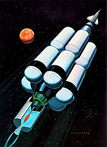
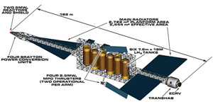
 This is from Use of High-Power Brayton Nuclear Electric Propulsion (NEP) for a 2033 Mars
Round-Trip Mission (2006). This is a study by the Revolutionary Aerospace Systems Concept (RASC) team, led by the NASA Langley Research Center.
This is from Use of High-Power Brayton Nuclear Electric Propulsion (NEP) for a 2033 Mars
Round-Trip Mission (2006). This is a study by the Revolutionary Aerospace Systems Concept (RASC) team, led by the NASA Langley Research Center.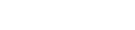


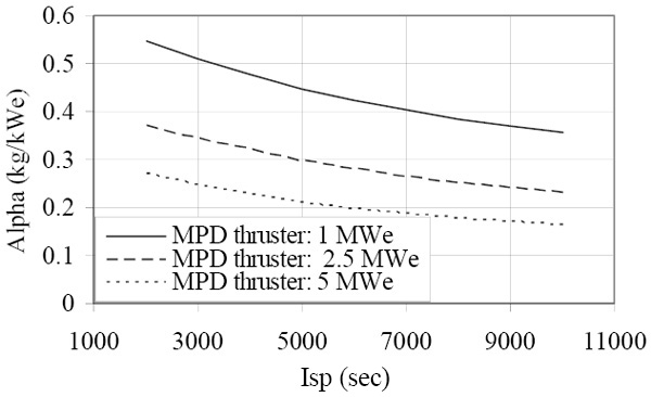
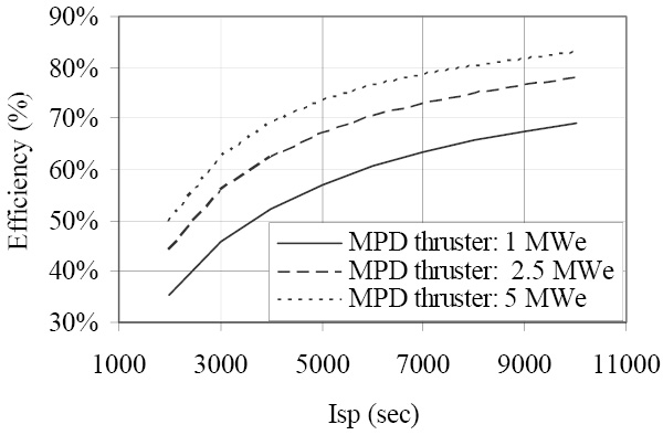

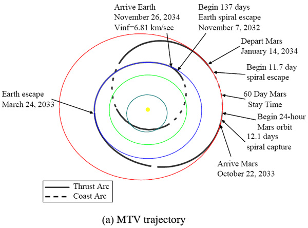
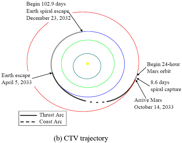
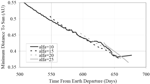


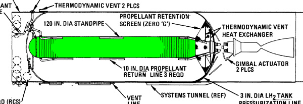

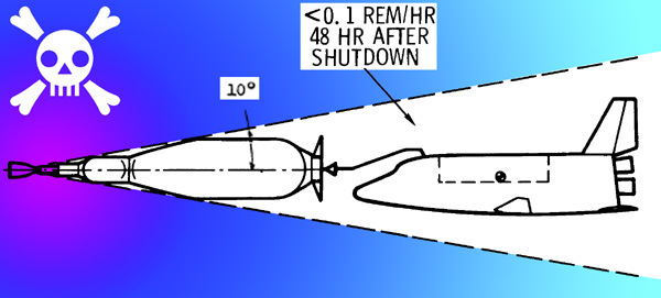
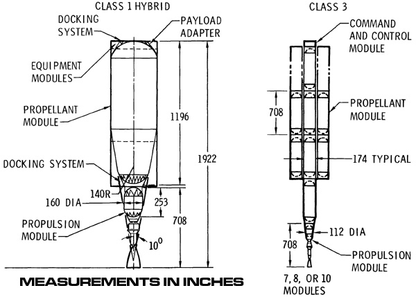
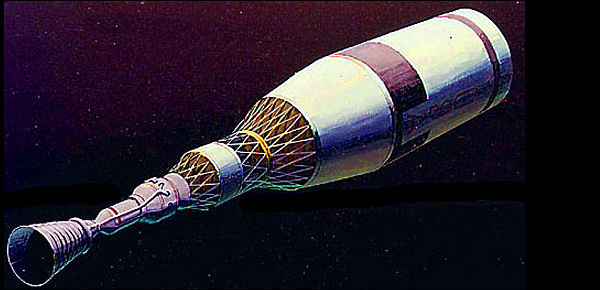
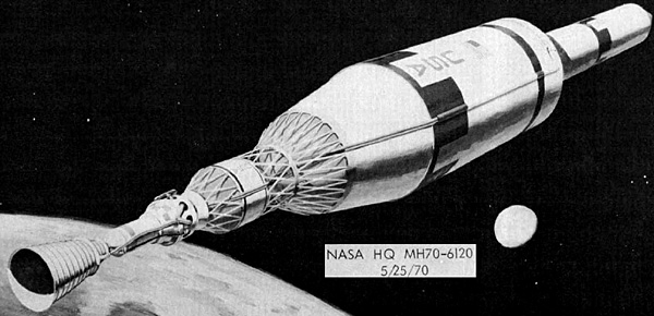
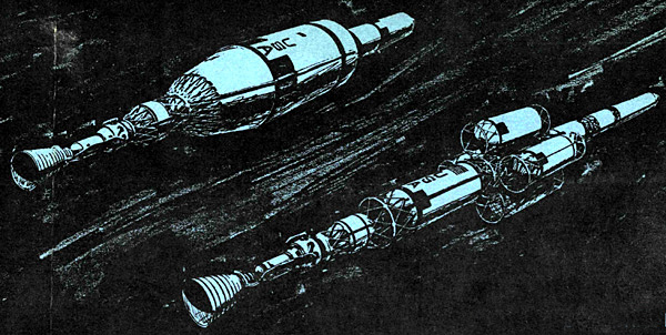


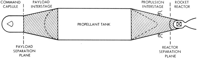
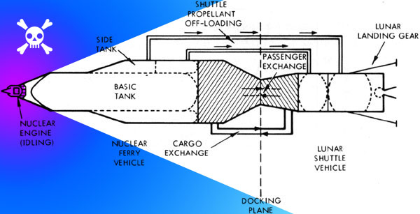
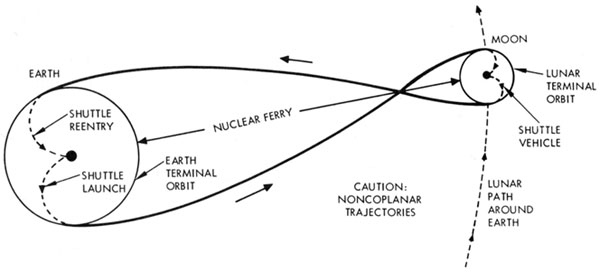


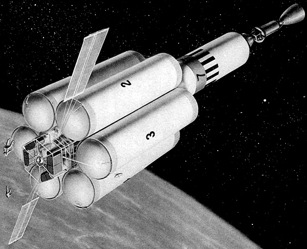
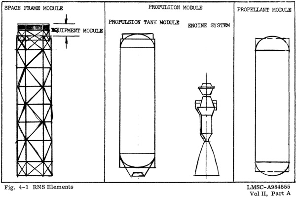
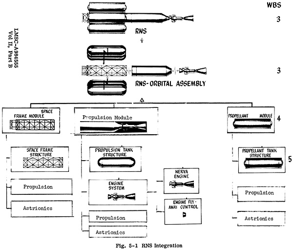
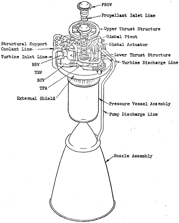


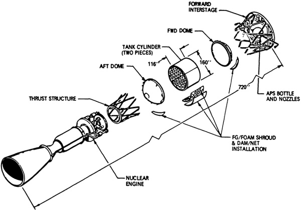

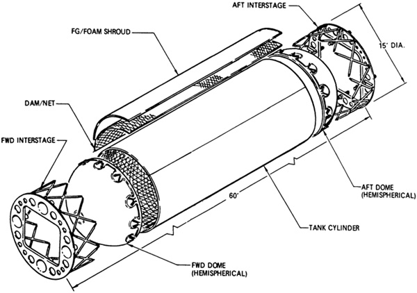


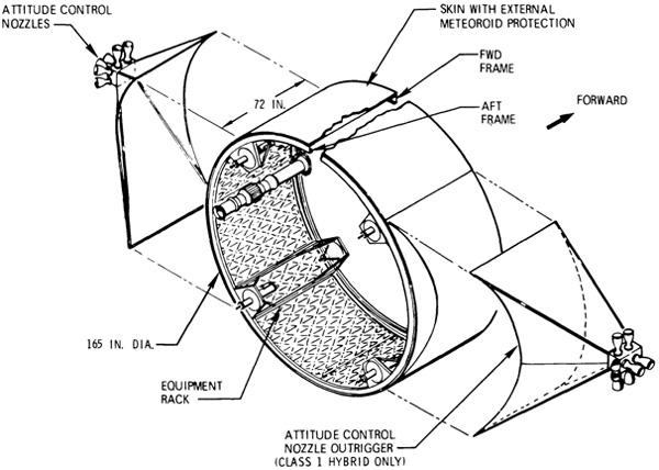


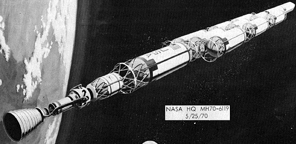
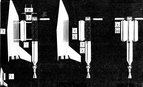
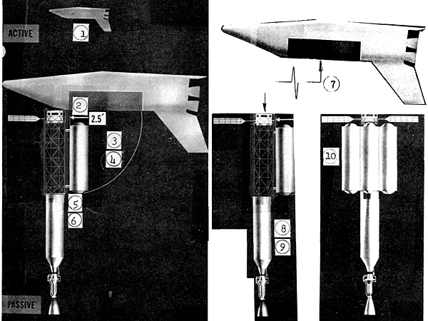
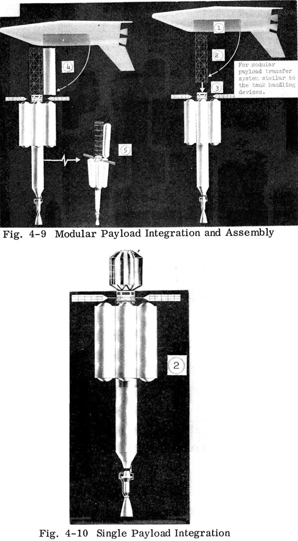


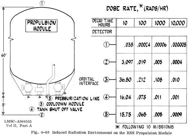
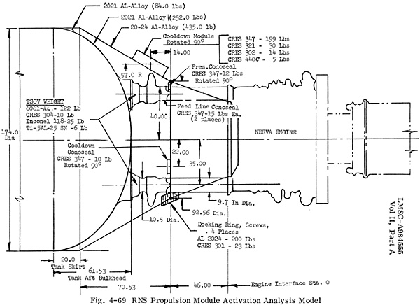
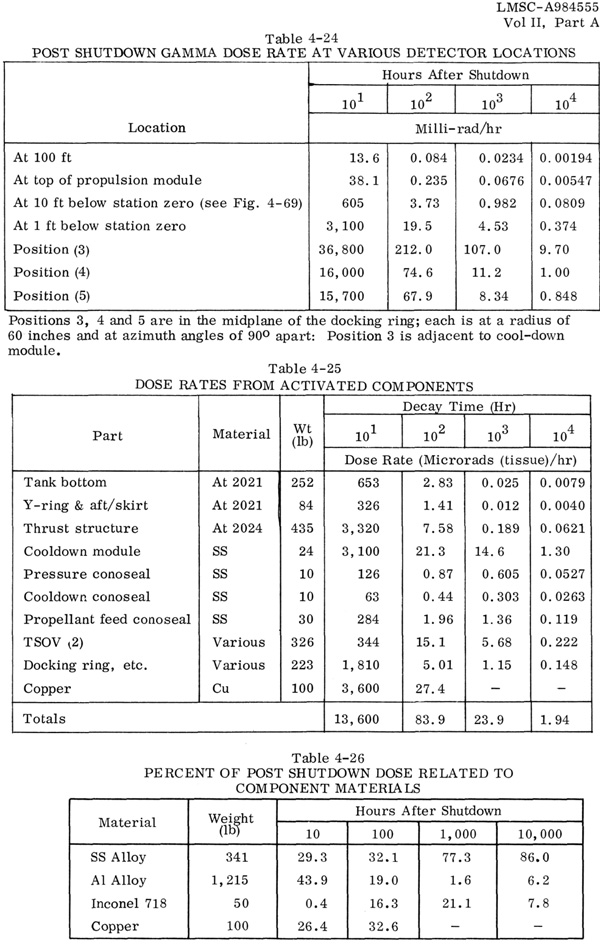

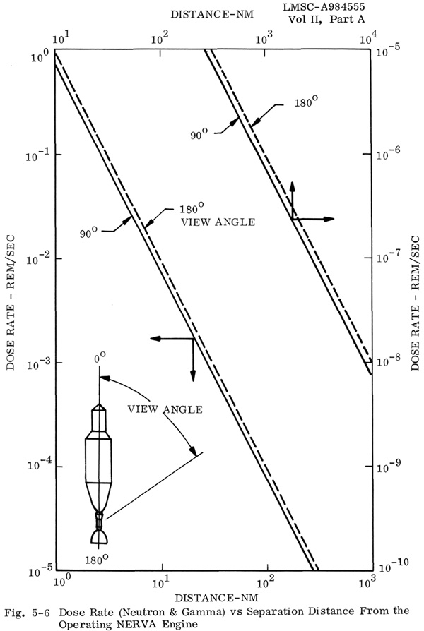

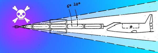

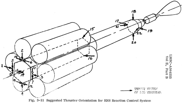
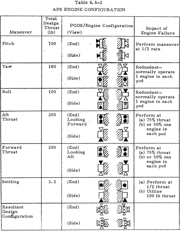
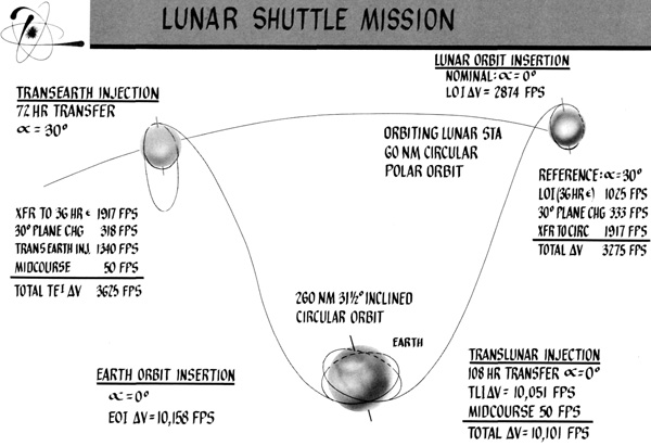
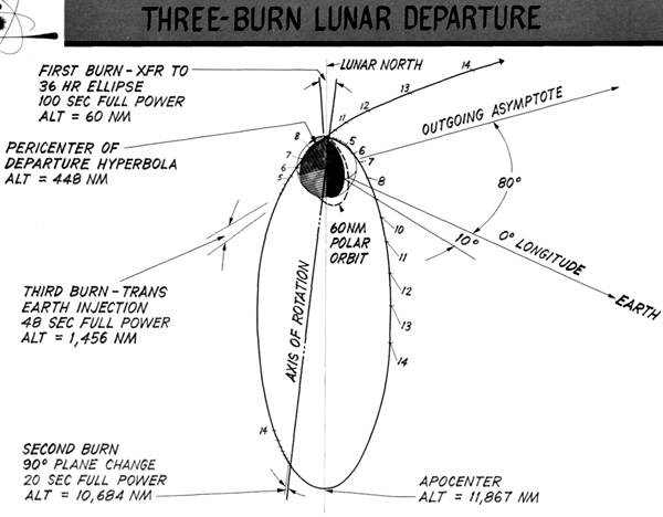


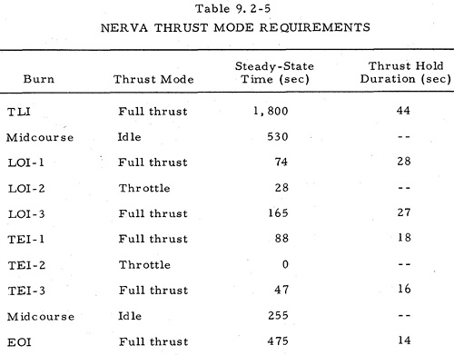
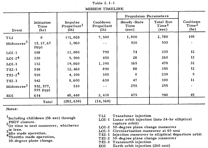
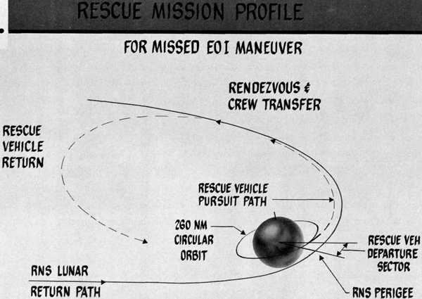
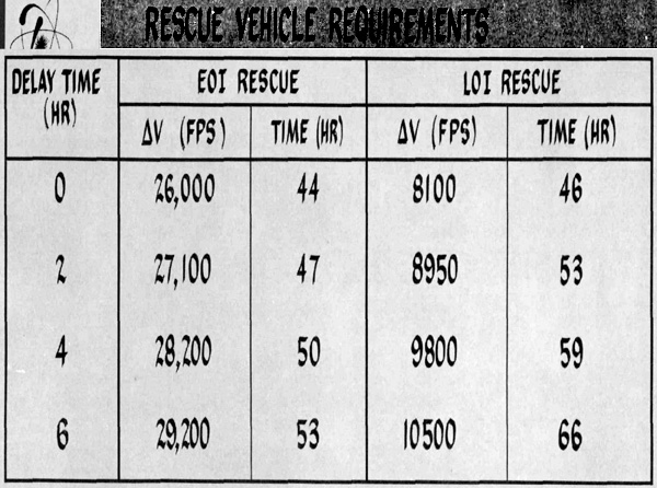
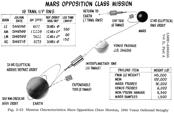
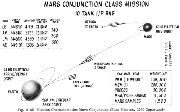
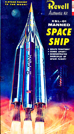
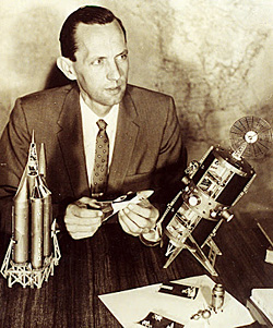
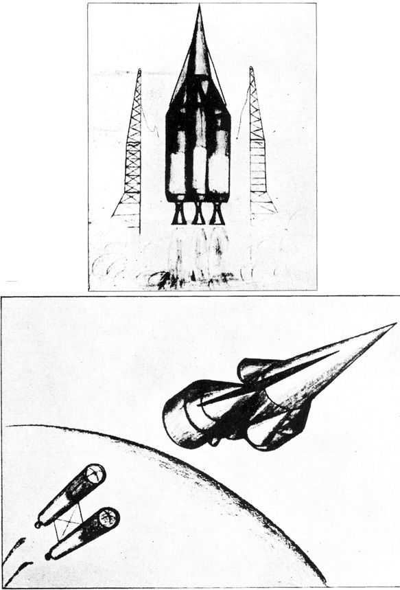

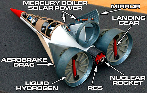

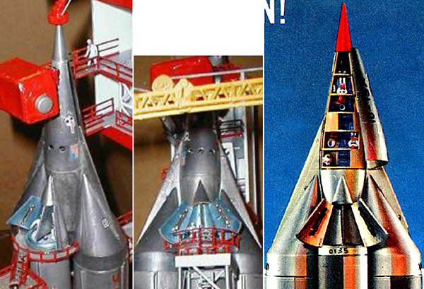


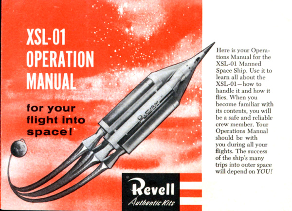
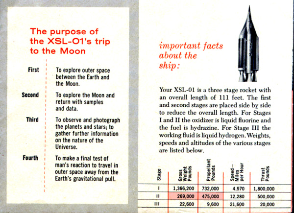
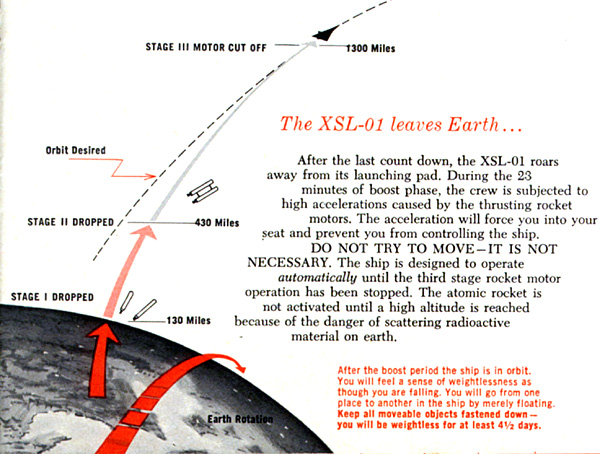
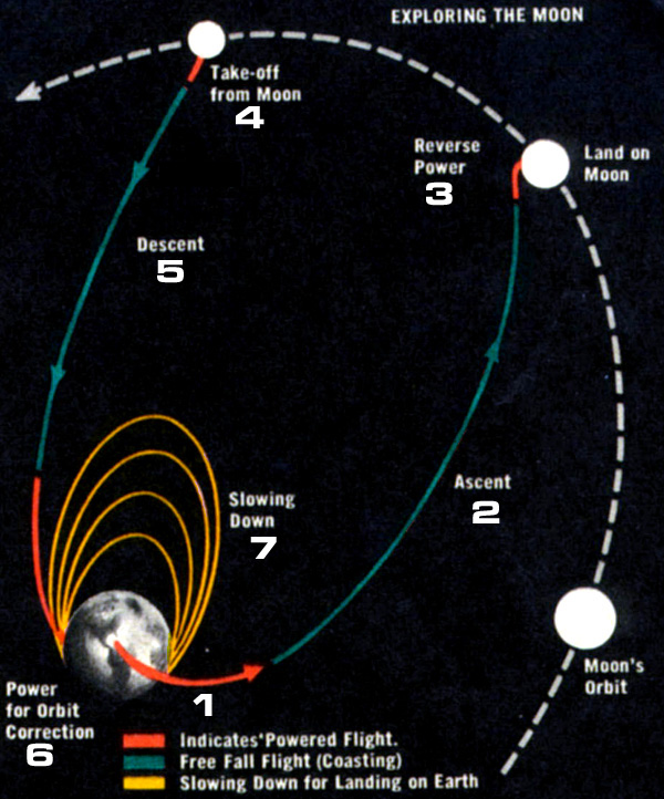
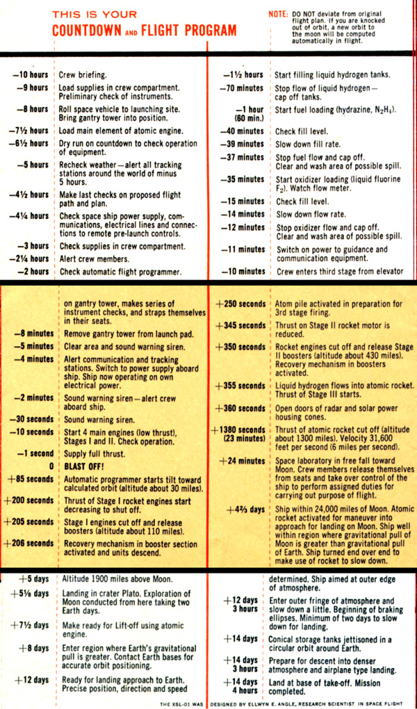


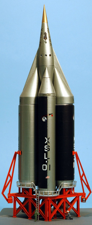
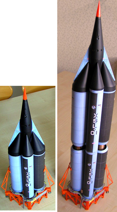
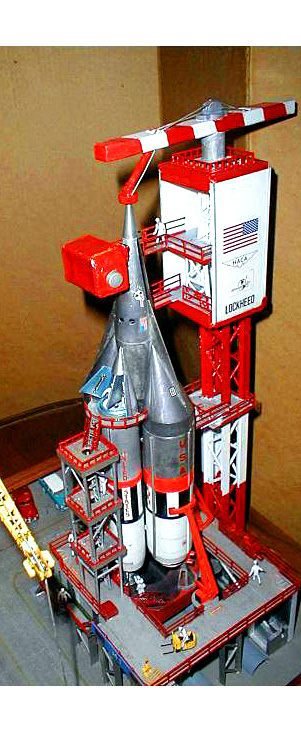
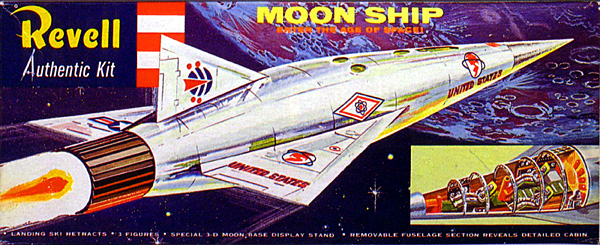
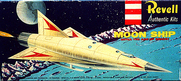
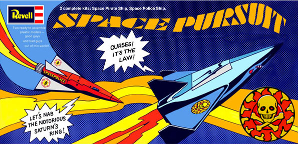
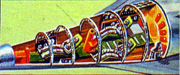
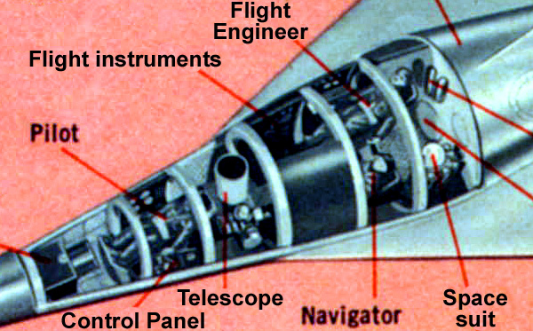


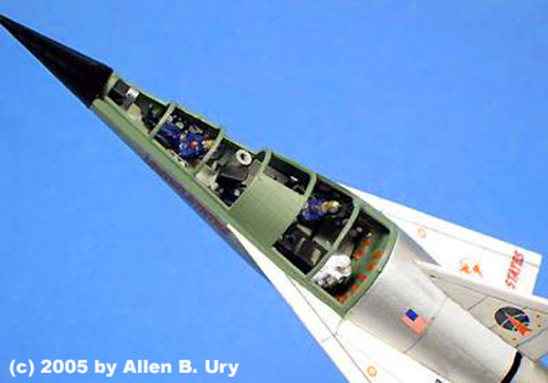
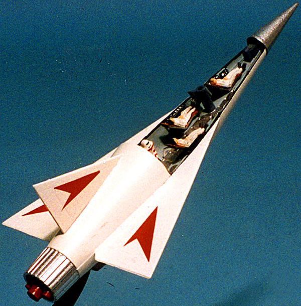
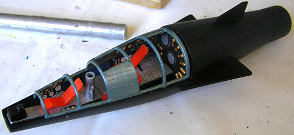
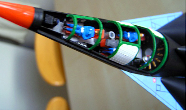
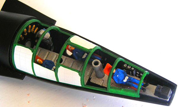
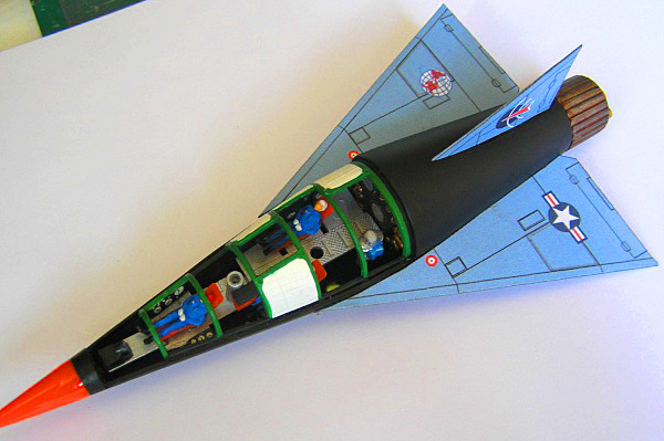
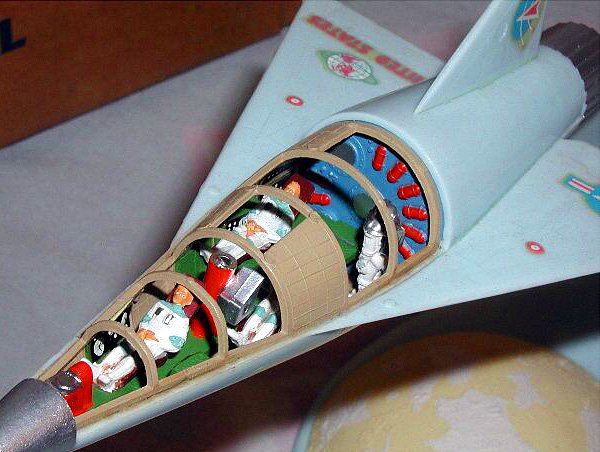
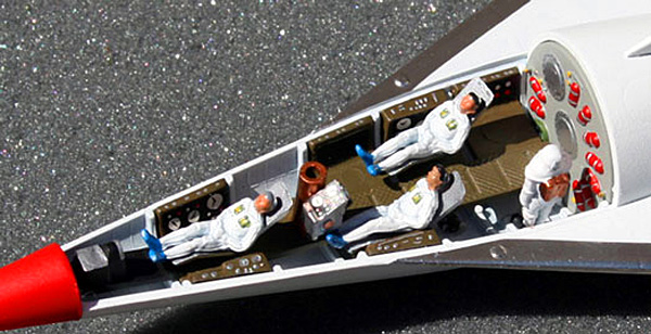
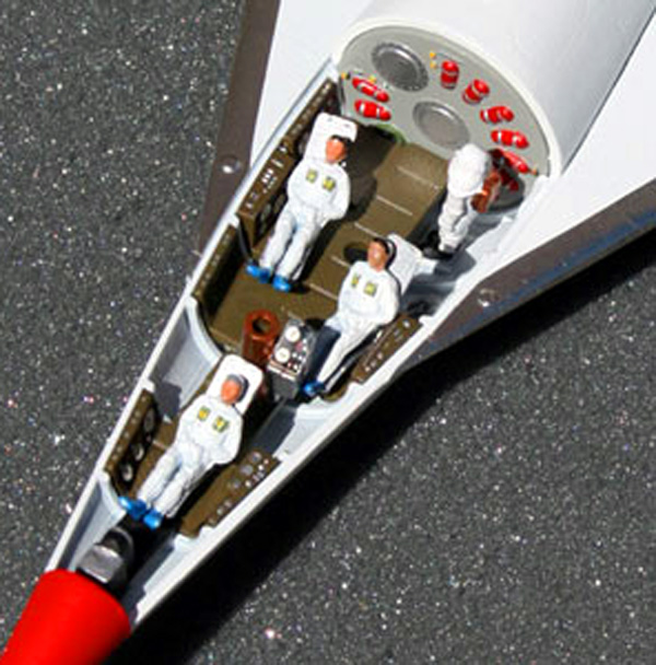


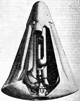
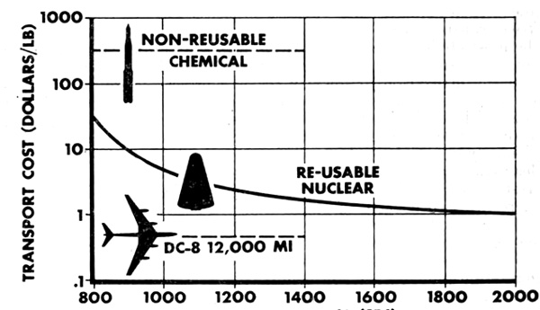
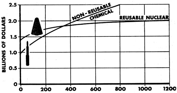
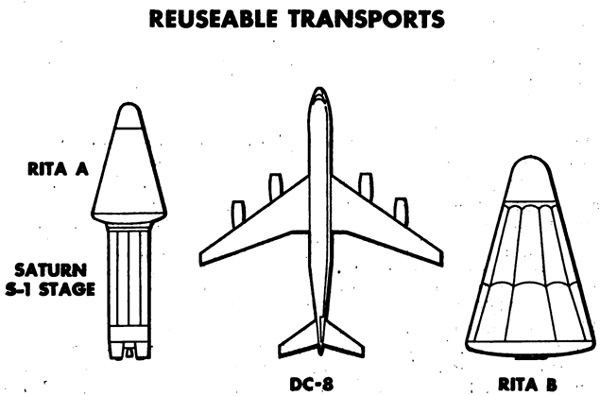
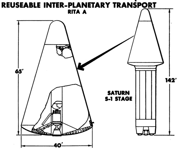
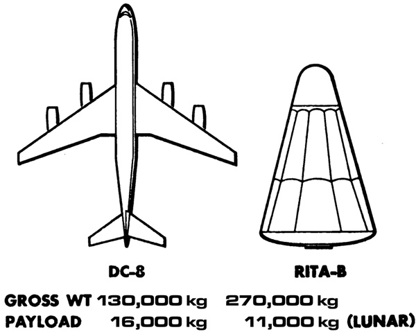
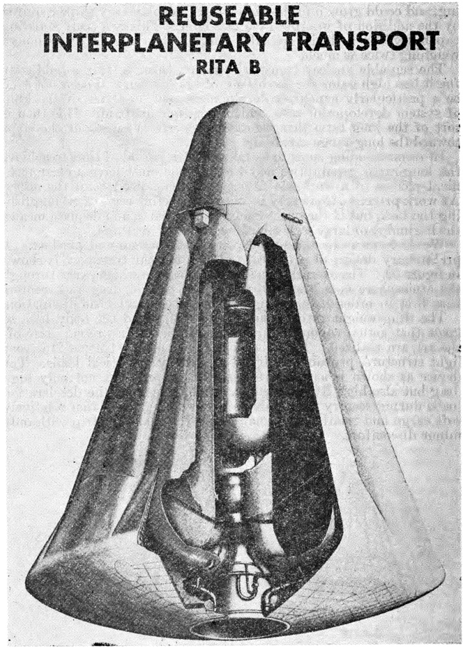
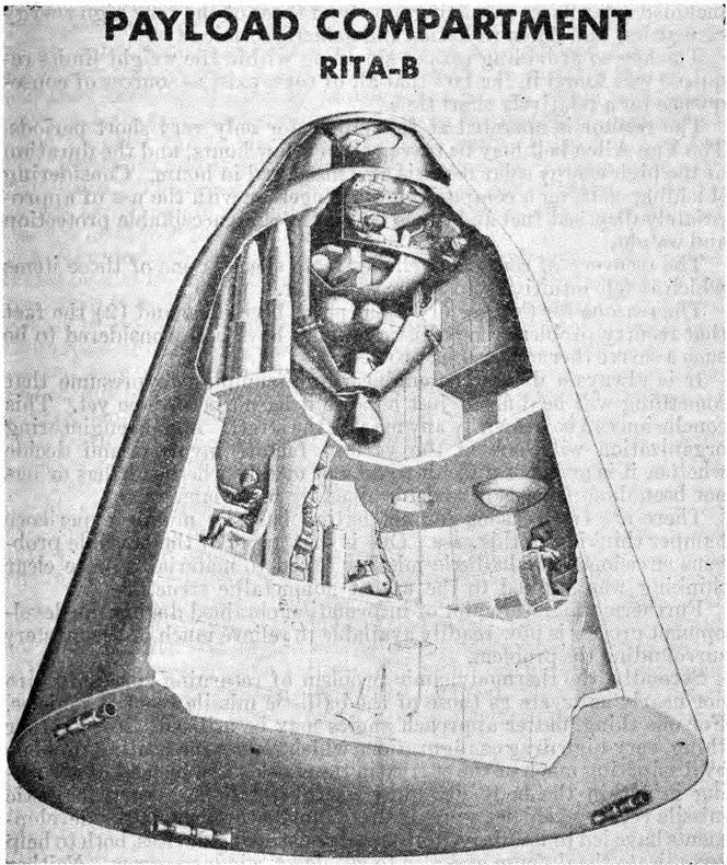
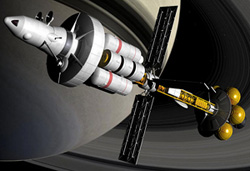


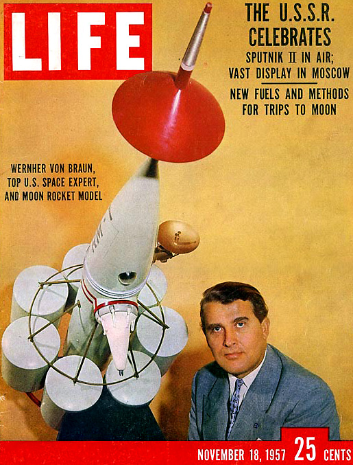


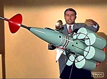
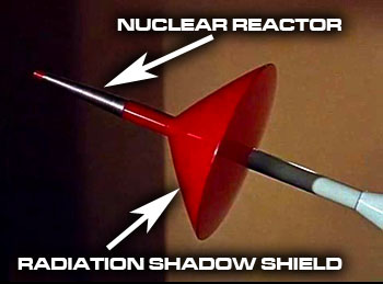
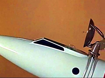
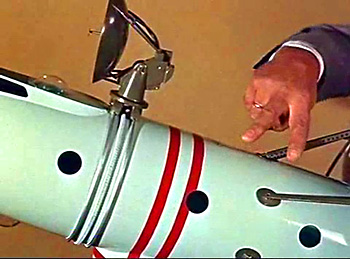
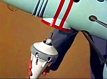
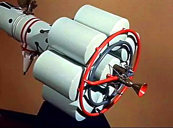
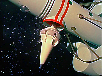
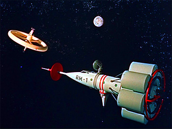
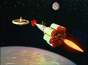
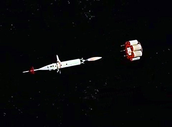
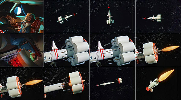
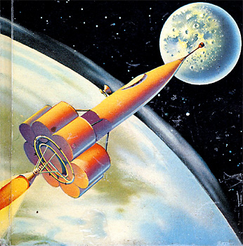
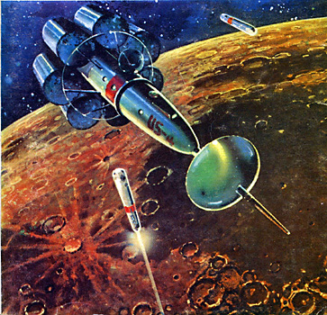


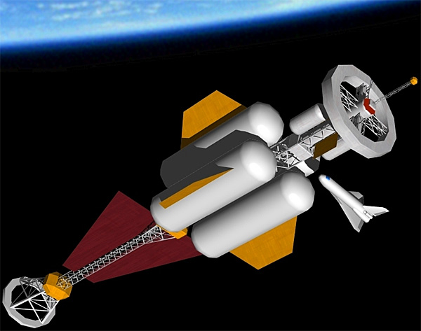


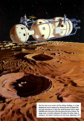
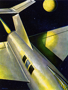

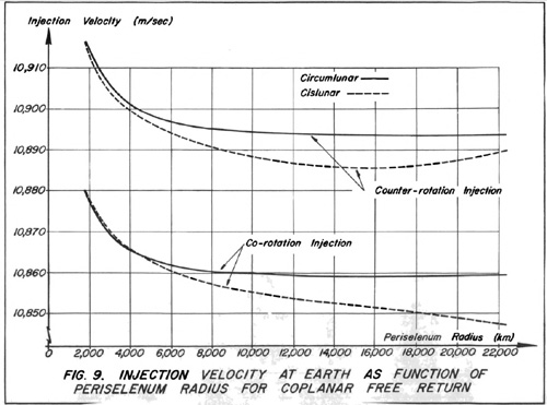
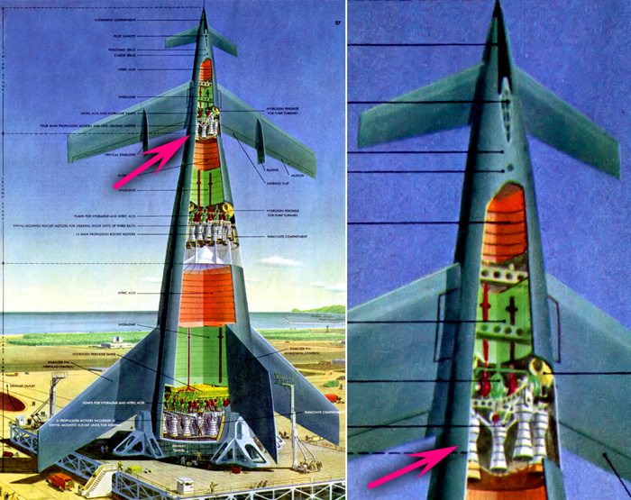

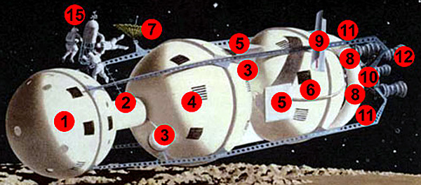

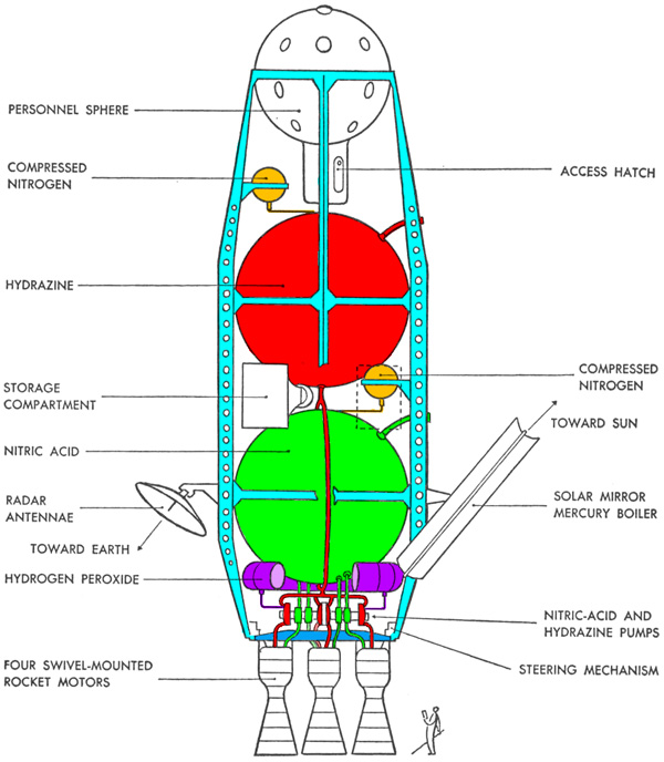
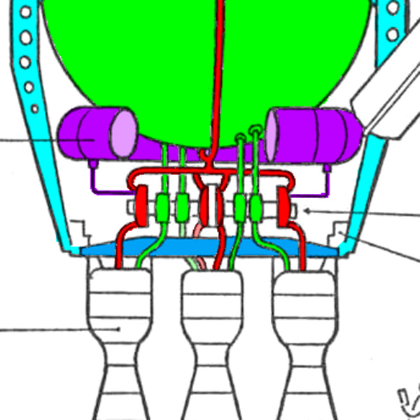
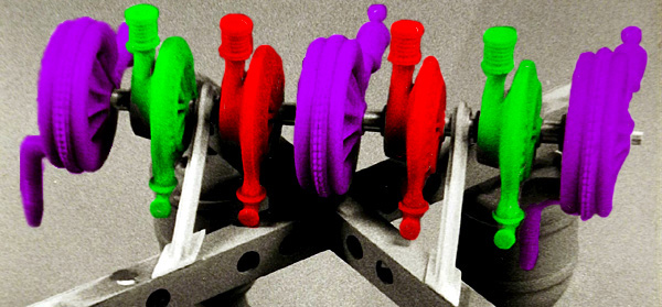
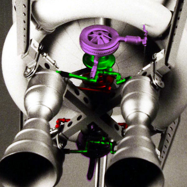


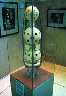
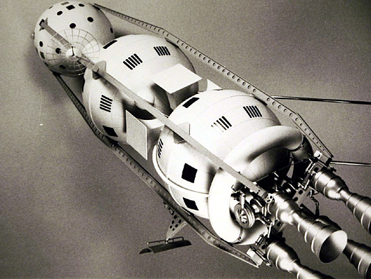
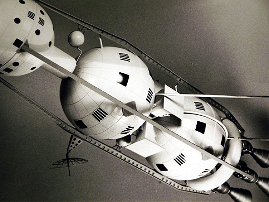
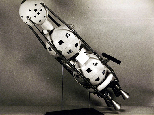
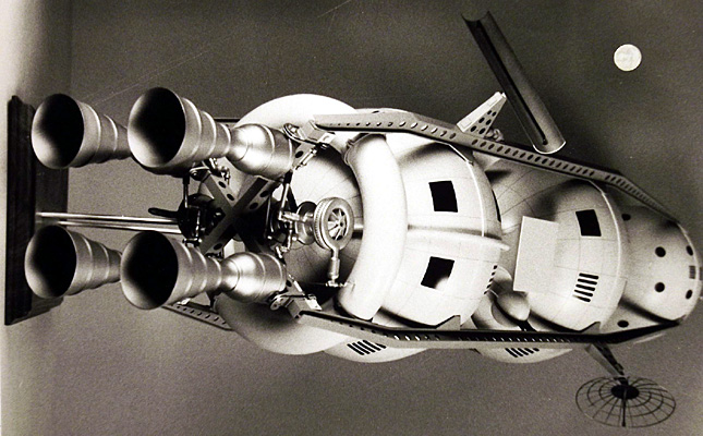
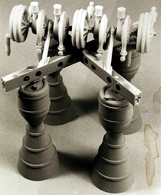
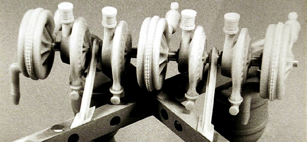
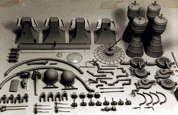
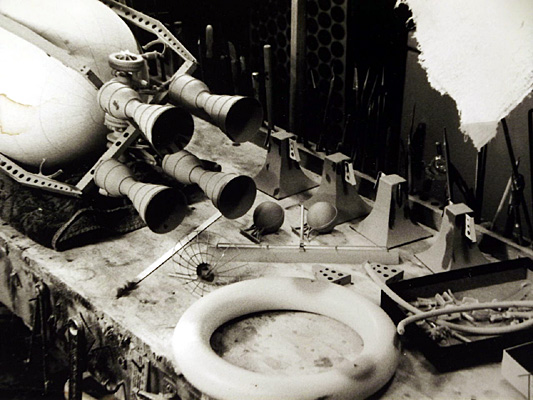
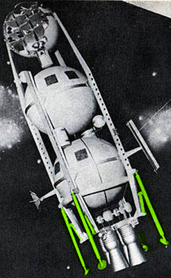
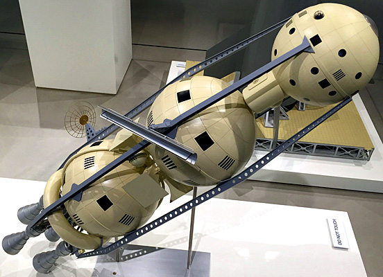


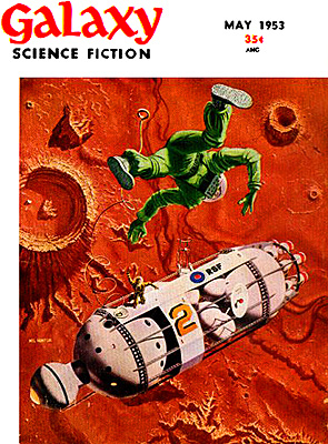
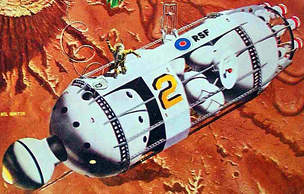
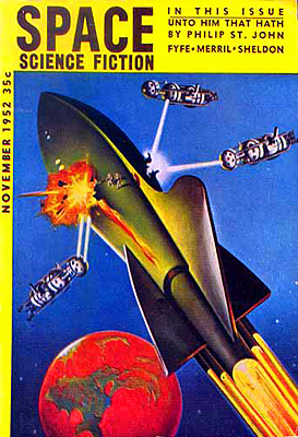

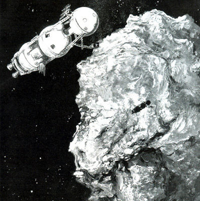

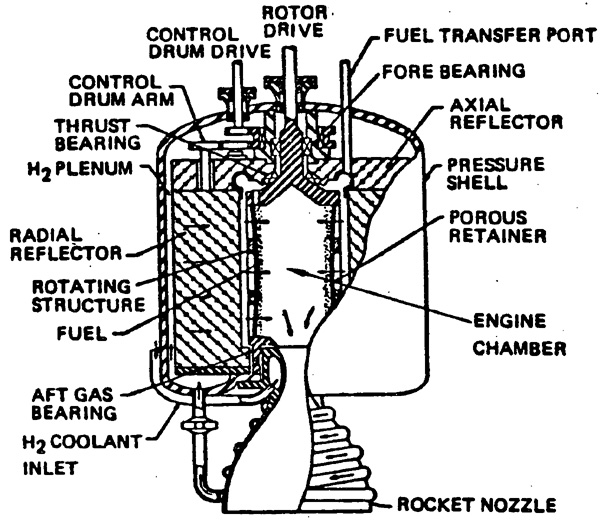
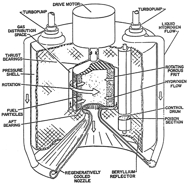
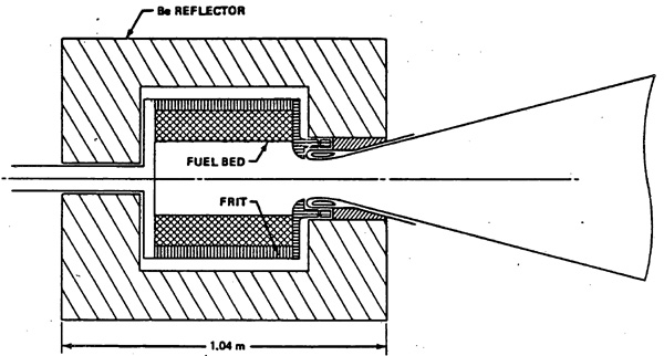
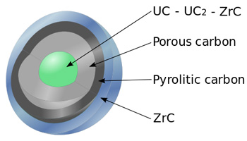

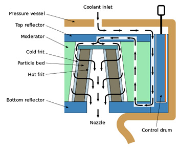
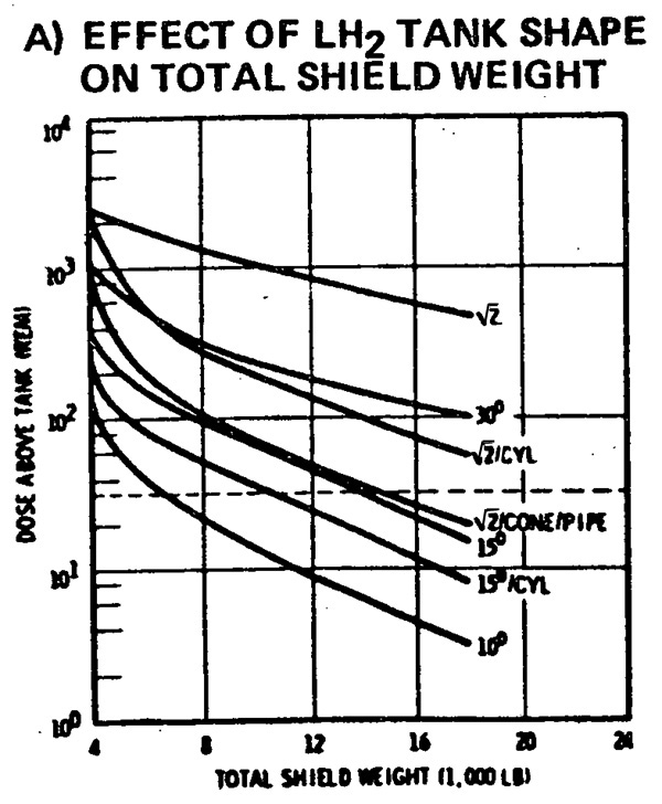
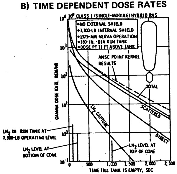


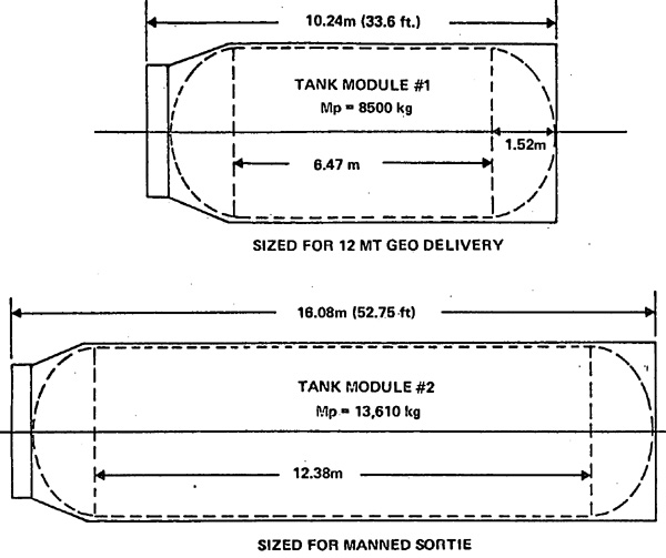
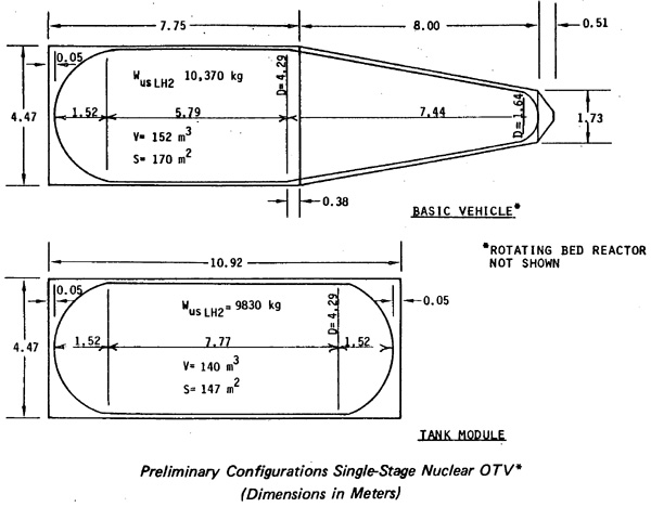
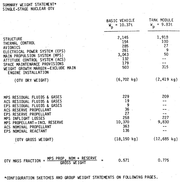
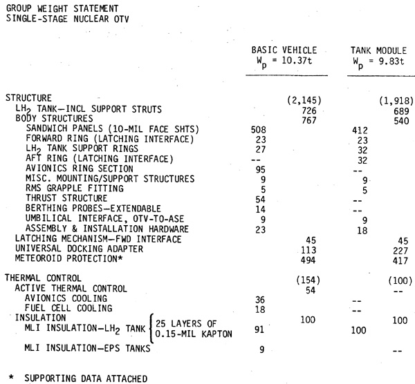
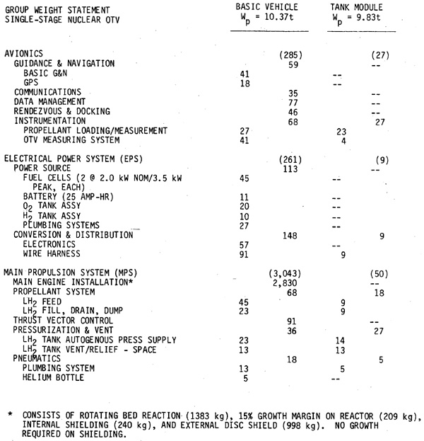
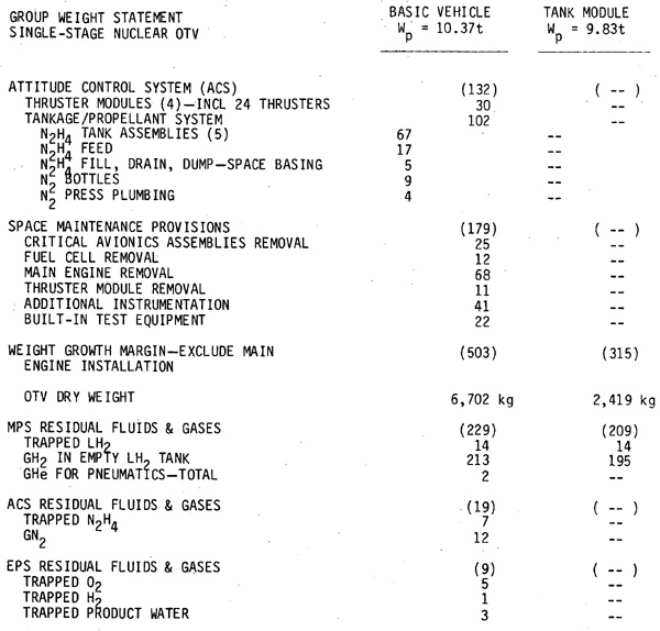
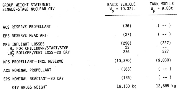


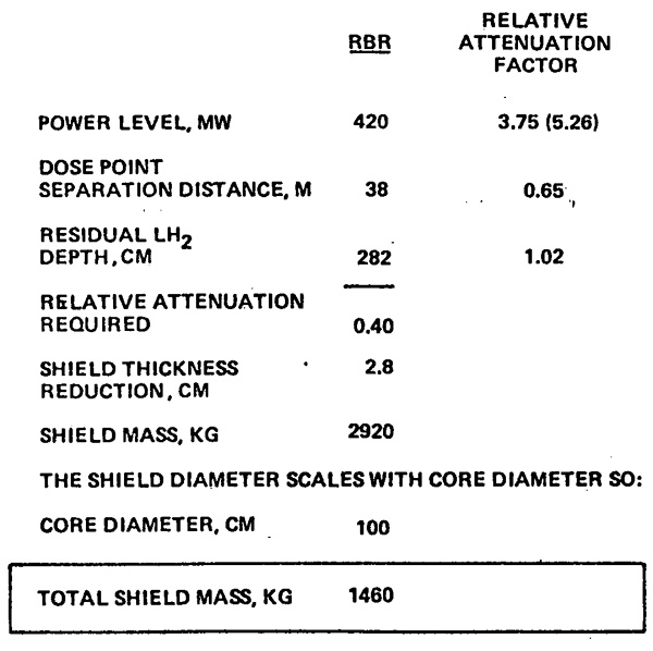
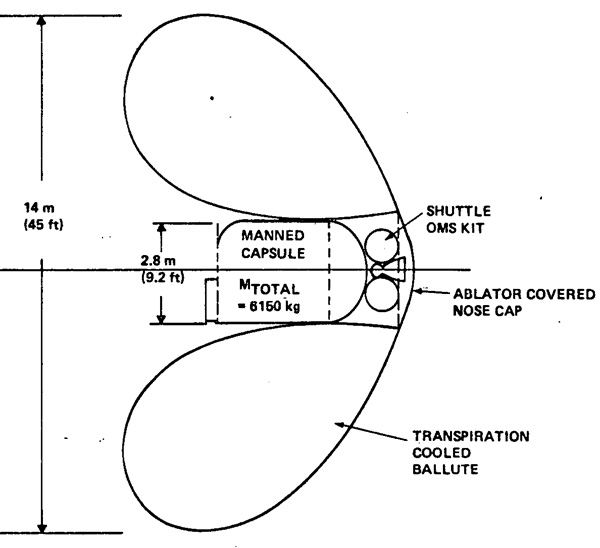
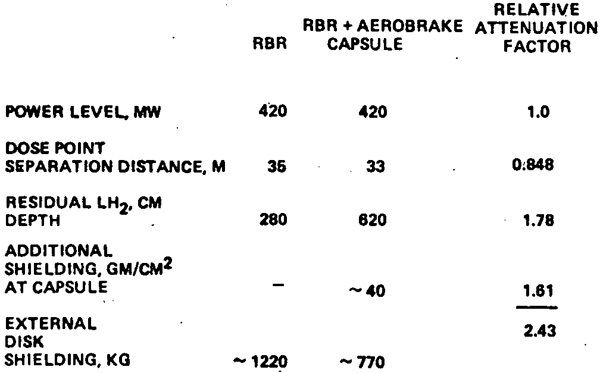


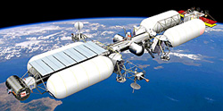
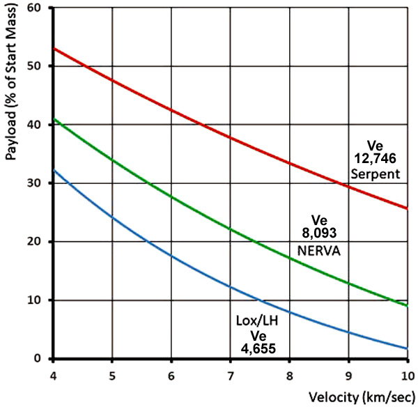

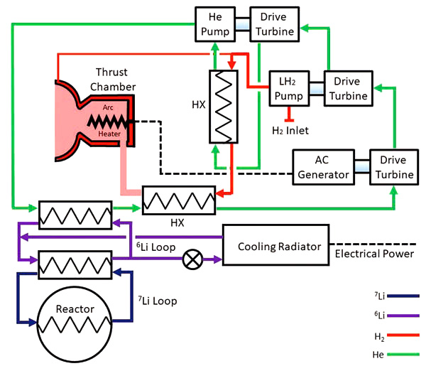


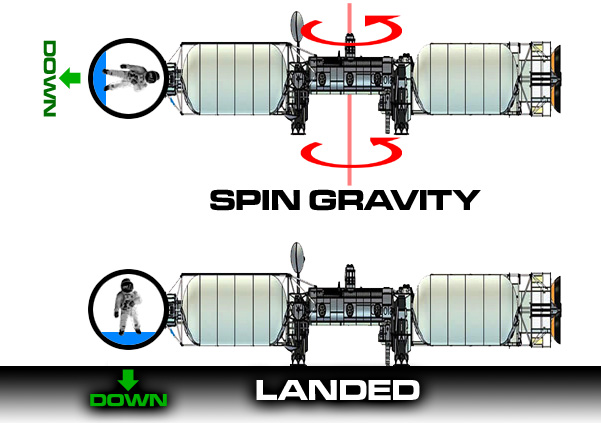
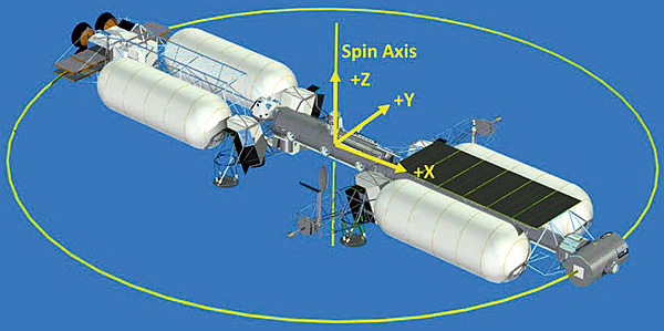
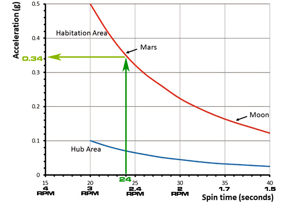
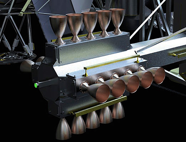
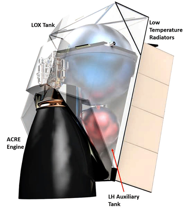
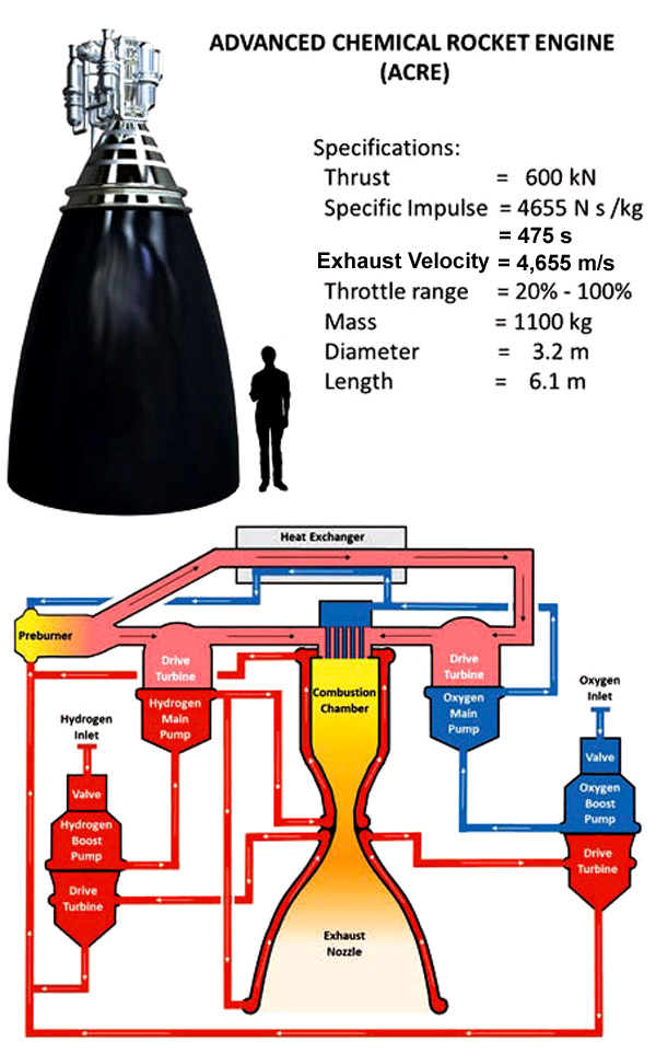
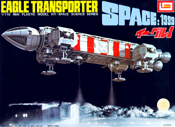
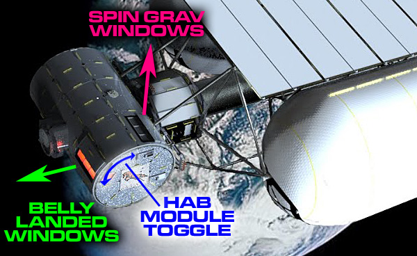


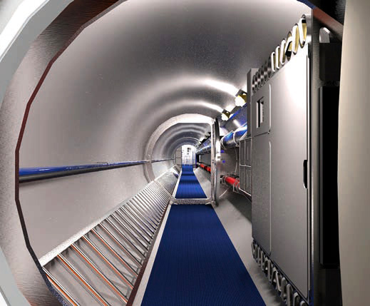
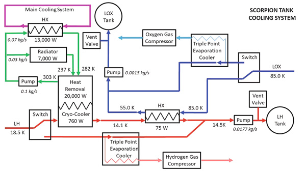
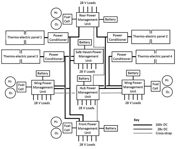

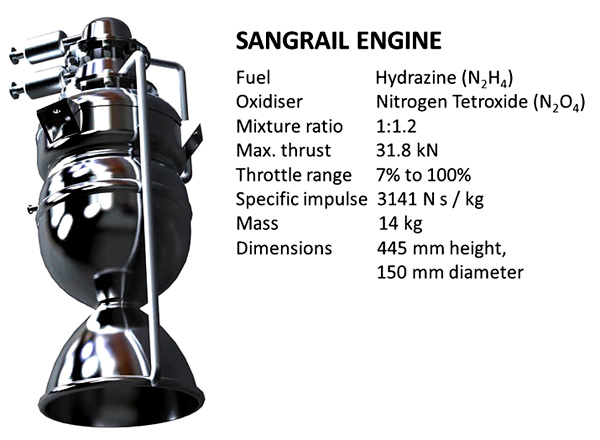


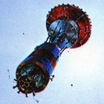
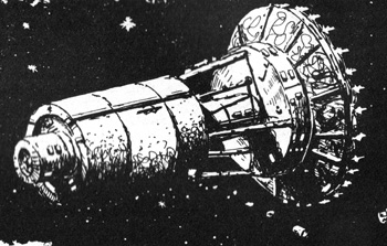


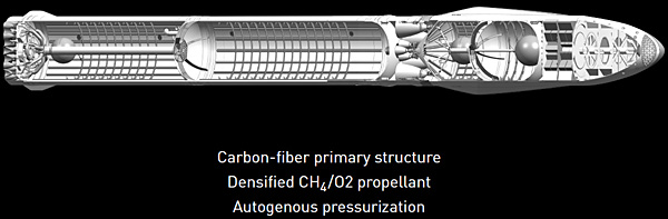
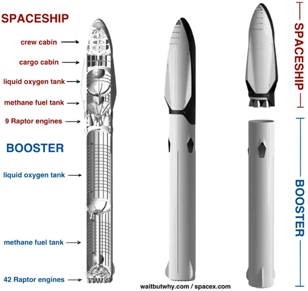
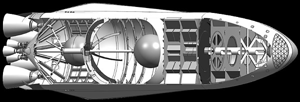
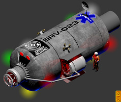
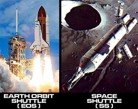
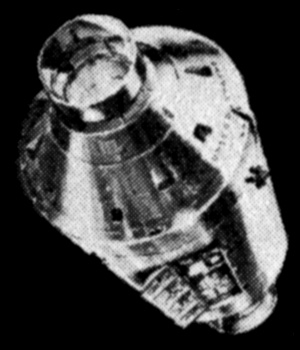
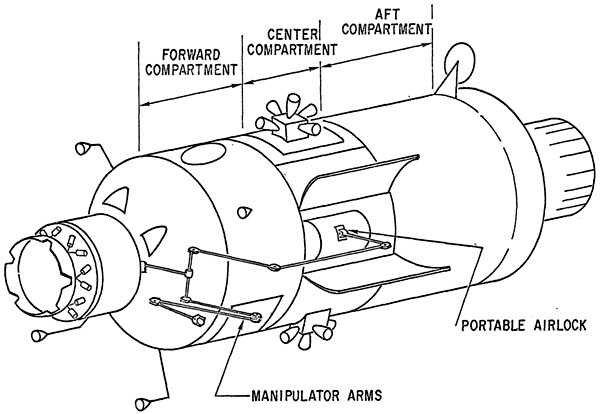


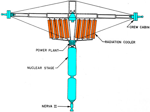
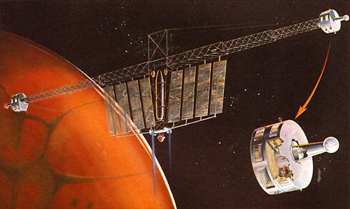
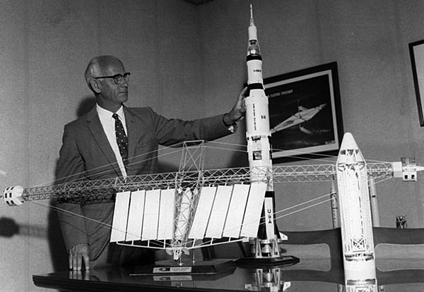


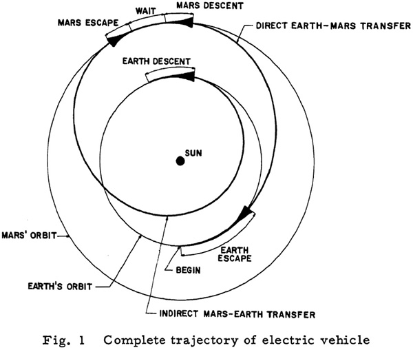
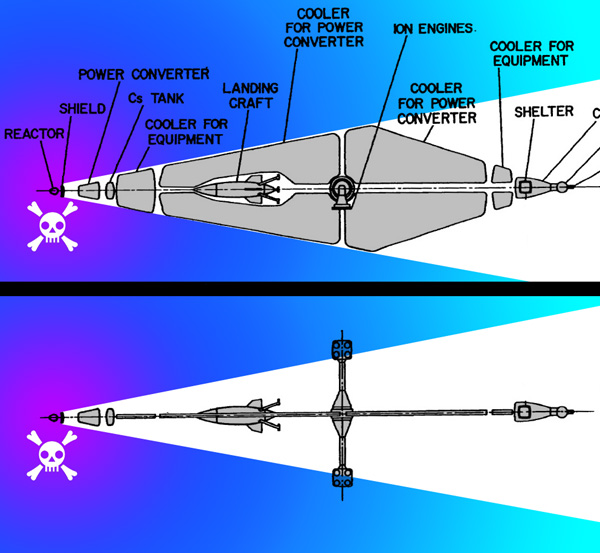
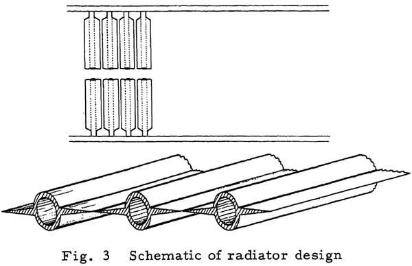
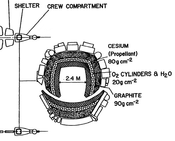


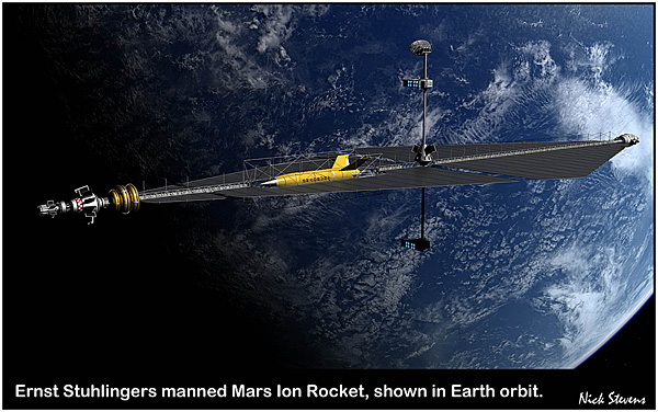
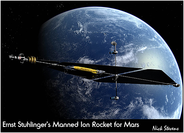
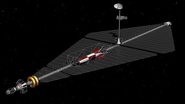
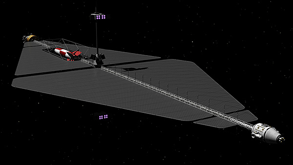
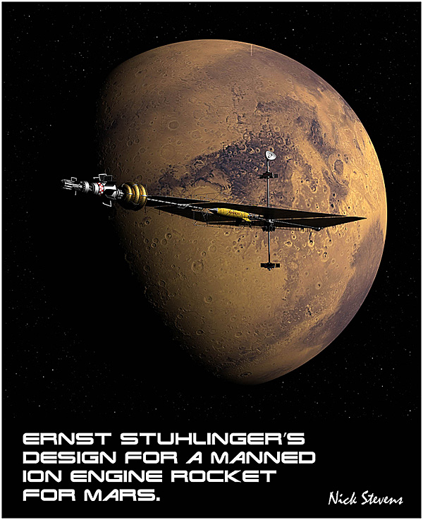


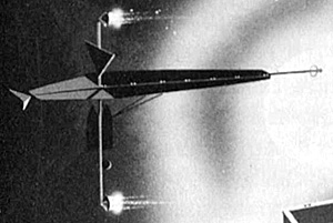
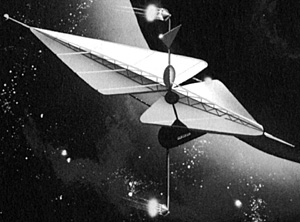


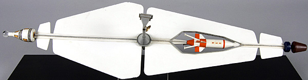
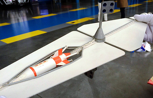
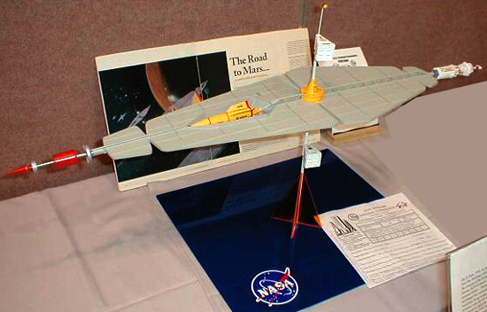


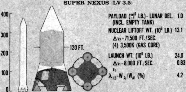
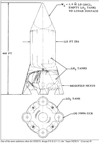


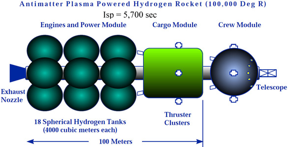
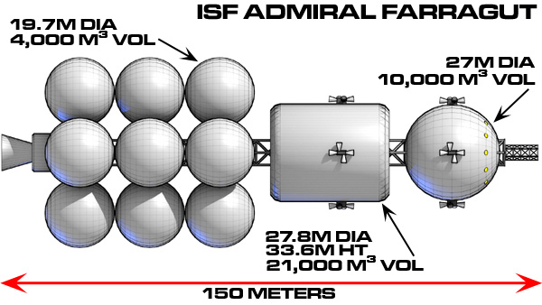
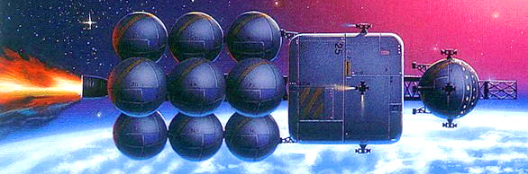
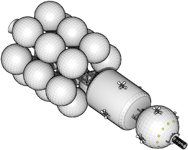
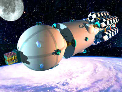
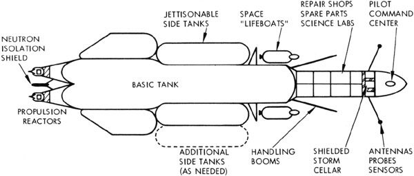

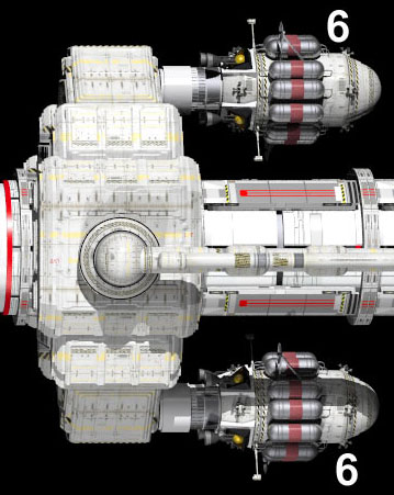
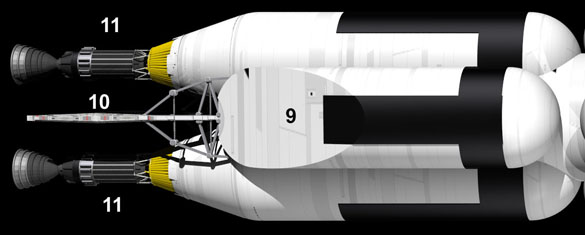

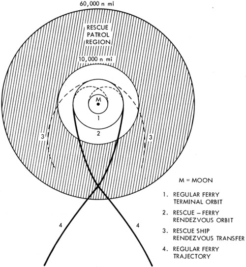
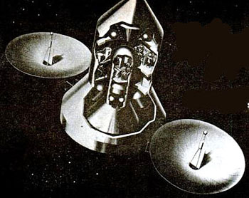
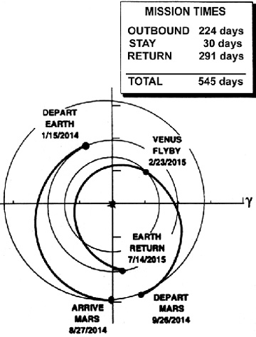
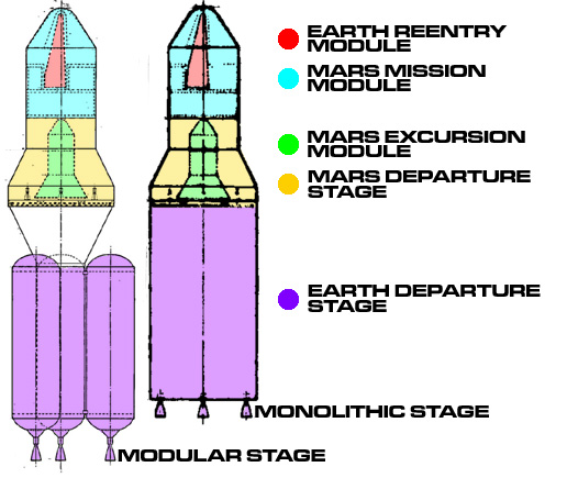
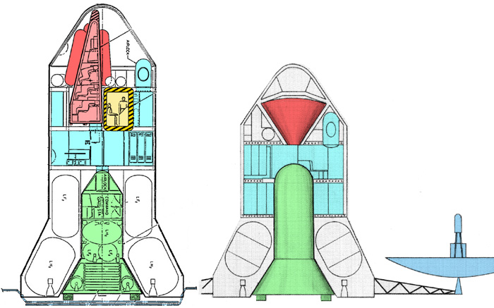
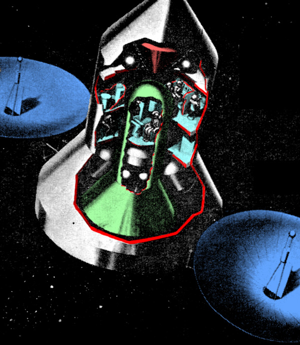
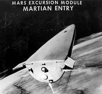
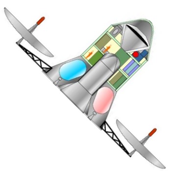
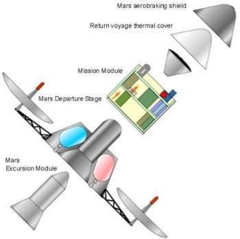

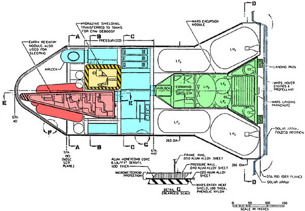
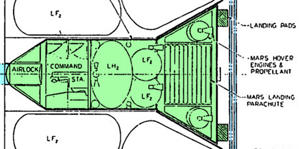
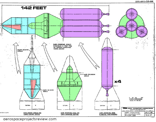
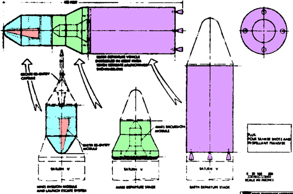


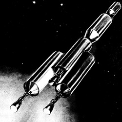

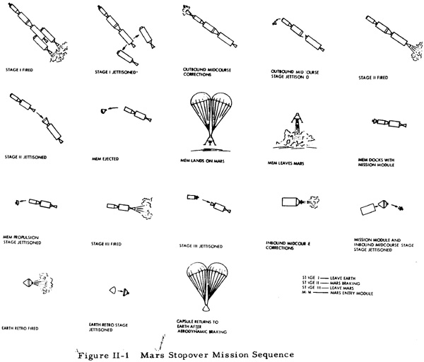
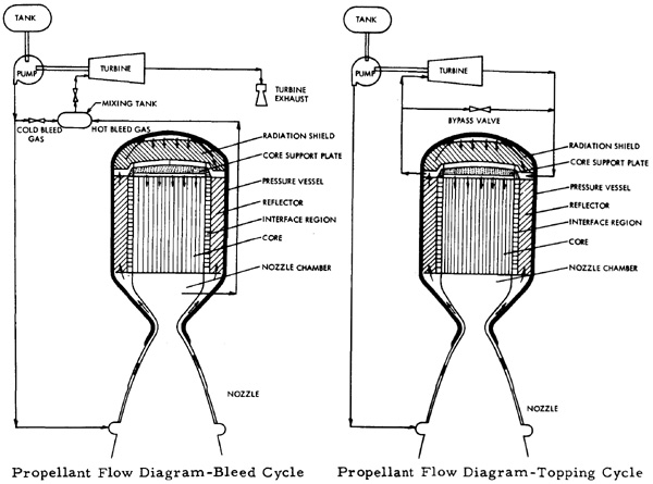

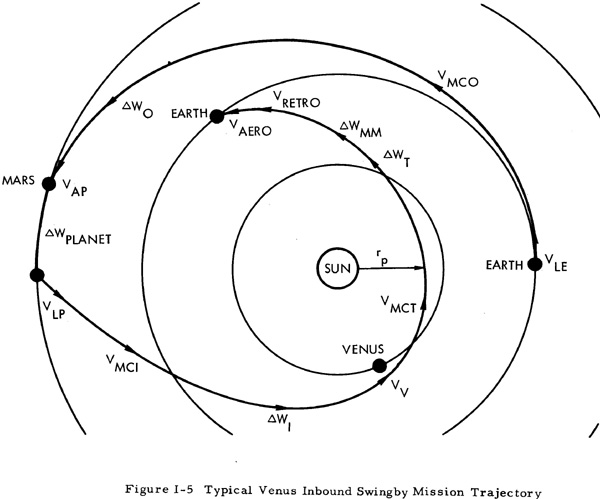
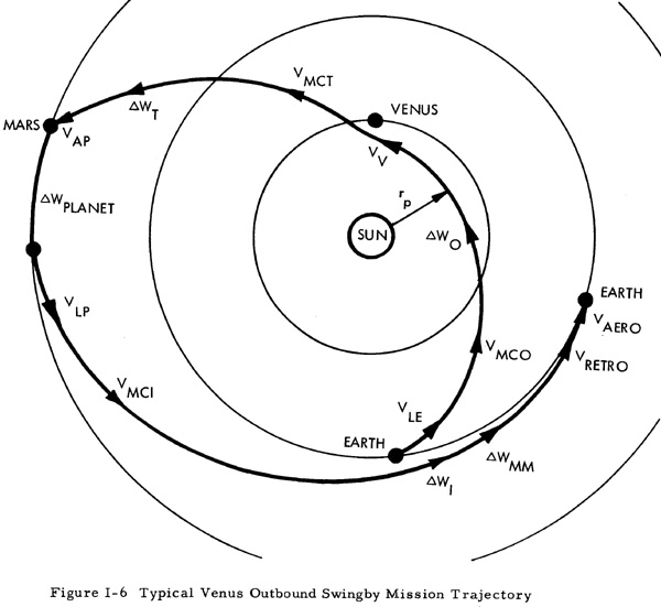
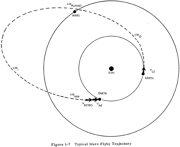


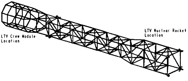
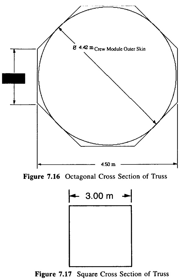
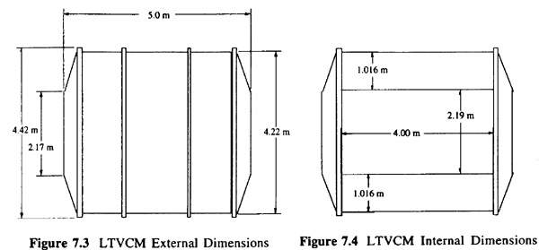
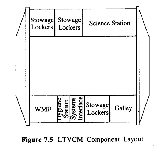

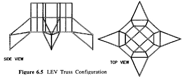
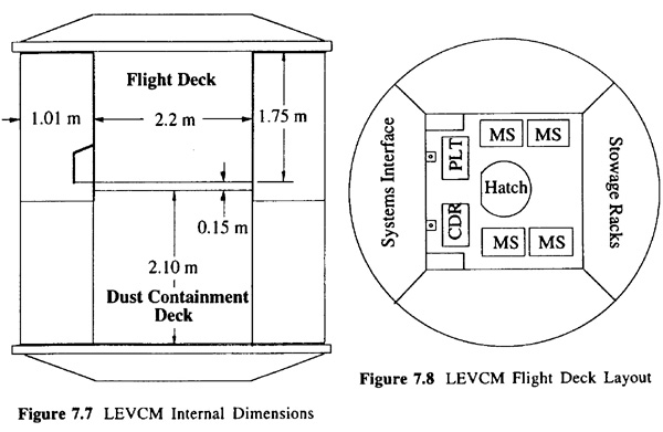
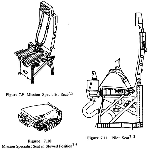


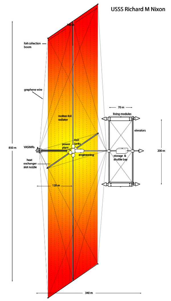

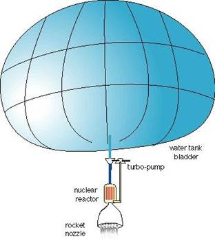

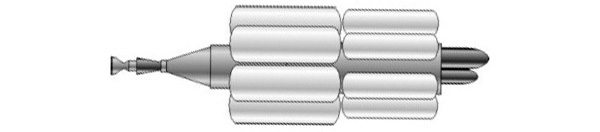
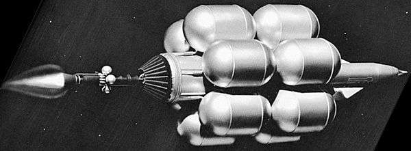
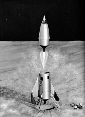
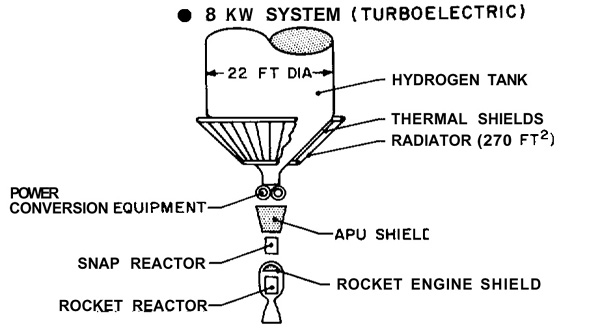
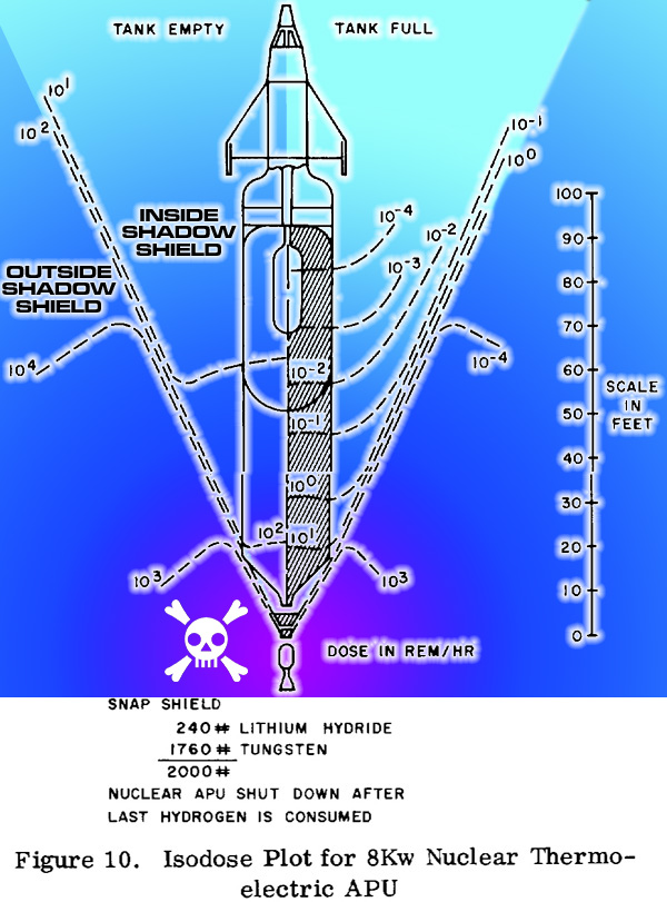

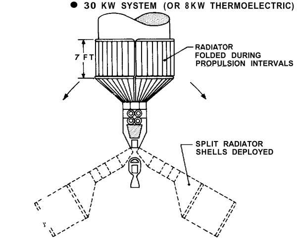

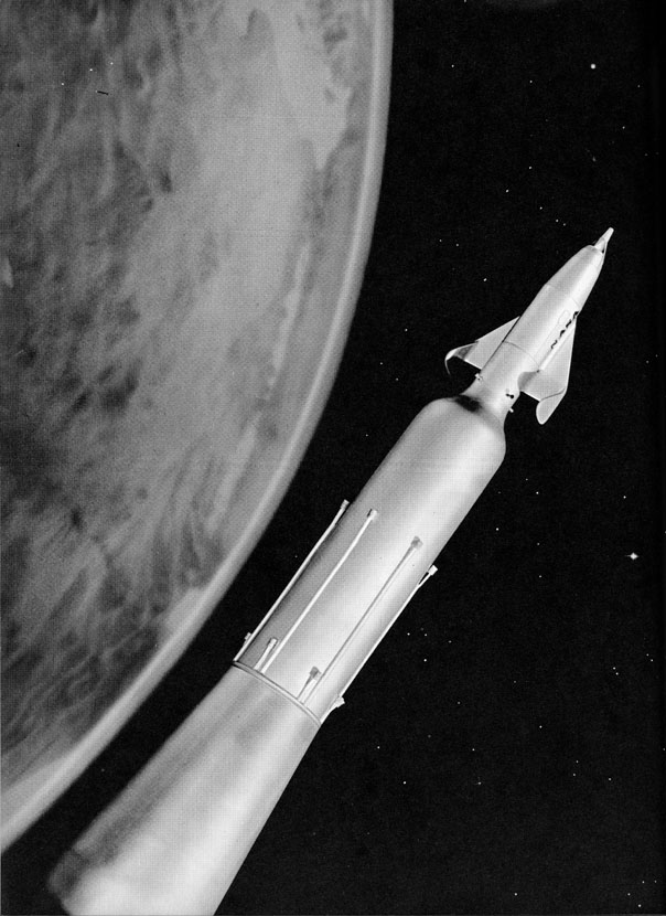
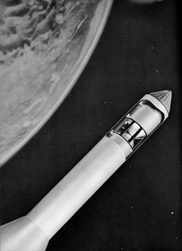
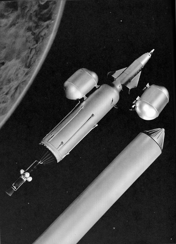
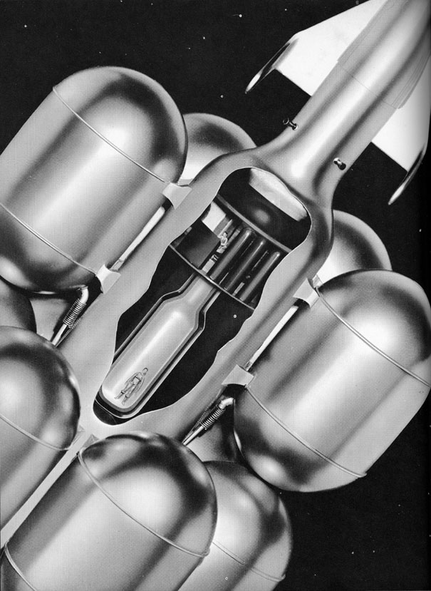
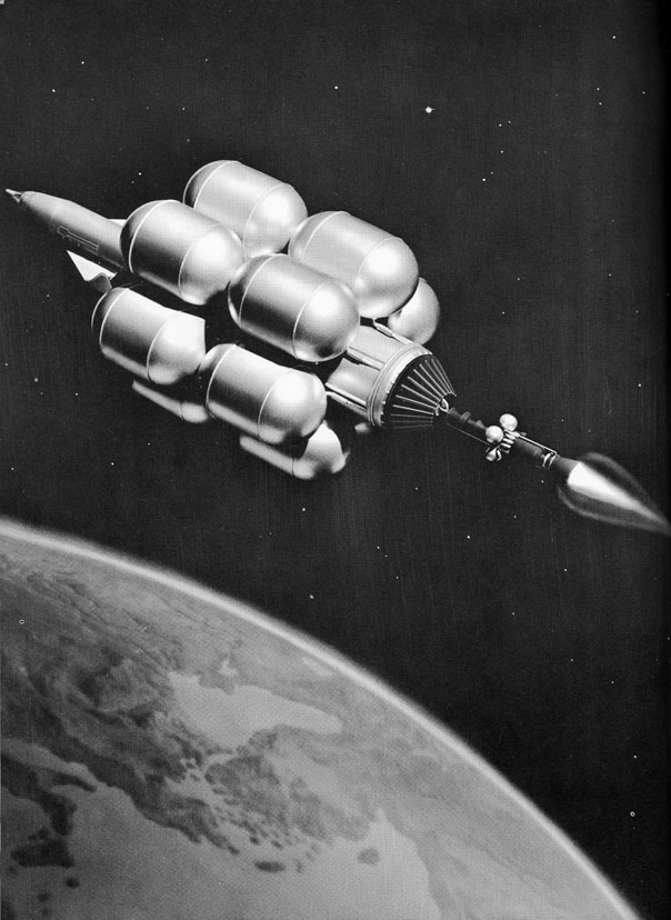
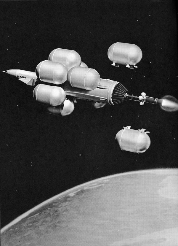
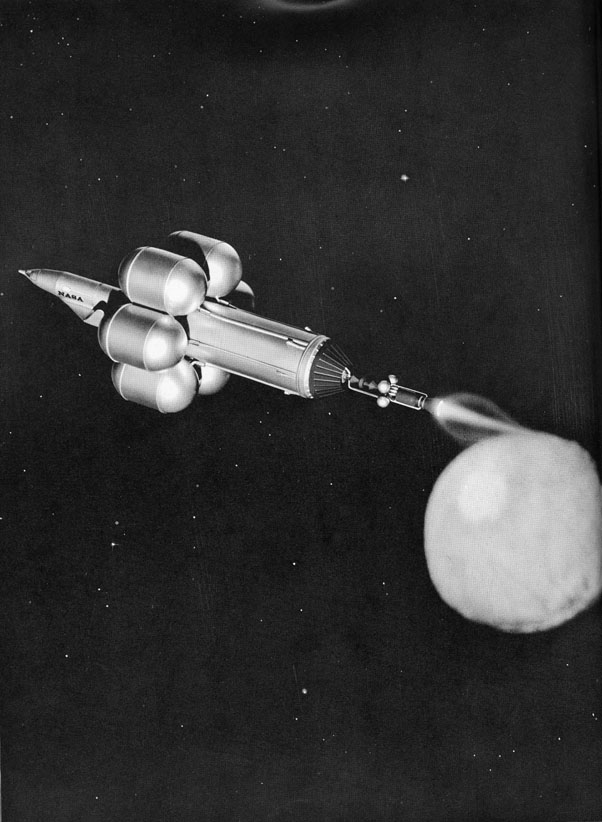
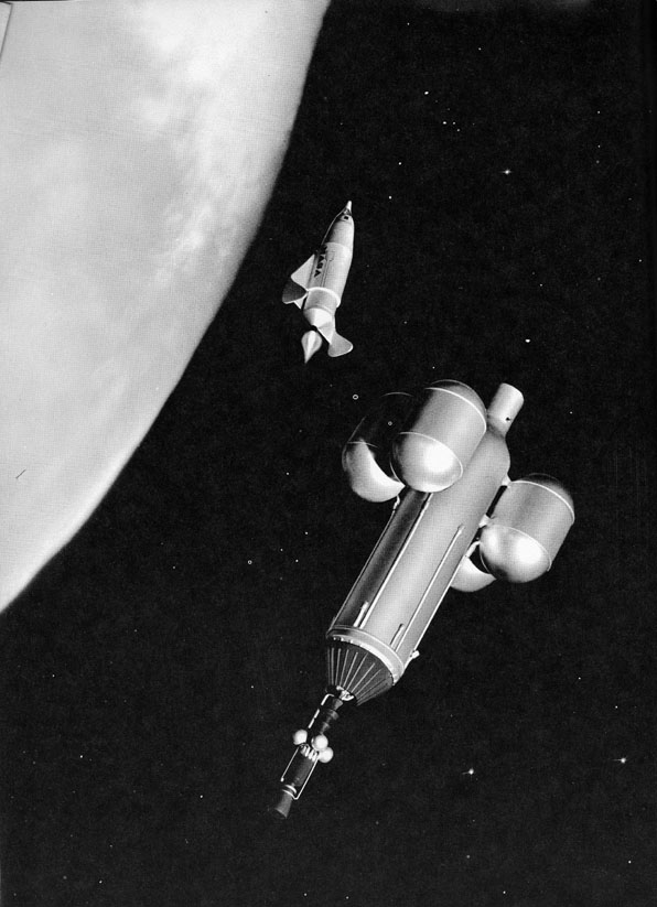
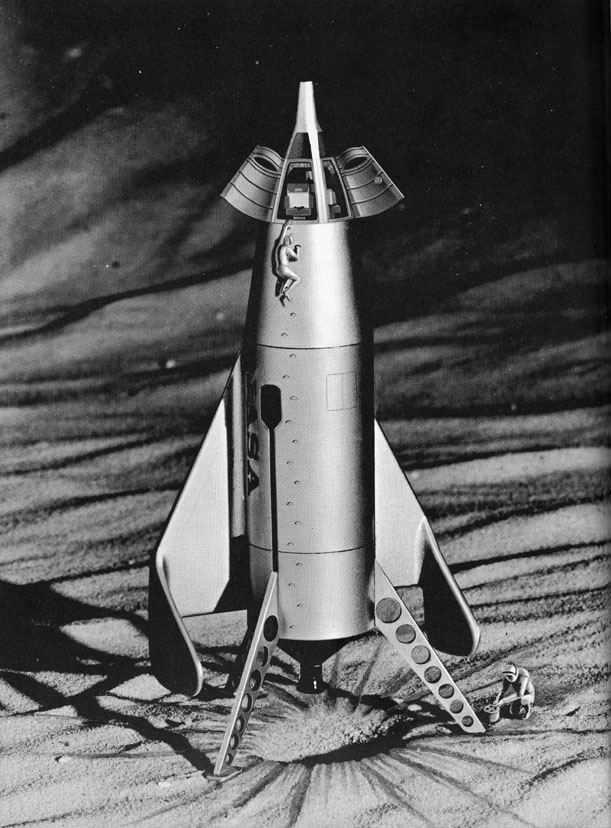

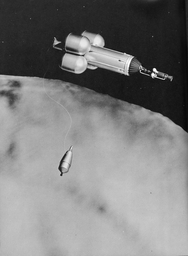

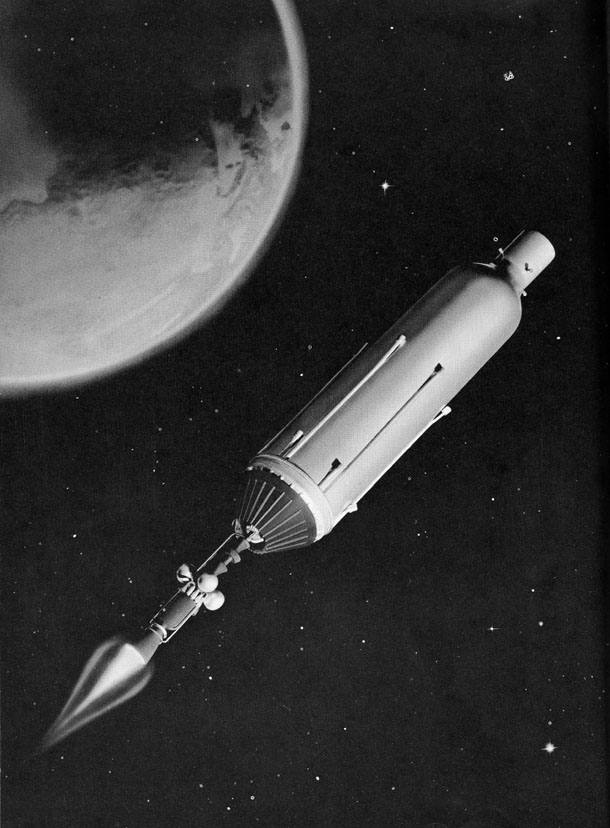
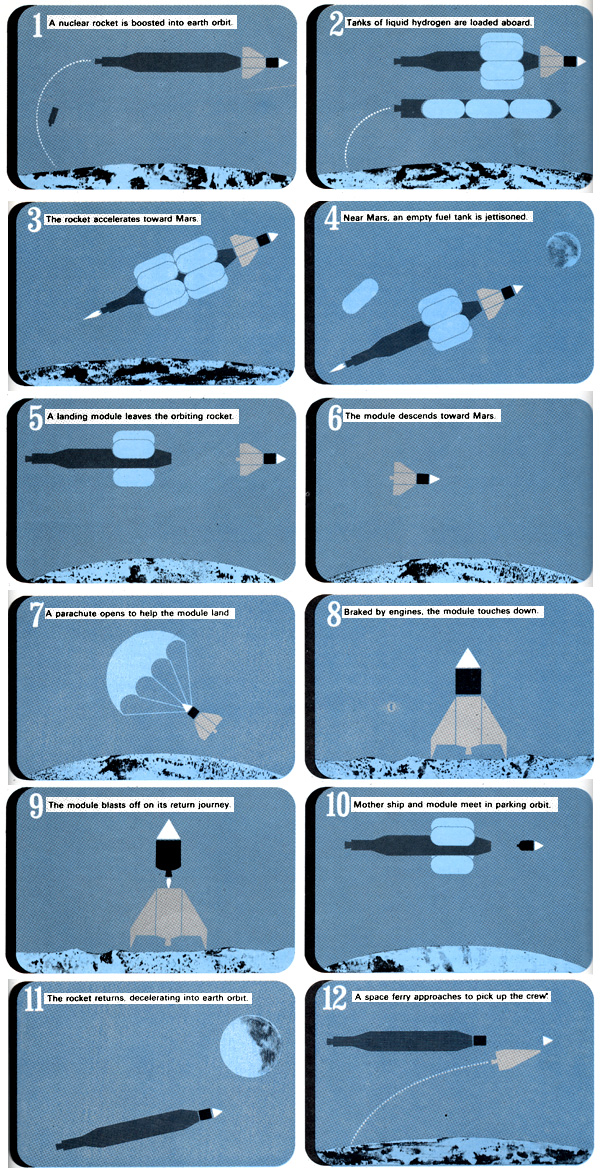
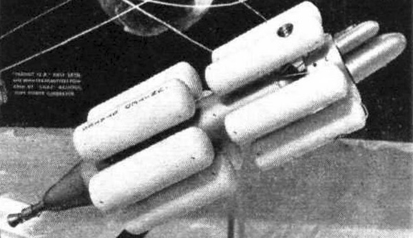
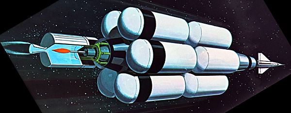

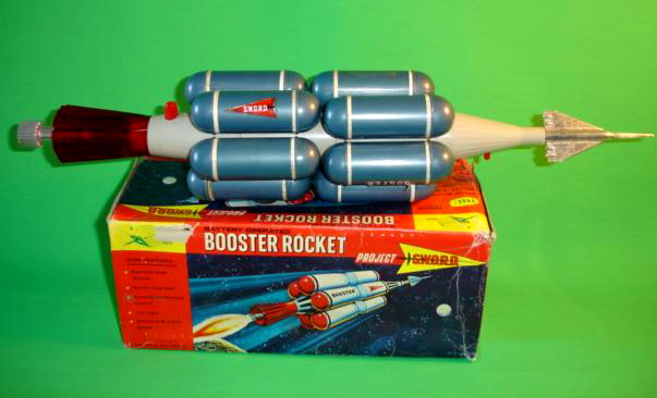
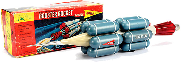
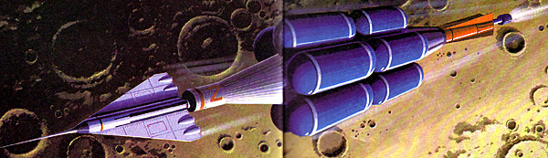
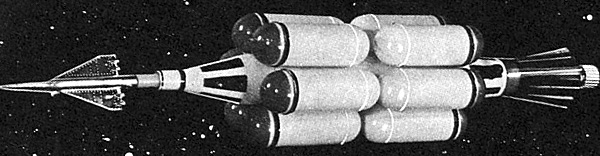
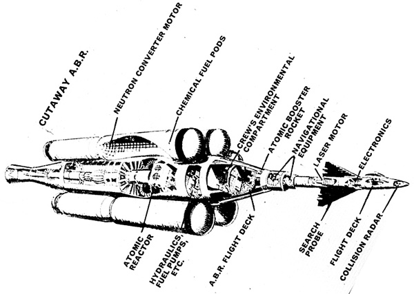
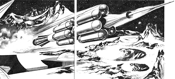
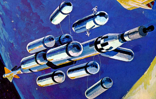
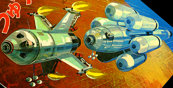
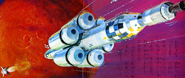

