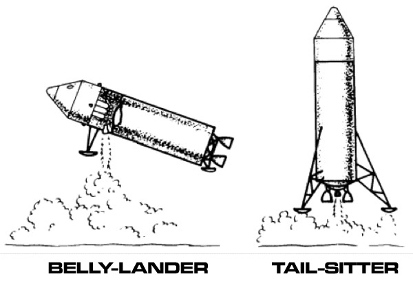
Embarking and debarking from an aircraft is relatively straightforward. You push a short set of steps up to the door and let the passengers go.
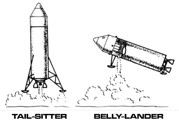
It is much more difficult with a tail-sitting rocket. Even more difficult if it occasionally lands on wilderness planets with no spaceports, launch towers, or other amenities. Compounding the problem is that if your rocket uses a fission reactor, you have to prevent the crew from receiving nasty doses of radiation while entering or leaving the ship.
If your rocket only takes off and lands from spaceports, this necessitates that the launch pads be equipped with launch towers that have elevators. The elevators can carry the crew and cargo to the loading hatches. You'd better include a way to move the tower away from the rocket before launch, especially if this is a nuclear rocket. The exhaust plume will violently terminate the tower's warranty. The rocket will be limited to landing at spaceports equipped with towers tall enough to reach the loading hatches.
Artwork by Ron Turner
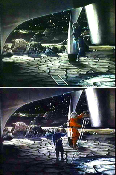
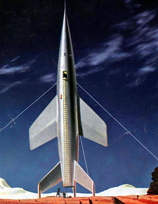
Things get more difficult if you are landing on a wilderness planet. The obvious solution is a species of ladder set into the side of the rocket. The one in the movie Destination Moon had individual rungs that could retract when you needed the hull to be aerodynamically smooth. That must be a maintenance nightmare.
However, you are now limiting your landing party to only able-bodied crew people. The ladder on the Destination Moon ship "Luna" is about 23 meters (75 feet). When was the last time you climbed a ladder that was eight stories tall? If you break an arm or leg, you are stranded. And there is no way to transport any large amount of cargo.
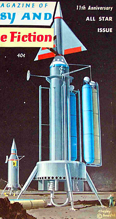
Galaxy Magazine, February 1951. Note guy wires stabilizing the spacecraft. Wires are attached to spacecraft's midsection instead of spacecraft's nose in order to minimize stresses.
In most rocket designs, the bottom edge of the hull is some distance above the ground due to the tail fins. This is generally to prevent the exhaust plume from splashing back onto the hull during landing. However, if your ladder is attached to the hull, the crew will have a problem with the gap.
In many SF images, they use an extenable attachment to bridge the gap, sometimes a rope ladder. In this scene from Destination Moon the crew carries down the lightweight extension. At the bottom of the hull they jump down to the ground, safe in influence of the weak Lunar gravity. Then they hook the extension onto the end of the hull.
Stairs are built into the landing jacks and tail fins, with a ladder on the hull.
Built-in elevator.
An overly long spiral ramp wrapping around the hull.
Tailsitter Cranes
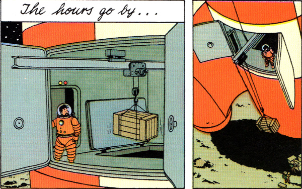
The traditional way to deal with the cargo and wounded crew member problem is with a crane.
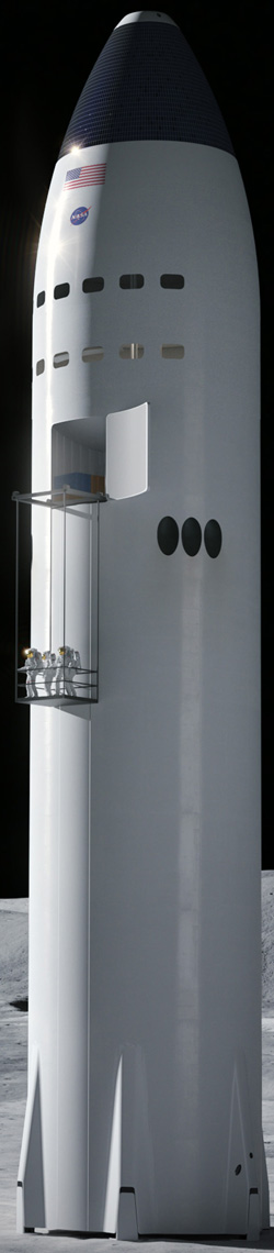
SpaceX lunar-optimized "Starship", with its long cargo crain
Generally you want to put bumps or bolts on the end of the girder, to prevent the little trolley from going to far and falling off.
From Tintin: Explorers on the Moon (1953) by Hergé (Georges Rémy)
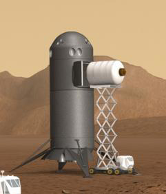
HSRV payload operations reusable scenario where mobility equipment is available for cargo offload
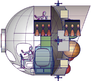
Tailsitters generally have the habitat module and cargo hold at the top, propellant tankage in the middle, engines near the bottom, and the landing gear at the very bottom. Leading to the tailsitter problem of the crew and cargo at the top of a rocket-shaped skyscraper.
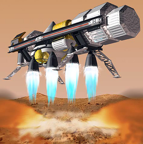
An unconventional solution (avoiding the problems of a belly lander) is to put the cargo and crew at the bottom, along with the landing gear.
This means having the engines at the top or the middle, firing at an angle (so the exhaust plume does not incinerate the cargo and crew). Or mounting the engine exhaust bells on three or four outriggers.
Angled engines is quite similar to a waterskiing spacescraft, along with the minor problem of cosine thrust loss. The other problem is now you need three or four smaller landing engines instead of just one. Besides the increase in cost, you have to carefully throttle each engine to the exact same thrust to keep it in balance. Otherwise the ship flips over and crashes.
instantly creating a dangerous crater right where you are landing.
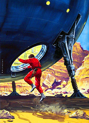
There is a half-arsed solution seen occasionally which is not very good. This is when you build the crew and cargo section as an annular ring around the engine exhaust nozzle. While it does get the crew and the cargo closer to the ground, it adds the problem of insulating the crew and cargo from the hot engine. If the engine in question is nuclear this solution is not worth it. About the only advantage is it allows you to use just one engine.
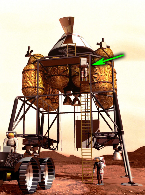
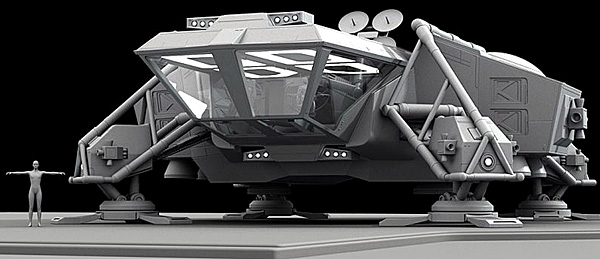
Four Engines on Outriggers I assume the corrugated red areas are cargo hatches with extendable cargo ramps artwork by David B. Mattingly
Angled Engines Crew module is at bottom, level with landing gear. Cargo module are above in hemi-pods. Four engines each in a swing-out pod. Fuel tanks on top
More details here Source
click for larger image
Angled Engines Refer to concept at upper right
More details here Source
click for larger image
Angled Engines Debarking port right on the bottom
from Space Journal #5, March-May 1959
artwork by Harry Lange
from Space Journal #5, March-May 1959 click for larger image
Angled Engines
See how having the cargo hold at the bottom allows unloading with a simple ramp
One of the draw-backs to a belly lander is that in the spacecraft in general, and in the habitat module in particular, the direction of "down" changes. Under thrust the direction of "down" is in the direction the exhaust is traveling, along the thrust axis. When landing on the ship's belly and while sitting on the ground impersonating an aircraft, "down" is at ninety degrees to the thrust axis.
Tail lander problem Don't slip on that ladder, astronauts! It's a long way down. And good luck getting any cargo back up to the ascent module.
Tail lander problem You better hope that elevator doesn't break. Image courtesy of Boeing
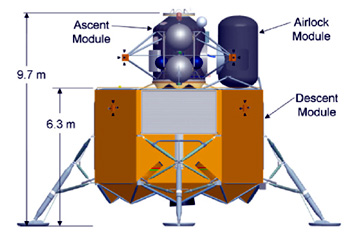
Tail lander problem United Launch Alliance's Altair lunar lander tries to minimize its length by using a multi-tank embedded design. But the blasted thing still forces the astronauts to climb down a 6.3 meter fall. It makes it difficult if you have to crawl down the equivalent of a three story building just to get on the surface. There must be a better way.
From AIAA 2009-6566
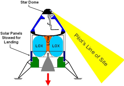
Tail lander problem Notice how the pilot cannot see what they are landing on, or even the landing legs. from AIAA 2006-7517-146
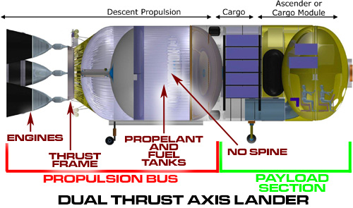
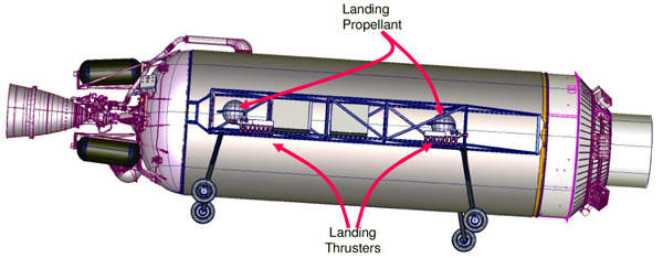
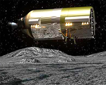
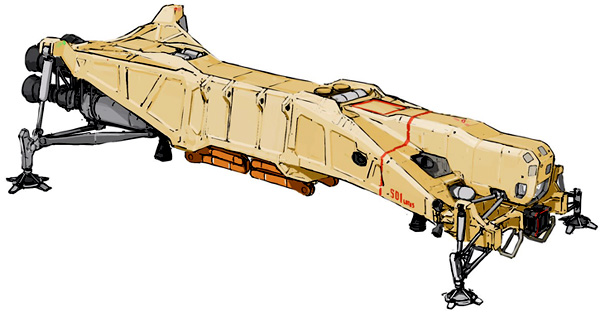
Belly lander solution United Launch Alliance's Dual Thrust Axis Lander (DTAL) travels through space using the main engine mounted on the long axis. For landing on the lunar surface, it uses the side landing thrusters to land on its belly. This puts the cargo much closer to the surface.
From AIAA 2009-6566
Belly lander solution Landing on its belly also gives the pilot a much clearer view of the landing site. Actually a tail lander does not allow the pilot a direct view of the landing site at all.
From AIAA 2009-6566
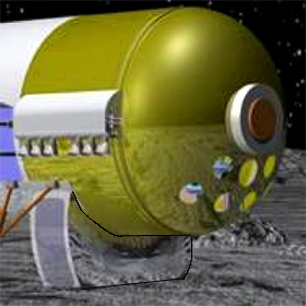
Belly lander solution The forward downward facing windows ("chin bubbles") give the pilot an unimpeded view of the landing site.
From AIAA 2009-6566
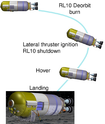
The RL10 main engine is used for the deorbit burn. At an altitude of about 1800 meters the DTAL rotates until the long axis is parallel to the ground. It then lands on its belly using the lateral thrusters.
From AIAA 2009-6566
Note how window points downward, acting as a chin bubble to assist landing
Note how belly-landing allows the access ladder to be relatively short. From NASA/JSC "LUNOX" proposal (1993)
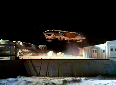
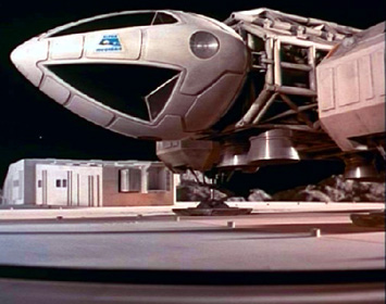
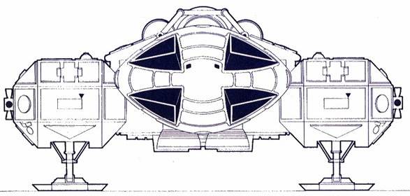
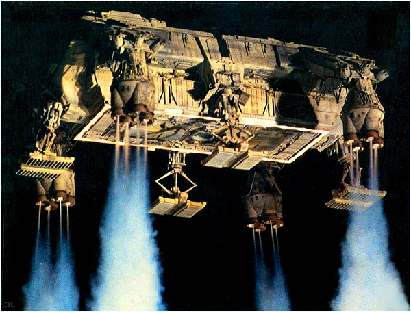
Note how there are downward pointing windows ("chin bubbles") as well as the standard upwards. Eagle Transporter from Space 1999
Artwork by Arthur Twosheds click for larger image
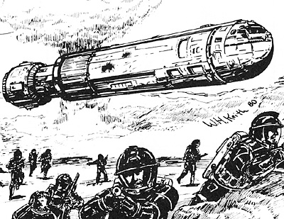
Traveller RPG Type R Subsidized Merchant starship ("Fat Trader"). Note huge cargo bay doors in rear. Artwork by William H. Keith, Jr. (1980)
Traveller RPG Type R Subsidized Merchant starship ("Fat Trader"). Artwork by Tom Peters (2012) Click for larger image
Traveller RPG Type R Subsidized Merchant starship ("Fat Trader"). Artwork by Rob Caswell (1988) Click for larger image
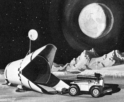
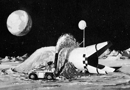
1963 Douglas concept for a simple lunar base. Spacecraft tilts for a horizontal landing. Artwork by Ron Simpson
Remote control nuclear powered drone tractor is deployed. Rear of spacecraft is a habitat module. Artwork by Ron Simpson
Drone tractor uses "snowblower" to cover spacecraft with lunar regolith. This provides protection against meteors, temperature extremes, and radiation. Artwork by Ron Simpson
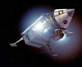
Cargo lander/Mars Ascent Vehicle Landing
artwork by NASA
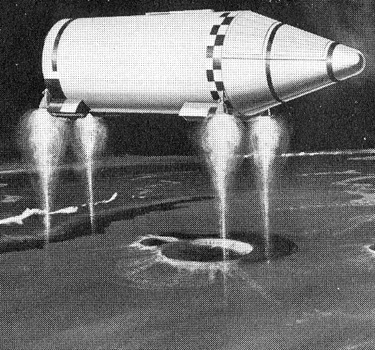
In this dangerous design, the rocket lands vertically, then the jacks contract and extend in order to bring the habitat module close to the ground...
... This reminds me of a giraffe trying to get a drink of water. It seems to me that this is risking several different kinds of catastrophic failure just to shorten the length of the rope ladder.
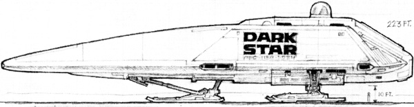
Artwork by Ron Cobb for Dark Star
Bottom Loader Embarking
This is a minor variation on Belly Lander. The payload can be lowered using hoists or cables directly, instead of requiring a crane.
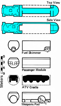
Traveller RPG Modular Cutter
Artwork by William H. Keith, Jr. (1980)
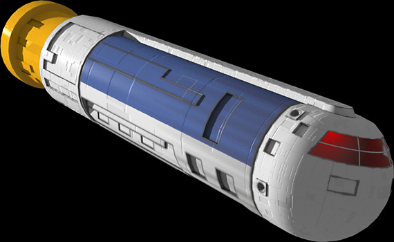
This is a small spacecraft whose midsection is a single standard cargo container. Eventually specialized midsections (with the same form factor) were created to alter the mission capabilities of the cutter just by swapping the midsections
Traveller spacecraft land using handwavium antigravity technology.
Note similar arrangement to Space 1999 Eagle Transporter: control cabin forwards, engine aft, dorsal spine, and interchangeable cargo modules.
From The Journal of the Traveller's Aid Society No. 5, 1980
Each module is 15 meters long, 6 meters wide, and has an internal volume of 420 cubic meters. The front and rear walls have a door that mates with the door on either the control or engine sections of the cutter. A module takes 2 minutes to attach/detach, 5 if in free fall.
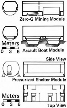
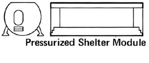
This module is intended as a habitat module on a planetary surface. It can be detached and left standing on its retractable legs. Airlock at each end, quarters for 8 crew members, small fusion power plant, air recycler, supplies for several months, galley, sanitary facilities.
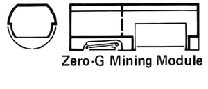
This module turns a modular cutter into an asteroid miner prospecting vehicle. Bay for ore samples, waldo arm for manipulating asteroids, living quarters for two.
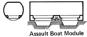
Transports 16 troopers in combat gear into battle. Hatches on lower surface have power spades. Upon landing the spades dig emergency entrenchments (in 15 seconds flat). The troopers leap into the entrenchments and the modular cutter departs. The cutter can remain for a few seconds to provide cover if more time is needed, say, to set up a command post, aid station, or mortar position. Hatches on the side allow egress if the landing site is not hot, and for boarding.
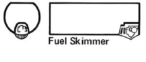
This module is for skimming fuel from a gas giant's atmosphere for wilderness refueling. The fuel is transported back to refuel the mothership. The fuel storage tank has a volume of 392 cubic meters. A linkage to the cutter's internal fuel tank allows refueling the cutter simultaneously with filling the module tank.
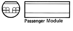
Accommodates 24 passengers in six rows of four seats abreast. Passengers enter from door leading to airlock in cutter's forward section. Military models cram in 60 passengers.
The module converts the cutter into a gunboat. A single turret with power plant, missile or laser weapon. Life support and room for support crew of four. Can also carry an extra missile magazine or droppable bombs. Module can be detached and left in orbit to provide fire support for ground troops.
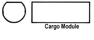
Holds 336 cubic meters of cargo. Module is loaded/unloaded by detaching module and sliding cargo in from the module ends. Variant lowers the amount of cargo and adds seats for 10 passengers.
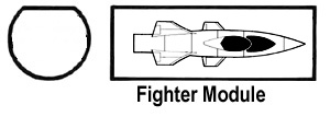
Holds four fighter spacecraft. All four can be launched simultaneously in less than a minute. Fighters reattach to the frame individualy, takes two minutes. The frame is open, rendering the cutter unstreamlined.
From Traveller Adventure 7 Broadsword (1982)
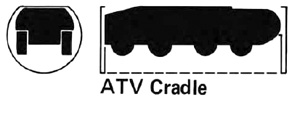
All terrain vehicle is held in cradle, while retractable hull preserves the cutter's streamlining. When landed, the hull opens, the vehicle is rotate 90° and lowered to the ground.
Cutter extends landing gear and approaches landing site under antigravity propulsion
artwork by Riftroamer
click for larger image
Touchdown
click for larger image
Module extend landing geer and detaches from cutter
click for larger image
Cutter lifts off straight up to avoid scraping module, only turning when clear of the module
click for larger image
Cutter retracts landing gear and departs
click for larger image
Streamlining shutters retract
click for larger image
Boom rotates All Terrain Vehicle (ATV) by 90°
click for larger image
Hoist lower ATV to the ground
click for larger image
Lifting hooks detach from ATV and it drives off
click for larger image
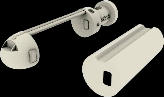
Artwork by Navanod Note how door on module rear (not shown but in same location as front) mates with door on cutter rear section.
Ehricke Slide Lander
This is Krafft Ehricke concept of how to drastically lower the delta V cost of delivering payloads to the Lunar surface. It seems crazy, but it just might be crazy enough to work.
As a slide-note, the Slide Lander concept makes a cameo appearance in Stephen Baxter's novel MOONSEED.
THE LUNAR SLIDE LANDER
If lunar transportation is based on oxygen/hydrogen, and if LULOX is used, the price for this advantage is the cost of importing H2, from Earth. It is therefore of vital importance to minimize this import. Fortunately,this can be done.
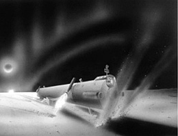
Figure 5. Nuclear-powered sweeper,designed for 1/6 g prepares and maintains an 80-km-long runway for the Lunar Slide Lander.
Conventional lunar descent and ascent are prime consumers of H2. But for ascent, there is a way to capture and reuse the H2 (see next section).And for descent, the amount of H2 required can be reduced to a fraction of that used by conventional systems.
A new concept, the Lunar Slide Lander (LSL), is proposed. It lands on a long, flat area and transfers its momentum to the lunar surface material, thus requiring very little propellant to land. This concept is not only decisively cost-saving, it avoids release of increasingexhaust gases as lunar traffic grows,preserving the Moon's valuable high vacuum for cost-effective ascent and for industrial uses.
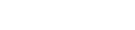
In the DS-3 discussion, it was suggested that Cynthia, the Central Lunar Processing Complex, be established in the far western part of Oceanus Procellarum because, among other reasons, a flat area for slide landing exists. Covered with dust and sand, it can be turned into a suitable landing stip with little preparation. I envision a landing strip sweeper (Fig. 5) that can easily cleanse the area of larger stones down to do a depth of 20-50 cm. My calculations show that the LSL braking surfaces go down only a few centimeters.
Touchdown at velocities of up to 5500 km/h, bringing the LSL to a halt along an 80-km-long landing strip through interaction with glassy-sandy material, introduces a new branch of spaceflight dynamics, for which I propose the term harenodynamics (from harenosus, Latin for sandy). Harenodynamics encompasses the dynamics of flow, boundary layer formation,and pressure, temperature,and gas (O2) release conditions in the boundary layer, at high speed flow of sand along harenodynamic brakes. The LSL's most critical component is its braking assembly, particularly the linings. It is desirable to manufacture the linings on the Moon from lunar materials. A harenomechanical and harenothermo-dynamic data base must be established to define target characteristics.
The lunar environment provides many advantages for slide landing. Vacuum permits high-speed LSL approach without temporary communication blackout due to ionized boundary layer formation. The absence of atmospheric effects, and superb sky and ground visibility (including optical signals at night) permit high predictability and automation of approach navigation. The LSL body as a whole is not subject to aerodynamic heating, which probably simplifies the design and results in lower structural mass. Possibilities for aborting the landing exist practically to touchdown.
The LSL descends from low CLO along an elliptic path. For elliptic descent from 10, 20, and 40 km, the supercircular velocity excess at perilune is about 5, 10, and 20 m/s. Therefore, a retromaneuver of only a few meters per second reduces the speed to subcircular and causes the LSL to approach the surface at a shallow downward path angle.
The approach phase is followed by a supporting vertical thrust phase, whose purpose is threefold: control of the touchdown point; fine adustment of the vertical velocity component for smooth touchdown; and initial support of most of the lander weight, to control deceleration and stability during the high-velocity phase.
The vertical thrust, which replaces the aerodynamic lift of a landing aircraft, is eventually terminated in the third and final phase. The slide time is about two minutes, of which supporting thrust is needed for at most 90 seconds. Average LSL weight during this period is about 0.8 of its full weight due to the centrifugal effect during the high-speed phase. The supporting thrust of the LSL at 16 tons full lunar weight requires, under these conditions, a propellant consumption equivalent to a velocity change of less than 120 m/s—much less than the almost 1700 m/s that must be eliminated at conventional landing. LSL propellant consumption is therefore reduced to less than 10% of that required for conventional landing, corresponding to a hydrogen expenditure per unit mass of payload of PH~0.01.
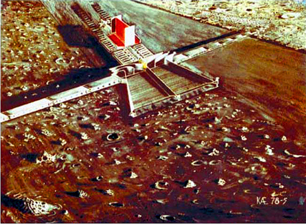
Figure 6. Touching down at 5500 km/h after descending from circumlunar orbit to the Moon, the O2/H2 Lunar Slide Lander tranfers its momentum to the surfoce materials and requires very little propellant to land. This concept will involve a small fraction of the H2 needed for landing by conventional methods, rendering lunar access an affordable matter of routine.
Figure 6 shows one of my LSL concepts. A very controlled touchdown begins with the aft edge which, together with the supporting thrust, stabilizes the vehicle for careful ground contact of the main drag vanes. These are spring supported, inclined, and in adjustable yaw position, in order to hurl the lunar material away from the vehicle. I have examined a multitude of other aspects for the slide landing process-navigational, harenodynamic, emergency options, etc. Suffice it to say that none appears to pose serious problems.
One of the big challenges in lunar exploration and development is the amount of delta-V needed get down to the surface and back again. On planets like Earth, and to a lesser extent Mars, spacecraft can dump momentum into the atmosphere for aerocapture, aerobraking, or aeroentry. The atmosphere does add some cost to the launch from those planets, but it provides a lot of benefit for landing. While the Moon’s gravity well isn’t that deep, it is enough that the rocket equation makes landing and return from the moon costly enough to be worth looking at alternatives. A purely rocket propulsion method for getting material to and from the Moon is a lot harder to close economically than when you can “cheat” and do a large chunk of that ascent/descent propellantlessly. While there are a lot of great ideas for propellantless launch from the Moon, there are a lot fewer options for propellantless soft-landing on the Moon. And very few of those are completely non-crazy.
One of the earliest such propellantless landing ideas I’ve seen was from space visionary Krafft Ehricke, where he suggested landing spacecraft horizontally using skids on a long, pre-cleared but unpaved landing strips. Momentum would be dumped via friction with the lunar regolith. Ehricke invented the field of “harenodynamics” to study the fluid-dynamics-like properties of regolith particles in that situation.
While this is an interesting idea, it also requires pre-landing pretty large construction equipment to clear the 10s of km long landing strip for landing. And it’s still pretty sporty from a controls standpoint.
So here’s the crazy thought I’ve been noodling for the past few weeks (spoiler alert: it doesn't work.). The fine portion of lunar regolith has a surprisingly high magnetic susceptibility–I’ve seen a demo where Dr Larry Taylor of University of Tennessee where he picked up actual lunar regolith samples inside a test tube using a magnet. What if you took a horizontal lander like ULA’s DTAL/Masten’s Xeus, and wrapped a really powerful magnet around it, and then flew really close to the lunar surface? As you fly over, you’d attract particles, and dump momentum into them. You’d have to cancel out the vertical forces (gravity minus centrifugal acceleration plus the vertical component of the momentum you impart as you pick up the lunar regolith), but there’s a decent chance that would drastically lower the propellant cost of a landing. Yes, this is crazy, since you’d be flying just above the lunar surface at ridiculous speeds (starting at the earth equivalence of Mach 5 horizontal velocity) for 1-2 minutes as you decelerate. What I’m curious about is if the ideas is just crazy, or if it’s crazy and also stupid.
Key questions I’d like to answer:
How much horizontal versus vertical force would such a system impart into the spacecraft–if too much of the magnetic force ends up pulling the spacecraft down into the regolith (compared with accelerating the regolith horizontally), then the idea won’t save you any propellant.
How close do you need to fly to the lunar surface on average for this to work. Are we talking 1m? 5m? 50cm?
How much horizontal deceleration force can you generate realistically? How it it effected by speed? I would think that at higher speeds you pass the particle too quickly to accelerate it all the way to your velocity, but as the speed gets lower you have more time to accelerate the particle.
How much “hovering” delta-V do you need to expend during the deceleration? If you can decelerate at 1G horizontally, the hovering delta-V just to cancel out lunar gravity would be less than 300m/s, much less than decelerating all the way from orbit.
Are there smooth enough stretches on the moon to realistically do this on an unprepared stretch of regolith? If you have to pop up to dodge a boulder (we’ve got good enough maps now that I’d think you’d be able to know in advance when you had to do such a maneuver), how much deceleration time do you lose? How much does that increase the “track length” you need to work with, if you assume a certain number of boulder hops per linear distance?
How powerful of a magnet do you need to make this work? Are we talking 0.5 Teslas? 1 Tesla? 10 Teslas? Does the magnetic hardware outweigh the propellant you’d save?
A few weeks ago, before I got sucked into proposal writing purgatory, I started making some physics models for the system. I found a good model for estimating the force on a magnetically susceptible regolith particle due to a magnetic field. I think my next analysis would be to model the trajectory of a particle as the lander passes by at various relative heights, speeds, and magnetic field strengths (I wonder if there’s some dimensionless number I can use to scale things?) Once I’ve done that I’ll have a better idea of how much momentum I can impart per particle, and how much additional vertical force I’ll need to null out. After that, the next step would be to take those drag numbers at various vehicle states, and use it to create a 1DOF landing simulation.
The cool thing is that if this works, it could theoretically work on first missions to certain sites, possibly allowing you to greatly decrease the cost of landing robotic cargo on the Moon in preparation for manned landings.
The idea is probably both crazy and stupid, but I figured it was worth sharing, in case there’s someone who likes the idea and has both the physics background to help me analyze this, more spare time than I do.
Addendum:
The lunar magneto-lithobraking concept I discussed in that blog post turns out not to work BTW. A particle that encounters a moving magnetic field gets accelerated and then decelerated by an equal amount, so no net momentum can be transferred in that way. There might still be a way to induce charge on dust particles in front of your vehicle and use a magnet to deflect them (sort of like how magnetoshell aerocapture charges and then deflects air particles to create drag), but it’s unclear if the magnitude would be enough to make it work.
As mentioned previously in Part 2 of this series, one of the key elements in establishing a lunar beachhead is developing ways to safely and affordably land payloads and people on the lunar surface. In Part 3, we discussed a way of hard-landing bulk raw materials on the surface, but in this post, I’ll focus on two related methods for horizontally soft-landing equipment and people on the Moon, while significantly reducing the amount of propellant required compared to traditional rocket-based soft-landing.
While the idea of horizontally landing on a planet with negligible atmosphere may sound odd at first, there is a method to my madness.
Horizontal Soft Lithobraking I’ve mentioned this concept in the introduction a previous blog post, but to recap for those who haven’t read the previous post, back around the time of the Apollo Program, Krafft Ehricke invented a concept for horizontally landing payloads and people on the lunar surface.
Ehricke’s concept involved having a lander with ski-like skids land on a very long (10s of km long) bulldozed regolith track. The lander skids would drag along the surface exchanging momentum with the lunar regolith. In this way the rocket delta-V associated with landing could be significantly diminished. Ehricke even invented a new field of engineering called “harenodynamics” to study the fluid-dynamics-like properties of regolith particles in that situation.
While probably doable, and while the concept would likely significantly increase the payload deliverable from Earth, it’s not without its share of drawbacks and challenges. Obviously, prepping such a landing strip would be no small feat. You would have to clear all boulders, level the ground as smoothly as possible, probably brake up and rake the regolith, and then you’d probably have to redo the strip after each landing, as the landers spray regolith in every direction. You’d probably also want a really, really accurate gravimetric map of the approach trajectory, and some good navigation aids, to enable the vehicle to hit the track, and hit it with the right velocity vector. This concept would likely result in a lot of wear and tear to both the track and the lander. Not to mention getting dust on pretty much everything, and being on the “that scares me, and I’m fearless” side of sketchy. But there’s also been a decent amount of research put into it, so it might be feasible.
That’s all I’ll say about his concept. For the rest of the post, I’d like to focus on a newer variation on the theme that I think has real potential.
MFA™ Hover-Brake Horizontal Landing
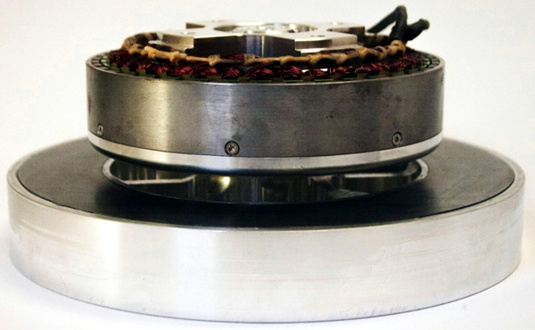
This second concept is a combination of a concept I heard from a friend at XCOR about a decade ago combined with some newer technology from a cool company in the Bay Area called Arx Pax. Arx Pax is probably most famous for their “Hendo Hoverboard”, which can levitate while carrying a full-weight human about an inch over a copper sheet, without using superconductors.
Their Magnetic Field Architecture (MFA™) technology works by using four “Starms” or “Hover Engines” which are rotating discs with magnets arranged on them in a way that projects most of the magnetic field down from the disc into the conductive medium you’re trying to hover over.
Arx Pax Hover Engine 3.0
As the Hover Engines rotors rotate, they induce a circular eddy current in the conductive medium, which creates a magnetic field that pushes back on the Hover Engines. Using two pairs of counter-rotating Hover Engines at the four corners of their hoverboard, they can push against the conductive medium with enough force to lift both the hoverboard and a human rider. They can also induce lateral forces by rotating the Hover Engines relative to the surface of the conductive medium. They think there may also be ways to modify their Hover Engines to induce push, shear, and pull forces on a conductive target. For those of you interested in learning more, Arx Pax just announced this last week that they’re now selling both a pair of the Hover Engine 3.0 modules shown above (capable of levitating 60kg at a height of 6mm over a 12.5mm thick sheet of 6101-T6 aluminum, with a system weight of <7kg each, as per this spec sheet) for $9,999 for the pair, as well as a MFA™ bundle kit with smaller hover engines and all the pieces you need to make and control your own hovering device for $1,589, both of which you can now order online here.
For this lunar landing application, you would need three elements: a long conductive track, multiple Hover Engines on the horizontal lander in order to levitate the lander over the track, and a magnet array on the bottom of the vehicle to decelerate the vehicle using eddy current braking with the long conductive track. The Hover Engines can help both keep the vehicle from touching the track, or from bouncing away from it, while also keeping it centered on the track, absorbing a lot of the shocks associated with a lunar landing, and providing additional deceleration force as the vehicle slows. As the Hover Engines approach the conductive track, the repulsive force should increase, and as the Hover Engines get too far above the track, the repulsive force should drop off, thus providing at least some natural feedback The amount of power needed to keep the Hover Engines rotating is probably modest enough to be powered by an APU like ULA is proposing for their Integrated Vehicle Fluids system. While there still are rather demanding requirements for hitting the landing track within the right cone of velocity vectors, the non-contact nature of this landing makes it somewhat less scary. And depending on the design of the eddy current braking magnets, the braking drag may be able to be applied gradually after the vehicle has established a clean hover on the track, if so desired.
One important question is still how much up-front infrastructure this may require. You’ll still need the bulldozer to remove boulders, and level the road. But you also no need a conductive layer of some thickness. The thickness is going to be driven by the float height, gravity, number and size of Hover Engines, and the conductivity of the conductive track. For earth hovering, they used a copper track of decent thickness. If we needed that thick of a track, that could add up relatively quickly, even if we go with lightweight aluminum instead of copper, to get the thickness down to much more reasonable levels.
Residual Resistance Ratio
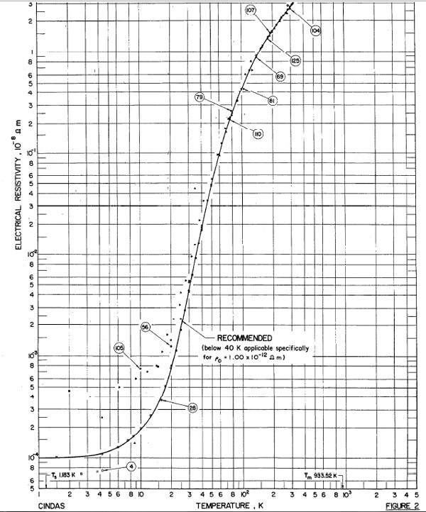
Most people are familiar with superconductors, but did you know that if you chill high purity metal conductors to cryogenic temperatures, that their resistivity also drops off dramatically? In most cases not all the way to zero, but enough to make a real difference. You need a very pure alloy (typically 99.99% or more of the base metal), fully annealed, with minimal impurities. But if you can get the metal in that condition, the conductivity can go up by 50-100x or more compared to their room temperature values. For instance, the figure below (from page 1135 of this paper) shows the conductivity vs temperature curve for high-purity aluminum. As you can see, the resistivity at room temperature is ~2.7×10^-8 Ohm*meters, but at LN2 temperatures it’s 10x lower, and LH2 temps it is ~3400x lower.
High Purity Aluminum Resistivity vs. Temperature
If you could chill pure Aluminum cold enough to reach ~125x the room temperature conductivity of 6101-T6 sheet (ie resistivity = .025 Ohm*m), you would need ~100µm of aluminum to conduct electricity as well as the 12.5mm thick sheet of aluminum at room temperature used for the Hover Engine 3.0 modules. From the chart that’s somewhere around 45-50K. 100µm is a lot more workable than 12.5mm. The 100µm thick layer could be thermally deposited onto a microwave fused regolith track to provide a strong mechanical backing, while keeping the initially imported aluminum mass quite low.
Running Some Initial Numbers
If you say had a 7.5m wide track with 100µm thick aluminum, the aluminum would mass approximately 2.03mT/km of track. So if you could hard-land a 70mT sample of such high-purity aluminum , and could recover approximately 2/3 of the aluminum, that would let you lay about 23km of conductive track from a single hard-landing flight. If you were using that 23km track to decelerate something from lunar orbital velocity (~1800m/s), and assumed that you were landing on ~80% of the track length, you could get the landing Gs down to ~9Gs (over approximately 20s). That’s only a little bit more intense than a Gemini launch on a Titan II missile and a bit gentler than a ballistic reentry in a Soyuz capsule, but probably within what a healthy human could handle safely. With two hard landings worth of aluminum under the above assumptions, you’d be able to get the G rate down to a totally survivable 4.5G deceleration (with a 46km long track).
But how much would all the Hover Engines mass to do this? Not as much as you’d think. So, if you assume that you’ve chilled the aluminum enough that 100µm of pure aluminum can conduct as much as 12.5mm of 6101-T6 aluminum can at room temperature (40-50K as mentioned above), so it behaves similarly to the nominal track thickness, that means that for landing a 20mT payload attached to a 6mT ACES/Xeus/HoverEngine lander, you’d need ~64 of the Hover Engine 3.0 modules (say 8 pods of 8 Hover Engines each), which without further weight optimization would mass around ~450kg. You could probably cut that down substantially with clever design, but that’s already in a similar order of magnitude to the mass of the landing kit for a rocket-powered Xeus lander.
As an aside, can you see why I was so interested in having a way to land large amounts of bulk raw materials on the lunar surface? Even though there’s plenty of aluminum in the regolith, and you could eventually setup facilities that could produce many tonnes of aluminum per year, being able to land that early-on dramatically lowers the cost of landing those facilities in the first place.
How to Chill
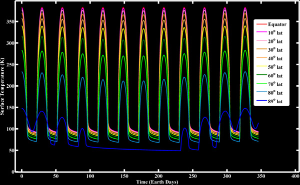
Getting back to the topic, can we really get aluminum cold enough to enable that level of conductivity? I’m honestly not sure. It may be possible to have the bulldozer that makes the path intentionally sink the track into the ground with berms around it in a way to keep the aluminum in shadow as much of the time as possible. If you combine that with some sort of “cryogenic selective thermal coating” that could help keep the temperature of the track passively cool for most of the day. Will it be enough to get the track down to the desired ~40-50K? I’m not sure. According to this chart from a site with data from the LRO Diviner mission, polar sites get down to around ~50K at night, so I don’t think it’s entirely crazy at least for polar locations. At more equatorial positions, even with a properly dug trench, you’ll likely need a thicker aluminum track to make things work.
Lunar Surface Temperatures over Time at Various Latitudes (from LRO Diviner Instrument)
One additional knob to turn is that apparently if you have a two layer track, with a highly conductive non-ferromagnetic upper layer, and a lower ferromagnetic layer, that the ferromagnetic sheet modifies the induced magnetic field in a way that actually increases the force pushing back on the Hover Engine. So theoretically, if you did a three layer design (first the microwave sintered regolith underneath, then a layer of melted NiFe material magnetically extracted from the lunar dust, and finally a layer of thermally deposited aluminum), you might be able to get a bit more bang for the imported aluminum buck.
Multi-Use Track
One other nice thing about a track like this is that it can provide two other uses other than just propellantless landing of people and payloads. First, the track is actually a pretty impressive conductor. A 100µm thick, 7.5m wide conductor has about the cross sectional area of a 1.25in (30mm) diameter rod. That’s a lot of conductor. And if chilled to 125x the room temperature conductivity of aluminum, you’re talking about a conductor equivalent to a 14in (350mm) diameter bar of aluminum at room temperature. A conductor that big could likely conduct megawatts of power over non-trivial distances. This means that you could have solar farms and installations located along the track, which all use the track as the high-power backbone to connect themselves to the main beachhead facility. If you had a polar facility with four tracks spaced 90 degrees from each other (say earthward, anti-earthward, and along and against the moon’s orbital velocity vector), you could locate solar farms along each track in a way that half of them are always in sunlight, so you wouldn’t need a lot of power storage capacity.
Second, the tracks also would serve as ideal highways/railroads for moving stuff between the main facility and other facilities down the line. Without air, and without rolling friction, these tracks could basically function as maglev railways linking installations up and down the track. The same Hover Engine kits used for landing could form the backbone of a hover vehicle that could rapidly move very heavy payloads up and down the track at very little energy cost.
And so long as you locate a track along a “great circle” route (ie a surface track that is in a plane that intersects with the center of the Moon), the tracks could be used for all three applications (landing, transportation, and power). While the first one or two could be built using Earth resources to accelerate their availability, once you have access to lunar aluminum, you can start putting tracks like this down wherever they are convenient, and as long and wide and thick as is convenient. I even have an idea for how you could use tracks like this for propellantless launching of payloads, but that’s a post for another day.
Conclusions
It’s probably more complicated than this. These ideas are very conceptual, and could use a significant amount of further baking. In fact, if I get a chance to flesh this out further, I’ll probably do follow on posts as Part 4.1, 4.2, etc. when I get the time. But they at least suggest that there may be ways to eventually cut the cost of delivering payloads to the Moon in-half, by getting rid of most of the propulsive landing delta-V. And for setting up heavy infrastructure on the Moon, the sooner you can get that big of a landing-cost savings, the more your overall system cost goes down.
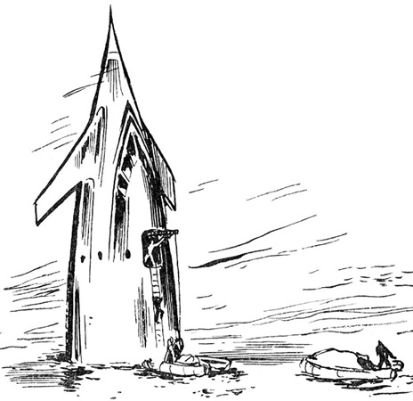
And if your ship is one of those specialized for water landing, embarking/debarking/load-unload cargo is a nightmare. A tail-lander floating at sea is going to have a large percentage of the body submerged underwater. It will not be able to get anywhere close to a shore-based wharf, not with its outrageous draft (draught). It will have to unload onto a free-floating wharf or a cargo naval vessel far away from the shore.
In this case it would make more sense to use some kind of belly-landing sea-worthy shuttle. That way you'll have a ship which has a small enough draft so it can float up to a wharf, quay, jetty, dock, or even a reserved berth; without ripping out the shuttle's belly on the jagged rocks on the harbor sea floor. The main ship can be a functional tail-sitter up in orbit.
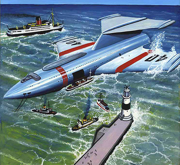
artwork by Bradshaw
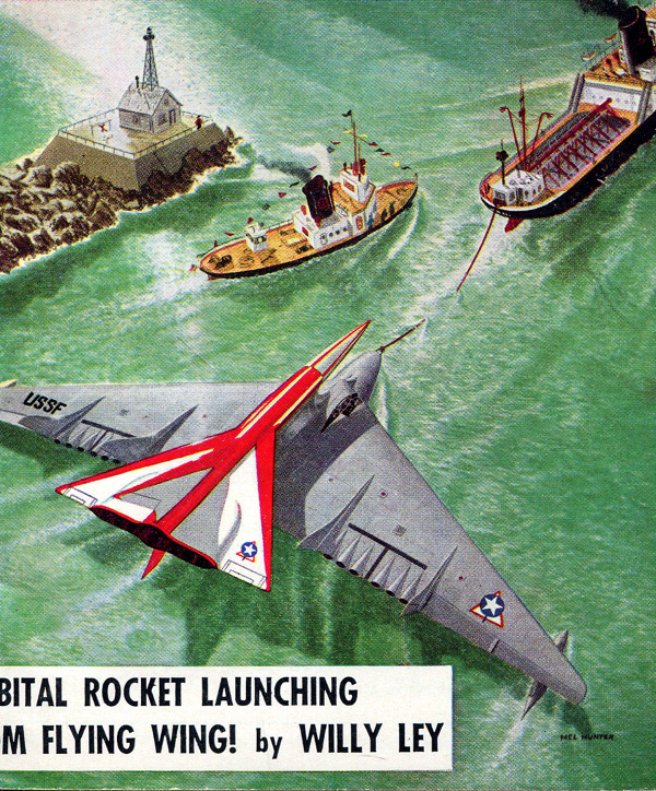
artwork by Mel Hunter
Time for the Stars
The "monkey island" is the platform atop the ship the helicopter is landing on. It is covering the top windows of the navigating bridge. The oblong hole near the waterline is the cargo port, lowering the whale boats.
Of course things get exciting if there are hostile aliens living in the water. But all you have to do is turn on the torch drive for about thirty seconds to kill everything in a kilometer radius.
(ed note: The good starship Lewis & Clark (L-C or "Elsie") is a torchship, and lands in the water. Otherwise its mass-converter powered torch drive would have the ship landing in a huge crater of freshly-created boiling lava. Also, since Elsie is exploring newly discovered planets, there will be no existing landing facilities. Landing in the smooth water is far safer than landing on uneven ground.
The mass coverter can use water or any other non-corrosive fluid as fuel. A "monkey island" is a nautical term referring to an open platform at the top most accessible height or an open deck directly above the navigating bridge, pilothouse, or chart house. In the Lewis & Clark, the navigating bridge is right at the top of the starship.)
When they left, I was on top of the Elsie glumly watching them get into the boats. There was a "monkey island" deck temporarily rigged up there, outside the airlock; it was a good place to watch the boats being loaded at the cargo ports lower down. Engineering had completed inspection and overhaul and had about finished filling the boost-mass tanks; the Elsie was low in the water and the cargo ports were not more than ten feet above waterline(naturally the more full the propellant tanks, the lower the ship sits in the water). It made loading convenient; at the time we put the first party ashore the tanks were empty and the boats had to be lowered nearly a hundred feet and passengers had to go down rope ladders—not easy for people afraid of heights, as so many are. But it was a cinch that day.
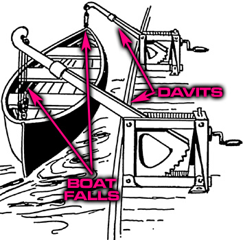
The airlock was only large enough for people; anything bigger had to go through the cargo ports. It was possible to rig the cargo ports as airlocks and we had done so on Inferno around Beta Hydri, but when the air was okay we just used them as doors. They were at the cargo deck, underneath the mess deck and over the auxiliary machinery spaces; our three boats and the two helicopters were carried just inside on that deck. The boats could be swung out on gooseneck davits from where they nested but the helicopters had to be hooked onto boat falls (a tackle used to hoist or lower a ship's boat from or to the davits), swung out, then a second set of falls hooked to them from the monkey island above, by which a helicopter could be scooted up the Elsie's curved side and onto the temporary top deck, where her jet rotors would be attached.
Mr. Regato cursed the arrangement every time we used it, "Mechanical buffoonery!" was his name for it. "I've never seen a ship's architect who wasn't happy as soon as he had a pretty picture. He never stops to think that some poor fool is going to have to use his pretty picture."
As may be, the arrangement did let the helis be unloaded with a minimum of special machinery to get out of order—which, I understand, was a prime purpose in refitting the ships for the Project. But that day the helicopters were outside and ready, one of them at camp and the other tied down near me on the monkey island. All we had to do was to load the boats.
The boats were whale boats molded of glass and teflon and made nonsinkable by plastic foam in all dead spaces. They were so tough that, while you might be able to bash one in, you could not puncture it with anything short of a drill or a torch, yet they were so light that four men could lift one that was empty. It did them no harm to drive them up onto a rocky beach, then they could be unloaded and easily dragged higher. They were driven by alcohol jets, just as the helis were, but they had oars and sails as well. We never used the oars although all the men had gone through a dry drill under my Uncle Steve's watchful eye.
They went through narrow whitewashed corridors, then into the bright Florida sunshine. A narrow gangway led to the forward end of an enormous winged landing ship that floated at the end of a long pier crowded with colonists and cursing guards.
The petty officer spoke briefly to the Marine sentries at the officers' gangway, then carefully saluted the officer at the head of the boarding gangway.
The ship circled the harbor, then glided in on its stubby wings to settle into the chop outside the breakwater. The waves were two meters high and more, and the ship rolled badly. One of the new recruits was sick. His seatmate handed him a plastic bag.
Soon the shuttle moved into the inner harbor, where there were no waves, and everyone felt better. A lone tugboat came alongside and eased the spacecraft toward a concrete pier. There was no other traffic in the harbor except for a few small fishing boats.
The landing boat fell away from the orbiting warship. When it had drifted to a safe distance, retros fired, and after it had entered the thin reaches of the planet's upper atmosphere, scoops opened in the bows. The thin air was drawn in and compressed until the stagnation temperature in the ramjet chamber was high enough for ignition.
The engines lit with a roar of flame. Wings swung out to provide lift at hypersonic speeds, and the spaceplane turned to streak over empty ocean toward the continental land mass two thousand kilometers away.
The ship circled over craggy mountains twelve kilometers high, then dropped low over thickly forested plains. It slowed until it was no longer a danger to the thin strip of inhabited lands along the ocean shores. The planet's great ocean was joined to a smaller sea by a nearly landlocked channel no more than five kilometers across at its widest point, and nearly all of the colonists lived near the junction of the waters.
Hadley's capital city nestled on a long peninsula at the mouth of that channel, and the two natural harbors, one in the sea, the other in the ocean, gave the city the fitting name of Refuge. The name suggested a tranquility the city no longer possessed.
The ship extended its wings to their fullest reach and floated low over the calm water of the channel harbor. It touched and settled in. Tugboats raced across clear blue water. Sweating seamen threw lines and towed the landing craft to the dock where they secured it.
Lysander peered down through orange clouds. The ground was invisible, but cloud wisps streaked past, and stress diamonds formed near the wingtips of the landing ship. It was eerily quiet in the passenger cabin. Lysander turned from the viewport to his companion, a young man about twenty and much like himself. "Mach 25, I'd guess," Lysander said, then caught himself. "Fast. Faster than sound, Harv. A lot faster."
The landing ship banked sharply, then banked again. Strange accelerations lifted the more than two hundred passengers from their seats, then slammed them down again. The ship turned, banked, turned again in the opposite direction. Lysander remembered the dry voice of his ground school instructor explaining that delta wing ships lose energy in turns. Lysander had certainly learned that on the flight simulator and later in his practice re-entry landings. He glanced outside. The landing boat had a lot of energy to lose before it could settle on one of Tanith's protected bays.
Barton's binoculars gave him an excellent view of the stubby-winged craft as it settled in on the choppy water. It skirted the crimson waves where the nessies were fighting and sped across to the dock area at too high a speed, turning just in time. It had come full speed close enough to the pier to make Barton wince.
"Hotshot," he muttered. Most landing boat pilots were.
"Worried about nessies. I would be too," Honistu said.
The Talin class was the smallest of the CD's assault/pickup boats. It looked fairly large, but most of its bulk was tankage and engines behind a small cabin and cargo area. The Talin class was designed to carry a marine assault section, two metric tonnes, to orbit, or bring twice that mass from orbit to ground. Its mission was to land troops in unexpected places. And that we've done, Ace Barton thought.
Crewmen appeared at the aft hatches and caught lines thrown from the docks. The landing boat was winched in until it lay against the pier. The broad landing hatch opened.
A crew snaked fuel lines out. A minute after they were connected up, they glistened with condensing frost. The fuel and oxygen lines crossed the road to the pier, and the ranch hands had put up a steel crossover to allow trucks to drive over them without pinching them off. Now a mixed crew of ranch hands and Barton Bulldogs was unloading crates from the trucks and carrying them aboard the landing craft.
From THE PRINCE by Jerry Pournelle and S. M. Stirling (2002)
Nuclear Complications
Things become vastly more complicated if the engine is radioactive. Due to mass considerations, the reactor is usually unshielded, except for a "shadow shield" which only protects the habitat module. When the crew start down the hull ladder, they will soon be exposed to the glow of deadly radiation. It might be worth the mass penalty to add some side shielding to protect the ladder. Or parts of the shadow shield could be rearranged.
When we stepped out of the little car it went back where it came from. In front of me was a ladder disappearing into the steel ceiling above. Dak nudged me. "Up you go." There was a scuttle hole at the top and on it a sign: RADIATION HAZARD-Optimax 13 Seconds. The figures had been chalked in. I stopped. I have no special interest in offspring but I am no fool. Dak grinned and said, "Got your lead britches on? Open it, go through at once and straight up the ladder into the ship. If you don't stop to scratch, you'll make it with at least three seconds to spare."
I believe I made it with five seconds to spare. I was out in the sunlight for about ten feet, then I was inside a long tube in the ship. I used about every third rung.
From DOUBLE STAR by Robert Heinlein, 1956
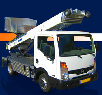
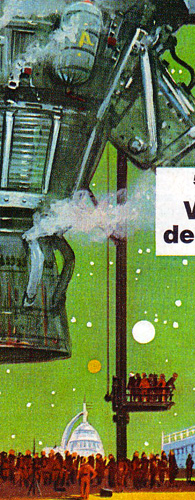
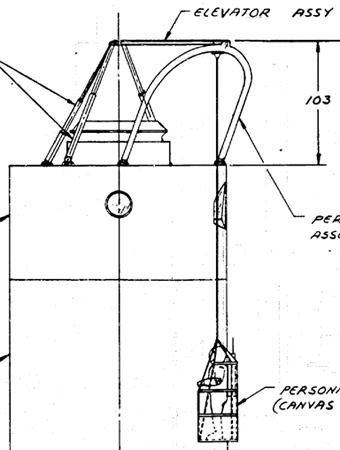
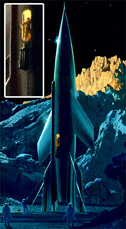
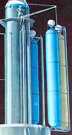
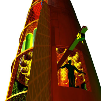
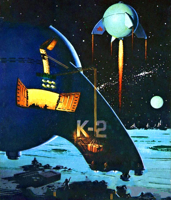
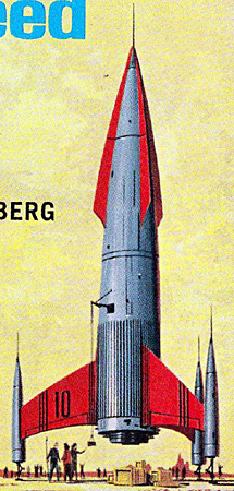
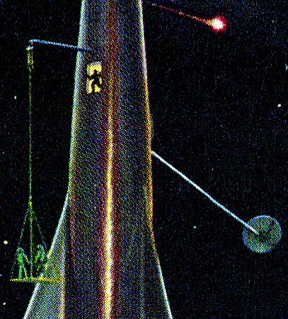
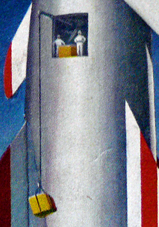
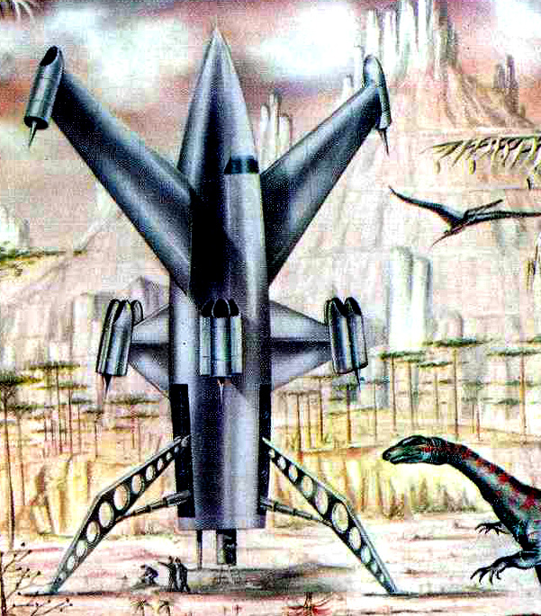
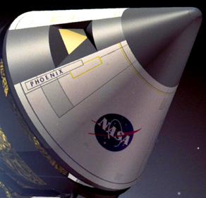
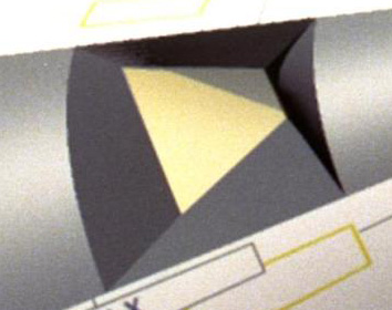
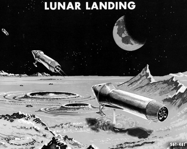
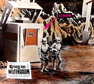
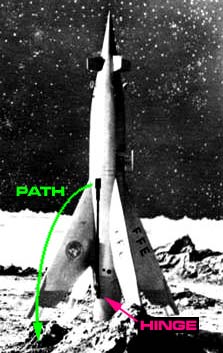
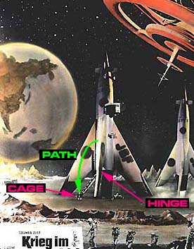
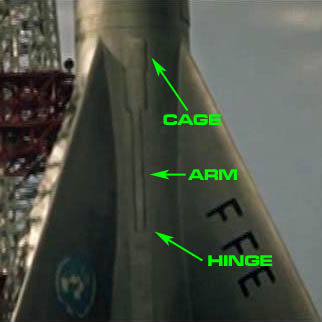
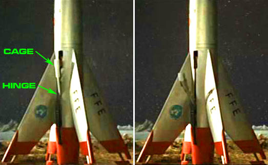
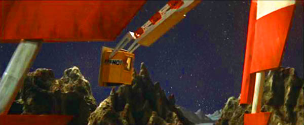
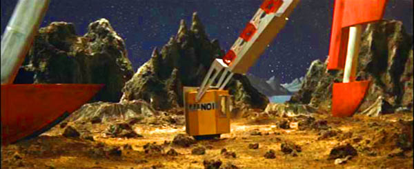
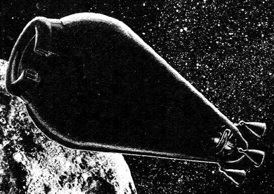
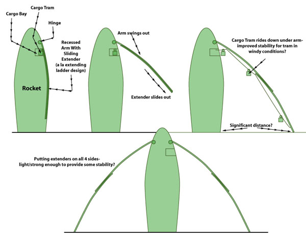
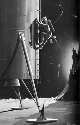
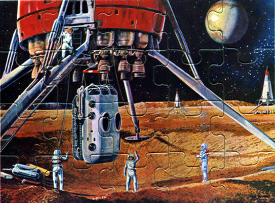
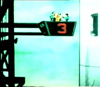
An interesting solution was in the old "B" movie Battle in Outer Space. Consider, if a girder is thirty meters long when it is vertical, it is still thirty meters long if horizontal. Say that thirty meters is a safe distance from the atomic drive in the ship's tail. Attach a thirty meter girder by a hinge on the atomic drive, and put an elevator cage on the other end. When the girder is vertical, the landing party enters the cage, a safe thirty meters from the drive. The girder then pivots on the hinge until the cage is on the ground. All this time the landing party is still at a safe distance. They then exit the cage onto the planet's surface. If the ship is streamlined, the girder and cage will be recessed into the hull, with the outer part of the girder covered by the ship's skin (you can see the recess hole in the middle picture above).
There was a similar arrangement in The Jupiter Theft by Donald Moffitt.
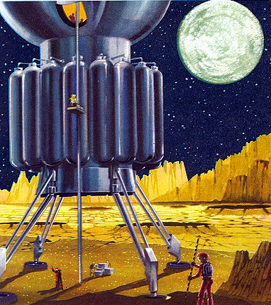
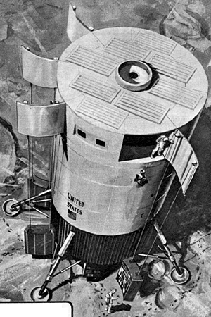
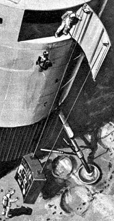
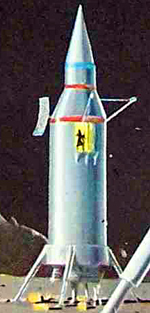
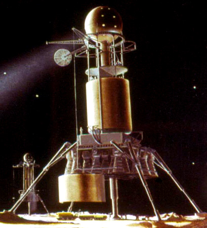
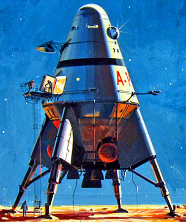
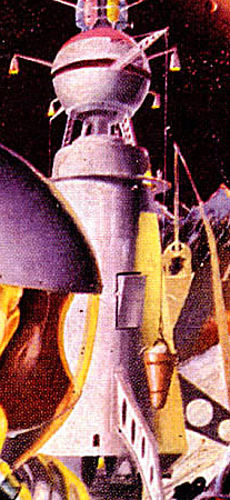
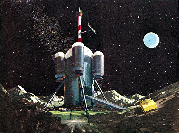
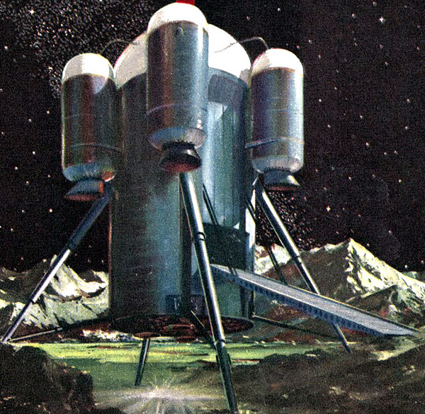
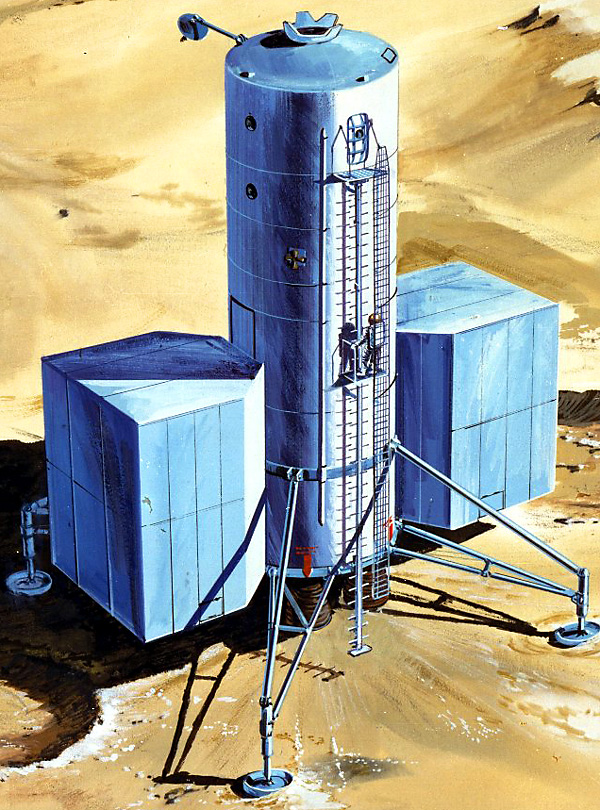
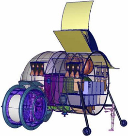
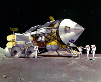
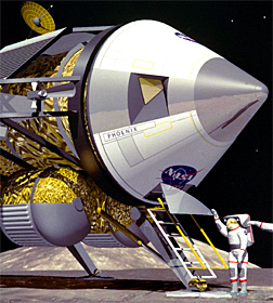
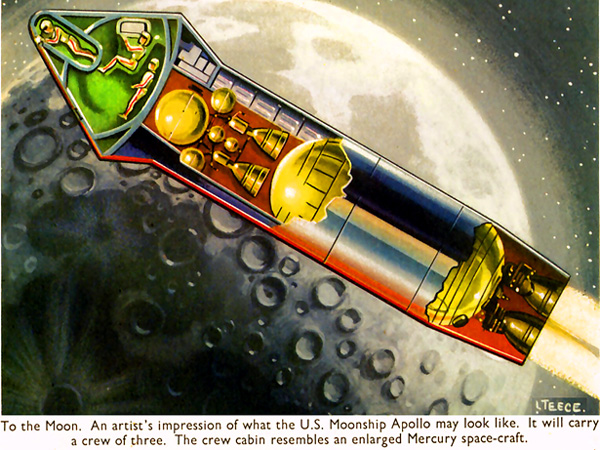
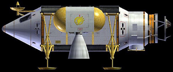
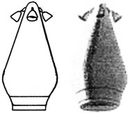
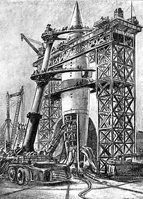
To the right is an 1961 design proposal by Douglas Missile and Space Systems for an atomic powered lunar lander, the radioactive propulsion unit is in the nose of the ship. This allows astronauts to exit the landed ship without going near the atomic pile.
detail
Other Ideas
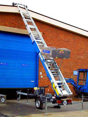
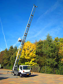
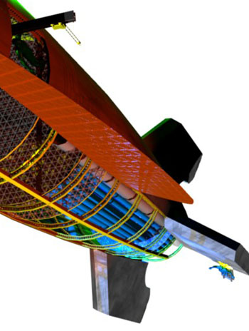
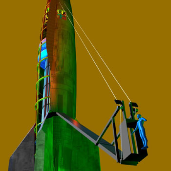
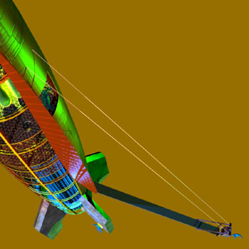
JanJaap
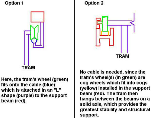
The engineer known as JanJaap has made a design trying to make the Battle in Outer Space solution actually work. The movie solution would require most of the interior of the ship to be filled with elevator machinery. JanJaap's solution uses cables instead, to create a collapsible tram way.

 The Trouble with Tailsitters