|
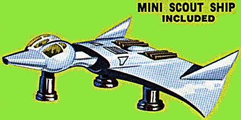
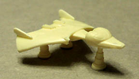
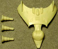
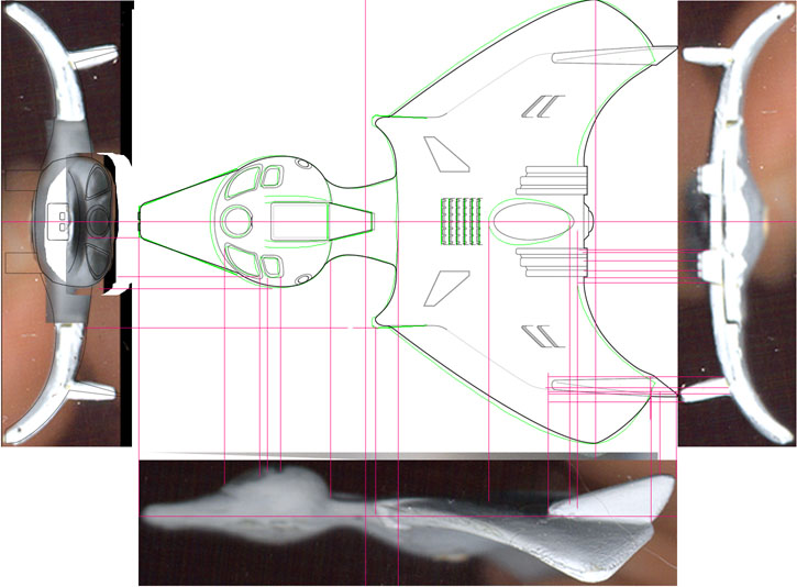
Now it's time for the hard part. The Scoutship. Just look at all those smooth hard-to-model curves and rounded surfaces. Mr. Merrill graciously gave me some half-finished prototype blueprints of the scoutship. I merged these with some terminally blurry images of the model that I made by holding it edgewise on my flatbed scanner. The results are crude, but better than nothing. The plastic model is at 1:500 scale. Measuring the scoutship from nose to the middle of the wing's trailing edge with my handy-dandy calipers and multiplying by 500 with my slide rule gives me a scoutship size of approximately 17 meters. I decided that each Blender scale unit would be one meter, and re-sized the image of the blueprints accordingly. This will be important when I finish the scout and wish to import it into a scene with the Leif Ericson. I have to be able to re-scale the scout to fit the Leif's scale. |
|
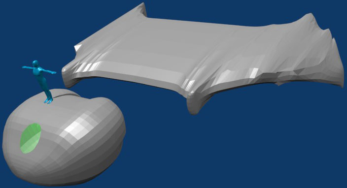
I thought that doing curved surfaces would be difficult, and I was correct. Part of the problem is that a blueprint of a curve provides few reference points, except for the outline. The other problem is that I'm trying to do this with a rectilinear mesh, instead of using Blender's NURBS surfaces like I should. I may eventually use NURBS, but frankly they intimidate me. To help scale things I added a little blue manikin which is 1.8 meters tall in reference to the scout. This will help when I get around to creating the cockpit interior. The man figure was created by Riku Nurminen. |
|
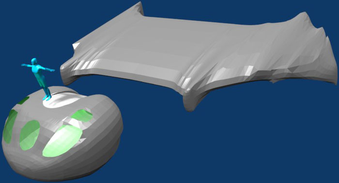
I had separate views for top view, side view, and front view. Each had the appropriate blueprint loaded into the background. I made a Blender "uv sphere" primitive at the head's location set so the north pole was at the nose and the south at the head's aft. The lines of latitude were at ninety degrees to the long axis of the ship. The starboard half was deleted, a "linked-duplicate" of the port half was created, made a mirror image, and moved into place. This means that I only have to work on half the head, and Blender will automatically maintain bilateral symmetry by mirroring each change on the other side. It was easy to "scale" the upper/lower halves and the fore/aft halves so that the ovoid matched the outline of the head on the blueprint. I thought that was a little too easy, and I was correct. Using the top view, I added vertices matching the outline of blueprint's image of the center circular window. Glancing at the front view, I was dismayed to see that the vertices did not match the front blueprint. The basic problem is that the top and side outlines do not provide enough reference points to mold the mesh. Blender probably has better tools to fix such problems, but I'm still learning the tool set. What I did was: [1] I set the 3D cursor to be in the center of a ring of latitude which crossed the circular window. This will be the origin of the scaling operation. [2] I selected all the vertices in that line of latitude. [3] Watching the front view, I re-scaled the ring of latitude until the window vertices aligned with the blueprint. [4] I turned my attention to the next ring of latitude crossing the circular window and went to step [1]. Why did this work? When I initially set the circular window vertices in the top view, I was setting their X and Y coords, and using the mesh surface for the Z coord. The front view revealed that the Z coords were incorrect. By re-scaling the rings of latitude, I was altering the Z coords without altering the X and Y (by much, at any rate). I then cut the two grooves in the aft of the head. |
|
|
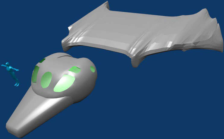
Here's the scout with all the windows cut, and the rings of latitude re-sized. That was a lot of work. After re-sizing the rings, the surface of the head was no longer smooth. Looking at the wireframe one could see that the lines of longitude were crooked. I spent a lot of time manually moving vertices so both the lines of longitude and latitude were straight, which smoothed the surface of the head. You can still see a discontinuity at the ring of latitude just forwards of the windows, but I figured they would be covered by the pointy nose so were not worth spending time on. The wings are going to be tedious, I can tell. I started with a square flattened to a thick slab. It was mirror duplicated like the head in order to make the other wing. Using the top view, I added vertices and moved them to carve the slab into an outline of the wing. Then using the side view, I moved the vertices to match the top edge of the wing in side profile. I then turned on Blender's "sub-surface modeling" feature, resulting the messy wing you see. Refining the outline will smooth out the wing. I will also have to expand the outline so the subsurface image aligns with the blueprint. |
|
I turned on the "smoothing" feature for the head, for all the polygons except the ones defining the rear grooves. A square primitive was molded into a truncated pyramid for the nose, also smoothed. The big problem was removing the parts of the nose that extended inside the head. Ordinarily one does not have to do this, except that the rear of the nose is visible through the windows. When I do the control panels and pilots in their acceleration couches I do not want the rear of the nose getting in the way. |